Article

Novel Enhanced Modular Multilevel Converter for High-Voltage Direct Current Transmission Systems

1
Institute of Energy, PEDEC Group, Electronic and Electrical Engineering Department, University of Strathclyde, Glasgow G1 1XW, UK
2
Renewable Energy Research Group and Department of Electrical and Computer Engineering, Faculty of Engineering, King Abdulaziz University, Jeddah 21589, Saudi Arabia
*
Author to whom correspondence should be addressed.
Energies 2020, 13(9), 2257; https://doi.org/10.3390/en13092257
Submission received: 24 January 2020 / Revised: 25 March 2020 / Accepted: 30 March 2020 / Published: 4 May 2020
(This article belongs to the Special Issue Multilevel Power Converters Control and Modulation Techniques)

Abstract

:
This paper proposes an enhanced modular multilevel converter as an alternative to the conventional half-bridge modular multilevel converter that employs a reduced number of medium-voltage cells, with the aim of improving waveforms quality in its AC and DC sides. Each enhanced modular multilevel converter arm consists of high-voltage and low-voltage chain-links. The enhanced modular multilevel converter uses the high-voltage chain-links based on medium-voltage half-bridge cells to synthesize the fundamental voltage using nearest level modulation. Although the low-voltage chain-links filter out the voltage harmonics from the voltage generated by the high-voltage chain-links, which are rough and stepped approximations of the fundamental voltage, the enhanced modular multilevel converter uses the nested multilevel concept to dramatically increase the number of voltage levels per phase compared to half-bridge modular multilevel converter. The aforementioned improvements are achieved at the cost of a small increase in semiconductor losses. Detailed simulations conducted in EMPT-RV and experimental results confirm the validity of the proposed converter.

1. Introduction

Half- and full-bridge modular multilevel converters (HB-MMC and FB-MMC, respectively) provide solutions for connection and reinforcement of weak AC networks [1,2,3]. They become the dominant technologies for DC transmission systems, and their reactive power capabilities play vital roles in stabilization of weak AC networks that operate near stability limits [4,5]. Some additional features they offer are as follows. High efficiency and power quality at both ac and dc sides and internal fault management, which is critical for fault-tolerant operation during failure of few cells [6,7].
The two established approaches for the commercial realization of the HB-MMC are as follows.
  • The first approach uses a large number of cells per arm, in which each cell is rated for 1.6–2.8 kV [8]. This approach avoids series connection of semiconductor switches and permits generation of high-quality ac and dc side waveforms with near-zero harmonics and dc ripples, and simplifies the bypass of faulty cells. However, the main downsides are excessive complexity of the power circuit and control and protection.
  • The second approach employs a reduced number of medium-voltage (MV) cells per arm, in which each cell is typically rated for n (16–20) kV [9]. This approach requires series connection of press-pack insulated gate bipolar transistors (IGBTs), with safe short circuit mode. It addresses the shortcomings of the first approach, but the use of MV cells in the arms introduces significant errors in the synthesis of the common and differential mode voltages, which appear as dc voltage ripples and ac side harmonics. Therefore, small ac and dc side filters are needed in order to match the performance of the first approach.
Besides the HB-MMC and FB-MMC, several multilevel converters have been developed in recent years [10,11,12,13,14,15,16,17,18,19,20,21]. For example, multilevel converters that employ unipolar cells such as three-level flying capacitors tend to inherent the attributes and limitations of the HB-MMC such as high efficiency and inability to remain controllable during dc faults [12,13,22]. Apart from HB cells, none of the alternative unipolar cells received industrial acceptance in the form of practical adoption in physical projects due to the high complexity of the internal fault management when limited number of cells fail. On other hand, asymmetrical cells permit controlled operation of multilevel converters for a wide range of positive input dc link voltages, from rated to zero, including control of dc fault current and dc fault blocking. These type of cells can be configured in a manner to allow for delivery of bespoke features and control range for any given efficiency [12,13,14,15,16,17,18,19,20]. The symmetrical bipolar cells, in which the FB cell belongs, permit the maximum operation and control range, including potential bipolar dc link voltage operation in generic dc grids alongside the line commutating converters (LCCs) and dc fault control and blocking. Multilevel converters with symmetrical bipolar cells tend to have the worst efficiency, with those implemented using asymmetrical cells tend to provide the middle ground.
This paper puts forward the EMMC to address the power quality shortcomings of the HB-MMC that employs reduced number of MV cells. The EMMC exploits a novel concept of nested multilevel operation, in which the HB chain-links generate a rough stepped approximation of sinusoid fundamental voltage with major voltage steps of 16 kV to 20 kV. Although the FB chain-links facilitate multilevel operation with minor voltage steps of (1–2.5) kV between the major the voltage steps of the HB chain-links, the FB chain-link in each arm of the EMMC operates as an active power filter and generates anti-phase voltage harmonics that nullify the inherent harmonics in the component of the arm voltage that the HB chain-link synthesizes. The introduction of few FB cells into the EMMC arms has helped to reduce the errors in the synthesis of the common and differential mode voltages. In this way, the EMMC matches the performance of the HB-MMC that employs large number cells, which is achieved by small modifications to the power circuit of the HB-MMC that uses reduced number of MV cells.
The rest of the paper is organized as follows. Section 2 describes the fundamentals of the EMMC. Section 3 presents simulation and experimental validation of the EMMC. The scalability of the EMMC and comparisons with HB-MMCs are investigated in Section 4. Section 5 presents the main findings and conclusions drawn of this paper. In this paper, for example, Figure 1, Table 1, and Equation (1) are cited in the text as Figure 1, Table 1, and Equation (1), respectively.

2. Enhanced Modular Multilevel Converter

This section describes the fundamentals that underpin the power circuit, modulation, and control of the EMMC as detailed in subsequent subsections.

2.1. Power Circuit

Figure 1 shows one phase leg of the EMMC, which consists of upper and lower arms. Each EMMC arm comprises a HB and FB chain-link. The HB chain-link of the EMMC is designed to block the full dc link voltage, it consists of MV-HB cells, and is responsible for the synthesis of the fundamental voltage. In contrast, a FB chain-link of the EMMC is rated with total blocking voltage equal to half of the blocking voltage of a single MV-HB cell. The suffixes h b and f b stand for HB and FB cells/chain-links, respectively, and the HB and FB cell voltages are described as
V c e l l h b = V d c N h b
where V c e l l h b is the HB cell capacitor voltage, N h b is the number of MV-HB cells in the HB chain-link, and V d c is the pole-to-pole dc voltage.
V c e l l f b = V c e l l h b 2 N f b
where V c e l l f b is the FB cell capacitor voltage and N f b is the number of FB cells in the FB chain-link of each arm of the EMMC. Therefore, the total number of cells N per arm of the EMMC is defined as in Equation (3).
N = N h b + N f b
Recall that the conventional HB-MMC with N h b HB cells per arm generates N h b + 1 voltage levels per arm, whereas the proposed EMMC generates 2 N h b · N f b + 1 voltage levels per arm. This multiplication effect enables the EMMC to generate more voltage levels per arm or phase compared to the conventional HB-MMC with an equivalent number of cells, as shown in Equations (4) and (5).
N H B M M C o = N + 1
where N H B M M C o represents the number voltage levels per arm of the conventional HB-MMC.
N E M M C o = 2 N h b · N f b + 1
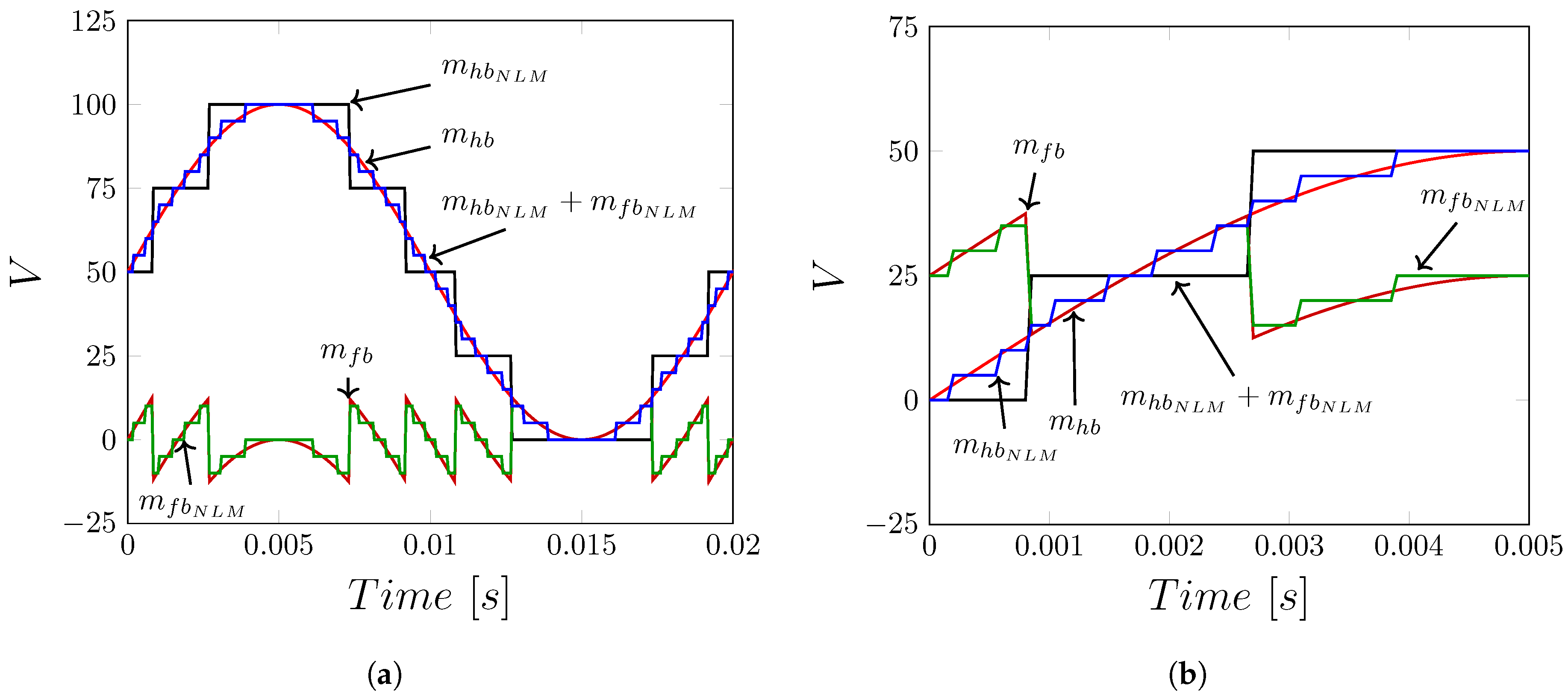
Figure 2a shows the target arm voltage superimposed on the rough stepped approximation of the arm voltage as will be synthesized by the HB chain-link, and Figure 2b displays the target and stepped approximation of the FB chain link voltages. Observe that the HB chain-links of the EMMC synthesize a rough stepped approximation of the sinusoidal fundamental voltage V c h a i n h b with a major voltage step equal to ( V c e l l h b = V d c N h b ) , whereas the FB chain-links synthesize bipolar voltages V c h a i n f b with positive and negative peaks of ± V d c 2 N h b = 1 2 V c e l l h b ) and minor a voltage step of ( 1 16 V d c = ± V d c 2 N f b · N h b = V c e l l h b 2 N f b ) . The total arm voltage V a r m of the EMMC is the algebraic sum of the voltages V c h a i n h b and V c h a i n f b to be synthesized by the HB and FB chain-links, respectively. The voltage step of the total arm voltage V a r m is equal to the FB cell capacitor voltage ( V D C 2 N h b N f b = V c e l l h b 2 N f b ). The positive and negative peaks of V c h a i n f b in each arm are limited to ± 1 2 V c e l l h b , which suggests that the minimum blocking voltage of the FB chain-link is 1 2 V c e l l h b . For example, the EMMC with four MV-HB cells and three LV FB cells is capable of generating 25 voltage levels in each arm. Figure 2c presents a detailed view that illustrates the stepped approximation of the total arm EMMC voltage superimposed on the voltage being synthesized by HB chain-link, and target arm voltage. It can be seen that the total arm voltage tracks the target arm voltage closely, with fine voltage steps equal to the FB cell capacitor voltage or simply minor voltage step.
The HB cell capacitance can be calculated from the equivalent capacitance of the HB chain-link C c h a i n l i n k h b as
C c e l l h b = C c h a i n l i n k h b · N h b
where C c e l l h b is the cell capacitance for the HB chain-link. Similarly, the cell capacitance C c e l l f b of the FB cell is expressed in terms of HB cell capacitance C c e l l h b and the number of FB cells N f b as
C c e l l f b = C c e l l h b · N f b 2
After rearrangement of Equation (7), it can be deduced that the total capacitance of the FB chain-link is equal to half the capacitance of one HB cell. The capacitance of a single HB cell of the EMMC is sized based on stored energy criteria, which necessitates the ratio of total energy stored per EMMC to the rated apparent power must be in the range of 30 to 40 kJ/MW [9]. Using this approach, Equations (6) and (7) will guarantee that the FB and HB capacitor voltage ripples remain but do not exceed ±10% as in conventional HB-MMC.
Note that the inclusion of FB cells into the arms the EMMC is not intended for facilitation of dc fault blocking nor reduced dc voltage operation as in mixed cells MMC (MC-MMC).

2.2. Operating Principle, Modulation, and Control

The EMMC exploits MV-HB cells that constitute the half-bridge chain-links to synthesize the fundamental voltage with major voltage steps of V D C N h b , as shown in Figure 3a, while the FB cells that form the full-bridge chain-links are used as series active power filters to remove the excessive harmonic contents from the rough voltage generated by the HB chain-links, and to facilitate orderly, stepped, and multilevel waveforms with minor voltage steps V D C 2 N h b · N f b , between successive major steps of the HB chain-links. In this way, the FB chain-link of each EMMC arm facilitates a smooth transition between the major successive voltage levels, through intermediate voltage levels, separated by minor voltage steps. As the HB chain-link synthesizes the fundamental component of the arm voltage, the continuous modulating signal m h b is used as an input the nearest level modulation stage in order to estimate the number of HB cells to be inserted and bypassed from each arm, see Figure 3a. As the FB chain-link in each EMMC arm requires the injection of voltage harmonics for the reason stated above, its modulating signal is extracted as an error between the target fundamental voltage (which is continuous signal) and its staircase approximation as shown in Figure 3b. Thus, the modulating signals for the HB and FB chain-links are
m h b = M · c o s ( ω t + δ )
m h b N L M = r o u n d ( m h b · N h b ) / N h b
m f b = m h b N L M m h b
m f b N L M = r o u n d ( m f b · N f b ) / N f b
where M represents modulation index. Equations (8)–(11) show the synthesis of the modulating signals of the FB and HB cells, respectively. The total dc voltages across the FB and HB chain-links are evenly distributed across their respective capacitors with the aid of conventional sorting or tolerance band-based capacitor voltage balancing methods [23,24].

2.3. Theoretical Bases of Modulation and Control of the EMMC

For simplicity, the EMMC phase leg “a” will be considered in this section, in which the upper and lower arms ar signified by 1 and 2, respectively. The FB and HB cell capacitor currents can be described in terms of arm current and their respective cell switching functions. Therefore, the FB and HB chain-links switching functions are
s h b i = 1 N h b S c e l l h b , i
s f b k = 1 N f b S c e l l f b , k
i c e l l h b , i , k = S c e l l h b , i , k · i a r m k
i c e l l f b , j , k = S c e l l h b , j , k · i a r m k
The EMMC arm voltage v a r m k represents the algebraic sum of the HB and FB chain link voltages v c h a i n l i n k H B k and v c h a i n l i n k F B k as described in Equations (16)–(19):
v c e l l h b k ( t ) = 1 C c e l l h b · i c e l l h b k ( t ) d t
v c e l l f b k ( t ) = 1 C c e l l f b · i c e l l f b k ( t ) d t
v a r m j , k = y = 1 N h b s c e l l h b k · v c e l l h b k + y = 1 N f b s c e l l f b k · v c e l l f b k
or
v a r m k = V c h a i n l i n k H B k + V c h a i n l i n k F B k
The common-mode voltage that the EMMC phase leg a presents at the dc terminal is the sum of the upper and lower arm voltages ( v a r m 1 , v a r m 2 ):
V c m = v a r m 1 + v a r m 2 = V d c ± d V
where d V represents the dc voltage mismatch that would be handled by arm reactors, which could affect the synthesis of ac voltage and common-mode currents [25]. The two necessary conditions for balancing different capacitors of the EMMC are as follows; the net energy exchange between different chain-links and ac and dc sides must be zero and the net energy exchange between the FB and HB chain-links of each arm must be zero. The former condition is ensured through vertical horizontal capacitor voltage controllers; while the latter requires extra controllers to ensure the total arm voltage is split correctly between the FB and HB chain-links. The aforementioned conditions could be expressed mathematically as
E a r m k = 0 T v a r m , j , k · i a r m k ( t ) d t = 0
E c h a i n l i n k H B j , k = 0 T v c h a i n l i n k H B · i a r m j , k ( t ) d t = 0
E c h a i n l i n k F B j , k = 0 T v c h a i n l i n k F B · i a r m j , k ( t ) d t = 0
The dc component of the modulating signal of the FB chain-link of each EMMC phase keg, m f b , is adjusted to ensure zero energy exchange with the HB chain-link as stated earlier. The adjustment of the FB modulating signal m f b is achieved through dedicated voltage or energy based controller.

2.4. Assessments of Semiconductor Losses

As the EMMC adds few extra semiconductor switches to its arms, its total semiconductor loss is expected to be marginally different from that of the HB-MMC. In an EMMC with 640 kV dc link voltage, 40 HB cells, and five FB cells, the blocking voltages of the HB and FB chain-links are 640 kV and 8 kV, respectively. The EMMC HB and FB cells will block 16 kV and 1.6 kV, respectively, which indicates that the contribution of extra FB chain-links of the EMMC to overall losses is negligible. The semiconductor losses are calculated from the EMMC model that applies the NLM to both HB and FB chain-links, with switching frequencies of the HB cells that remain within 150 to 300 Hz. As FB cell has twice switches as the HB cell, the total conduction loss per FB chain-link of the EMMC is equal to that of one HB cell. Thus, the total EMMC conduction is expressed in term of that of the HB-MMC as show in Equation (24). The total switching loss of the FB chain-links is low because of their low cell/switching voltages (1.6 kV compared to 16 kV in HB cells). As the blocking voltage of the FB cell is relatively low, the Silicon Carbide Metal Oxide Semiconductor Field-Effect Transistor (SiC-MOSFET) can further lower the switching losses of the EMMC from the level offered by the existing Insulated Gate Bipolar Transistor (IGBT).
P E M M C c o n d = N h b + 1 N h b · P M M C c o n d
Equation (24) shows the relationship between the increase in total semiconductor losses and number of HB cells, ignoring switching and passive filter losses. Moreover, it shows the EMMC semiconductor loss decreases as the number of MV-HB cells increases. Table 1 summarizes a comparative semiconductor loss study conducted between the following.
  • Conventional IGBT-based HB-MMC with 40 HB cells per arm, with each cell is rated for 16 kV, which will be referred to as M M C 40 S i I G B T .
  • Conventional IGBT HB-MMC with 400 cells per arm, which will be referred to as M M C 400 S i I G B T .
  • EMMC with 40 Silicon IGBT-based HB cells and five IGBT FB cells per arm, referred to as E M M C 40 + 1 S i I G B T .
  • EMMC with 40 IGBT-based HB cells and five SiC-MOSFET FB cells per arm, referred to as E M M C 40 + 1 S i C M o s .
The computed semiconductor losses are obtained from the detailed power loss model in [26], which accounts for junction temperature, IGBT and diode threshold voltage drops, on-state resistance, turn-on and turn-off energy, and diode recovery energy. The observations drawn from Table 1 are as follows.
  • The EMMC exhibits slightly higher on-state loss compared to the conventional HB-MMC with 40 and 400 cell per arm when silicon IGBTs are employed.
  • Among the silicon-based IGBT converters, M M C 400 S i I G B T and M M C 40 S i I G B T have the lowest and highest switching loss, whereas the E M M C 40 + 1 S i I G B T shows level switching loss, which is lower than M M C 40 S i I G B T and M M C 400 S i I G B T . This is because of the dominant effect of switching voltage in the conventional HB-MMC with 400 cells.
  • The total semiconductor loss of the E M M C 40 + 1 S i I G B T is marginally lower than that of the M M C 40 S i I G B T , but higher than that of the M M C 400 S i I G B T .
  • Further reduction in semiconductor loss of the SiC-MOSFET EMMC, E M M C 40 + 1 S i C M o s , is possible.
Based on the basic design presented, the EMMC increases semiconductor count by 2.5%, which can be offset by other design considerations such as cell redundancy.

3. Experimental Validation

This section uses the experimental results obtained from a scaled-down prototype of single-phase EMMC with parameter listed in Table 2. Each arm of EMMC prototype contains four HB cells, each rated to block 75 V, and four FB cells, each rated to block 18.75 V. In experimental studies, the HB chain-link is controlled using NLM as originally envisioned, whereas the FB chain-link is controlled using high-frequency level shifted pulse width modulation (LS-PWM), with 2.5 kHz carrier frequency (one carrier per FB cell). Both chain-links adopt the sorting-based capacitor voltage balancing method. The HB cell capacitance is sized based on inertia of 40kJ/MVA. The EMMC arm inductance is sized to be equivalent to 0.2 pu.
The entire modulation and capacitor voltage balancing of the EMMC are implemented by two low cost 32-bit Arm® Cortex®-M3 PSoC microcontrollers ( M C U 1 and M C U 2 ) from Cypress Semiconductor. Externally generated 50 Hz sinusoidal modulating signals are fed to M C U 1 and M C U 2 . M C U 1 manages NLM and capacitor balancing of the upper and lower HB chain-links, whereas M C U 2 implements high-frequency LS-PWMs that employ carrier frequency of 2.5 kHz and capacitor voltage balancing of the upper and lower FB chain-links.
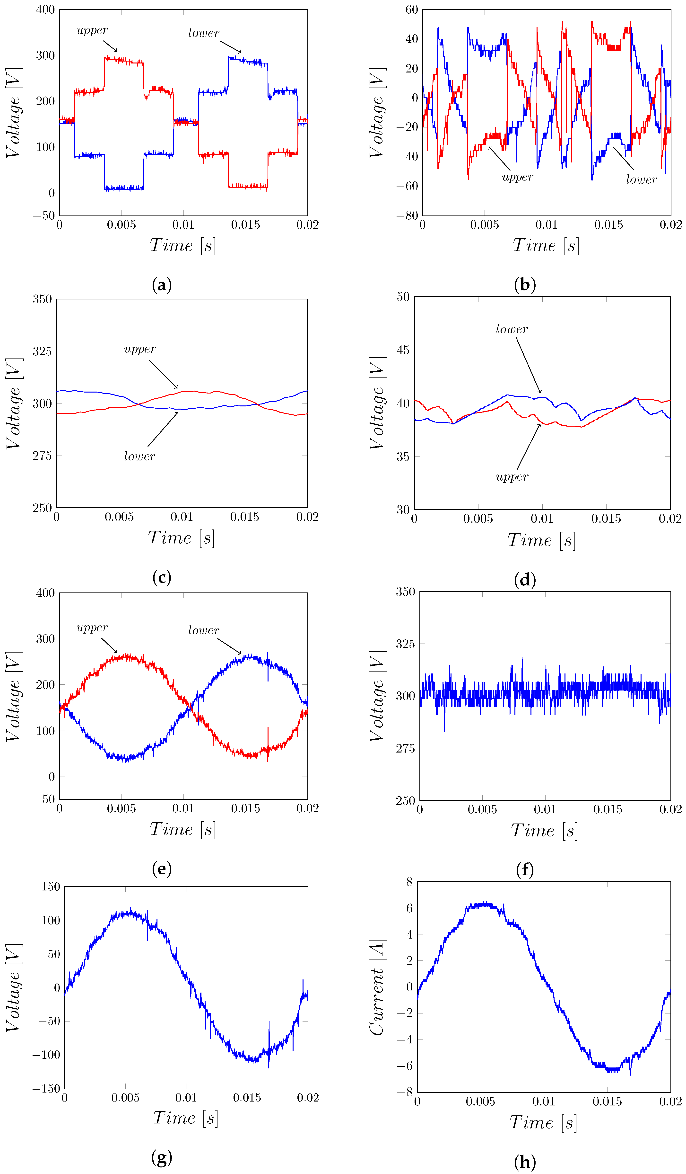
Figure 4 presents experimental waveforms as part of the validation of the EMMC when its ac side feeds a passive load of R L O A D = 17 Ω . The observations drawn from the experimental results in Figure 4 are as follows.
  • Figure 4a shows the upper and lower arm voltages of the HB chain-links, v c h a i n l i n k H B 1 and v c h a i n l i n k H B 2 . Observe that these HB Chain-link voltages are rough-stepped approximations of the fundamental voltage plus dc bias, with major voltage step of 75 V ( V d c N H B ) as described in Section 2.
  • The plots for the upper and lower arm voltages of the FB chain-links, v c h a i n l i n k F B 1 and v c h a i n l i n k F B 1 , are bipolar and vary between 37.5 V ( V d c 2 · N H B ) and -37.5 V ( V d c 2 · N H B ) through intermediate voltage levels with minor voltage step of 9.25 V ( V d c 2 · N H B · N F B )
  • Figure 4c,d presents the voltage sums of the upper and lower arms of the HB and FB cell capacitors of the EMMC. These waveforms indicate that the HB cell capacitor voltage sums are tightly regulated around the V d c = 300 V, while the FB cell capacitor voltage sums are regulated at approximately V d c 2 · N H B = 37.5 V.
  • Figure 4e displays the total arm voltages v a r m 1 = v c h a i n l i n k H B 1 + v c h a i n l i n k F B 1 and v a r m 2 = v c h a i n l i n k H B 2 + v c h a i n l i n k F B 2 . Observe that the total arm voltages v a r m 1 and v a r m 2 are better approximations that closely match the theoretical modulation functions of the EMMC arms. Notice that these fine waveforms are achieved with the EMMC that employs only four HB cells and four FB cells per arm.
  • Figure 4f shows that the common-mode voltage that the EMMC presents at the dc side matches the dc link voltage and contains noticeable high frequency due to few number of cells per arm of the experimental prototype.
  • Figure 4g,h present interesting results that show the EMMC with only four HB cells and four FB cells per arm generates better approximation of desired sinusoidal voltage and current than the conventional HB–HB.

4. Scalability and Performance Comparison

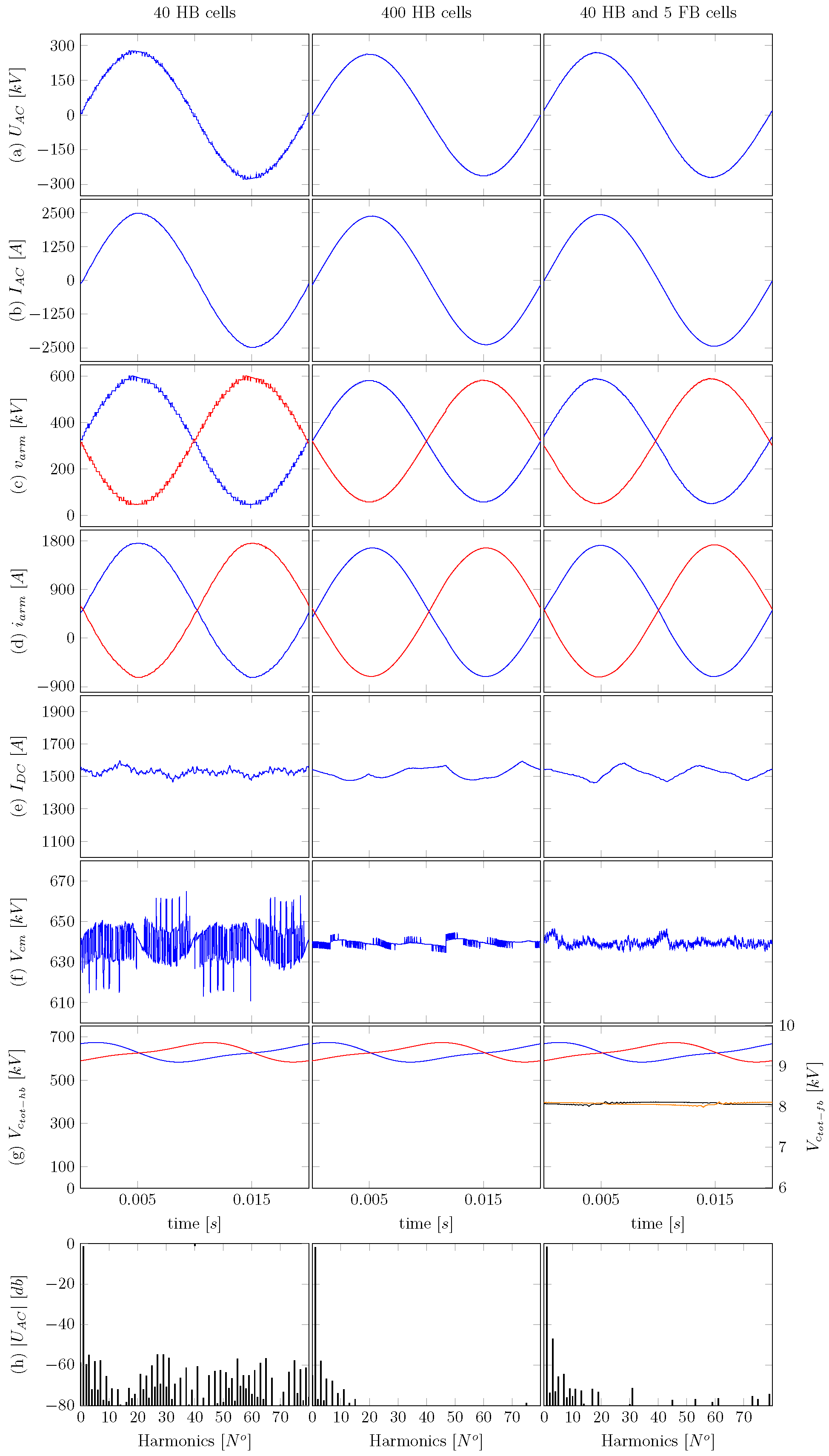
This section compares performance of the E M M C 40 + 1 against that of the conventional HB-MMCs with 40 and 400 cells per arms. The full-scale models used in this comparison were developed in EMTP-RV simulation platform, with parameters listed in Table 3. The M M C 40 and M M C 400 use LS-PWM and NLM, respectively, whereas both HB and FB chain-links of the E M M C 40 + 1 employ NLM. Figure 5 presents selected simulation waveforms of the M M C 40 , M M C 400 , and E M M C 40 + 1 .
The main observations from this comparative study are as follows.
  • The simulation plots in Figure 5a,b show that all the converters being compared present high-quality ac side output voltages and currents. The E M M C 40 + 1 , with only 40 medium-voltage HB cells (each rated at 16 kV) and five FB cells (each rated at 1.6 kV), generates an ac side output phase voltage with practical identical quality (THD and d v / d t ) as that of the HB-MMC with 400 cells, which each cell is rated at 1.6 kV, whereas the conventional 40-cell HB-MMC exhibits slightly inferior output ac voltage in terms of THD and dv/dt. Output phase ac voltage THDs of the M M C 40 , M M C 400 and E M M C 40 + 1 are 1.47%, 1.32% and 1.28% respectively). The output phase current quality of the three converters (Figure 5b) remains practically similar due to sizable arm inductors which act as filters to switching frequency harmonics in the arm and output currents (Figure 5d).
  • The total arm voltages displayed in Figure 5c confirm that the E M M C 40 + 1 is able to match the M M C 400 in terms of output voltage quality and d v / d t .
  • The dc link currents and common-mode voltages shown in Figure 5e,f show that the M M C 40 injects significant high-frequency harmonics into the dc side compared to M M C 400 and E M M C 40 + 1 . The dc voltage ripples of the M M C 40 , M M C 400 and E M M C 40 + 1 are 5.18%, 0.22%, and 0.25%, respectively. This is because the large cell voltage of the M M C 40 , 16 kV, leads to larger errors in the synthesis of the instantaneous common-mode voltage compared to that of the M M C 400 , which is 1.6 kV and of the E M M C 40 + 1 .
  • Figure 5g shows the upper and lower arms HB cell capacitor voltage sums of the M M C 40 , M M C 400 and E M M C 40 + 1 are well regulated around V d c = 640 kV and exhibit similar low-frequency ripples, whereas the E M M C 40 + 1 FB cell capacitor voltage sums remain well regulated at ~8 kV, which represent small portions of the HB cell capacitor voltage sums.
  • The output voltage spectra of the M M C 40 , M M C 400 and E M M C 40 + 1 displayed in Figure 5i show the improved harmonic performances of the M M C 400 and E M M C 40 + 1 relative to M M C 40 . These results confirm the significant improvement that th concept of nested multilevel operation brings.
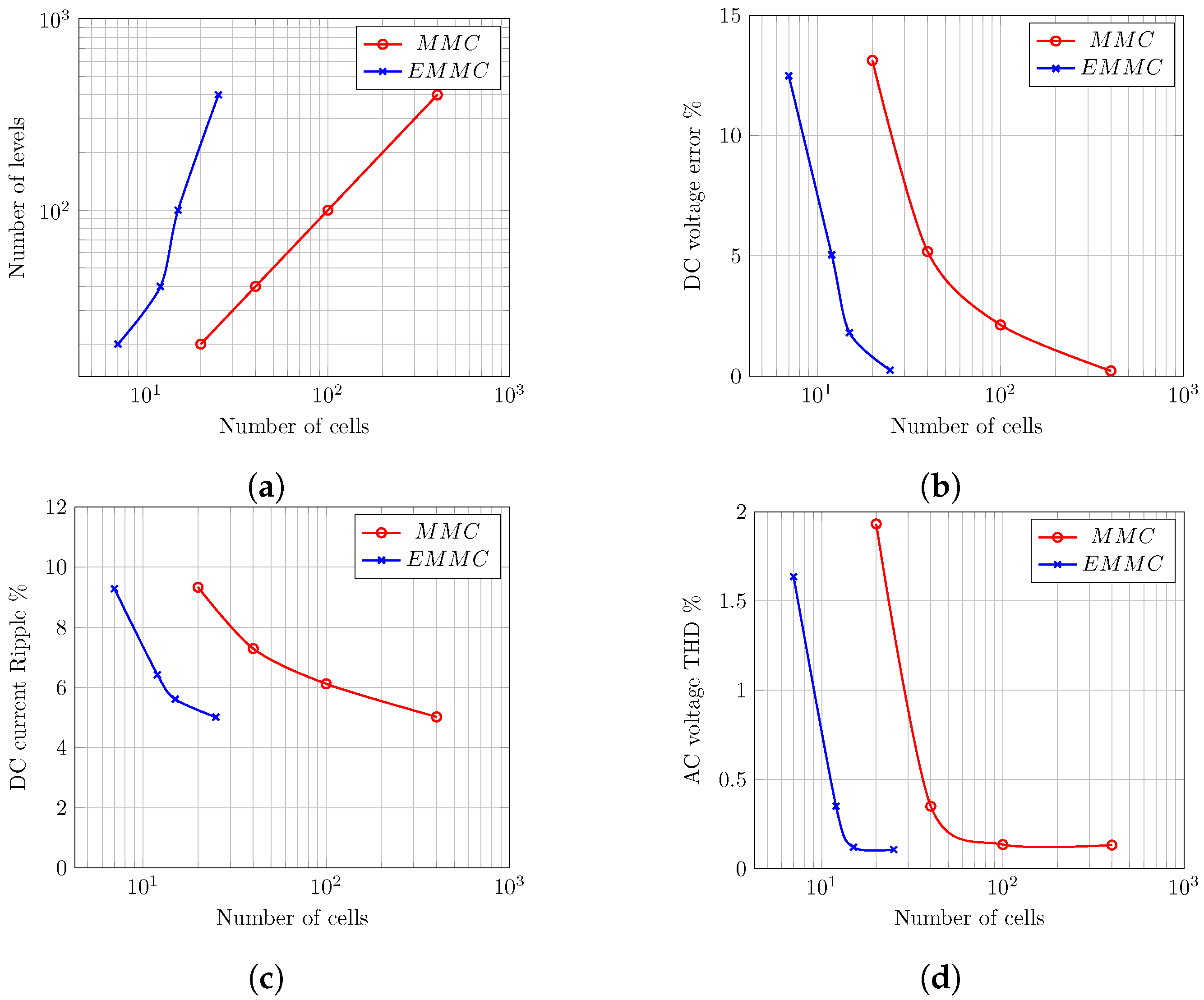
Figure 6a–d presents the overall summary of the comparative study between M M C 40 , M M C 400 , and E M M C 40 + 1 in the forms of graphical depictions of the relationships between number of cells, voltage levels per phase of output ac voltage, dc current and voltage ripples, and ac side voltage THDs. In summary, the general conclusion drawn from Figure 6 are as follows.
  • Figure 6a shows that the multiplication effect of nested multilevel operation allows the EMMC with few HB and FB cells per arm to generate the same number of voltage levels per output phase voltage as conventional HB-MMC with large number of cells per arm. For example, E M M C 4 + 1 , i.e., EMMC with N H B = 4 and N F B = 4, generate maximum of 33 voltage levels per arm or phase voltage, which is equivalent to HB-MMC with 32 cells per arm.
  • Figure 6b,c indicates that the dc voltage and current ripples drop significantly faster with the growth in the number of cells in the EMMC than in the conventional HB-MMC.
  • Similarly, the output voltage THD of the EMMC decreases quicker with increase in the number of cells than in the HB-MMC.

5. Conclusions

This paper presented the Enhanced Modular Multilevel Converter to address some of the shortcomings of the conventional HB-MMC with reduced number of medium-voltage cells, particularly, its relatively poor ac and dc side power quality. The EMMC utilizes a combination of MV HB cells and LV FB cells to institute nested multilevel operation, which dramatically improves the quality of ac and dc side waveforms. It has been shown that the EMMC has potential to reduce the power circuit complexity of the full-scale HB-MMC, which is extremely important from condition monitoring and protection of high value assets such as HVDC converters. The presented simulation and experimentation results show that the nested multilevel concept permits the EMMC with few number of MV-HB and FB cells per arm to generate high-quality ac and dc side waveforms, and large number of output voltage levels per phase compared to the conventional HB-MMC.
In summary, the particular contributions and novelty of this paper and key differences with previous modular and hybrid converters as follows.
  • This paper has proposed the EMMC to address the power quality shortcomings of the HB-MMC that employs reduced number of medium-voltage HB cells. Moreover, it has presented a novel nested multilevel operation to enable correct operation of the EMMC, and extra inter-arm capacitor voltage balancing controller to ensure the total voltage across the HB and FB chain-links of each arm are tightly controlled around the desired set-points.
  • Unlike the MC-MMC, the proposed EMMC uses the same number of medium-voltage HB cells in its arms as that of the HB-MMC equivalent, and it adds small number of relatively low-voltage rated FB cells into each arm. The total blocking voltage of each HB chain-link in the arm of the EMMC is equal to the full pole-to-pole dc link voltage, whereas the total blocking voltage of each FB chain in the arm of the EMMC is equal to half of the HB cell capacitor voltage. In way, the total semiconductor loss associated with incorporation of these additional FB chain-links is minimized.
  • The proposed nested multilevel operation concept allows the HB chain-link of the EMMC to synthesize the desired fundamental of the output voltage through rough stepped approximations of the arms voltages (which compose of fundamentals and dc offsets), with major voltage steps equal to the HB cell capacitor voltage, typically in order of 16 kV to 20 kV. On other hand, the FB chain-links of the EMMC facilitate fine and orderly stepped transitions (inter-step multilevel operation), with minor voltage steps equal to FB cell capacitor voltage (typically, ranging from 1 kV to 2.5 kV), between successive major voltage steps of the HB chain-links.
  • Unlike the MC-MMC, only HB chain-links of the EMMC contribute to the synthesis of common-mode voltage dc link voltage) and differential mode voltage (ac side voltage, including fundamental component of the arm or output phase voltage), while its FB chain-links operate as active power filters which generate anti-phase voltage harmonics to nullify the inherent harmonics in the parts of the arm voltages that the HB chain-links have synthesized. The few added FB cells into the EMMC arms have significant impact in reduction of errors in the synthesis of the common and differential mode voltages. In this way, the EMMC can match the performance of the HB-MMC that employs large number low-voltage rated cells, simply by small modifications to the power circuit of the HB-MMC and proposed nested multilevel concept.
  • The nested multilevel concept permits the EMMC to generate large number of voltage levels per phase or arm compared to the conventional modular and hybrid converters. For example, 640 kV dc link EMMC with 40 HB cells (each rated for 16 kV) and five FB cells (each rated for 1.6 kV) can generate 401 voltage levels per phase or arm, which is the same as HB-MMC with 400 cells (each rated for 1.6 kV). In this, case the total blocking voltage of HB and FB chain-links are 640 kV and 8 kV.
  • The MC-MMC was developed for improved dc fault tolerant operation, while the EMMC is not.

Author Contributions

Conceptualization: G.P.A. and D.V.; Methodology: D.V. and F.A.; Software: D.V. and F.A.; Validation: G.P.A. and Y.A.-T.; Formal Analysis: F.A. and G.P.A.; Investigation: D.V. and Y.A.-T.; Resources: F.A.; Data Curation: D.V.; Writing—Original Draft Preparation, D.V. and F.A.; Writing—Review Editing, G.P.A. and Y.A.-T.; Visualization: D.V. and F.A.; Supervision: G.P.A.; Project Administration: Y.A.-T.; and Funding Acquisition: F.A., G.P.A. and Y.A.-T. All authors have read and agreed to the published version of the manuscript.

Funding

This research was funded by the Deanship of Scientific Research (DSR) of King Abdulaziz University, Jeddah, under grant no. (RG-23-135-39).

Conflicts of Interest

The authors declare no conflict of interest.

References

  1. Dong, H.; Xu, Z.; Song, P.; Tang, G.; Xu, Q.; Sun, L. Optimized Power Redistribution of Offshore Wind Farms Integrated VSC-MTDC Transmissions After Onshore Converter Outage. IEEE Trans. Ind. Electron. 2017, 64, 8948–8958. [Google Scholar] [CrossRef]
  2. Alsokhiry, F.; Adam, G.; Al-Turki, Y. Limitations of voltage source converter in weak ac networks from voltage stability point of view. Int. J. Electr. Power Energy Syst. 2020, 119, 105899. [Google Scholar] [CrossRef]
  3. Henderson, C.; Vozikis, D.; Holliday, D.; Bian, X.; Egea-Àlvarez, A. Assessment of Grid-Connected Wind Turbines with an Inertia Response by Considering Internal Dynamics. Energies 2020, 13, 1038. [Google Scholar] [CrossRef] [Green Version]
  4. Oates, C. Modular Multilevel Converter Design for VSC HVDC Applications. IEEE J. Emerg. Sel. Top. Power Electron. 2015, 3, 505–515. [Google Scholar] [CrossRef]
  5. Rodriguez, J.; Bernet, S.; Wu, B.; Pontt, J.O.; Kouro, S. Multilevel Voltage-Source-Converter Topologies for Industrial Medium-Voltage Drives. IEEE Trans. Ind. Electron. 2007, 54, 2930–2945. [Google Scholar] [CrossRef]
  6. Zeng, R.; Xu, L.; Yao, L.; Finney, S.J. Analysis and Control of Modular Multilevel Converters under Asymmetric Arm Impedance Conditions. IEEE Trans. Ind. Electron. 2016, 63, 71–81. [Google Scholar] [CrossRef] [Green Version]
  7. Deng, F.; Tian, Y.; Zhu, R.; Chen, Z. Fault-Tolerant Approach for Modular Multilevel Converters Under Submodule Faults. IEEE Trans. Ind. Electron. 2016, 63, 7253–7263. [Google Scholar] [CrossRef]
  8. Friedrich, K. Modern HVDC PLUS application of VSC in Modular Multilevel Converter topology. In Proceedings of the 2010 IEEE International Symposium on Industrial Electronics, Bari, Italy, 4–7 July 2010; pp. 3807–3810. [Google Scholar] [CrossRef]
  9. Jacobson, B.; Karlsson, P.; Asplund, G.; Harnnart, L.; Jonsson, T. VSC-HVDC Transmission with Cascaded Two-Level Converters; CIGRE: East Lansing, MI, USA, 2014. [Google Scholar]
  10. Debnath, S.; Qin, J.; Bahrani, B.; Saeedifard, M.; Barbosa, P. Operation, Control, and Applications of the Modular Multilevel Converter: A Review. IEEE Trans. Power Electron. 2015, 30, 37–53. [Google Scholar] [CrossRef]
  11. Neeb, C.; Boettcher, L.; Conrad, M.; Doncker, R.W.D. Innovative and Reliable Power Modules: A Future Trend and Evolution of Technologies. IEEE Ind. Electron. Mag. 2014, 8, 6–16. [Google Scholar] [CrossRef]
  12. Nami, A.; Liang, J.; Dijkhuizen, F.; Demetriades, G.D. Modular Multilevel Converters for HVDC Applications: Review on Converter Cells and Functionalities. IEEE Trans. Power Electron. 2015, 30, 18–36. [Google Scholar] [CrossRef]
  13. Adam, G.P.; Abdelsalam, I.; Fletcher, J.E.; Burt, G.M.; Holliday, D.; Finney, S.J. New Efficient Submodule for a Modular Multilevel Converter in Multiterminal HVDC Networks. IEEE Trans. Power Electron. 2017, 32, 4258–4278. [Google Scholar] [CrossRef] [Green Version]
  14. Perez, M.A.; Bernet, S.; Rodriguez, J.; Kouro, S.; Lizana, R. Circuit Topologies, Modeling, Control Schemes, and Applications of Modular Multilevel Converters. IEEE Trans. Power Electron. 2015, 30, 4–17. [Google Scholar] [CrossRef]
  15. Zeng, R.; Xu, L.; Yao, L.; Williams, B.W. Design and Operation of a Hybrid Modular Multilevel Converter. IEEE Trans. Power Electron. 2015, 30, 1137–1146. [Google Scholar] [CrossRef] [Green Version]
  16. Dekka, A.; Wu, B.; Zargari, N.R. Start-Up Operation of a Modular Multilevel Converter With Flying Capacitor Submodules. IEEE Trans. Power Electron. 2017, 32, 5873–5877. [Google Scholar] [CrossRef]
  17. Mathew, E.C.; Ghat, M.B.; Shukla, A. A Generalized Cross-Connected Submodule Structure for Hybrid Multilevel Converters. IEEE Trans. Ind. Appl. 2016, 52, 3159–3170. [Google Scholar] [CrossRef]
  18. Zhang, J.; Zhao, C. The Research of SM Topology With DC Fault Tolerance in MMC-HVDC. IEEE Trans. Power Deliv. 2015, 30, 1561–1568. [Google Scholar] [CrossRef]
  19. Oliveira, R.; Yazdani, A. A Modular Multilevel Converter With DC Fault Handling Capability and Enhanced Efficiency for HVdc System Applications. IEEE Trans. Power Electron. 2017, 32, 11–22. [Google Scholar] [CrossRef]
  20. Yu, X.; Wei, Y.; Jiang, Q. STATCOM Operation Scheme of the CDSM-MMC During a Pole-to-Pole DC Fault. IEEE Trans. Power Deliv. 2016, 31, 1150–1159. [Google Scholar] [CrossRef]
  21. Vozikis, D.; Adam, G.; Holliday, D.; Finney, S. An Improved Alternate Arm Converter for HVDC Applications. In Proceedings of the IECON 2018—44th Annual Conference of the IEEE Industrial Electronics Society, Washington, DC, USA, 21–23 October 2018; pp. 3921–3925. [Google Scholar] [CrossRef] [Green Version]
  22. Vozikis, D.; Rault, P.; Holliday, D.; Finney, S. Fault blocking converters for HVDC transmission: A transient behaviour comparison. J. Eng. 2019, 2019, 3825–3830. [Google Scholar] [CrossRef]
  23. Qin, J.; Saeedifard, M. Reduced Switching-Frequency Voltage-Balancing Strategies for Modular Multilevel HVDC Converters. Power Deliv. IEEE Trans. 2013, 28, 2403–2410. [Google Scholar] [CrossRef]
  24. Saeedifard, M.; Iravani, R. Dynamic Performance of a Modular Multilevel Back-to-Back HVDC System. IEEE Trans. Power Deliv. 2010, 25, 2903–2912. [Google Scholar] [CrossRef]
  25. Harnefors, L.; Antonopoulos, A.; Norrga, S.; Angquist, L.; Nee, H.P. Dynamic Analysis of Modular Multilevel Converters. IEEE Trans. Ind. Electron. 2013, 60, 2526–2537. [Google Scholar] [CrossRef]
  26. Vozikis, D.; Adam, G.; Rault, P.; Tzelepis, D.; Holliday, D.; Finney, S. Steady-state performance of state-of-the-art modular multilevel and alternate arm converters with DC fault-blocking capability. Int. J. Electr. Power Energy Syst. 2018, 99, 618–629. [Google Scholar] [CrossRef] [Green Version]
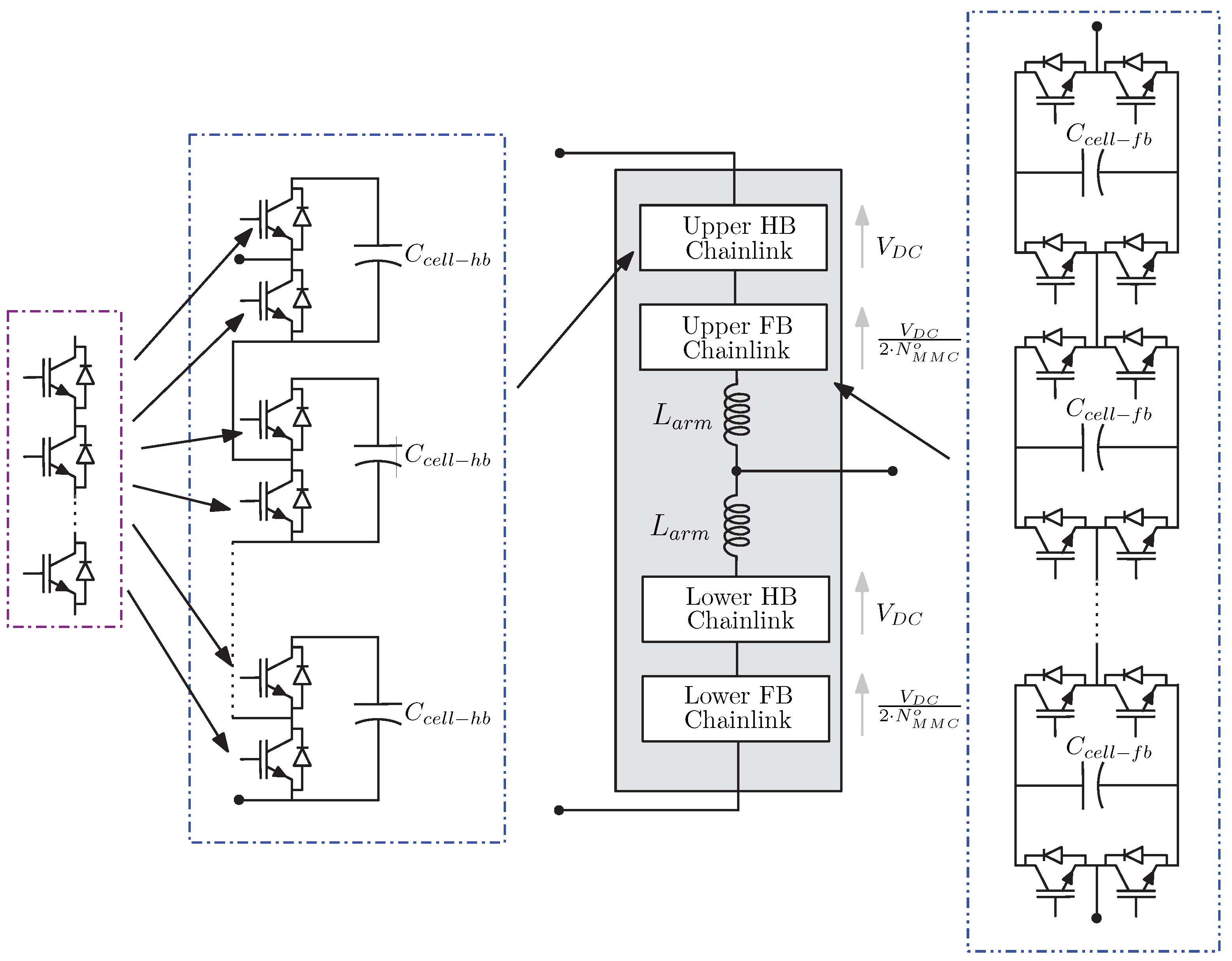
Figure 1. Phase representation of EMMC topology.
Energies 13 02257 g001
Figure 2. Phase representation of EMMC topology: (a) Operation during a full cycle and (b) detailed operation.
Energies 13 02257 g002
Figure 3. Modulation signals: (a) HB chain-link; (b) FB chain-link; (c) Detailed illustration of modulation signals.
Energies 13 02257 g003
Figure 4. EMMC experimental results: (a) HB chain-link voltage; (b) FB chain-link voltage; (c) HB chain-link total capacitor voltage; (d) FB chain-link total capacitor voltage; (e) total arm voltage; (f) common-mode voltage; (g) output AC voltage; (h) output AC current.
Energies 13 02257 g004
Figure 5. Waveform comparison between an HB-MMC with 40 (left column) and 400 (middle column) cells, and an EMMC with 40 HB cells and 5 FB cells (right column).
Energies 13 02257 g005
Figure 6. Scalability of EMMC compared to conventional MMC for various numbers of cells:(a) correlation between number of cells and number of levels produced in each arm, (b) common-mode DC voltage error, (c) DC current ripple, and (d) AC phase voltage THD.
Energies 13 02257 g006
Table 1. Semiconductor loss comparison between modular multilevel converters (MMC) and EMMC.
LossesConduction
[MW]
Switching
[MW]
Total
[MW]
M M C 400 S i I G B T 4.751.145.89
M M C 40 S i I G B T 4.751.756.50
E M M C 40 + 1 S i I G B T 4.971.356.32
E M M C 40 + 1 S i C M o s 5.081.146.22
Table 2. Converter specification.
V D C [V]300
R L O A D [ Ω ]17
N h b / N f b 4/4
f S [kHz]2.5
L a r m [mH]5
C h b / C f b / C f [mF]2.2/4.4/5
Table 3. HVDC specifications.
N o Cells N hb = 40 N hb = 400 N hb = 40
N fb = 5
HB chain-link modulationPWMNLMNLM
FB chain-link modulation--NLM
HB cell voltage [kV]161.616
FB cell voltage [kV]--0.8
HB cell capacitance [mF]1.3013.021.30
FB cell capacitance [mF]--6.51
P [MW]1000
V D C [kV]640
L a r m [p.u.]0.05