Abstract
In this work, we describe the design and test of a new piece of equipment, developed in order to enhance speed, gas consumption and safety during the manual asphalt roofing process. The novelty of the equipment is based on the use of a set of five parallel gas burners located in front of the roll to maximize heat transfer. The equipment is light and can be used by any worker on any type of roof. It also includes a thermal insulation cover to significantly reduce gas consumption and, thus, to reduce CO2, SO2, and other non-eco-friendly emissions. In this paper, we present the mechanical and thermal design and analysis of the equipment, Computer Fluid Dynamics (CFD) simulations for heat transfer calculation, a description of the manufacturing and assembly, a preliminary thermal test, and an operational test. The results demonstrate an installation speed of 1.75 m2/min, for 3 kg/m2 rolls, which translates to around 700–735 m2 per person per day, more than twice the usual manual roofing rate. Nevertheless, some issues need to be resolved, such as the nonuniform heat distribution and the low heat transfer at the end of the roll installation.
1. Introduction
Nowadays, roofing methods play an essential role in the energy efficiency and weather resistance of buildings and houses [1]. One common roof protection method is to install asphalt coatings. Specialized workers generally do asphalt roofing manually. They typically carry a single Liquefied Petroleum Gas (LPG) burner to apply the heat to the rolls. Workers perform several steps when roofing: locating the rolls, aligning them with respect to the previous rolls, unrolling them, applying heat, and finishing them off. A worker can install around 20–25 rolls per day (200–250 m2) using this manual procedure. Such a reduced capacity for manual installation has motivated patents and developments of new systems and equipment to facilitate and enhance roll installation speed.
Patent EP0466249 [2]—a method and apparatus for applying a bituminous sheet to a substrate—presents a roller system with a previously heated additional drum wherein the asphalt roll is heated. Another patent US4725328 [3] was claimed for a mechanism that includes two heating torches perpendicular to the roll. Heating torches were located at both ends to increase adherence where the rolls overlap. Patent US 2013228287 [4] has been commercialized using the name Unify-ER by the company RES Automatisation Contrôle [5]. This device applies heat to the roll through a longitudinally distributed set of LPG burners. This equipment shows a roll installation speed of 1 m/min, claiming a rate of 18 rolls per hour, but requires two workers; thus, this device provides an installation of 480 m2 per day per person. Although it is faster and much more efficient than the manual technique, the large number of frames, structure and auxiliary mechanisms leads to a total weight of 180 kg. Such a high weight considerably hinders its use on weak roofs. In addition, the excessive size of the equipment makes it difficult to be transported in small vans. Other commercial equipment are the Seal-Master 1030 from Schäfer Technic GmbH and the Bitumenbrenner from Bamert Spenglerei GmbH. From a practical point of view, the main disadvantages of all the previous systems are that they are heavy, too large for operation on small roofs and difficult to transport. On the other hand, manual installation only requires a single torch and propane bottle. The lightweight equipment that we present in this article provides a fast, high quality application capacity, while being light and small enough to be transported and used in most cases.
All previous patents and products enhance asphalt roofing speed but they all require gas burners to heat the asphalt up for its installation. Gas burners generate CO2 and SO2 emissions, which must be reduced as much as possible. Roofing has attracted the attention of environmental administrations in order to reduce their emissions. For example, the Asphalt Roofing Manufacturing Association (ARMA) developed emissions factors for asphalt-related air emissions for all the relevant processes in the manufacture of roofing asphalt [6]. Moreover, a measurement of 75.2 kg CO2eq per roll was estimated in [7] and the installation stage in buildings was found to be responsible for the majority of those emissions. Infrared heating could be an alternative option to gas burners [8], but its applicability is limited to places where a high electrical power source is available. Therefore, it is necessary to reduce the gas consumption as much as possible by optimizing the heat transfer from torch burners to asphalt rolls.
Besides speed and gas consumption, roofing workers’ health must also be guaranteed and protected. When doing manual installation, workers often do not use safety prevention equipment in order to improve their speed, at the expense of increasing the risk of accidents. A proper way to prevent occupational illnesses, injuries and fatalities is to design systems and equipment that allow workers to operate efficiently [9]. Moreover, inadequate posture during manual roofing may cause a rise in the number of illnesses and injuries. The equipment presented in this article allows workers to operate in safer conditions and to prevent work injuries. We hope that the equipment presented in this article will help workers during manual installation, reduce installation risks, increase installation speed, optimize gas consumption and will be light and practical for use on any type of roof. Furthermore, the shorter the installation time of the asphalt rolls, the lower the CO2 emissions; thus, the presented equipment even provides an improvement in the human factor because, during the installation of asphalt rolls, humans are also a source of emissions (eating, creating waste, using electricity, etc.), and the impact of their emissions decreases if the working time is reduced.
The presented equipment consists of a lightweight trolley mechanism that allows the installation of asphalt rolls in a quicker, cleaner, and safer way. This trolley includes a set of five parallel torches located in front of the roll to heat the asphalt up. Asphalt rolls are directly placed on the floor, so the worker does not have to lift them. As the worker pushes the trolley, auxiliary wheels unroll the roll, while the worker can control the heat application. The equipment also includes an insulation cover to maintain and increase the heat transfer from the torches to the roll. This allows for the uniform and continuous heating of the roll for its installation on the ground, which is synchronized with the unrolling. Moreover, the trolley has two small compaction drum rollers in both lateral sides, in order to assure the adherence of the asphalt where the rolls overlap.
In this article, we present the mechanical and thermal design and an analysis of the equipment, CFD simulations for the calculation of heat transfer, a description of the manufacturing and assembly, a preliminary thermal test, and an operational test of this new equipment, demonstrating the claimed advantages. To conclude, we include a list of lessons learned after the tests that may help to improve the equipment in further developments.
2. Design and Analysis
The described lightweight equipment is basically a lightweight trolley design that facilitates the installation of asphalt rolls. This equipment is composed of the following elements: a light trolley structure, four wheels for the motion of the trolley, an auxiliary wheel for unrolling the asphalt roll, a set of five torches aligned parallel to the roll, a top thermal insulation cover to avoid heat loss, small drum rollers for the compaction of the asphalt in the overlaps and general gas flow regulators and switches.
2.1. Mechanical Design and Analysis
Figure 1 compiles three views of the trolley. The isometric view shows the trolley (1), which can be pushed using a handle placed at a comfortable height for the worker. A total of four wheels (3) allow for the smooth motion of the equipment. The rear wheels are blocked and the front wheels are free to allow steering, so that the worker can precisely drive and guide the trolley. The asphalt roll (4) is located inside the main frame. The trolley has two locating stops on both laterals to keep the roll in the right position and allow for the re-direction of the roll while it is being unrolled. In addition, the trolley has two auxiliary wheels (5) located behind the roll, and at a height lower than the radius of the roll. These auxiliary wheels transmit the pushing force tangentially to the roll. A thermal insulation cover made by rock wool (6), which maximizes the heat transfer, covers the whole roll. Additionally, the trolley includes two small drum rollers (12) for the compaction of the asphalt where rolls overlap.
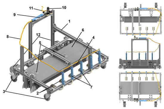
Figure 1.
Isometric and orthogonal views of the design: 1—trolley, 2—torches, 3—wheels, 4—asphalt roll, 5—auxiliary wheels, 6—thermal insulation cover, 7—individual flow regulator, 8—gas pipeline, 9—on/off valve, 10—main flow regulator, 11—main pipeline from propane bottle, 12—drum rollers.
Figure 1 also shows the set of five torches (2), which are parallel and aligned in front of the asphalt roll. A flexible pipeline (8) connects all the torches with the main gas pipeline. Each torch flow can be individually regulated (7), but is also regulated by a general flow regulator (10) placed close to the handle. The activation of the torches is set and controlled by an on/off manual control valve (9). The gas is provided from a propane pressurized bottle through a flexible ten-meter-long pipeline (11).
The equipment is specially adjusted for ten-meter-long, one-meter-wide 3 kg/m2 asphalt rolls. The main dimensions are depicted in Figure 2. Smaller roll sizes could be compatible with the equipment, but the positions of the locating stops may be modified, placing larger or shorter limits on the rolls. For wider rolls, modifications to the whole structure would be necessary, as well as the repositioning of the torches. The total trolley mass is 16 kg, excluding the compaction drum rollers.
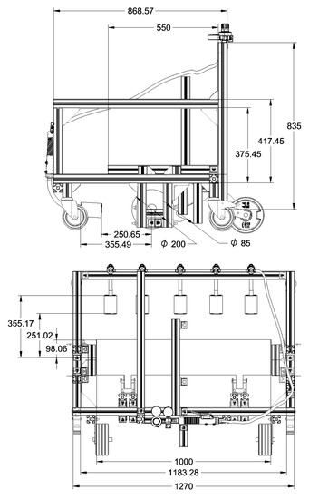
Figure 2.
General dimensions of the equipment in millimeters.
During installation, it is not necessary to lift the roll from the ground, since the trolley directly moves and unrolls it. Hence, there is no need to add heavy auxiliary rolls for unrolling, which makes the entire system much lighter and saves workers’ energy. The unrolling mechanism and structure of the trolley follows the design shown in [10] and the patent in [11]. The mechanism is based on a pair of auxiliary wheels.
Standard 3 kg/m2 asphalt rolls weigh 30 kg and are 0.25 m in diameter. The friction coefficient between concrete and asphalt is estimated as µ = 0.4. Thus, with a maximum friction force of F = µ·m·g = 117.6 N, almost 12 kg of horizontal pushing force is needed. Such a value is easily achievable for a construction worker. This implies that there could be an issue—if the trolley directly pushes the roll, the worker might be able to slide the roll without unrolling it. This could be severely problematic at the start of the installation of the roll because, at this point, there is no adherence between the asphalt and ground. One solution to prevent sliding is to include auxiliary wheels in order to facilitate unrolling. These auxiliary wheels permit the conversion of the horizontal thrust into a tangent force, making the unrolling much easier.
2.2. Thermal Design
One of the principal issues during manual installation with a single torch is that the heat flux is only applied in a highly localized area. With just one torch, heat has to be applied progressively along a single area on the roll. This leads to nonuniform adhesion and problems in the overlapping areas. The uniformity can be improved by using a longitudinal five-torch layout, meaning that heat is uniformly distributed along the roll line. The heat power required for this fast installation method is calculated in Section 2.2.1.
Additionally, the localized heat transfer is dependent on the desired length of application, which is variable, as it is controlled by the worker. When performing manual installation, the heating time is usually much longer than required for a proper asphalt installation. Workers do not have any way to measure or control of the temperature beyond their own eyesight and experience. By fixing the distance between the roll and the torches and by adjusting the gas flow of the torches individually and generally, workers can perfectly control the amount of heat that is applied. The gas pressure and torch selection were calculated through an iterative process, with transient CFD simulation results. CFD analysis determined the percentage of heat transferred to the roll, as shown in Section 2.2.2.
Moreover, in the manual method, the torches’ efficiency is reduced because most of the heat is lost due to the large environmental air convection that occurs far from the roll. In our model, we include a thermal insulation cover between the roll and the air flow, which forces the hot air to remain closer to the roll, increasing efficiency and reducing thermal losses. The effect of including this thermal insulation cover is quantified by a transient CFD analysis, which is also described in Section 2.2.2.
2.2.1. Requirement of Heat Power into the Roll
In order to select adequate torches and to adjust the gas flow consumption, it is necessary to first determine the necessary heat power that needs to be transferred to the roll for fast and adequate asphalt adhesion with the ground. However, before total heat, we have to determine the temperature the asphalt needs to reach for correct adhesion. This temperature can be set by analysing the viscosity behaviour of the asphalt with respect to temperature. The asphalt viscosity decreases asymptotically when the temperature increases [12]. With a value of 140 °C, the viscosity is lower than 125 mPa·s, which is very close to the final asymptotic value. As the asphalt’s bonding with the ground is based on its viscosity, 140 °C could be considered a hot enough temperature point for asphalt–ground bonding. The physical properties of asphalt and rock wool are shown in Table 1 [13].

Table 1.
Physical properties of asphalt and rock wool.
Thus, a rough first attempt was carried out, assuming no heat loss. The total power needed to heat up 1.75 m2/min of a 3 kg/m2 asphalt roll can be calculated as the necessary power to bring the complete mass from an initial temperature of 22 °C to a final temperature of 140 °C:
The environmental temperatures that can be found at workplaces can vary from 4 °C to 40 °C. For these conditions, the calculation returns the total power as 11.9 kW in the extreme case of an environmental temperature of 4 °C. Therefore, we consider the value of 11.9 kW to be the maximum total heat power needed.
During the second heat power calculation iteration, we have to take into consideration that asphalt rolls are made by consecutive asphalt layers. Hence, the heat applied to the roll does not only heat the first layer up, but it is transferred internally to the rest of the layers. This fact must be carefully analysed, since adhesion between layers must be avoided. Therefore, the temperature increase has to be sufficiently fast to maintain the installation speed, but slow enough not to make the layers adhere to one another. Accordingly, it is more accurate to determine an adequate temperature profile for the layers that is higher than the temperature of the asphalt. In this analysis, we will follow the same criterion used in the previous article [10]. This criterion is that the top surface temperature of the layer must be above 140 °C, the middle section of the layer must be at least 110 °C, and the interlayer point must be lower than 70 °C. In our previous work [10], we reached this point after 35 s when applying 11.73 kW/m2 for a total installation speed of 1 m2/min; if we target 1.75 m2/min, then we should transfer at least 20.52 kW/m2 to the roll (directly proportional to the calculation from [10], finite elements models results) in order to move the trolley at the targeted speed.
2.2.2. Heat Transferred and Thermal Insulation Cover
The next step in the thermal design is to estimate the heat percentage transfer from the hot combustion products coming from the torches to the actual roll. Two-dimensional CFD analysis has been used in order to determine the heat transfer efficiency for the exact geometry of the system, including the thermal insulating cover. Simulations have been set-up and solved by using CFD software ANSYS FLUENT software 2019 R2 (ANSYS, Inc, Canonsburg, PA, USA).
The geometry for the simulations is shown in Figure 3. The dimensions of each geometry correspond with the real prototype dimensions. This 2D geometry includes several boundaries:
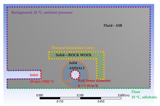
Figure 3.
CFD simulation geometry and boundaries.
- The background boundary considers a zero static pressure and an infinite ambient temperature of 25 °C;
- The inlet boundary supplies air a certain input speed, vi, and input temperature Ti;
- The thermal insulation cover boundary is a solid–fluid interface line that links the thermal properties of adjacent fluids with the solid thermal conduction inside the rock wool (the fluid speed in this boundary shall be zero). This boundary is removed in the second simulation in order to quantify the improvement effect of the thermal insulation cover;
- The roll boundary is a solid–fluid interface line that links the thermal properties of adjacent fluids with the solid thermal conduction inside the asphalt (the fluid speed in this boundary shall be zero);
- The inner diameter of the roll is a thermal convective boundary with a free convective coefficient of 5 W/m2K, which evacuates the heat to 25 °C ambient temperature;
- The floor is a wall-type boundary, which means that the fluid speed in this boundary shall be zero.
The inlet boundary length is 57 mm, which corresponds with the output geometrical diameter of the selected torches. The selected blowtorches are 70 mm in diameter and 58 kW of thermal power from company ECD-Germany (Neunkirchen-Seelscheid, Germany). This torch, shown in Figure 4, can provide up to 58 kW of thermal power with a propane consumption of 4000 g/h, at 4 bar of propane pressure in the gas pipeline orifice.
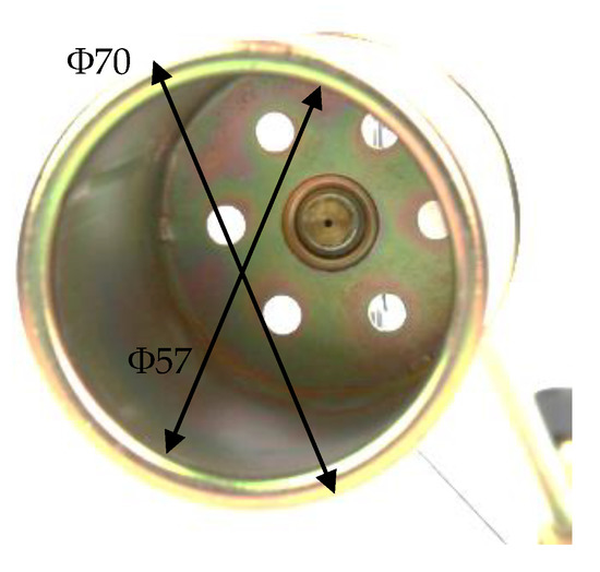
Figure 4.
Torch (70 mm in diameter) from Neunkirchen-Seelscheid, Germany.
The inlet boundary fluid conditions are the inlet speed vi = 10 m/s and the input temperature Ti = 1950 °C. The temperature of the flame at the ignition point is 1950 °C, as demonstrated for full propane combustion [14]. The inlet speed was selected after the preliminary laboratory tests. These kinds of assumptions must always be validated during the test phase [15], as we did in this study.
In the 2D CFD model, the extrapolated inlet area is the length of the inlet boundary line multiplied by a 1 m width, which makes a rectangle. This does not correspond exactly with the real model, which uses five circular torches. However, the objective of the 2D CFD analysis is to determine the relative percentage of transferred heat. In any case, both the thermal input power and the thermal transferred power are calculated per unit length. The thermal input power can be calculated as:
where is the air density at the case temperature , is the inlet speed, is the effective output diameter of the torch 57 mm and is the isochoric specific heat capacity of air when the temperature is . All values are expressed in international units. The thermal input power remains constant at each simulation time step.
The mesh element size is 0.004 m for most of the model, excluding the roll surface wherein the mesh is two orders smaller. The transient model was set up to solve the fluid–solid interaction in transient conditions. The air properties (density, cp, thermal conductivity and viscosity) were defined using a table as a function of the temperature, and the properties of the asphalt roll and the rock wool sheet as the constant values. For the model solver, the method and boundaries were: pressure-based, y-axis gravity, energy equation, standard k-epsilon, initializations of atmospheric pressure and 25 °C. The simulation time was set to 0–60 s. A constant time step of 0.1 s as set. Each time step simulation typically converged after 120 iterations in an Intel Core i5-9600K computer with 16 Gb of RAM, taking around 30 s for each step simulation. The complete transient simulation was done with and without thermal insulation cover.
The results of the air velocities for a time of 15 s with and without the thermal insulation cover are shown in Figure 5. For the result with the cover, it can be observed that most of the air flow goes between the middle height and the top cover, lifted up because lower density of the gas. Lower air speeds appears in the front-bottom part of the roll. The flame tends to rise at any moment. It can also be seen that the design with the cover increases the contact area between the hot air flow and the back of the roll. In the design without the cover, the air speed on the back of the roll is almost zero, and therefore the heat transmission in this area is very low.
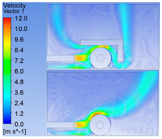
Figure 5.
CFD results: velocity distribution with cover (top) and without (bottom), time = 15 s.
The results of the temperature distribution for a time of 15 s with and without the thermal insulation cover are shown in Figure 6. For the result with the cover, it can be observed that the cover acts as an oven, making the hot air remain close to the roll. It is also relevant that a column of hot air rises from the bottom, which could affect the worker. Because of the lower density, the flame appears to rise at any moment. It can also be seen that the design with the cover increases the contact area between the hot air flow and the back of the roll. In the design without the cover, the temperature on the back of the roll is almost ambient and, again, we can expect that the heat transmission in this area will be very low. The area affected by hot temperatures can be estimated to be around 75% of the total roll area when using the cover and around 55% of the total roll area when not using the cover.
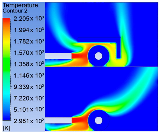
Figure 6.
CFD results: temperature distribution with cover (top) and without (bottom), t = 15 s.
The details of the temperature evolution inside the roll with and without the cover are shown in Figure 7. The figure presents the temperatures at three different points, t = 5, 10 and 15 s. Again, it is clear that the back of the roll was heated differently depending on whether the cover was present. It is important to note that the colour scale corresponds to the temperature profile criteria described in the previous subsection. The roll should, at least, be above 70 °C (yellow contour) to guarantee a successful adhesion. Moreover, we included a black circumference, indicating the position of the second bitumen layer of the roll. In this way, we can determine whether the first and second layer interfaces are hot enough to be installed.
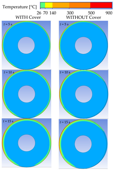
Figure 7.
CFD results: temperature inside the roll, with cover (left) and without (right).
It can be observed that, with or without the cover, the increase in the temperature on the front of the roll is almost the same. If t = 10 s, the first layer would be within the yellow contour and, therefore, it would be ready for installation. However, the back of the roll behaves differently with and without the cover. Without the cover, the back of the roll does not get hot enough, even if t = 15 s. Therefore, we conclude that using the cover will surely speed up the installation process. By using the cover, we can determine that around 75% of the exposed roll area is ready to be installed after 15 s; this means that a total area of 0.031 m2/s or 1.88 m2/min was aimed for in the prototype.
The heat transferred inside the roll, with and without the cover, as a function of time is shown in Figure 8. With the cover, the heat transferred was calculated to be around 20 kW. This coincides with the estimated requirement of the previous subsection, but the objective of the 2D model is to estimate the percentage of heat transfer and not the total transferred heat. Notably, the heat transfer rate decreases with time. This can be explained because, as the roll gets hotter, the total heat transfer is reduced until it reaches a certain stationary asymptotic value. The heat transferred without the cover is around 75% of the heat transferred with the cover, which was expected based on the temperature distribution analysis.
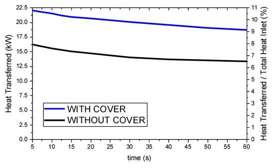
Figure 8.
CFD results: heat transferred to the roll and relative percentage with respect to total heat inlet, with cover (left) and without (right).
However, when comparing the total heat transferred to the roll with the total heat generated, the values are low. It has been determined that only around 10% of the total generated heat will be transferred to the roll. This implies that the system shall generate a total heat of around 205 kW. Each torch shall generate up to 41 kW. If one torch has the capacity to generate 58 kW of thermal power with a consumption of 4000 g/h, at 4 bar of propane pressure, then it means that the system should operate with a pressure of 2.8 bar and a consumption of 2800 g/h per torch.
3. Manufacturing and Assembly of the Prototype
The prototype was assembled following the design described above. Normalized 45 × 45 aluminium profiles make up the main structure. Although they are not the optimal solution in weight terms, their use allowed for the realization of quick and small modifications and/or adjustments to correctly fit the rest of the parts. The main frame and auxiliary wheel mechanisms of the prototype are assembled together, as shown in Figure 9. The insulation cover was manufactured at Universidad de Alcalá workshop using 1-mm laminated stainless steel for the coating and 40-mm-thick rock wool as internal insulation material. The thermal isolation cover is mounted above the frame, and the lateral stops are adjusted in order to keep the roll within the trolley and to limit the degrees of freedom when unrolling. Five torches are mounted and equally spaced in the front, pointing toward the auxiliary wheel, as shown in Figure 9. The gas flow pipelines, flow and pressure regulators are connected and assembled on the trolley.
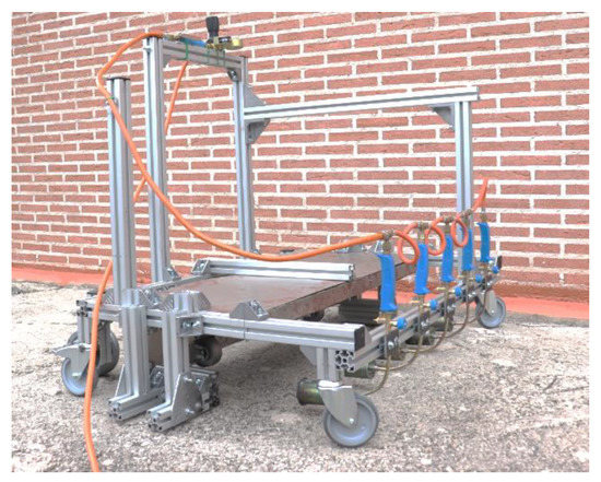
Figure 9.
Real prototype assembled.
The overlap compaction drums are connected to the main frame through a bi-articulated connecting rod, as shown in detail in Figure 10. Drums are 10 cm wide and they are aligned in order to press the 10-cm-wide area required for the overlaps. Each compaction drum is constructed using four 2-kg weights jointed by a connecting axle. This axle can rotate around the linking rod, which can also rotate around the main frame. This allows for the continuous vertical pressing of the weights against the ground, compacting the asphalt overlaps with the subsequent asphalt roll.
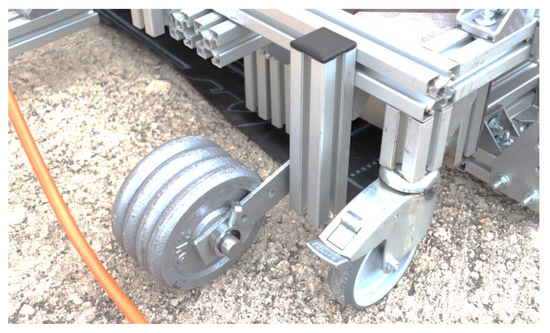
Figure 10.
Compaction drum at the bottom of the trolley.
The gas circuit scheme is depicted in Figure 11. The gas circuit starts from the propane bottle, which is linked through a free output regulator to a manual pressure regulator. The propane bottle provides gas at a pressure between 2 and 6 bar. During tests, the propane bottles provided 5 bar to the manual pressure regulator, as shown in Figure 12. The manual pressure regulator allows us to control and regulate the pressure reaching the torches. In the diagram shown in Figure 12, the output pressure was limited to 2.8 bar. Once the pressure is regulated, the flow can be controlled and modulated through an on/off valve which also has a second flow regulator. In the case of the prototype, this second flow regulator was fully open and so the activation or deactivation of the torches could be achieved using this on/off valve, which is also shown in Figure 12.
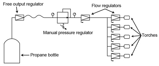
Figure 11.
Schematics of gas circuit.
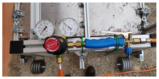
Figure 12.
Manual pressure regulator and on/off valve.
The main pipeline is connected to the manual pressure regulator by a 1/4” Left Handed (LH) nut connection. The pressure regulator is linked to the on/off valve with a shortcut using a 3/8” LH nut attached to a 3/8” LH screw. The on/off valve is linked to the torch pipeline using a 3/8” LH nut connection.
The pipeline distributes the gas flow to the five torches through a T-type 3/8” LH connector. Each torch has its own flow regulator, as shown in Figure 13. This allows for individualized heat flow adjustment. This can be useful for increasing heat flow in the two torches that heat the overlaps, since these areas are critical to ensure the impermeability of the roof. Torches are mounted in parallel at the distance and height depicted in the dimensional drawings in Figure 2.
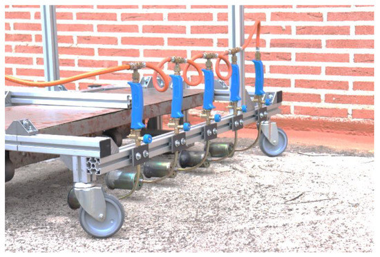
Figure 13.
Individual flow regulators and parallel torches.
In order to initiate the installation, the roll must be placed inside the trolley, in contact with the auxiliary wheels and between the lateral stops. The steps for placing the roll are to leave the roll on the ground and to front-lift the trolley using the rear wheels. The trolley has a little aluminium profile-made pedal, shown in Figure 12 next to the feet, which helps to lift the trolley when the worker steps on it. Then, the trolley is pushed against the roll to ensure contact against the auxiliary wheels, as shown in Figure 14. The asphalt roll has to be prepared and located in the proper position in order to overlap any previously installed asphalt. Furthermore, the surface has to be prepared before the installation. For this, we applied ChovASTAR® waterproofing surfaces preparer on the surface, which is a liquid product formed by resins and bitumen in aqueous solution. This product drastically improves the adherence between the ground and the asphalt roll. Once the preparer is applied and the roll is in position, installation can start.
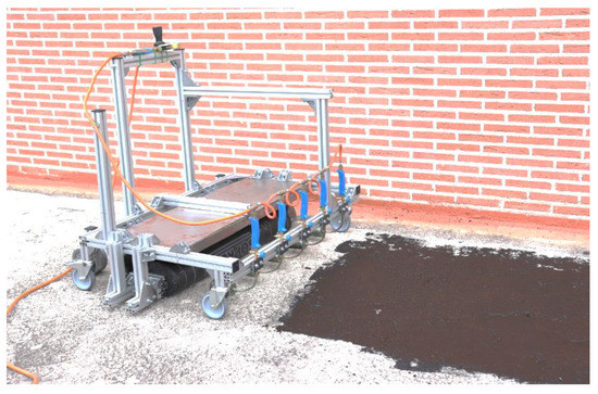
Figure 14.
Prototype and surface ready for asphalt roofing.
4. Test Results and Discussion
The test campaign is planned and executed in order to determine the real capacity, speed and equipment performance after installation. Preliminary laboratory tests are used to validate some considered assumptions during the design phase, such as inlet input speed.
4.1. Preliminary Laboratory Test
A preliminary torch flow analysis test was conducted in order to estimate the hot air flow temperature and speed. In addition, the propane consumption was measured during this test. We supplied propane to the torches by using two propane bottles, delivering the gas at a pressure of 5 bar. The pressure that reached the five torches was limited to 2.8 bar, with a consumption of 2800 g/h per torch. We activated the five torches at their maximum flow capacity; flow regulators were fully open.
The air-fed propane flame is shown in Figure 15. Air enters to the torch from the bottom, where there are five holes 8 mm in diameter. Air is mixed with propane inside the torch. Torches must be manually ignited. Once the ignition occurs, the flow can be controlled individually at each torch. Figure 15 (top) shows the different zones of the flame shape. A blue flame means the complete combustion of the gas. Pure hydrocarbons like methane (refined natural gas), propane, butane and ethane gases also burn with a blue flame. The flame turns blue at the output of the torch, which means that air reaches a temperature between 1800–1980 °C for propane [14]. In the second zone of the flame, which is yellow, temperatures are lower, at 500–750 °C. This is the temperature of the air when it encounters the roll. There is a zone where the combustion becomes incomplete due to the absence of gas.
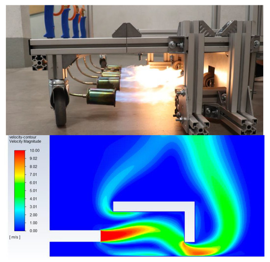
Figure 15.
Flow and consumption test of the five torches, photograph and validation CFD analysis—speed results.
Air speed has been estimated at around 10 m/s by using the CFD 2D model. In this case, the CFD model did not include the roll. CFD stationary simulations return flame shapes similar to the one we observed in the test. It is interesting to notice that the cross section of the flow is slightly smaller than the torch diameter and it is oriented to the upper part. This is due to the lower density of the outlet air already present in the torch. Thus, the CFD inlet temperature and air speed conditions can be considered reasonable, although it is important to note that CFD considers air as fluid, which is not exactly the case in reality, because combustion products do not have the same properties as air.
4.2. Outdoor Asphalt Temperature and Adhesion Test
Once the temperature and speed of the hot air flow have been determined in the laboratory, the outdoor installation tests must begin. Tests were carried out on the rough roof of an individual parking structure located in Torres de la Alameda (Spain). Several rolls and the prototype were transported to the location. The preparer was applied and the roll was put in position. Then, the torches were activated using a manual lighter. One person was in charge of moving the trolley and activating the on/off valve in order to apply the heat. Thermal images of the roll were taken using an infrared Fluke Ti32 thermal camera.
Figure 16 shows the torches in operation at a pressure of 2.8 bar and the temperature achieved on the roll surface after 10 s of application. It can be observed that almost half of the roll surface was above 200 °C, which is high enough for adhesion. The temperature was even higher on most of the surface (white areas), while it was slightly lower in the fringes created between the flows of consecutive torches. The total asphalt distance ready for adhesion after 10 s of heating was approximately 0.314 m, which equates to a 0.0314 m/s or 1.8 m/min targeted speed for the equipment.
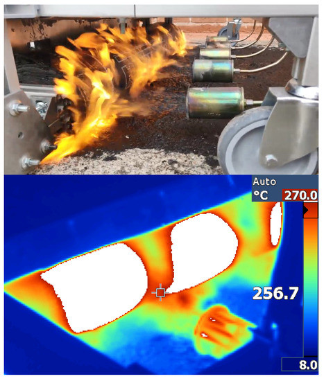
Figure 16.
Torches applying heat to the roll and corresponding infrared thermal image after ten seconds of application.
It is also necessary to analyse the temperature of the layer when it goes out the heating and how is its adherence with the ground. The trolley has to be moved in a step-by-step way, taking care that all the areas are heated.
The adhesion results, after the heating phase, are shown in Figure 17. The asphalt is clearly softer, which indicates a good adhesion at the bottom. The exerted pressure by the compaction drums is shown in the overlaps, where the grooves from the weights can be clearly seen. The thermal picture shows the temperature of the layer when it is adhered, in the range from 90 to 40 °C. We must consider that the surface shown in the figure is not the surface that receives the heat, but is the bottom face of the layer. Temperature differences between along the roll area appear because the heat application is not entirely uniform. There are spaces between torches that affect the uniformity of the heat distribution. This is something that could be improved by adding more torches or using wider diffusors on each torch. In any case, we believe that the layer is correctly installed.
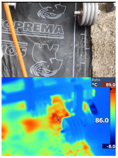
Figure 17.
Detail of the adhered layer in the overlaps areas and corresponding thermal image.
From this experience, we determined that a proper method for the installation of the roll consists on, first, to sustain heating at maximum capacity, and then to move the trolley. More specifically, the operation is to activate the on/off valve for 10 s, and then move the trolley forward by approximately 0.3 m.
4.3. Outdoor Installation Speed Test
Following the defined installation method, we performed the installation of several adjacent rolls, as shown in Figure 18. During the continuous installation, we realized several problems that may limit the actual installation speed. One important issue is the fact that, as the roll gets installed and unrolled, the distance between the torches and the roll increases, negatively affecting the amount of heat transferred. This implied that we must move slower towards the end of the installation of the roll. Another significant issue appeared when wind started to blow. This significantly reoriented the torches’ hot air flow, limiting the heat transfer. Adding some lateral walls may reduce the effect of external wind on the flows. Nevertheless, we reached an installation speed of approximately 1.75 m2/min with a torch pressure of 2.8 bar and a corresponding consumption of 2800 g/h of propane per torch.
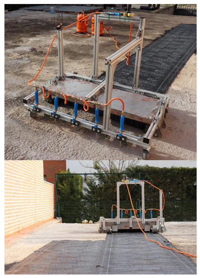
Figure 18.
Asphalt rolls installation results.
4.4. Outdoor Installation Quality Test
The rolls obtained good adhesion on most of the surface. In addition, the overlaps, which must be completely adhered to each other in order to ensure isolation, were adhered perfectly, one over the other, assuring the waterproof properties of the roofing, as shown in Figure 19. We observed that the compression by the compaction drums was really effective and, in these areas, the adhesion was better than in the middle, where no pressing besides the worker’s steps occurred. A potential improvement could be to add extra compaction drums all along the trolley. This will surely improve the adhesion in the middle, although the preparation of the trolley would be more difficult. In any case, the driving of the trolley would not be much more difficult, since the weight of the drums is not supported by the trolley.
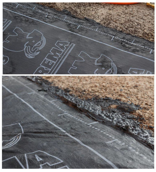
Figure 19.
Quality test at overlaps.
5. Lessons Learned and Suggested Improvements
Although the main objective of the development—installation speed—was achieved, we detected several elements that require improvement. These improvements would lead to faster installation speeds and/or lower consumption. Next, we itemized all weak points and provided suggestion for their improvement:
- The differences in temperature between the adjacent areas show that heat was not entirely uniformly distributed, as the spaces between torches affects the heat distribution. This is something that could be improved by adding more torches or using wider diffusors on each torch;
- As the roll gets installed and unrolled, the distance between the torches and the roll increases, negatively affecting the amount of heat transferred A simple cam-follower mechanism could be integrated between the torches and the roll in order to maintain the distance;
- Heat is lost through the lateral sides of the trolley. A special metallic lateral wall could prevent this loss in the same way that the thermal insulation cover prevents vertical heat losses;
- The lateral stops for the roll are very close to the ground level, and may collide with imperfectly flat areas of ground or surfaces. By elevating the lateral stops by 30–40 mm, these collisions could be avoided;
- If the roll is not perfectly aligned in the lateral sides it is hard to place, since the lateral margins are very small. The lateral stops should have a spring follower mechanism to allow the roll to be positioned in an easier way;
- The hot air flow becomes turbulent around the roll. Future CFD analysis should consider this;
- It is sometimes hard to slightly change the roll direction. By enabling the rotation of the rear wheels, the guidance of the trolley could be easier;
- Increasing the flow in the lateral torches and reducing it in the middle may reduce total consumption;
- Adding extra compaction drums all along the trolley will surely improve the adhesion in the middle without affecting the driving of the trolley;
- We detected slight differences in the flow, and thus on the applied heat, of the torch that was closer to the main pipeline in relation to the one at the other side. This may be due to differences in pressure decay along the pipeline. This difference could be avoided by adjusting the lateral torches and/or by connecting the main pipeline at the middle rather than at one side.
6. Conclusions
In this work, we have described the design and testing of a new piece of equipment, which was developed to enhance speed, gas consumption and safety during the manual asphalt roofing process. The novelty of the equipment is sustained by the use of a set of five parallel gas burners located in front of the roll to maximize the heat transfer. The equipment is light and practical for use by any worker on any type of roof. It also includes a thermal insulation cover to significantly reduce the gas consumption and, thus, to reduce CO2, SO2, and other non-eco-friendly emissions. We have shown the mechanical and thermal design and analysis of the equipment, CFD simulations for the heat transfer calculations, a description of the manufacturing and assembly, a preliminary thermal test, and an operational test.
The equipment demonstrates an installation speed of 1.75 m2/min for 3 kg/m2 rolls, which leads to around 700–735 m2 per person per day, more than twice the usual manual roofing rate. Nevertheless, some issues need to be resolved, such as the nonuniform heat distribution or the low heat transfer at the end of the roll installation. Finally, a complete list of weak points and suggestions for improvement was given.
Author Contributions
Conceptualization, E.D.-J. and A.B.-G.; methodology, E.D.-J. and A.B.-G.; mechanical design, A.B.-G. and M.F.-M.; manufacturing and assembly, A.B.-G. and E.D.-J.; simulation, A.B.-G.; validation test, A.B.-G., E.D.-J., and M.F.-M.; formal analysis, A.B.-G.; literature review, E.D.-J.; data curation, E.D.-J. and A.B.-G.; writing—original draft, A.B.-G. and E.D.-J.; writing—review and editing, E.D.-J. and M.F.-M.; supervision, E.D.-J.; project administration, E.D.-J.; funding acquisition, E.D.-J. and A.B.-G. All authors have read and agreed to the published version of the manuscript.
Funding
The research leading to these results was partially funded by Ingeniería Industrial Ibérica S.A. and Cubiertas ALMADI 2017 S.L.
Acknowledgments
The authors wish to recognize the work of Alba Martínez Pérez during preparation of the figures and 3D pictures.
Conflicts of Interest
The authors declare no conflict of interest.
References
- Abuseif, M.; Gou, Z. A review of roofing methods: Construction features, heat reduction, payback period and climatic responsiveness. Energies 2018, 11, 3196. [Google Scholar] [CrossRef]
- Van Toor, A.C.; Bax, N.X.C. Method and Apparatus for Applying a Bituminous Sheet to a Substrate. Patent EP 0466249, 15 January 1993. [Google Scholar]
- Warren, A. Single Ply Roofing Applicator. U.S. Patent 4725328, 16 February 1988. [Google Scholar]
- Bessette, R. Membrane Applying Apparatus. U.S. Patent 2013228287, 5 September 2013. [Google Scholar]
- Unify-er-Produits. Available online: www.modbitapplicator.com/produits.php (accessed on 4 November 2019).
- Trumbore, D.; Jankousky, A.; Hockman, E.L.; Sanders, R.; Calkin, J.; Szczepanik, S.; Owens, R. Emission factors for asphalt-related emissions in roofing manufacturing. Environ. Prog. 2005, 24, 268–278. [Google Scholar] [CrossRef]
- Vaz, W.; Sheffield, J. Preliminary assessment of greenhouse gas emissions for atactic polypropylene (APP) modified asphalt membrane roofs. Build. Environ. 2014, 78, 95–102. [Google Scholar] [CrossRef]
- EL-Mesery, H.S.; Abomohra, A.E.-F.; Kang, C.-U.; Cheon, J.-K.; Basak, B.; Jeon, B.-H. Evaluation of Infrared Radiation Combined with Hot Air Convection for Energy-Efficient Drying of Biomass. Energies 2019, 12, 2818. [Google Scholar] [CrossRef]
- Young-Corbett, D.E. Prevention through Design: Health Hazards in Asphalt Roofing. J. Constr. Eng. Manag. 2014, 140, 06014007. [Google Scholar] [CrossRef]
- Díez-Jiménez, E.; Vidal-Sánchez, A.; Barragán-García, A.; Fernández-Muñoz, M.; Mallol-Poyato, R. Lightweight equipment for the fast installation of asphalt roofing based on infrared heaters. Energies 2019, 12, 4253. [Google Scholar] [CrossRef]
- Díez-Jiménez, E.; Vidal-Sánchez, A.; Corral-Abad, E.; Gómez-García, M.J. Mecanismo Ligero para la Puesta Rápida de Láminas Bituminosas en Impermeabilizaciones de Cubiertas Planas. Patent P 201830702, 13 July 2018. [Google Scholar]
- Alade, O.; Al Shehri, D.; Mahmoud, M.; Sasaki, K. Viscosity-temperature-pressure relationship of extra-heavy oil (bitumen): Empirical modelling versus artificial neural network (ANN). Energies 2019, 12, 2390. [Google Scholar] [CrossRef]
- Ministerio de Industria, Gobierno de España. Código Técnico de la Edificación, 1st ed.; Garceta Grupo Editorial: Madrid, Spain, 2009; ISBN 9788493720896. [Google Scholar]
- Haynes, W.M. CRC Handbook of Chemistry and Physics; Apple Academic Press: Palm Bay, FL, USA, 2014; ISBN 9781482208672. [Google Scholar]
- Musavi, Z.; Kusar, H.; Andersson, R.; Engvall, K. Modelling and Optimization of a Small Diesel Burner for Mobile Applications. Energies 2018, 11, 2904. [Google Scholar] [CrossRef]


© 2020 by the authors. Licensee MDPI, Basel, Switzerland. This article is an open access article distributed under the terms and conditions of the Creative Commons Attribution (CC BY) license (http://creativecommons.org/licenses/by/4.0/).