Article

A Multi-Source Harvesting System Applied to Sensor-Based Smart Garments for Monitoring Workers’ Bio-Physical Parameters in Harsh Environments

Department of Innovation Engineering, University of Salento, 73100 Lecce, Italy
*
Author to whom correspondence should be addressed.
Energies 2020, 13(9), 2161; https://doi.org/10.3390/en13092161
Submission received: 24 March 2020 / Revised: 18 April 2020 / Accepted: 23 April 2020 / Published: 1 May 2020
(This article belongs to the Special Issue IoT and Sensor Networks in Industry and Society)

Abstract

:
This paper describes the development and characterization of a smart garment for monitoring the environmental and biophysical parameters of the user wearing it; the wearable application is focused on the control to workers’ conditions in dangerous workplaces in order to prevent or reduce the consequences of accidents. The smart jacket includes flexible solar panels, thermoelectric generators and flexible piezoelectric harvesters to scavenge energy from the human body, thus ensuring the energy autonomy of the employed sensors and electronic boards. The hardware and firmware optimization allowed the correct interfacing of the heart rate and SpO2 sensor, accelerometers, temperature and electrochemical gas sensors with a modified Arduino Pro mini board. The latter stores and processes the sensor data and, in the event of abnormal parameters, sends an alarm to a cloud database, allowing company managers to check them via a web app. The characterization of the harvesting subsection has shown that ≈ 265 mW maximum power can be obtained in a real scenario, whereas the power consumption due to the acquisition, processing and BLE data transmission functions determined that a 10 mAh/day charge is required to ensure the device’s proper operation. By charging a 380 mAh Lipo battery in a few hours by means of the harvesting system, an energy autonomy of 23 days was obtained, in the absence of any further energy contribution.

Graphical Abstract

1. Introduction

Wearable devices are electronic systems, operating on the human body, kept continuously switched on to interact with the user or other devices. Nowadays, such devices are pervasive in several aspects of our lifestyle, enabling extensive and real-time monitoring of the wearer’s psycho-physical state. Thus, several devices, including wireless communication modules, sensors, and computational units, have been developed and included inside a t-shirt [1] or connected to a belt [2] or integrated inside shoes [3]. Thanks to the recent scientific and technological advances in the biotechnology and bioengineering fields, considering the high computational capability of new processors with high level of integration and taking into account the availability of accurate, reliable and less invasive integrated sensors, the most recently manufactured wearable devices are smart, small and maintenance-free [4,5,6,7,8]. The main issue that limits the further development and use of wearable devices is the need for recharging and/or replacing the power supply source, usually represented by an energy storage device. If such technical obstacles were overcome, this would allow the manufacturing of energetically autonomous smart and miniaturized devices, thereby enabling easier integration of complex electronic systems into everyday objects. In the near future, this expected development will open the way to the so-called Internet of Everything (IoE), with billions of connected smart devices [9,10,11].
The design of wearable devices imposes several constraints to allow a perfect fit for the human body, to not hinder movements or to weigh down the user. Therefore, the dimensions, weight, flexibility, and comfort have to be taken into account for devising a smart wearable device design [12,13]. These constraints impose limits on the dimensions and capacity of the storage device used to supply power to the device. Moreover, current technologies don’t permit the manufacture of batteries with high energy density, also by using new high-performance materials [14]. Recently, a smart approach for solving the aforementioned issues consists in the integration of energy harvesting systems into the wearable devices [15,16,17]. Harvesting the energy needed to feed the electronic device from the surrounding environment represents the most ecological and sustainable method. Specifically, wearable applications need harvesting systems able to scavenge energy from the sources typical of the human body, e.g., thermal energy, mechanical energy, luminous energy, etc... For these reasons, nowadays, the harvesting technologies are crucial to supply power for low power devices, thus making them energetically autonomous, ensuring a limitless operating time and eliminating service losses [18,19,20]. Different scientific works show how energy scavenging from environmental sources can integrate or totally eliminate the need for an external power supply, thanks to the continuous recharging of the employed storage device [21,22,23,24]. Generally, the approach to energy scavenging from environmental or artificial sources is a function of the typology and availability of energy sources. In fact, based on the power (AC or DC) supplied by source, on its amount and availability of multiple sources, different architectures have to be implemented. However, in its simplest form, the energy harvesting system basically requires an energy source (heat, luminous energy, mechanical energy) and the following key components:
  • a harvester, that transduces the energy supplied by the source into electric energy; typical harvesters are the photovoltaic cells, thermoelectric generators (TEGs), antennas for the radio-frequency (RF) energy, the piezoelectric, electromagnetic, magneto-electric, electrostatic, or triboelectric transducers for mechanical energy (Figure 1);
  • a conditioning electronic unit, that converts the variable signal produced by the harvester into a DC voltage for the electric load; the conditioning section includes a voltage regulator and complex control circuit able to manage the generated power as a function of the power load requirements and available power from the harvester (Figure 1). Also, this section has an impedance matching function for ensuring the maximum transfer of the harvested power;
  • the energy storage device, a battery or super-capacitor (SC); it stores energy gathered by the harvesting unit in order to feed the electronic load in any operating condition (Figure 1).
As regards wearable applications, the most common sources used for energy harvesting are the thermal gradient between the skin and environment, the luminous energy, mechanical energy related to walking, joint (i.e., knees and elbows) movements or arms and legs movements, that are repeated with a frequency of nearly 0.5–3Hz during the walking, thus providing continuous energetic input. Among the aforementioned energy sources, the thermal and luminous energies are the most used, followed by the mechanical one, due to the continuous availability, whereas RF sources are less frequently used, given the reduced amount of energy recoverable by such systems. Table 1 shows a comparison between the power densities related to the different energy sources both in indoor and outdoor environments [25]. A clever strategy for wearable applications consists of the combination of energy contributions provided by different transducers. This multi-source harvesting system ensures energy generations continuously, properly accumulated in a storage device able to power supply the electronic sections. This approach requires solutions for combining the contributions gathered from the different energy sources or simply selecting the source that instantly provides more energy [26,27,28].
The manuscript is structured as follows: the state of art of wearable technologies for energy harvesting and health monitoring is reported in sub-Section 1.1 whereas 1.2 describes the structure and functionalities of the developed energetically autonomous garment, highlighting its possible application scenarios. The second section describes the electronic devices included in both sensing and energy harvesting sub-systems, whereas the third one summarizes the results related to the characterization of each employed harvesting technology (i.e., solar, thermal, piezoelectric), and of the whole harvesting system in different operative scenarios; firmware development to interface sensors equipping the garment with Arduino Pro mini board is also described. In Section 3 the obtained experimental results are reported, whereas they are discussed in the following Section 4.

1.1. Analysis of Wearable Technologies for Energy Harvesting and Health Monitoring

The advances in sensing devices, ultra-low power microcontrollers, storage devices, and low power communication systems have led to a rapid evolution of wearable systems during the last decade [29,30]. Recent wearable applications have involved systems for managing business activities [31] as well as for preventing accidents and protecting workers’ safety and security [32], and mainly in health monitoring, medical or fitness applications [33,34]. In this last context, the main users that could benefit from quasi-real-time monitoring of the health status are the elderly and children, but also users that wish to track their fitness performance. For instance, Carrè Technologies (Montreal, Quebec, Canada) developed a smart shirt for the Canadian space program, able to monitor and record the bio-physical parameters (heart rate, blood pressure and oxygenation, breath rate and body temperature); the acquired data are elaborated and transmitted to a smart device for detecting the onset of cardiovascular or respiratory diseases, as well as continuously monitoring the health status [35]. In [36], the authors reported a device including existing modules for monitoring user bio-physical parameters and warning the rescue unit in case of emergency by means of a communication module, able to also provide direct feedback to a medical center; in addition, the device can assist the patient in the prescribed medical treatment throughout the whole day. Similarly, Al-khafajiy et al. proposed a smart healthcare system able to monitor the health status of elderly people remotely [37]. The proposed system can track the user’s bio-physical parameters for detecting the onset of a disease allowing prevention or rapid intervention in case of illness. The architecture is arranged in three related layers: the Patient layer, represented by the wearable device and smartphone sensors; the Data layer constituted by a cloud data center where the acquired data are stored; the Hospital layer, namely a doctors’ platform synchronized in real-time, which monitors the data to efficiently coordinate a rescue team in the case of an emergency. Nakamura et al. have developed a belt-type wearable device (named WaistonBelt X) equipped with sensors and actuators; a magnetometer monitors the user’s movements and body condition along with accelerometers and a gyroscope in order to recognize the wearer’s lifestyle habits [38]. Statistical data from 17 types of signal (in the time and frequency domains) are calculated using a time window of 1.28 s; the information on the posture is obtained from the belt’s angle by means of accelerometer data. If a bad posture is detected, a vibrator along with a message on a developed application warns the user to correct his position. In [39], the authors have developed two classification methods (named CM-I and CM-II) for detecting fall incidents in elderly users by using wearable altimeter sensors and a probability density function for both falls ( N ( μ F , σ F ) ) and lean over ( N ( μ B , σ B ) ) movements. The methods use the fall time and height data for classifying an incident as fall or lean over; the CM-II method was the best performing option, with a 98% detection capability.
As aforementioned, wearable devices are employed to assess user performances in the sport activity. For instance, Stetter et al. developed a method to measure the knee joint forces (KJF) during common movements, by using two inertial measurement units (IMUs), placed on the leg, and an artificial neural network (ANN) [40]. The IMU signals’ matrix represents the input of a two-layer ANN as well as the KJF matrix is the ANN output; after initial training, the ANN-predicted results were compared with dynamic-calculated forces for several movements performed by 12 participants. The experimental results have shown that ANN-predicted KJFs have a good correlation for all tested movements. Besides, in [41], the authors presented a wearable inertial and magnetic platform enabling an end-to-end analysis of biomechanical parameters, usable for studying significant movement performance during sports activities. This platform consists of five IMU nodes placed in different points of the human body (the wrist, upper arm, forearm, chest, and the waist). These sensors were employed to collect data on the different body sections and thus to extract the motion patterns, which can be linked to injury risk. The timing sequence of the body intersegments can be extracted from the signals provided by the IMUs in a more accurate way than the detection through optical systems; furthermore, positional information can be extracted by employing magnetometer-augmented IMUs to provide information related to the position of the body during the analyzed athletic gesture.
A further application field of wearable devices is environmental monitoring aimed at the measurement of the spatiotemporal distribution of pollutants in the space strictly around the user, enabling one to detect parameters related to the environment healthiness and to correlate eventual diseases to the presence of a particular pollutant [42,43]. For instance, in [44], the authors presented the prototype of a smart t-shirt able to sense the air quality of the surrounding environment; the garment was an Arduino-based system including a TG2620 volatile organic compound (VOC) gas sensor (manufactured by Figaro, Arlington Heights, IL, USA), which provides a synthetic measure of the air quality. Furthermore, Spirjakin et al. developed a sensor-based wearable device for monitoring the working condition able to detect gas leakage [45]. The device is based on an ATxmega165E microcontroller and includes sensors for detecting the air temperature and combustible gases’ concentration by using a catalytic gas sensor (manufactured by NTC IGD, Lyubertsy, Moscow, Russia). The system uses a measuring circuit based on the multi-stage pulse method for reducing the sensor’s power consumption. The acquired data are transmitted to a base station by Zigbee transceiver module interfaced with the ATmega MCU by universal asynchronous receiver transmission (UART). Furthermore, the device can be switched from the sleep condition to the measurement condition through an RF control signal over a distance of about 3 m.
An important challenge for wearable electronics is that the current batteries cannot provide enough energy for operations requiring a long time, inevitably leading to need to frequently replace of the energy storage device or its frequent recharging. Rechargeable Li-ion and Lipo batteries have been widely employed, thus promoting the development of portable electronics for quite a long time. A recent approach is the integration of energy harvesting systems and storage devices resulting in self-charging power systems (SCPSs) for low-power electronics and sensors. Sustainable energy sources to feed wearable devices depend heavily on their availability; different technologies for scavenging energy sources linked to the human body have been developed, such as piezoelectric (PENGs) and triboelectric nanogenerators (TENGs) for the kinetic energy related to movements/vibrations, photovoltaic panels for light energy, thermo-electric generators (TEGs) for thermal energy [46,47,48], etc.
The solar cells can be easily integrated with energy storage devices for providing energy to wearable systems [46]. Recent innovations have made available flexible solar cells with small dimensions, thus suitable for wearable applications; since inorganic materials (e.g., silicon cells) are not suitable, the main alternative is to use solar fiber (FSS) cells employing organic or hybrid materials. [49].
Organic solar cells (OSCs) featurey low weight, intrinsic flexibility of active layers, and low cost, making them most suitable to be fabricated in the form of flexible devices [50]. The OSCs’ power conversion efficiency (PCE) was enhanced rapidly by the creation of new photovoltaic materials with conversion efficiencies higher than 13% [51]. Flexible semi-transparent OSCs have attracted a huge focus in the last few years, enabling new applications such as wearable energy harvesters and solar panels integrated into buildings. The crucial component for high-performance OSCs is cheap and mass-producible flexible bottom transparent electrodes (BTEs); these should have low sheet resistance, high transparency and durability, avoiding cracks and resistance increase with transducer bending [52]. Nowadays, perovskite solar cells (PSCs) are attracting huge interest due to their high conversion efficiency (i.e., ≈ 22%) and simple realization [49,53,54]. In [49], fiber-shaped PSCs are proposed with a flexible cathode realized by metallic twisted wires (i.e., stainless steel or titanium). Also, a thick layer and a porous one in titanium dioxide (TiO2) act as hole blocking layer (HBL) and electron transport layer (ETL), respectively; then a perovskite layer is deposited on the wires. Afterward, a hole transport layer (HTL) made of 2,2′,7,7′-tetrakis(N,N-di-para-methoxy-phenylamine)-9,9-spirobifluorene (spiro-OMeTAD) is deposited; finally, an anode realized by a transparent conductive material, such as carbon nanotubes (CNTs) or a thin layer of gold, is deposited. The perovskite layer absorbs the incident light and the photogenerated electron-hole pairs are separated into the HTL and ETL resulting in a photovoltaic current. Such flexible PSCs can reach a PCE value of 3.3% also after 50 bending cycles. A further approach to increase PCE is the cathodic deposition technique [55], to obtain a uniform perovskite layer on curved supports. These PSCs include an ETL constituted by an array of Ti wires covered by a TiO2 layer, radially grown by an anodization process, which acts as a mesoporous layer for electron extraction and transport. Afterward, a porous lead oxide (PbO) layer is deposited on TiO2 nanorods by getting a lead iodide layer upon reaction with hydroiodic acid; then, the perovskite film is grown treating PbO layer with methylammonium iodide (CH3NH3I). The anode is constituted by a CNT thin film with high transmittance in the visible spectrum (more than 80%) realized by spin-coating an array of aligned CNTs mixed with isopropanol. The PSCs feature a 0.85 V open-circuit voltage (VOC) and a 7.1% conversion efficiency, making them suitable for wearable applications, since they need to be close-fitting and conformable on the body.
A wearable sensor node that integrates a solar energy harvesting circuit and a Bluetooth Low Energy (BLE) transmission module is presented in [56], thus allowing the implementation of a self-powered wireless body area network (WBAN). Several nodes are distributed over different body areas to measure the vital parameters of the user wearing it, such as the temperature, heart rate, and also any falls suffered by user during the day. A web-based application allows the visualization of the acquired data by a smartphone. The energy harvesting system includes a flexible solar cell and the conditioning section with a buck converter and MPPT controller, so that sensor node can operate continuously and non-invasively, without requiring periodic battery recharging.
Mechanical energy related to body movements is an important source that can be exploited for feeding wearable devices. Several harvesters such as piezoelectric, triboelectric and electromagnetic generators have been developed to convert mechanical energy generated by different sources into electrical energy. The piezoelectric transducers represent an efficient solution to convert mechanical solicitations (walk, arms and legs movements, bending of elbows and knees’ joints) into electrical energy. A further advance in this field is the development of piezoelectric nanogenerators (PENGs), realized by using aligned ZnO nanowires (NWs) encapsulated by a dielectric polymer film [46,57], able to harvest energy from tiny, random mechanical forces over a wide frequency range. Several energetically autonomous wearable applications were reported in literature employing piezoelectric harvesters to power supply sensing platforms for monitoring user health conditions [58,59,60]. Yang et al. studied the integration of flexible polyvinylidene fluoride (PVDF) transducers in clothes applied on different human body areas [61]. They evaluated the length variation of piezoelectric transducers and voltage values produced for specific movements (extension or compression of body joints, walking, push-up and torso flexion); higher voltages were obtained with the transducer placed at the elbow level during push-ups. During the walking with the harvester placed on the knee, a 3.1 V voltage was obtained whereas a maximum voltage of 4.4 V with 0.2 mW delivered power was reached during a squat with the harvester placed on the knee. Finally, the harvesting system was able to produce up to 1.42 mW, operating at a frequency of 1Hz and with a 3 MΩ load resistance.
In the last decade, triboelectric generators (TENGs) are gaining huge attention given their high conversion efficiency and constructive simplicity. The TENGs, based on the combination of contact electrification and electrostatic induction, represent a recent technology for energy harvesting and movement sensing. Different operating modes for TENGs have been developed depending on system implementation, excitation type and required outputs [62]. Thanks to their good performances, the TENGs have been used to scavenge energy from biomechanical activities, wind, water motions [63] and vibrations [64]. Different sensors based on TENGs, able to monitor force and pressure, motion, trajectory and biomechanical parameters, have also been proposed [65,66]. One of the most innovative applications involving TENGs is the self-powered electronic skin (or e-skin); try to mimic the sensory capabilities of the human skin by flexible electronic devices is turning out one of the most attractive research fields due to its wide promising applications such as wearable electronics, artificial intelligence and health monitoring [67]. To achieve this goal, it would be necessary to place on the body an enormous sensor network (BSN), but it would be hard to ensure concurrently the power supply. Despite this, the fast growth of innovative materials and micro/nano-manufacturing techniques makes the e-skin feasible by harvesting the mechanical energy related to the human movements. The e-skin can be applied everywhere on the body and employed in several applications, like wearable electronics [68], personal health monitoring, artificial prosthetics [69] and smart robots [70]. The electrodes and dielectric are essential components for building TENGs. The development of new flexible and extendible electrodes and dielectric structures are current issues [71,72]. The e-skin design requires bio-compatible and eco-friendly material, for these reasons organic materials were investigated. For instance, a silk fibroin was tested as TENG’s dielectric, given its strong tendency to yield electrons and eco-compatibility [73]. Since TENG-based sensors are vulnerable to moisture, a chitosan-glycerol film was suggested to prevent the variation of the performance caused by moisture [73].
An energy harvesting method, that is receiving great attention for wearable applications, is the conversion of human biofluids, like sweat, into electrical energy [74,75]. Since many wearable devices operate on the human skin, epidermal biofuel cells (BFCs) have attracted great interest [76]. Sweat-based enzymatic BFCs represent a non-invasive harvesting solution [74], but they can provide power only if the user sweats, and because of the not-constant levels of both sweat and lactate biofuel, such harvesters can’t provide steady output power. Given the low output voltage, the BFCs need an integrated conditioning unit (e.g., DC/DC converter) which could compromise the device flexibility [74]. The sweat-based BFCs harvest energy, through redox chemical reactions, from the lactate fuel contained in the sweat, and are constituted by a bio-anode and a cathode. The bio-anode is functionalized with the enzyme lactate oxidase (LOx) and a naphthoquinone (NQ) redox mediator, for catalyzing the oxidation of lactate and improving the power density, respectively. The active cathode is enriched with silver oxide thus, in the presence of sweat, the biofuel is enzymatically oxidized on the anode, producing an electrons flow toward the cathode (i.e., electrical power) [74]. Besides, in [76] a scalable low-cost screen-printing technology was employed to realize a textile-based BFC harvester by using engineered inks and electrodes with serpentine-shape. The experimental results suggest that at least 40 μL/cm2 of sweat is needed to provide a stable output. An on-body test demonstrated the device operation in real conditions: after 37 min of sweating, the voltage on the storage SC was 0.4 V, suggesting that the harvesting solution doesn’t provide enough power to feed an electronic section, but it represents a future promise. The experiments show that BFCs have good power density (252 μW/cm2), durability, long-term stability, a wide operative range in terms of lactate concentrations, allowing to provide stable outputs for long charging times.
Thermal energy is widely exploited for energy harvesting in wearable applications since the human body heat causes a temperature difference between the skin and surrounding environment [59]. TEGs, based on the Seebeck effect, produce a difference of potential (ΔV) proportional to the temperature gradient on the two junctions (named hot and cold); namely Δ V = S Δ T , where S is the Seebeck coefficient and Δ T the temperature gradient. The Seebeck coefficient varies with the temperature in conductors and depends on the used materials; for common materials (as Bi2Te3 and Sb2Te3), typical S values are between −100 μV/K and +1000 μV/K, while superconductors have a Seebeck coefficient equal to zero [77]. The TEG structure includes several p-n couples connected electrically in series and thermally in parallel, enclosed by two ceramic faces. Good thermoelectric materials have high electrical conductivity (σ) and very low thermal conductivity (κ); this property avoids the heat diffusion from a face to the other, which decreases the temperature gradient and so the generated voltage. The main disadvantage of TEGs is the low conversion efficiency: a module can convert about 7% of the available thermal power into electric power; this is due heat diffusion between the junctions, thus reducing the temperature gradient, and to the thermal resistance of human skin, much higher than TEG ones, so that heat hardly spreads on TEG hot side leading to a Δ T decrease.
In recent years, many advances have been done in the development of micro-TEGs (μ-TEGs), that can produce high output voltages with a very small volume. The working principle of μ-TEGs is the same as TEGs, but they present different structures or have differences in heat flow or electric behavior [78]. The μ-TEGs can be classified according to their structure (vertical, lateral or hybrid), materials and fabrication processes. The vertical structure, known as sandwich, is the conventional one of μ-TEGs (and TEGs). Generally, a μ-TEG has a simple design, high power density and PCE; nevertheless, the main issues of vertical-structured μ-TEGs are the manufacturing difficulties and high technological requirements. The lateral-structured µ-TEGs have easier manufacturing, thanks to their compatibility with IC planar technology [78], but they have lower performances compared to the vertical ones due to the high heat flux leakages towards the substrate and to package design given that the device operates with an in-plane temperature gradient. For these reasons, the lateral structure is commonly employed for sensor applications (e.g., flow, IR and power sensors) and rarely for energy harvesting. Also, µ-TEGs with hybrid structures (i.e., lateral/lateral, vertical/lateral and vertical/vertical) are possible with intermediate performances compared to the previous ones [79]; in a vertical-lateral hybrid structure, the heat flux flows vertically into one edge and passing planarly in the structure, is then emitted in the vertical direction from the other edge. Thereby, this structure exploits the vertical injection/ejection of heat flux for easier packaging as a vertical µ-TEG, keeping the compatibility of the manufacturing process with IC technologies as a laterally structured µ-TEG.
Different energetically autonomous wearable systems, power supplied by TEG harvesters, have been reported in the literature [80]. A BSN for health monitoring applications was proposed in [81], including a sensing section able to acquire, elaborate and wirelessly transmit the data concerning the electrocardiogram (ECG), electromyogram (EMG) and electroencephalogram (EEG). The device is fully fed by the body thermal energy harvested with a TEG and stored into a SC. A digital power management (DPM) system controls the nodes, manages the data flux and the elaborations; also, a low power RF transmitting section periodically transmits the elaborated data toward a gateway.

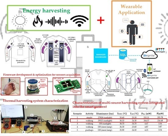
1.2. Description of the Proposed Energetically-Autonomous Wearable Device for Health and Environmental Monitoring Applications in the Workplace.

The problem of safety in the workplace is a has become a deeply felt issue in recent years. In civil society a deep awareness has spread as a consequence of several and recent events such as trauma associated to falls or bruises or intoxications due to leaks of dangerous gases, occurring in the workplace. Therefore, several solutions have been developed for preventing this kind of problem in order to preserve workers’ health and safety. IoT technologies enable low-cost, efficient and not-invasive solutions for monitoring biophysical and environmental parameters directly on the user’s body. The proposed solution is a garment for the upper body, like a jacket, that integrates several sensors to detect both environmental and biophysical quantities which can indicate a dangerous situation for user safety. Its main application is to monitor the conditions of workers operating into particularly dangerous workplaces for human safety, so obtaining detailed and real-time information. Particularly, the device is equipped with a low-power electrochemical carbon monoxide (CO) sensor (model ME2-CO, manufactured by Winsen Inc., Zhengzhou, China) for detecting the CO concentration in the environment around the human body, for instance due to gas leakages or abnormal emissions, an insidious danger since CO is odorless, colorless and particularly poisonous (Figure 2). The CO is produced in combustion phenomenon in conditions of oxygen deficiency, as occurs in stoves, boilers and furnaces. It can be found in numerous industrial areas since its use or emission is linked to several productive activities (e.g., food, chemical, metallurgical industries, etc). The smart garment includes a sulfur dioxide (SO2) sensor (model 3SP_SO2_20, manufactured by Spec Inc, Newark, CA, USA) for obtaining an accurate and punctual detection of SO2 concentration in dangerous workplaces (i.e., tanks for the food transport or in cramped environments), so avoiding accidents sometimes deadly. Given its anti-microbial properties, SO2 is widely used in food industries (e.g., for sugar bleaching and conservation of wine and meat), but it can compromise (also at ppb levels) the respiratory function, leading to pharyngitis, fatigue and sensory disturbances (nose, eyes).
Furthermore, the sensing unit of the designed smart garment includes several sensors for monitoring the worker’s biophysical conditions: a heart-rate, body temperature and SpO2 (concentration of oxygenated hemoglobin) sensor (model MAX30102, manufactured by Maxim Integrated, San Jose, CA, USA) in optical technology (Photo-PlethysmoGram — PPG), placed at the jacket wrist, an integrated accelerometer (model MMA8452Q, manufactured by NXP Semiconductor, Eindhoven, The Netherlands), in correspondence of the user’s waist for monitoring the physical activity level (PAL), the carried out steps number and eventual falls, and a temperature sensor (model LM75A, also manufactured by NXP Semiconductor) for detecting the environmental temperature. Given the application, the sensors were selected as a trade-off of power consumption, measurement accuracy, robustness and cost. The main board used to acquire and elaborate the data from the sensors, to coordinate the transmissions with the gateway and to optimize the device power consumption is a modified Arduino Pro mini (Arduino S.r.l, Torino, Italy).
It is worth noting that the proposed wearable device is self-powered since the garment is equipped with several harvesters for scavenging energy from sources related to the human body, as described below. Specifically, the garment includes two thin-film flexible photovoltaic cells placed on the user’s back, which convert into electrical energy the incident luminous energy (solar or artificial), along with six TEGs for scavenging the thermal energy produced by the body, placed at the forearms to obtain a higher thermal gradient [82]. Furthermore, two piezoelectric harvesters are placed at the elbows to harvest the mechanical energy related to the joint movements (i.e., arms, forearms, shoulders). These transducers are constituted by a TPU (thermoplastic polyurethane) flexible support with a corrugated profile (Figure 2), similar to those reported in [61], on which is applied the series of two commercial polyvinylidene fluoride (PVDF) layers, each with 110 μm thickness, and finally the Ag and NiCu metallization on both sides. Specifically, each support featured by overall dimension 160 mm × 20 mm × 7 mm (thickness at the peak of the corrugation) has been realized by means of 3D printing using Flexismart TPU filament (manufactured by FFFworld, Cantabria, Spain), selected for its extreme flexibility (Shore A88) and resilience to bending and stretching. The support’s corrugated profile allows both higher flexibility (in order not to be invasive for the user), to increase the surface on which to apply the piezoelectric layer, and the mechanical stress induced for a given movement, so getting a greater generated electric charge.
As aforementioned, suitable conditioning sections were used to efficiently extract energy from the harvesters. In particular, two LTC3108-based (manufactured by Linear Technology, Norwood, MA, USA) conditioning sections were used to scavenge energy both from solar cells and TEGs. The LTC3108, an integrated step-up converter with selectable DC output voltage, can be configured as a flyback converter through an external step-up transformer. By using a 1:90 step-up SMD transformer, a minimum input of 22 mV can be harvested, as detailed in the next section (Figure 3). The series of two flexible solar cells is connected to the input terminals of the solar conditioning section, as well as, for each arm the series of three TEGs is connected to the input terminals of the thermal conditioning section. The 5V DC output voltage was selected for all conditioning sections based on LTC3108 IC. Furthermore, two conditioning sections based on the LTC3588-2 buck converter (manufactured by Linear Technology) are employed to harvest energy from the two corrugated piezoelectric harvesters. The LTC3588-2, properly designed to harvest energy from alternate sources, includes an internal low-loss rectifying bridge and a programmable DC output voltage, set to 5 V for the two piezoelectric harvesting stages. The energy contributions provided by each conditioning section are combined through diodes (with 0.8 V forward voltage), employed to avoid the reverse current flow and reduce the output voltage to 4.2 V, maximum voltage value of the rechargeable storage device (380 mAh Lipo battery) (Figure 3).
As above described, an ultra-low-power electronic acquisition and elaboration section, based on ATmega328P microcontroller, periodically transmits, through a CC2541 BLE module (manufactured by Texas Instruments, Dallas, TX, USA), the acquired environmental and biophysical data towards a smartphone which acts as an IoT gateway (powered by the IoT-ignite® platform) for the Internet network (Figure 2). The acquired information, but also alarm messages, are periodically shared with a cloud-based Azure SQL database (DB), in which the information of all company employees is stored, along with the worker’s actual GPS coordinates provided by their smartphones. Furthermore, if the wearable garment detects abnormal values of some environmental or biophysical parameters, by a suitable IFTTT applet, the system sends alarm messages, updating the related record in the storage DB, sending an e-mail/SMS to the security officers, with the last available GPS coordinates of the worker. The smart garment also includes signaling devices (LEDs) and a vibrations generator to immediately warn the user when abnormal parameters (e.g., high gas concentrations) are detected.

2. Materials and Methods

In this section, the energy harvesters (solar cells, TEGs, and piezoelectric transducers) and the sensing devices for detecting environmental and biophysical parameters applied to the designed smart garment are described.

Description of Employed Energy Harvesters and Sensors

The developed smart garment includes two commercial flexible solar panels (models 1w-rx and 0.125W 5V-45*25, manufactured by Dongguan City Xinliangguang New Energy Technology Co., Guangdong, China) placed on the back of the jacket (Figure 4). The used thin-film solar panels have a sandwich structure with three different elements, each tuned on distinct wavelength (red, green blue) to efficiently absorb the sunlight, thus improving the conversion efficiency also with low irradiance levels. The flexible cells are protected by ethylene vinyl acetate (EVA) and polyethylene terephthalate (PET) encapsulation layers laminated in order to make them impermeable and protected from the dust and gases. Two different typologies of solar cells, featured by different dimensions, and thus electrical parameters were employed:
  • Size 1: 197 mm × 97 mm × 0.8 mm dimensions, 1 W maximum electrical power, operating current up to 666 mA, 1.5 V operating voltage, 800 mA short-circuit current and 2 V open-circuit voltage (Figure 4a,b).
  • Size 2: 190 mm × 130 mm × 0.8 mm dimensions, 1.5 W maximum electrical power, operating current up to 1000 mA, 1.5 V operating voltage, 1200 mA short-circuit current and 2 V open-circuit voltage (Figure 4c).
Furthermore, three different TEG typologies have been tested, namely TEC1-12706 (manufactured by Thermonamic inc., Jiangxi, China), TMG-127-1.4-1.2 (manufactured by Ferrotec Nord Corp., Russia, Moscow), and TES1-03102 MINI (manufactured by Wellen Tech Inc., Shenzhen, China), shown in Figure 5a–c, respectively. The first two models have 40 mm × 40 mm dimensions and 127 p-n junctions, whereas the last one has 15 mm × 15 mm dimensions and 31 p-n junctions. They are commonly used as thermo-electric cooler (TEC) devices, based on the Peltier effect, but they can be also used as TEGs for converting thermal energy into electrical energy; in fact, the manufacturers provide their specifications as TECs and, for this reason, their characterization as TEGs was carried out. The output voltage provided by TEGs is variable over time due to variations of the temperature gradient between the two faces or to self-heating phenomenon (i.e., the diffusion of heat from the skin—hot face—the cold one—air). Also, the thermal resistance of skin is higher than that of TEG, leading to lower temperature gradient; hence, the TEGs require proper conditioning section to adapt the provided voltage values to those required by the electronic device to be powered and by the employed charge storage device.
The electronic sections used to harvest energy from both solar panels and TEGs are based on LTC3108 IC (manufactured by Linear Technology), an integrated conditioning system designed to scavenge energy from low-level DC sources (e.g., TEGs, solar cells) (Figure 6). It is based on a DC/DC step-up converter, able to scavenge energy from sources with a 20 mV minimum input voltage (with a 1:100 step-up transformer placed in input to LTC3108 IC), configuring the board as a flyback converter. Actually, a 1:90 step-up transformer (model LPR6235-752RMLB, manufactured by Coilcraft Inc., Cary, IL, USA) was used so increasing the minimum input voltage just to 22.2 mV. Also, the LTC3108 provides power management functionalities, selectable output voltage (2.35, 3.3, 4.1 and 5 V), whereas the impedance matching depends on the transformer’s turn-ratio and input voltage level.
As previously described, the smart garment is equipped with piezoelectric transducers to harvest energy from the joint movements. They were made with a TPU flexible support with a corrugated profile, realized by means of 3D printing, on which two PVDF layers connected in series have been applied for increasing the open-circuit voltage. A commercial PVDF layer with 110 µm thickness (manufactured by TE Connectivity Ltd., Schaffhausen, Switzerland, Figure 7) was employed, NiCu thin sputtered metallization, so ensuring good conductivity and oxidation resistance. The film was cut into strips with 160 mm × 20 mm dimensions and applied on the support’s corrugated surface with silicone glue, to ensure strength and flexibility. The main specifications of the employed piezoelectric film are the following:
  • Electro-Mechanical Conversion: (direction-1) 23 × 10−12 m/V, 700 × 10−6 N/V, (direction-3) −33 × 10−12 m/V;
  • Mechano-Electrical Conversion: (direction-1) 12 mV per microstrain, 400 mV/µm, 14.4 V/N;
  • Pyro-electrical Conversion: (direction 3) 13 mV/N, 8 V/K (@ 25 °C);
  • Capacitance: 1.36 nF; Dissipation Factor of 0.018 @ 10 kHz; Impedance of 12 KΩ @ 10 kHz;
  • Maximum Operating Voltage: DC) 280 V that yields a 7 µm displacement in the direction-1; AC) 840 V that yields a 21 µm displacement in the direction-1;
  • Maximum applied Force (at the break, direction-1): 6–9Kg (yield voltage output: 830 V–1275 V).
The conditioning section used to scavenge energy from the piezoelectric harvester is based on LTC3588-2 IC (manufactured by Linear Technology, Figure 8a), an integrated solution designed and optimized for alternate sources, e.g the piezoelectric one. The LTC3588-2 relies on a high efficiency step-down (buck) DC/DC converter and includes a low losses full-wave rectifier, allowing the direct interfacing of the piezoelectric harvester with the IC (Figure 8b). Furthermore, an under-voltage lockout (UVLO) mechanism, featured by a wide hysteric window, optimizes the charge transfer from the input capacitor (CSTORAGE) to the storage devices (either a supercapacitor or lithium battery); the LTC3588-2 enters its UVLO modality, with an ultra-low quiescent current (450 nA), when an insufficient amount of charge is available from the energy source.
The smart garment includes a MAX30102 PPG sensor (manufactured by Maxim Integrated), for monitoring the heart rate and SpO2 level, which integrates two LEDs (i.e., a red LED at 660 nm and IR one at 880 nm), two photo-detectors for detecting the reflected light from the skin, optical elements and low-noise electronics to reduce the background signal due to ambient light (Figure 9a). It has a dual power supply, at 1.8 V (VDD) for the electronic section and the other with a maximum value of 5.25 V (VLED +), for the two LEDs. The communication with Arduino Pro mini board uses the I2C serial interface and supports standby mode with low power consumption. The MAX30102 sensor integrates a temperature sensor for measuring body temperature (Figure 9b); it is totally controllable through specific registers and the digital output can be saved in a FIFO register with 32 locations (for recording up to 32 samples), whose length depends on the active LED (data from each LED needs 3 bytes, so, if both LEDs are used, each location will be 6 bytes long). This register allows the sensor to be continuously connected with a processor or an external unit, sharing information through the communication bus. Some circuit changes were performed on the breakout board for reducing its power consumption, as discussed in Section 4. In addition, the surface of the board has been covered with a silicone coating to avoid short-cuts due to the contact of uncovered pins with skin. Since the MAX30102 sensor requires a direct contact with the human skin, it has been integrated into the jacket cuff, applied by an elastic band to guarantee a stable contact with the human body.
The software development has been performed for efficiently acquiring both the heart rate and the SpO2, as described in the following section. Afterward, several test campaigns have been carried out by comparing the data acquired by the sensor with the measurements provided by a commercial pulse oximeter (model PR-10, manufactured by CocoBear, Shenzhen, Guangdong, China).
An LM75A digital temperature sensor (manufactured by NXP Semiconductor) is used to monitor the environmental temperature. It relies on a bandgap sensor and includes an 11-bit sigma-delta AD converter for ensuring 0.125 °C resolution on an operative range from −55 °C to +125 °C; the communication with the microcontroller is supported by I2C serial interface. The LM75A can be configured in two operating modes: (a) normal mode to periodically acquire the environmental temperature and (b) the shutdown mode to minimize the power consumption (3.5 µA absorbed current). The sensor has been sewn on the external surface of the jacket sleeve, in order to be in direct contact with the external environment and to measure the temperature regardless of the body temperature.
A monitoring system based on the use of accelerometers is a valid solution for estimating an individual’s physical activity (e.g., pedometers are used in everyday life and in the workplace for discouraging a sedentary lifestyle). Another application of accelerometers concerns the fall detection using wearable devices, being falls very dangerous especially for elders and even fatal if no immediate help is provided. For these reasons, a pedometer and a fall detector have been implemented in the developed smart garment by using a MMA8452Q IC (manufactured by NXP Semiconductor) accelerometer. It is a low-energy three-axis MEMS (x, y, z) accelerometer with 12-bit resolution, embedded functions, flexible programmable options and two selectable interrupt sources. The default auto-sleep and wake up interrupt functions enable energy saving, avoiding that the main unit continuously processes data. The MMA8452Q sensor has a selectable full-scale value of ±2g/±4g/±8g with the possibility of data filtering by a high pass filter; it can be configured to generate an inertial interrupt signal for waking up from one of the possible sleep configurations, thus allowing the MMA8452Q to monitor events and remain in low-power mode during the inactivity periods.
A proper software development has been performed for implementing the aforementioned functionalities, exploiting the embedded functions provided by the MMA8452Q accelerometer, as described below. Furthermore, several tests have been carried out for validating the proper operation of both the implemented pedometer and fall detector under different operative conditions. The accelerometer has been securely fixed to a large elastic band sewn at the waist of the jacket, in order to keep the sensor in a fixed position respect the human body, thus reducing the detection of false falls induced by the motion of the garment respect to the body (Figure 2).
Electrochemical gas sensors have been employed to monitor the environmental concentration of dangerous gaseous species, given their reduced power consumption and small size. In fact, they are featured by lower operative temperature and power consumption than semiconductor sensors, and present lower cost and size compared to the optical ones. For detecting CO concentration, the ZE07-CO module (manufactured by Winsen Inc., Zhengzhou, China) was employed (Figure 10a); it is constituted by a ME2-CO sensor with a conditioning / acquisition board based on a potentiostatic circuit (Figure 10b).
The two-terminal ME2-CO sensor features high precision, low consumption, wide linearity range, and low cross-sensitivity respect to other gases; it has a working range from 0 to 1000 ppm (2000 ppm limit value), and sensitivity equal to 0.015 ± 0.005 µA/ppm. The conditioning board of ZE07-CO module also includes an acquisition section based on ST32F040F4 (manufactured by STMicroelectronics, Geneva, Switzerland) microcontroller, which acquires and elaborates the analog voltage provided by the conditioning section (Figure 10b), and then transmits the data to a master microcontroller by UART interface. This section was removed from the board and the analog voltage is acquired directly by the 10-bit ADC integrated into the ATmega 328P of Arduino Pro Mini board, in order to reduce the power consumption of the conditioning section.
For detecting the sulfur dioxide (SO2) environmental concentration, an Ultra-Low Power Analog Module for Sulfur Dioxide (ULPSM-SO2) 968-006 sensor module (manufactured by Spec Inc.) has been employed (Figure 11a). The module is constituted by a 3SP_SO2_20 sensor and a conditioning board for converting the current signal provided by the sensor into an analog voltage between 0–3 V (Figure 11b). The 3SP_SO2_20 is a three-terminal electrochemical sensor with a measurement range from 0 to 20 ppm, sensitivity of 25 ± 10 nA/ppm, and power consumption between 10 and 50 µW, as a function of gas concentration. Both modules for gas detection were integrated into the garment by placing the conditioning sections in the jacket lining and letting out only the gas sensors from the jacket’s outer fabric.

3. Results

In this section, the results of characterization and functional tests carried out on both energy harvesting system and sensors are summarized, to evaluate the proper operation and performances.

3.1. Estimation of Solar Cells’ Power Efficiency for Different Light Sources and Luminous Intensities

For the employed flexible solar cells, different behavior was observed when they were exposed to different light source typologies (e.g., sunlight and Ne source). In the following Table 2, the current (IIN) and voltage (VIN) values provided by the series of two Size 2 solar cells to the LTC3108-based conditioning section (Figure 8a), equipped with 1:90 step-up transformer, are reported for the two light sources with different illuminance values (similar results are obtained for the Size 1 cells model). The electrical quantities have been measured by two bench multimeters (model GDM-8351, manufactured by Gwinstek, Taipei, Taiwan), whereas the illuminance values by means of a digital luxmeter (model MT-4617, manufactured by Proskit, Taipei, Taiwan). As it can be noted (red box), for a given illuminance value, the tested solar cells have a better response when exposed to sunlight compared to Ne lamp; it can be explained with the different spectral distribution of the two sources. As evident from Figure 12, the solar spectrum covers uniformly the absorption spectrum of solar cells, whereas the Ne lamp one presents two main peaks, at 545 and 610 nm, resulting in a lower efficiency, as also reported in [83,84]. In fact, the smooth and continuous shape of the solar spectrum maximizes the conversion of light into electricity whereas the Ne lamp light concentrated in a few wavelengths determines a low efficiency due to saturation of photons converted into electric charge.
In the following Figure 13, a histogram is shown with reported the power conversion efficiency (PCE) of the Size 1 solar cell, exposed to sunlight (blue bars) or 2 × 14W T5 Ne lamp (red bars), for irradiance values between 0.22 W/m2 and 33.99 W/m2. The obtained data confirm, as previously discussed, that the PCE is higher when solar panels are exposed to the sunlight respect to Ne lamp, for a given irradiance value.
Furthermore, PCE decreases when the irradiance value is reduced regardless of the light source, due to internal parasitic shunt resistance of the solar cells, which dominates at low luminous intensities with consequent reduction of the open-circuit voltage and fill factor (FF) and thus of the power conversion efficiency [85].

3.2. Characterization of the Developed Piezoelectric Harvesters Applied to the Human Body

The flexible piezoelectric harvesters based on 110 µm PVDF layer, with the structure described in sub-Section 1.2 and overall dimensions of 160 mm × 20 mm × 7 mm (at the peak of the corrugated support), were applied by means of an elastic band inside and outside of the elbow and on the shoulder (as depicted in Figure 2) and characterized by performing common joint movements (e.g., arm bending and lifting). Each movement was repeated at 1 Hz frequency keeping them always the same; the maximum value of open-circuit voltage and relative root mean square (RMS) are reported in Table 3. The measurements were carried out employing a digital oscilloscope (model DSO5072P, manufactured by Hantek, Shandong, China) connected to the harvester terminals. In addition, the maximum power (PMax) provided in output by the LTC3588-2 conditioning board was measured by a 100 kΩ load resistor.

3.3. Characterization of the Selected Thermo-Electric Generators and Relative Conditioning Section.

The characterization of TEG devices has been carried out using the experimental setup shown in Figure 14; the TEG series has been connected to the VIN input of the LTC3108-based conditioning board (device 7 in Figure 14) with the output voltage set to 4.1 V and a 1 F SC (device 8) connected to its VOUT pin; a bench multimeter (Gwinstek GDM 8351) (device 1) interfaced with PC (device 2) was used to measure the output current of the conditioning board, whereas two portable multimeters (Model GBC KDM-360CTF, manufactured by GBC Electronics, Milan, Italy, device 3) have been employed to measure the current (IIN) and voltage (VIN) values provided by TEGs.
An infrared heating plate (model 853, manufactured by Foshan Gordak Electric Co., Guangdong, China, device 5 in Figure 14) has been used to heat the hot junction of TEGs, whereas a heat sink has been placed on the cold junction (device 9) to keep the temperature gradient constant as long as possible; an infrared thermometer (model DEM100, manufactured by Velleman, Gavere, Belgium, device 6 in Figure 14), was used to measure the plate and cold joint temperatures at the beginning and end of each test. Each time, TEGs were placed on the hot plate for 10 s, the electrical quantities (VOC, VIN, IIN and IOUT) acquired and then the mean values determined; also, initial and final temperatures of the hot plate and cold joint were measured, calculating their mean values and thus the temperature gradient ∆T.
The following graphs depict the main electrical quantities’ trends, measured for the series of two TEC1-12706 TEGs as function of the temperature gradient; the interpolation lines with relative angular coefficients are also reported (Figure 15). As can be noticed from the previous graphs, they show an almost linear trend, apart from a small deviation in the area around 15 °C–20 °C. Similarly, the electrical quantities have been acquired for two TMG-127-1.4-1.2 TEGs connected in series, by using the same operative modalities above described; the obtained trends are shown in Figure 16.
Afterward, the characterization of the TES1-03102 Mini TEG model has been carried out; this TEG device has a smaller area (15 mm × 15 mm × 3.8 mm) compared to the previous ones and only 31 p-n junctions (Figure 5c). The used experimental procedure for the characterization of two TEGs connected in series is the same used before but the monitoring time interval was increased to 20 s; the following graphs, shown in Figure 17, report the main electrical quantities’ behavior.
From the obtained experimental results, it is possible to draw very different conclusions from those concerning the first TEGs models; relatively to the open-circuit voltages VOC and VIN (Figure 15), the two trends are almost equivalent, since the input voltage values are obtained from related open-circuit voltage ones scaled by a factor of approximately 0.868 (calculated by the ratio of the angular coefficients of the interpolation lines in Figure 17); instead, for the larger models such ratio was equal to about 0.5 (Figure 15). This lower voltage reduction is ascribable to the smaller output impedance of the TES1-03102 Mini TEGs compared to the other tested models with larger area. However, the obtained voltage and current levels are much lower than previously tested models, due to the smaller size and lower number of p-n junctions. Relatively to the TES1-03102 Mini TEGs, considerable difficulties were encountered in carrying out the tests, due to their reduced area, to the uneven distribution of heat on the heating plate and a heterogeneous heat transfer to the TEGs’ hot joint. It was determined that below a ∆T value of 4 °C (Figure 17a–c), the series of two Mini TEGs is unable to provide the minimum input voltage VIN (22 mV) for LTC3108 conditioning module; since typical temperature difference between the skin and environment is in the range 2–8 °C, in the following tests three Mini TEGs connected in series have been employed.
By using the same operative modalities, the series of three TES1-03102 Mini TEGs have been characterized; the following graphs depict the trends of measured electrical quantities as function of ΔT, with also reported he interpolation lines and related angular coefficients (Figure 18).

4. Discussion

From the results reported in Table 2, it can be noted that for a given irradiance level, the conversion efficiency of the tested thin-film solar cells is greater when exposed to solar light compared to an artificial light source (i.e., neon lamp). As afore described, this can be explained by the different spectral power distribution of the two light sources; nevertheless, the efficiency of the solar cells with the artificial neon source wasn’t measured for irradiance values greater than 1.17 W/m2 because of its limited luminous power. As shown in Figure 13, for both light sources, the power conversion efficiency of solar cells decreases greatly for low irradiance values, going from 5.63% to 0.15% with the irradiance changing from 33.99 W/m2 up to only 0.22 W/m2.
Relative to the designed piezoelectric harvesters, from the characterization results reported in Table 3, a higher open-circuit voltage and output power were obtained when they are applied outside the elbow due to the greater induced stress on a larger portion of the harvester. Further optimization of the shape of the flexible support for the piezoelectric layers and a more efficient positioning into the garment will improve their response. In addition, from results reported in paragraph 3.3, by placing three TES1-03102 Mini TEGs in series, the conditioning unit was activated also with low temperature gradient but, with the low current level provided by TEGs (of the order of mA), a long time is required for activating the LTC3108 internal circuitry due to the charge of CAUX capacitor up to the activation voltage (2.5 V).
By comparing the input VIN and open-circuit VOC voltage values for the three Mini TEG series, it can be noted that their ratio (on average equal to 0.71) is lower compared with that obtained for the two TEGs in series (on average equal to 0.87); this is due to the higher impedance of the series of three TEGs with consequent higher internal voltage drop to thermo-electric source. In addition, by comparing the previously characterized TEGs (TMG-127-1.4-1.2 e TEC1-12706) with the TES1-03102 Mini TEGs, it is evident that despite the smaller size of the latter (about 1/7 respect to the larger model), they provide input VIN and open-circuit VOC voltages and input current IIN values obviously lower but the reduction factors are only 1/3 for VOC and 1/2 for VIN; it can be concluded that the Mini TEGs are more performing, with the same ΔT, compared to the other larger TEG model.
Afterward, the energy harvesters and sensors were integrated inside a common jacket using the modality considered most appropriate for ensuring the functionality and efficiency of each device. Specifically, two Size 2 photovoltaic cells connected in series were integrated on the back of the jacket by means of conductive snap buttons, so allowing to easily remove the photovoltaic cells for their replacement or cleaning. The connections with the conditioning section (LTC3108-based board, Figure 6) have been realized by conductive threads (model Electro-Fashion, manufactured by Kitronik Co., Nottingham, UK) soldered to the snap buttons and sewn on the back of the jacket.
The random variations of the incidence angle of the sun’s rays during the body movements cause fluctuations of voltage and current values provided by the solar cells; however, the results obtained from the characterization of smart garment prototype, demonstrate a reduction of the mean power provided by the solar panels of only 20–25% compared to the results reported in sub-Section 3.1, due to the not always optimal orientation during the day of the cells respect to the sun.
Also, two developed piezoelectric transducers, described in the sub-Section 1.2, have been positioned at the elbows of the jacket by pasting them on elastic bands sewn onto the jacket; in this way, the mechanical coupling between the arm and transducer is strongly improved. Similarly, the connections between each harvester and the conditioning section (i.e., LTC3588-2 based board) have been carried out by means of the conductive threads sewn on the sleeve of the jacket. Besides, six TEC1-12706 TEGs were integrated into the smart garment, arranged in two series of three TEGs, each series positioned on the forearm of the jacket and equipped with the LTC3108-based conditioning board; the two TEG-based conditioning sections were connected in parallel through blocking diodes, as already detailed in sub-Section 1.2. Each TEG has been integrated within an elastic band sewn onto the internal surface of the jacket sleeve, in order to keep the hot junction constantly in contact with skin, whereas the cold junction is covered with a perforated fabric; in this way, the airflow on the jacket surface, also due to arm movements, can reduce and keep stable the temperature on the cold junction of TEGs. Because of the absence of a real heatsink and the not perfect contact of the TEGs’ hot side with the skin during the measurement interval, also due to the body movements, a reduction of the provided power ranging between 20% and 30% was observed in the experimental tests of the garment compared to obtained results from the TEGs’ laboratory characterization, reported in the sub-Section 3.3. The conditioning sections have been hidden inside some small pockets realized into the jacket lining, whereas the connections between the transducers and conditioning sections were realized using the conductive threads sewn directly onto the jacket fabric.
As previously described, the MAX30102 heart rate and SpO2 sensor has been placed inside the jacket cuff employing an elastic band in order to keep firmly the sensor on the user’s wrist, thus reducing the measurement errors. Furthermore, the MMA8452Q accelerometer has been embedded into a large elastic band sewn at the waist of the jacket and thus solidly fixed to the monitored body, for reducing errors in the steps counting or fall detection. The LM75A sensor has been sewn by using not conductive threads onto the jacket sleeve, in direct contact with the external environment in order to detect the air temperature.The modules for gas detection (i.e., the ZE8-CO and ULPSM-SO2 968-006) have been positioned inside the jacket lining, placing outside only the gas sensors. The acquisition and elaboration board (Arduino Pro mini) was positioned inside a small pocket on the back of the developed garment, along with the communication section (based on CC2541 IC) and the energy storage device (i.e., a 380 mAh Lipo battery).
Different measurement campaigns were performed to evaluate the performances of the multi-source harvesting system integrated into the smart garment when it is worn by a user, and in different operative scenarios, as following described:
  • Scenario 1: a stationary user with a body temperature of 35.6 °C exposed to direct sunlight;
  • Scenario 2: a user walking quickly (5 km/h) and exposed to direct sunlight with a body temperature of 36.1 °C;
  • Scenario 3: a user walking quickly (5 km/h) and exposed to diffused sunlight with a body temperature of 36.3 °C;
  • Scenario 4: a user walking quickly (5 km/h) and exposed to artificial light (neon lamp) with a body temperature of 36.3 °C;
  • Scenario 5: a user performing pushups (0.5 Hz) and exposed to artificial light (neon lamp) with a body temperature of 35.9 °C.
An electronic load (model Tenma 72-13210, manufactured by Tenma®, Springboro, OH, USA), configured in constant resistance modality (100 kΩ), was connected to the output of the multi-source harvesting system, to monitor the maximum power provided to the load; the results in the different scenarios are summarized in the following Table 4. For each scenario, five different tests were carried out considering an observation interval of 30 min every time, during which the current values absorbed by the electronic load were acquired and recorded by means of a digital multimeter (Model PM8236, manufactured by Peakmeter®, Shenzhen, China), with a sampling time interval of 30 s. From the obtained time-domain trends, the maximum values of power provided by the multi-source harvesting system were obtained. In Table 4, the mean values of maximum power (PMax) over the five tests for each scenario were reported together with the mean temperatures (TAIR and TBODY) and illuminance values. Furthermore, the mean value of the power ( P ¯ ), provided by the harvesting section over the five tests, was reported in Table 4 for each scenario.
The solar harvesting system provides the main contribution to the electrical power stored on the battery when the garment is exposed to sunlight, but it ensures a continuous charging of the 380 mAh Lipo battery also under diffused sunlight (Scenario 3) or artificial light (Scenarios 4–5), thanks to the continuous over-time contributions of the thermal and piezoelectric harvesting sub-sections. In the following section, it is demonstrated that the developed harvesting section, also in the worst case (Scenario 5), is able to guarantee the energy autonomy of the sensing and communication units. Following, additional tests were performed in order to determine the power contribution of each harvesting section, by placing a digital multimeter (Model PM8236) in series to each harvesting section. Specifically, for Scenarios 1 and 2, the contribution of the solar cells represents about 98% of the total power provided by the whole harvesting system, whereas the piezoelectric (0.1–0.2% only for Scenario 2) and thermal (1.5–2%) harvesters give some negligible contributions. Conversely, in the third scenario (Scenario 3), the power contributions of the solar and piezoelectric harvesting sections are much lower (respectively 6–7% and 5–6% of the total provided power) respect to the TEGs power contribution (high up to 87%). In Scenario 4, the contribution of the thermal harvesting section, including six TEC1-12706 TEGs, was equal to 4.46 mW (referred to the maximum provided power PMax), whereas the contributions of the solar and piezoelectric ones were only 0.13 mW and 0.28 mW, respectively. Finally, in the Scenario 5, 3.77 mW was the contribution of the thermal harvesting section (due to a lower temperature gradient—precisely −1.3 °C—with respect to Scenario 4), whereas the photovoltaic and piezoelectric power contributions were only 0.13 mW and 0.35 mW, respectively. In this last case, the piezoelectric harvesters provide a higher power compared to Scenario 4, since push-ups excite more strongly the transducers, as already verified in sub-Section 3.2. These results confirm the afore reported concept, namely that also in the condition of low level of illumination (Scenarios 3, 4 and 5), the thermal harvesting section, based on six TEC1-12706 TEGs, is able to provide a continuous charge flow on the Lipo battery and therefore to power supply the entire designed system.

Testing and Characterization of the Sensors Included in the Smart Garment

In this section, the functional tests and the characterization carried out on the sensors, included in the developed smart garment, are described. A modified Arduino Pro mini, based on ATmega 328P MCU, represents the motherboard of the smart garment; this MCU offers six different sleep modalities to reduce its power consumption up to µA values. In particular, the built-in 3.3 V voltage regulator (78L05 made by STMicroelectronics) featured by 6 mA of maximum quiescent current was replaced with a more efficient one (model XC6206P332MRI, manufactured by Torex Semiconductor, Tokyo, Japan) with lower quiescent current (typical value 1 µA). Also, the MCU clock frequency was reduced from 16 MHz to 8 MHz provided by the internal oscillator, obtaining a drastic reduction of the absorbed current from the Arduino board in power-down mode, up to the value of only 23 µA.
Relative to the MAX30102 sensor, the Arduino code has been developed for performing the fundamental functions of signal processing provided by the two integrated photo-detectors (red and IR) and for interfacing the sensor with the MCU; subsequently, the code has been optimized for obtaining a low level of data memory occupation (an important aspect in this application). Also, the 3.3 V voltage regulator (model 10A45, manufactured by Saiertong, Shenzhen, China) was removed and bypassed, since the sensor is fed by using the 3.3 V Arduino output pin (yellow box in Figure 9c). Figure 19 shows the two anatomical areas (i.e., the wrist and fingertip) with the sensor of Figure 9d properly applied to detect the SpO2 and HR. Relatively to the integration of MAX30102 sensor in the smart garment, it was positioned in correspondence of the wrist into the elastic jacket cuff.
A commercial pulse-oximeter CocoBear (Figure 19c) has been used to measure the HR and SpO2 values and compare them with those provided by the MAX30102 sensor (Table 5); the sensor was positioned as shown in Figure 19a and the values were detected every 30 s, simultaneously from both devices. From data reported in Table 5, after performed optimization of developed code for HR and SpO2 calculation, a good agreement between the values obtained by the MAX30102 sensor and the CocoBear oximeter was obtained, with a maximum difference of 3 BPM for HR and 1% for SpO2 values; moreover, the convergence time for getting correct SpO2 values was less than 5 s. The power consumption of the MAX30102 module has been measured, both in active mode and power save mode, by acting on the shutdown control bit of the internal configuration register; the current absorbed by MAX30102 module was 1.25 mA in active mode and just 1.5 µA in power saving mode.
The developed garment is also equipped with a pedometer and fall detector, both implemented by means of the MMA8452Q 3-axis accelerometer. The firmware for the pedometer allows detecting a step by comparing the total acceleration value (i.e., combined acceleration on the three axes) with an experimentally derived threshold, whereas a hysterical detection mechanism prevents multiple increments for each step. The threshold value affects the algorithm sensitivity and its careful optimization has been carried out, in different test conditions, for avoiding an overestimation (for low threshold values) or underestimation (for high threshold values) of performed steps. The following Table 6 refers to the use of MMA8452Q accelerometer for a walk at normal pace, positioning it on the waist, as shown in Figure 20, to ensure high detection capability [86] and low influence by interpersonal differences in the body movements, since the sensor is not stressed by movements and accelerations, different from those generated by performed steps.
The results reported in Table 6 demonstrate that, by lowering the threshold value, the sensor overestimates the number of performed steps, since even low acceleration values, not related to an actually executed step, are greater than the threshold and counted as a step. Conversely, with high threshold values, the accelerometer underestimates performed steps number, since low accelerations generated by a possible lighter step are not detected; more proper threshold values range from 220 to 230. Besides, to improve the accuracy of the developed pedometer during the run, a software mechanism was implemented for suppressing the signal spikes that could corrupt the steps count.
The MMA8452Q sensor implements a freefall detection algorithm based on the analysis of the acquired acceleration values along the three-axis, (by setting the XEFE, YEFE, ZEFE bits in the FF_MT_CFG register), verifying if they are all lower than a predetermined threshold (as detailed in the datasheet). If this event occurs for a time exceeding a set time duration (debounce time, set to 100 ms), then an interrupt is triggered; otherwise, events with duration lower than the debounce time are ignored. An accelerometer interrupt pin was set as interrupt source for the MCU normal routine; if a fall event occurs, an ISR (interrupt service routine) in the MCU is executed, so generating an alarm signal. The acceleration threshold value, set in the FF_MT_THS register of the MMA8452Q sensor and coded by seven bits (8 g full scale and consequently 0.063 g resolution), is crucial for the afore described mechanism; thus, its optimization has been performed to guarantee a high detection capability of the sensor. The MMA8452Q sensor was positioned on the waist (as shown in Figure 20) since this body area was identified as the most suitable to guarantee excellent fall detection [86]. In Table 7, a comparison between the number of falls performed by the user and falls detected by the sensor is reported, highlighting the false not-occurred falls as a function of the threshold value.
From data reported in Table 7, it is evident that the optimal threshold values for fall detection, regardless of the physical characteristics of the subject wearing the MMA8452Q sensor, are 4 and 5 (0.252 g or 0.315 g). Finally, the threshold value was set to 4, since even the employed commercial fall detector, placed on the user’s waist, tends to underestimate the total number of performed falls.
Some modifications were carried out on the accelerometer breakout board; the 5 V built-in regulator (LG33, Micrel, San Jose, CA, USA) was removed since the sensor was fed directly to 3.3 V provided by the voltage regulator (XC6206P332MRI, Torex Semiconductor) placed on the Arduino Pro mini board. For reducing the power consumption, the built-in auto-wake/auto-sleep functionality was exploited, bringing the sensor in power-down mode if no motion is detected. In power-down mode, the data acquisition rate of the acceleration sensor is significantly lowered (Output Data Rate—ODR—reduced from 800 Hz to 56 Hz), and it is wake up, via an interrupt signal, when an acceleration higher than the set threshold is detected. The measurement of the current absorbed by the modified MMQ8452Q board demonstrates that the accelerometer draws 210 µA during the data acquisition phase and only 6 μA in the power-down modality.
As aforedescribed, the smart garment also includes some electrochemical gas sensors for detecting gaseous species dangerous for human health, for instance, a modified ZE07-CO module (Winsen Inc.) for detecting the CO concentration in the environment around the user. The module includes an acquisition and communication unit based on ST32F040F4 (made by STMicroelectronics) MCU and a potentiostatic conditioning unit based on SGM8042Y28 (made by SGMicro) operational amplifier (Figure 21a). For reducing the power consumption of the ZE07-CO module, the acquisition and communication unit has been removed from the board, along with the 3V voltage regulator LP2980 (made by National Semiconductor) and the onboard DAC (digital to analog) converter (Figure 21b). In this way, the analog signal produced by the conditioning unit was acquired directly by the 10-bit ATmega328P ADC of the Arduino Pro mini board and converted into the gas concentration (expressed in ppm-part per million) through the stage transfer function (1):
g a s   c o n c e n t r a t i o n = V 0.2686   V o l t 0.003   V / p p m
where the gas concentration is expressed in ppm and V , the acquired voltage, is in Volts.
The measurement of the current absorbed by the modified ZE07-CO module demonstrates that a current of just 4.6 µA is required in the low gas concentration condition. By the tests carried out on the harvesting system, about 4 h of initial charging time in Scenario 2 (Table 4) are required to fully charge the 380 mAh Lipo battery. The operative strategy involves the acquisition, elaboration, and transmission of the environmental and biophysical parameters every 15 min, whereas the fall detector acts as an interrupt source for the MCU triggering an ISR, with consequent transmission of a warning message to the cloud app. Furthermore, the performed measurements on the electronic section indicate that the mean absorbed current in power-down mode is 88.74 µA, as well as in active mode just 7.46 mA; since the overall time duration of the measurement, elaboration and transmission phases was equal to 40 s, the charge required for the daily system operation was 9.99 mAh. Therefore, by supposing a 40% discharge margin of the Lipo battery, the autonomy of the smart garment in the total absence of any contribution from the harvesting section is given by (2):
A u t o n o m y = B a t t e r y   C a p a c i t y ( 1 D i s c h a r g e   M a r g i n ) E n e r g y   C o n s u m p t i o n   p e r   d a y = 380   m A h ( 1 0.4 ) 9.99   m A h / d a y = 22.82   d a y
Thanks to the implementation of a proper operative strategy and power consumption minimization of the different sections into the smart garment, exploiting low power operating modes for the MCU and sensors, an autonomy of ≈ 23 days can be ensured in a total absence of the energetic contributions from the different harvesting sections included in the developed system. Finally, downstream of all performed hardware and software optimizations to obtain minimization of power consumption, considering that the sensing and communication units need about 0.42 mAh for every hour of operation (9.99 mAh/24 h), the energy harvesting section is able to provide, also in the worst scenario (Scenario 5 of Table 4), more than twice (0.850 mAh) compared to the needed charge (0.42 mAh), so ensuring the energy autonomy of the designed smart electronic garment.
After the integration of sensors inside the smart garment according to the modalities described in the fourth section, several tests were carried out exploiting the results obtained from the afore reported characterizations. For all sensors integrated into the smart garment, the correct operation was verified by comparing the measurements provided by each sensor with those obtained by external instruments, namely a thermometer, a pulse-oximeter, a step-counter and a gas detector. Only for the MMA8452Q-based steps counter has a slight (+20%) overestimation of the step counting been noticed, probably due to small movements of the elastic band where the accelerometer has been placed, issue solvable with a successive optimization of the acceleration threshold, involved in the step counter firmware, directly on the smart garment.

5. Conclusions

This manuscript aims to describe the development and characterization of a smart garment able to detect the environmental and biophysical parameters of a user wearing it, specially designed to monitor conditions in particularly dangerous workplaces and thus to prevent or reduce the consequences of worker accidents. The developed device is a joint application of low-power electronic sections and energy harvesting solutions, to ensure the energetic autonomy of the system; in fact, the smart garment includes flexible solar panels, TEGs and flexible piezoelectric harvesters to scavenge energy from sources closely related to the human body. The smart jacket shares acquired information and warning signaling with an on-cloud database, enabling company managers to check them through a web application. The results of the characterization of the selected energy harvesters with related conditioning sections have been reported in different real application scenarios. Moreover, the firmware to interface employed sensors (HR-SpO2 sensor, accelerometers, environmental temperature and electrochemical gas sensors) with a modified Arduino Pro mini board has been developed; particular attention was paid to the implementation of hardware and software strategies aimed to reduce the overall energy consumption of the system. Furthermore, the characterization results derived from the experimental tests on different sensors included in the smart garment have been reported, to optimize the characteristic parameters of developed firmware.
The multi-source energy harvesting system integrated inside the smart garment was characterized in order to determine the maximum power provided in different real operative scenarios. The obtained results have demonstrated the predominance of solar contribution in the condition of direct solar illumination (Scenarios 1 and 2 with the user wearing the jacket, outdoors) compared to the thermal and piezoelectric effects; instead, the TEGs-based thermal harvesting section provides a continuous contribution, dominant respect to those others, in conditions of solar diffused or artificial light (Scenarios 3, 4 and 5), however ensuring the energy autonomy of the complete developed system in all the operative conditions. Besides, tests performed on the sensing section integrated inside the proposed wearable application indicated the correct operation of all included sensors, thanks to the parameters optimization previously performed. In addition, the power consumption measurements on acquisition, elaboration and communication subsections demonstrated that about a 10 mAh charge is needed to ensure the daily system functionality; in this way, by using a 380 mAh Lipo battery, as storage device charged by the designed harvesting section, an autonomy of more than 20 days was obtained by exploiting the usable battery charge (60%), if no energy contribution is available over time.

Author Contributions

Relatively to the present manuscript, the authors R.d.F., P.V., G.M. and A.M. carried out the experimental activities, as well as they wrote the manuscript. D.C. supervised the activities and data analysis, as well as he has contributed to the manuscript editing. All authors have read and agreed to the published version of the manuscript.

Funding

This research received no external funding.

Conflicts of Interest

The authors declare no conflict of interest.

References

  1. Mathias, D.N.; Kim, S.-I.; Park, J.; Joung, Y.-H. Real Time ECG Monitoring Through a Wearable Smart T-shirt. Trans. Electr. Electron. Mater. 2015, 16, 16–19. [Google Scholar] [CrossRef] [Green Version]
  2. Kamišalić, A.; Fister, I.; Turkanović, M.; Karakatič, S. Sensors and Functionalities of Non-Invasive Wrist-Wearable Devices: A Review. Sensors 2018, 18, 1714. [Google Scholar] [CrossRef] [PubMed] [Green Version]
  3. Eskofier, B.M.; Lee, S.I.; Baron, M.; Simon, A.L.; Martindale, C.F.; Gassner, H.; Klucken, J. An Overview of Smart Shoes in the Internet of Health Things: Gait and Mobility Assessment in Health Promotion and Disease Monitoring. Appl. Sci. 2017, 7, 986. [Google Scholar] [CrossRef] [Green Version]
  4. Prauzek, M.; Konecny, J.; Borova, M.; Janosova, K.; Hlavica, J.; Musilek, P. Energy Harvesting Sources, Storage Devices and System Topologies for Environmental Wireless Sensor Networks: A Review. Sensors (Basel) 2018, 18, 2446. [Google Scholar] [CrossRef] [Green Version]
  5. Munir, B.; Dyo, V. On the Impact of Mobility on Battery-Less RF Energy Harvesting System Performance. Sensors (Basel) 2018, 18, 3597. [Google Scholar] [CrossRef] [Green Version]
  6. Lee, H.G.; Chang, N. Powering the IoT: Storage-less and converter-less energy harvesting. In Proceedings of the 20th IEEE Asia and South Pacific Design Automation Conference, Chiba, Japan, 19–22 January 2015; pp. 124–129. [Google Scholar]
  7. Tang, X.; Wang, X.; Cattley, R.; Gu, F.; Ball, A.D. Energy Harvesting Technologies for Achieving Self-Powered Wireless Sensor Networks in Machine Condition Monitoring: A Review. Sensors (Basel) 2018, 18, 4113. [Google Scholar] [CrossRef] [Green Version]
  8. Eren, H.; Webster, J.G. Telemedicine and Electronic Medicine; CRC Press: Boca Raton, FL, USA, 2018; ISBN 978-1-351-23147-3. [Google Scholar]
  9. Dimitrov, D.V. Medical Internet of Things and Big Data in Healthcare. Healthc. Inform. Res. 2016, 22, 156–163. [Google Scholar] [CrossRef]
  10. Zeinab, K.A.M.; Elmustafa, S.A.A. Internet of Things Applications, Challenges and Related Future Technologies. World Sci. News 2017, 67, 126–148. [Google Scholar]
  11. Visconti, P.; de Fazio, R.; Primiceri, P.; Cafagna, D.; Strazzella, S.; Giannoccarro, I.N. A Solar-Powered Fertigation System based on Low-Cost Wireless Sensor Network Remotely Controlled by Farmer for Irrigation Cycles and Crops Growth Optimization. Int. J. Electron. Telecommun. 2020, 66, 59–68. [Google Scholar]
  12. Jokic, P.; Magno, M. Powering smart wearable systems with flexible solar energy harvesting. In Proceedings of the 2017 IEEE International Symposium on Circuits and Systems (ISCAS), Baltimore, MD, USA, 28–31 May 2017; pp. 1–4. [Google Scholar]
  13. Haghi, M.; Thurow, K.; Stoll, R. Wearable Devices in Medical Internet of Things: Scientific Research and Commercially Available Devices. Healthc. Inform. Res. 2017, 23, 4–15. [Google Scholar] [CrossRef]
  14. Abraham, K.M. Prospects and Limits of Energy Storage in Batteries. J. Phys. Chem. Lett. 2015, 6, 830–844. [Google Scholar] [CrossRef] [PubMed]
  15. Visconti, P.; Primiceri, P.; Orlando, C. Solar Powered Wireless Monitoring System of Environmental Conditions for Early Flood Prediction or Optimized Irrigation in Agriculture. ARPN J. Eng. Appl. Sci. 2016, 11, 4623–4632. [Google Scholar]
  16. Visconti, P.; Ferri, R.; Pucciarelli, M.; Venere, E. Development and Characterization of a solar-based energy harvesting and power management system for a WSN node applied to optimized goods transport and storage. Int. J. Smart Sens. Intell. Syst. 2016, 9, 1637–1667. [Google Scholar]
  17. Visconti, P.; Primiceri, P.; Ferri, R.; Pucciarelli, M.; Venere, E. An Overview On State-of-Art Energy Harvesting Techniques and Choice Criteria: A WSN Node for Goods Transport and Storage Powered by a Smart Solar- Based EH System. Int. J. Renew. Energy Res. 2017, 7, 1281–1295. [Google Scholar]
  18. Loncar-Turukalo, T.; Zdravevski, E.; da Silva, J.M.; Chouvarda, I.; Trajkovik, V. Literature on Wearable Technology for Connected Health: Scoping Review of Research Trends, Advances, and Barriers. J. Med. Internet Res. 2019, 21, 1–23. [Google Scholar] [CrossRef]
  19. Iqbal, M.H.; Aydin, A.; Brunckhorst, O.; Dasgupta, P.; Ahmed, K. A review of wearable technology in medicine. J. R. Soc. Med. 2016, 109, 372–380. [Google Scholar] [CrossRef]
  20. Al-Eidan, R.M.; Al-Khalifa, H.; Al-Salman, A.M. A Review of Wrist-Worn Wearable: Sensors, Models, and Challenges. J. Sens. 2018, 2018, 1–20. [Google Scholar] [CrossRef] [Green Version]
  21. Ramadass, Y.K.; Chandrakasan, A.P. A Battery-Less Thermoelectric Energy Harvesting Interface Circuit With 35 mV Startup Voltage. IEEE J. Solid-State Circuits 2011, 46, 333–341. [Google Scholar] [CrossRef]
  22. Kim, S.; Vyas, R.; Bito, J.; Niotaki, K.; Collado, A.; Georgiadis, A.; Tentzeris, M.M. Ambient RF Energy-Harvesting Technologies for Self-Sustainable Standalone Wireless Sensor Platforms. Proc. IEEE 2014, 102, 1649–1666. [Google Scholar] [CrossRef]
  23. Thielen, M.; Sigrist, L.; Magno, M.; Hierold, C.; Benini, L. Human body heat for powering wearable devices: From thermal energy to application. Energy Convers. Manag. 2017, 131, 44–54. [Google Scholar] [CrossRef] [Green Version]
  24. de Fazio, R.; Cafagna, D.; Marcuccio, G.; Visconti, P. Limitations and Characterization of Energy Storage Devices for Harvesting Applications. Energies 2020, 13, 783. [Google Scholar] [CrossRef] [Green Version]
  25. Silva, F.A. Handbook of Energy Harvesting Power Supplies and Applications [Book News]. IEEE Ind. Electron. Mag. 2016, 10, 67–68. [Google Scholar] [CrossRef]
  26. Cai, Y.; Deng, F.; Zhao, J.; Qiu, H.; Fan, X.; Liang, Z. The Distributed System of Smart Wearable Energy Harvesting Based on Human Body. In Proceedings of the 2018 IEEE 37th Chinese Control Conference (CCC), Wuhan, China, 25–27 July 2018; pp. 7450–7454. [Google Scholar]
  27. Alhawari, M.; Tekeste, T.; Mohammad, B.; Saleh, H.; Ismail, M. Power management unit for multi-source energy harvesting in wearable electronics. In Proceedings of the 2016 IEEE 59th International Midwest Symposium on Circuits and Systems (MWSCAS), Abu Dhabi, UAE, 16–19 October 2016; pp. 1–4. [Google Scholar]
  28. Kim, S.-E.; Kang, T.; Oh, K.-I.; Park, M.J.; Park, H.-I.; Lim, I.G.; Lee, J.-J. Energy Management Integrated Circuit for Multi-Source Energy Harvesters in WBAN Applications. Appl. Sci. 2018, 8, 1262. [Google Scholar] [CrossRef] [Green Version]
  29. Visconti, P.; de Fazio, R.; Costantini, P.; Miccoli, S.; Cafagna, D. Arduino-Based Solution for In-Car- Abandoned Infants’ Controlling Remotely Managed by Smartphone Application. JCOMSS 2019, 15, 89–100. [Google Scholar] [CrossRef] [Green Version]
  30. Gaetani, F.; Primiceri, P.; Antonio Zappatore, G.; Visconti, P. Hardware design and software development of a motion control and driving system for transradial prosthesis based on a wireless myoelectric armband. IET Sci. Meas. Technol. 2019, 13, 354–362. [Google Scholar] [CrossRef]
  31. Osswald, S.; Weiss, A.; Tscheligi, M. Designing wearable devices for the factory: Rapid contextual experience prototyping. In Proceedings of the 2013 IEEE International Conference on Collaboration Technologies and Systems (CTS), San Diego, CA, USA, 20–24 May 2013; pp. 517–521. [Google Scholar]
  32. Alam, M.M.; Hamida, E.B. Surveying Wearable Human Assistive Technology for Life and Safety Critical Applications: Standards, Challenges and Opportunities. Sensors 2014, 14, 9153–9209. [Google Scholar] [CrossRef] [PubMed] [Green Version]
  33. Takei, K.; Honda, W.; Harada, S.; Arie, T.; Akita, S. Toward Flexible and Wearable Human-Interactive Health-Monitoring Devices. Adv. Healthc. Mater. 2015, 4, 487–500. [Google Scholar] [CrossRef]
  34. Mantua, J.; Gravel, N.; Spencer, R.M.C. Reliability of Sleep Measures from Four Personal Health Monitoring Devices Compared to Research-Based Actigraphy and Polysomnography. Sensors 2016, 16, 646. [Google Scholar] [CrossRef] [Green Version]
  35. Bio-Monitor: Keeping an Eye on Astronauts’ Vital Signs. Available online: https://www.asc-csa.gc.ca/eng/sciences/bio-monitor.asp (accessed on 12 April 2020).
  36. Qaosar, M.; Ahmed, S.; Li, C.; Morimoto, Y. Hybrid Sensing and Wearable Smart Device for Health Monitoring and Medication: Opportunities and Challenges. In Proceedings of the AAAI Spring Symposium Series; Association for the Advancement of Artificial Intelligence, Palo Alto, CA, USA, 26–28 March 2018; Volume 1, pp. 269–274. [Google Scholar]
  37. Al-khafajiy, M.; Baker, T.; Chalmers, C.; Asim, M.; Kolivand, H.; Fahim, M.; Waraich, A. Remote health monitoring of elderly through wearable sensors. Multimed. Tools Appl. 2019, 78, 24681–24706. [Google Scholar] [CrossRef] [Green Version]
  38. Nakamura, Y.; Matsuda, Y.; Arakawa, Y.; Yasumoto, K. WaistonBelt X: A Belt-Type Wearable Device with Sensing and Intervention Toward Health Behavior Change. Sensors 2019, 19, 4600. [Google Scholar] [CrossRef] [Green Version]
  39. Kyriakopoulos, G.; Ntanos, S.; Anagnostopoulos, T.; Tsotsolas, N.; Salmon, I.; Ntalianis, K. Internet of Things (IoT)-Enabled Elderly Fall Verification, Exploiting Temporal Inference Models in Smart Homes. Int. J. Environ. Res. Public Health 2020, 17, 408. [Google Scholar] [CrossRef] [PubMed] [Green Version]
  40. Stetter, B.J.; Ringhof, S.; Krafft, F.C.; Sell, S.; Stein, T. Estimation of Knee Joint Forces in Sport Movements Using Wearable Sensors and Machine Learning. Sensors 2019, 19, 690. [Google Scholar] [CrossRef] [PubMed] [Green Version]
  41. Lapinski, M.; Brum Medeiros, C.; Moxley Scarborough, D.; Berkson, E.; Gill, T.J.; Kepple, T.; Paradiso, J.A. A Wide-Range, Wireless Wearable Inertial Motion Sensing System for Capturing Fast Athletic Biomechanics in Overhead Pitching. Sensors 2019, 19, 3637. [Google Scholar] [CrossRef] [PubMed] [Green Version]
  42. Mamun, M.A.A.; Yuce, M.R. Sensors and Systems for Wearable Environmental Monitoring Toward IoT-Enabled Applications: A Review. IEEE Sens. J. 2019, 19, 7771–7788. [Google Scholar] [CrossRef]
  43. Haghi, M.; Stoll, R.; Thurow, K. A Low-Cost, Standalone, and Multi-Tasking Watch for Personalized Environmental Monitoring. IEEE Trans. Biomed. Circuits Syst. 2018, 12, 1144–1154. [Google Scholar] [CrossRef]
  44. Kim, S.; Paulos, E.; Gross, M.D. WearAir: Expressive t-shirts for air quality sensing. In Proceedings of the TEI ’10, Cambridge, MA, USA, 25–27 January 2010; pp. 295–296. [Google Scholar]
  45. Spirjakin, D.; Baranov, A.; Akbari, S. Wearable Wireless Sensor System With RF Remote Activation for Gas Monitoring Applications. IEEE Sens. J. 2018, 18, 2976–2982. [Google Scholar] [CrossRef]
  46. Pu, X.; Hu, W.; Wang, Z.L. Toward Wearable Self-Charging Power Systems: The Integration of Energy-Harvesting and Storage Devices. Small 2018, 14, 1–20. [Google Scholar] [CrossRef]
  47. Lee, J.-H.; Kim, J.; Kim, T.Y.; Hossain, M.S.A.; Kim, S.-W.; Kim, J.H. All-in-one energy harvesting and storage devices. J. Mater. Chem. A 2016, 4, 7983–7999. [Google Scholar] [CrossRef] [Green Version]
  48. Kim, J.H.; Kim, S.-W.; Wang, Z.L. Preface for Special Topic: Nanogenerators. APL Mater. 2017, 5, 073701. [Google Scholar] [CrossRef] [Green Version]
  49. Varma, S.J.; Kumar, K.S.; Seal, S.; Rajaraman, S.; Thomas, J. Fiber-Type Solar Cells, Nanogenerators, Batteries, and Supercapacitors for Wearable Applications. Adv. Sci. 2018, 5, 1–32. [Google Scholar] [CrossRef]
  50. Yao, H.; Ye, L.; Zhang, H.; Li, S.; Zhang, S.; Hou, J. Molecular Design of Benzodithiophene-Based Organic Photovoltaic Materials. Chem. Rev. 2016, 116, 7397–7457. [Google Scholar] [CrossRef] [PubMed]
  51. Zhao, W.; Li, S.; Yao, H.; Zhang, S.; Zhang, Y.; Yang, B.; Hou, J. Molecular Optimization Enables over 13% Efficiency in Organic Solar Cells. J. Am. Chem. Soc. 2017, 139, 7148–7151. [Google Scholar] [CrossRef] [PubMed]
  52. Li, Y.; Xu, G.; Cui, C.; Li, Y. Flexible and Semitransparent Organic Solar Cells. Adv. Energy Mater. 2018, 8, 1701791. [Google Scholar] [CrossRef]
  53. Shin, S.S.; Yeom, E.J.; Yang, W.S.; Hur, S.; Kim, M.G.; Im, J.; Seo, J.; Noh, J.H.; Seok, S.I. Colloidally prepared La-doped BaSnO3 electrodes for efficient, photostable perovskite solar cells. Science 2017, 356, 167–171. [Google Scholar] [CrossRef] [PubMed]
  54. Service, R.F. Perovskite solar cells gear up to go commercial. Science 2016, 354, 1214–1215. [Google Scholar] [CrossRef] [PubMed]
  55. Qiu, L.; He, S.; Yang, J.; Deng, J.; Peng, H. Fiber-Shaped Perovskite Solar Cells with High Power Conversion Efficiency. Small 2016, 12, 2419–2424. [Google Scholar] [CrossRef] [PubMed]
  56. Wu, T.; Wu, F.; Redouté, J.; Yuce, M.R. An Autonomous Wireless Body Area Network Implementation Towards IoT Connected Healthcare Applications. IEEE Access 2017, 5, 11413–11422. [Google Scholar] [CrossRef]
  57. Zhang, Y.; Liu, C.; Liu, J.; Xiong, J.; Liu, J.; Zhang, K.; Liu, Y.; Peng, M.; Yu, A.; Zhang, A.; et al. Lattice Strain Induced Remarkable Enhancement in Piezoelectric Performance of ZnO-Based Flexible Nanogenerators. ACS Appl. Mater. Interfaces 2016, 8, 1381–1387. [Google Scholar] [CrossRef]
  58. Leoni, A.; Stornelli, V.; Ferri, G.; Errico, V.; Ricci, M.; Pallotti, A.; Saggio, G. A human body powered sensory glove system based on multisource energy harvester. In Proceedings of the 2018 IEEE 14th Conference on Ph.D. Research in Microelectronics and Electronics (PRIME), Prague, Czech Republic, 2–5 July 2018; pp. 113–116. [Google Scholar]
  59. Weddell, A.S.; Magno, M.; Merrett, G.V.; Brunelli, D.; Al-Hashimi, B.M.; Benini, L. A survey of multi-source energy harvesting systems. In Proceedings of the IEEE 2013 Design, Automation Test in Europe Conference Exhibition (DATE), Grenoble, France, 18–22 March 2013; pp. 905–908. [Google Scholar]
  60. Dąbrowska, A.; Greszta, A. Analysis of the Possibility of Using Energy Harvesters to Power Wearable Electronics in Clothing. Adv. Mater. Sci. Eng. 2019, 2019, 1–14. [Google Scholar] [CrossRef] [Green Version]
  61. Yang, J.-H.; Cho, H.-S.; Park, S.-H.; Song, S.-H.; Yun, K.-S.; Lee, J.H. Effect of garment design on piezoelectricity harvesting from joint movement. Smart Mater. Struct. 2016, 25, 1–15. [Google Scholar] [CrossRef]
  62. Cao, X.; Jie, Y.; Wang, N.; Wang, Z. Triboelectric Nanogenerators Driven Self-Powered Electrochemical Processes for Energy and Environmental Science. Adv. Energy Mater. 2016, 6, 1–20. [Google Scholar] [CrossRef]
  63. Ahmed, A.; Saadatnia, Z.; Hassan, I.; Zi, Y.; Xi, Y.; He, X.; Zu, J.; Wang, Z. Self-Powered Wireless Sensor Node Enabled by a Duck-Shaped Triboelectric Nanogenerator for Harvesting Water Wave Energy. Adv. Energy Mater. 2016, 1–10. [Google Scholar] [CrossRef]
  64. Chen, J.; Wang, Z.L. Reviving Vibration Energy Harvesting and Self-Powered Sensing by a Triboelectric Nanogenerator. Joule 2017, 1, 480–521. [Google Scholar] [CrossRef]
  65. Li, Z.; Saadatnia, Z.; Yang, Z.; Naguib, H. A hybrid piezoelectric-triboelectric generator for low-frequency and broad-bandwidth energy harvesting. Energy Convers. Manag. 2018, 174, 188–197. [Google Scholar] [CrossRef]
  66. Ahmed, A.; Zhang, S.L.; Hassan, I.; Saadatnia, Z.; Zi, Y.; Zu, J.; Wang, Z.L. A washable, stretchable, and self-powered human-machine interfacing Triboelectric nanogenerator for wireless communications and soft robotics pressure sensor arrays. Extrem. Mech. Lett. 2017, 13, 25–35. [Google Scholar] [CrossRef]
  67. Chen, H.; Song, Y.; Cheng, X.; Zhang, H. Self-powered electronic skin based on the triboelectric generator. Nano Energy 2019, 56, 252–268. [Google Scholar] [CrossRef]
  68. Hua, Q.; Sun, J.; Liu, H.; Bao, R.; Yu, R.; Zhai, J.; Pan, C.; Wang, Z.L. Skin-inspired highly stretchable and conformable matrix networks for multifunctional sensing. Nat. Commun. 2018, 9, 1–11. [Google Scholar] [CrossRef]
  69. Chen, H.; Su, Z.; Song, Y.; Cheng, X.; Chen, X.; Meng, B.; Song, Z.; Chen, D.; Zhang, H. Omnidirectional Bending and Pressure Sensor Based on Stretchable CNT-PU Sponge. Adv. Funct. Mater. 2017, 27, 1–9. [Google Scholar] [CrossRef]
  70. Moravčík, M.; Schmid, M.; Burch, N.; Lisý, V.; Morrill, D.; Bard, N.; Davis, T.; Waugh, K.; Johanson, M.; Bowling, M. DeepStack: Expert-level artificial intelligence in heads-up no-limit poker. Science 2017, 356, 508–513. [Google Scholar] [CrossRef] [Green Version]
  71. Yu, X.; Mahajan, B.K.; Shou, W.; Pan, H. Materials, Mechanics, and Patterning Techniques for Elastomer-Based Stretchable Conductors. Micromachines 2017, 8, 7. [Google Scholar] [CrossRef] [Green Version]
  72. Chen, J.; Guo, H.; He, X.; Liu, G.; Xi, Y.; Shi, H.; Hu, C. Enhancing Performance of Triboelectric Nanogenerator by Filling High Dielectric Nanoparticles into Sponge PDMS Film. ACS Appl. Mater. Interfaces 2016, 8, 736–744. [Google Scholar] [CrossRef] [PubMed]
  73. Zhang, X.-S.; Brugger, J.; Kim, B. A silk-fibroin-based transparent triboelectric generator suitable for autonomous sensor network. Nano Energy 2016, 20, 37–47. [Google Scholar] [CrossRef]
  74. Wang, J. Special Issue for Wearable Electrochemical Sensors. Electroanalysis 2016, 28, 1148. [Google Scholar] [CrossRef] [Green Version]
  75. Gross, A.J.; Holzinger, M.; Cosnier, S. Buckypaper bioelectrodes: Emerging materials for implantable and wearable biofuel cells. Energy Environ. Sci. 2018, 11, 1670–1687. [Google Scholar] [CrossRef]
  76. Lv, J.; Jeerapan, I.; Tehrani, F.; Yin, L.; Silva-Lopez, C.A.; Jang, J.-H.; Joshuia, D.; Shah, R.; Liang, Y.; Xie, L.; et al. Sweat-based wearable energy harvesting-storage hybrid textile devices. Energy Environ. Sci. 2018, 11, 3431–3442. [Google Scholar] [CrossRef]
  77. Kanimba, E.; Tian, Z. Modeling of a Thermoelectric Generator Device, 1st ed.; IntechOpen: London, UK, 2016; Volume 1. [Google Scholar] [CrossRef] [Green Version]
  78. Yan, J.; Liao, X.; Yan, D.; Chen, Y. Review of Micro Thermoelectric Generator. J. Microelectromech. Syst. 2018, 27, 1–18. [Google Scholar] [CrossRef]
  79. Rojas, J.P.; Singh, D.; Inayat, S.B.; Sevilla, G.A.T.; Fahad, H.M.; Hussain, M.M. Review—Micro and Nano-Engineering Enabled New Generation of Thermoelectric Generator Devices and Applications. ECS J. Solid State Sci. Technol. 2017, 6, 3036–3044. [Google Scholar] [CrossRef] [Green Version]
  80. Leonov, V. Thermoelectric Energy Harvesting of Human Body Heat for Wearable Sensors. IEEE Sens. J. 2013, 13, 2284–2291. [Google Scholar] [CrossRef]
  81. Zhang, Y.; Zhang, F.; Shakhsheer, Y.; Silver, J.D.; Klinefelter, A.; Nagaraju, M.; Boley, J.; Pandey, J.; Shrivastava, A.; Carlson, E.J.; et al. A Batteryless 19μW MICS/ISM-Band Energy Harvesting Body Sensor Node SoC for ExG Applications. IEEE J. Solid-State Circuits 2013, 48, 199–213. [Google Scholar] [CrossRef]
  82. Proto, A.; Bibbo, D.; Cerny, M.; Vala, D.; Kasik, V.; Peter, L.; Conforto, S.; Schmid, M.; Penhaker, M. Thermal Energy Harvesting on the Bodily Surfaces of Arms and Legs through a Wearable Thermo-Electric Generator. Sensors 2018, 18, 1927. [Google Scholar] [CrossRef] [Green Version]
  83. Minnaert, B.; Veelaert, P. A Proposal for Typical Artificial Light Sources for the Characterization of Indoor Photovoltaic Applications. Energies 2014, 7, 1500–1516. [Google Scholar] [CrossRef] [Green Version]
  84. Virtuani, A.; Lotter, E.; Powalla, M. Influence of the light source on the low-irradiance performance of Cu(In,Ga)Se2 solar cells. Sol. Energy Mater. Sol. Cells 2006, 90, 2141–2149. [Google Scholar] [CrossRef]
  85. Benghanem, M.S.; Alamri, S.N. Modeling of photovoltaic module and experimental determination of serial resistance. J. Taibah Univ. Sci. 2009, 2, 94–105. [Google Scholar] [CrossRef]
  86. Özdemir, A.T. An Analysis on Sensor Locations of the Human Body for Wearable Fall Detection Devices: Principles and Practice. Sensors (Basel) 2016, 16, 1161. [Google Scholar] [CrossRef] [PubMed]
Figure 1. Block diagram of a generic energy harvesting system.
Energies 13 02161 g001
Figure 2. Schematic representation of the system architecture for monitoring environmental and biophysical parameters in workplaces based on the self-powered smart garment.
Energies 13 02161 g002
Figure 3. Schematic representation of the multi-source energy harvesting section of the developed smart garment; the electronic conditioning sections related to each energy harvester are shown.
Energies 13 02161 g003
Figure 4. Top (a) and bottom (b) views of the flexible solar panel for the Size 1 typology, and bottom view of the flexible solar panel for the Size 2 typology (c).
Energies 13 02161 g004
Figure 5. Top view of TEC1-12706 (a) (Thermonamic Inc.), TMG-127-1.4-1.2 (Ferrotec Nord Corp.) (b), and TES1-03102 MINI (Welletech Inc.) (c).
Energies 13 02161 g005
Figure 6. Top view of the conditioning board equipped with LTC3108 IC (a), schematic of the conditioning section based on LTC3108 for energy harvesting from TEGs and flexible solar cells (b).
Energies 13 02161 g006
Figure 7. PVDF thin film used to realize the piezoelectric harvester integrated into the smart garment.
Energies 13 02161 g007
Figure 8. Top view (a) and schematic (b) of the conditioning board based on LTC3588-2 IC, used to harvest energy from piezoelectric transducers.
Energies 13 02161 g008
Figure 9. MAX30102 sensor board (a), its pinout (b); the sensor board after the modifications (c) coating with an insulating layer for the protection of pins from possible short-circuits (d).
Energies 13 02161 g009
Figure 10. ZE07-CO module constituted by the ME2-CO sensor and the relative acquisition and conditioning section (a), potentiostatic circuit included on the ZE07-CO acquisition and conditioning board (b).
Energies 13 02161 g010
Figure 11. ULPSM-SO2 968-006 module constituted by 3SP_SO2_20 sensor (Spec Inc.) and the relative conditioning section (a), and potentiostatic circuit integrated in the conditioning board (b).
Energies 13 02161 g011
Figure 12. Solar emission spectrum and solar cells absorption spectrum (a); Ne lamp emission spectrum (b).
Energies 13 02161 g012
Figure 13. Histogram with reported the power conversion efficiency of employed flexible solar cells, as function of the irradiance level1, when exposed to the sunlight (blue bars) and Ne lamp (red bars). 1Irradiance values calculated from the illuminance ones [lux] in Table 2, using distinct conversion coefficients [Wm−2 lux−1] for sunlight and Ne source (respectively 0.0079 and 0.0111), known the area of two Size 2 cells.
Energies 13 02161 g013
Figure 14. Experimental setup employed for characterization of TEGs.
Energies 13 02161 g014
Figure 15. TEC1-12706 TEGs characterization: input current IIN (a), output current IOUT (b), open-circuit VOC and input VIN voltages (c) as function of ΔT, and output current IOUT as function of the input voltage VIN (d).
Energies 13 02161 g015
Figure 16. TMG-127-1.4-1.2 TEGs characterization: input current IIN (a), output current IOUT (b), open-circuit VOC and input VIN voltages (c) as function of ΔT, and output current IOUT as function of the input voltage VIN (d).
Energies 13 02161 g016
Figure 17. TES1-03102 Mini TEGs characterization: input current IIN (a), output current IOUT (b), open-circuit VOC and input VIN voltages (c) as function of ΔT, and output current IOUT as function of the input voltage VIN (d).
Energies 13 02161 g017
Figure 18. TES1-03102 Mini TEGs characterization: input current IIN (a), output current IOUT (b), open-circuit VOC and input VIN voltages (c) as function of ΔT, and output current IOUT as function of the input voltage VIN (d).
Energies 13 02161 g018
Figure 19. The positioning of the MAX30102 sensor on the wrist (a) and the fingertip for the correct detection of heart rate and blood oxygenation (SpO2) (b); CocoBear pulse-oximeter used for the sensor characterization (c).
Energies 13 02161 g019
Figure 20. Positioning of the MMA8452Q acceleration sensor at the waist, in the belt loops, to keep it as firmly anchored as possible to the body and prevent the sensor from picking up fictitious accelerations.
Energies 13 02161 g020
Figure 21. Top and bottom view (a) of the ZE07-CO (Winsen Inc.) conditioning board before the modification, and after the modification aimed to reduce the power consumption (b); schematic of the conditioning unit (c).
Energies 13 02161 g021
Table 1. Comparison between the estimated power densities for different typologies of energy sources, both in the indoor and outdoor environments [25].
SourceOperating ConditionsHarvested Power
LightIndoor4 μW/cm2
Outdoor4100 μW/cm2
ThermalHuman (small temperature gradient) 25 μW/cm2
Industrial (high temperature gradient)1–10 μW/cm2
RF signalsCommunication signals0.1 μW/cm2
Industrial RF signals1 μW/cm2
Mechanical VibrationsHuman (Hz range) 40 μW/cm2
Industrial (kHz range)800 μW/cm2
Table 2. Current (IIN) and voltage (VIN) values provided by the series of two Size 2 solar cells to LTC3108-based conditioning section for different light sources (sunlight and Ne lamp) and illuminance values.
Illuminance [lux]
56064015123000515010,23017,17033,80087,100
SunlightVIN [mV]45.4451.26112.92150.50340.23500.12695.491570.892850.45
IIN [mA]7.187.9816.5027.9850.7193.45182.90390.37672.67
Ne lampVIN [mV]30.2333.5246.5672.67
IIN [mA]3.814.057.5710.42
Table 3. Table with reported the maximum open-circuit voltage and RMS values obtained from characterized piezoelectric harvesters for different joint movements repeated at 1 Hz frequency.
MovementsDescriptionVOC,Max [V]VOC,RMS [V]PMax [µW]
1Arm bending, transducer placed outside the elbow31.256.87256.12
2Arm bending, transducer placed inside the elbow27.575.98234.83
3Arm lifting, transducer placed outside the shoulder28.616.26245.39
4Arm lifting, transducer placed inside the shoulder26.785.97238.65
Table 4. Characterization of the multi-source energy harvesting system integrated into the designed smart garment in the five different scenarios.
ScenarioActivityIlluminance [lux]TBODY [°C]TAIR [°C]PMax [mW] P ¯ [mW]
1steady27,918 (sunlight)35.6025.20252.21201.78
2walking29,322 (sunlight)36.1024.30264.57216.48
3walking530 (sunlight)36.7024.704.473.56
4walking530 (neon lamp)36.3023.604.873.87
5pushups530 (neon lamp)35.9024.504.253.54
Table 5. Detected heart rate (HR) and blood oxygenation (SpO2) values using the CocoBear oximeter and the MAX30102 sensor; differences reported in the fifth and sixth column are between HR and SpO2 values supplied by CocoBear and MAX30102 devices; also the skin temperature acquired by the MAX20102 sensor is reported.
Heart-Rate CocoBear (BPM)Heart-Rate MAX30102
(BPM)
SpO2 CocoBear
(%)
SpO2 MAX30102
(%)
Δ HR Coco Bear (BPM)Δ SpO2 Coco Bear (%)Temperature (°C)
787597983134.7
797697973034.6
838196952133.7
848395961-134.7
858496971-134.8
868598981034.8
878697981-134.7
888798981034.7
898998980034.6
10010097970034.7
11011099990035.0
12012199100-1-135.1
12212299990035.4
Table 6. Comparison of the number of steps calculated by the MMA8452Q accelerometer used as pedometer with the steps number counted manually by a second subject, during a walk at a normal pace.
TestThreshold Value (1 LSB)Manually Counted StepsCounted Steps by MMA8452Q Pedometer
11505070
2150100127
3200100109
4200110118
5200125137
62207072
7220100101
8220110112
9225100102
10225110112
1123010098
12230105102
13230108105
14240110103
15240125115
1625010086
1725010896
18300115100
19300136116
20350125100
2140012595
2250012590
1 LSB is equal to 1 mg since the MMA8452Q accelerometer full scale was set to ± 2 g and 12 bit of resolution.
Table 7. Comparison between the number of falls performed by the user and number detected by MMA8452Q sensor for different threshold values; the last column reports false falls (not occurred) detected by the sensor.
Threshold ValueNumber of Performed Falls Number of Detected FallsNumber of False Falls
1500
2610
3640
4870
5441
6462
7363

