Enhanced Coordination Strategy for an Aggregator of Distributed Energy Resources Participating in the Day-Ahead Reserve Market

 , , and
Abstract

1. Introduction
- A new approach for the aggregator’s strategy to coordinate DERs and participation in the day-ahead market with reserve services, while considering the operation of the unbalanced electrical distribution system.
- A method that maximizes the aggregator’s profit, while satisfying EVs owners’ preference (energy for motion).
- An EV charging coordination strategy that allows the sale of reserve services to the TNO, offering up and down reserve without affecting the energy required for transportation and guaranteeing a suitable operation of the distribution system.
2. Aggregator Problem and Mathematical Formulation
2.1. Aggregator and Interaction with the DNO and the TNO
2.2. Objetive Function for the Aggregator Problem
2.3. Fundamental Constraints of the DNO
2.4. Aggregator’s Coordination Strategy for the EV Charging Control and the Provision of Reserve Services
Mathematical Modeling of the EV Charging Control and the Provision of Reserve Services
2.5. Mathematical Modeling of Dispachable and Renewable DG Units
Mathematical Representation of Dispatchable and Renewables DG Units
2.6. Linearization of the Aggregator Problem Formulation
2.6.1. Linearization of the Load Currents
2.6.2. Linearization of the Voltage Magnitude Limits
2.6.3. Linearization of the Current Magnitude Limits
2.6.4. Linearization of the Active and Reactive Powers of DERs
3. Case Study
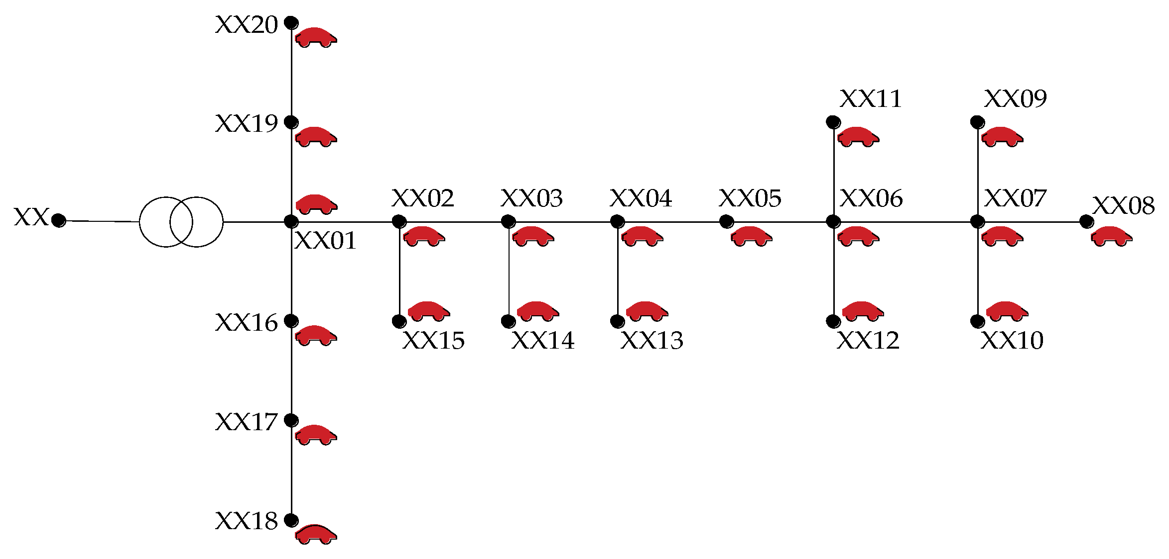
3.1. Test System
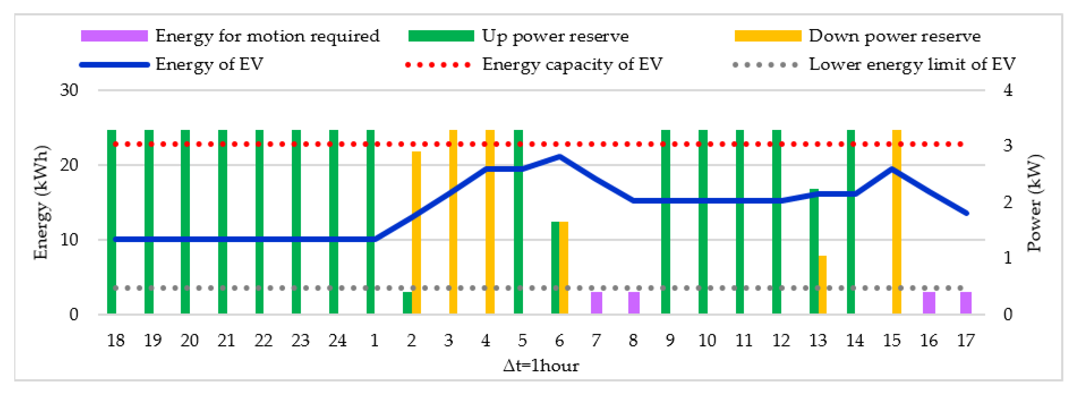
3.1.1. EVs and Reserve Services
3.1.2. Renewable DG Units
3.2. Test Cases
- Case I: EV charging coordination and offering of reserve services during a weekday with , in which it is assumed that the EVs are only available for charging at home between 18:00 h and 07:00 h.
- Case II: EV charging coordination and offering of reserve services during a weekend day with , assuming that most of the owners use their EVs two hours in the morning and two hours at night; therefore, the charging control and reserve service offerings are done between 01:00 h and 06:00 h, 09:00 h and 15:00 h, and 18:00 h and 06:00.
- Case III: EV charging coordination and offering of reserve services during a weekday with ; similar to Case I, which allows studying the scalability of the method.
- Case IV: EV charging coordination and offering of reserve services during a weekend day with , similar to Case II, which allows studying the scalability of the method.
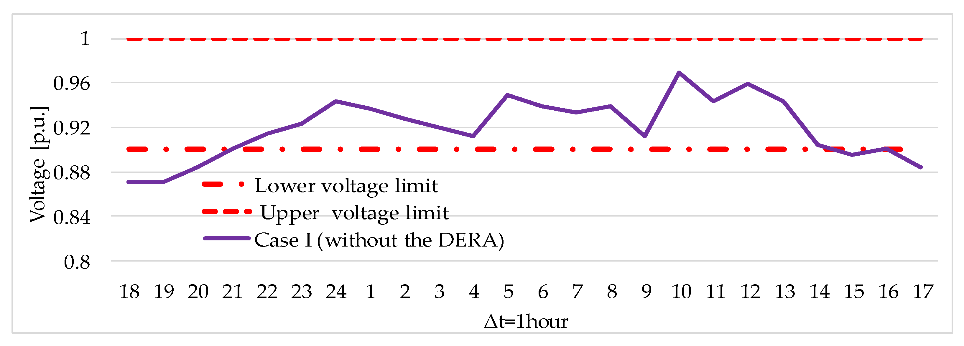
3.2.1. Case I: EV Charging Coordination and Offering of Reserve Services During the Weekday with
3.2.2. Case II: EV Charging Coordination and Offering of Reserve Services During the Weekend with
3.2.3. Case III: EV Charging Coordination and Offering of Reserve Services During the Weekday with
3.2.4. Case IV: EV Charging Coordination and Offering of Reserve Services During the Weekend with
4. Conclusions
Author Contributions
Funding
Conflicts of Interest
Nomenclature
| Indices and Sets | |
| F | Set of phases {A, B, C}. |
| L | Set of circuits. |
| N | Set of nodes. |
| V | Set of vehicles. |
| n, m | Indices of buses. |
| f | Indices of phases. |
| t | Indices of time. |
| v | Indices of vehicles. |
| Parameters | |
| Price of energy from DG units. | |
| Price of up reserve supplied by aggregator. | |
| Price of down reserve supplied by aggregator | |
| Price of energy from PV units. | |
| Price for the charging control. | |
| Cost of the charging power. | |
| Binary parameter corresponding to the state of EV v, 1 when the EV v is on trip and 0 otherwise. | |
| Binary parameter corresponding to the availability for charging of EV v, 1 when the EV v can charge the battery and 0 otherwise. | |
| Duration of the time interval t. | |
| Discretization step for the current of circuit mn. | |
| Number of blocks of the square current piecewise linearization. | |
| Vector of reference phase angles. | |
| Maximum negative deviation of phase angles. | |
| Maximum positive deviation of phase angles. | |
| Shunt susceptance of circuit mn for phase f. | |
| Reactance of circuit mn between phases f and h. | |
| Resistance of circuit mn between phases f and h. | |
| Upper current limit of circuit mn. | |
| Upper and lower voltage limits. | |
| Active power demand at node n for phase f in time interval t. | |
| Reactive power demand at node n for phase f in time interval t. | |
| Active power capacity of DG unit at node n. | |
| Upper/lower reactive power capacities of DG unit at node n. | |
| Lower power factor for the operation of DG unit at node n | |
| Probability of deployment for up and down reserve. | |
| Initial state of charge of EV v. | |
| Energy capacity of EV v. | |
| Lower energy limit of EV v. | |
| Energy for motion required by the owner of EV v. | |
| Charger rated power of the EV v. | |
| Real part of the estimated voltage at node n for phase f in time interval t. | |
| Imaginary part of the estimated voltage at node n for phase f in time interval t. | |
| Real/imaginary part of the estimated voltage at the node and phase associated with EV v in time interval t. | |
| PV power factor available time interval t | |
| Active power capacity of PV. | |
| Upper reactive power capacity of PV. | |
| Lower reactive power capacity of PV. | |
| Minimum power factor for the operation of the PV | |
| Variables: | |
| Real part of the voltage at node n for phase f in time interval t. | |
| Imaginary part of the voltage at node n for phase f in time interval t. | |
| Real part of the current required by a load at node n for phase f in time interval t. | |
| Imaginary part of the current required by a conventional load at node n for phase f in time interval t. | |
| Real part of the current provided by substation at node n for phase f in time interval t. | |
| Imaginary part of the current provided by substation at node n for phase f in time interval t. | |
| Real part of the current in circuit mn for phase f in time interval t. | |
| Imaginary part of the current in circuit mn for phase f in time interval t. | |
| Positive component of the current’s real part in circuit mn for phase f in time interval t. | |
| Negative component of the current’s real part in circuit mn for phase f in time interval t. | |
| Positive component of the current’s imaginary part in circuit mn for phase f in time interval t. | |
| Negative component of the current’s imaginary part in circuit mn for phase f in time interval t. | |
| Square of the current in circuit mn for phase f in time interval t. | |
| Value of the λth block of the piecewise linearization for the current of circuit mn for phase f in time interval t. | |
| Active power produced by DG units at node n in time interval t. | |
| Reactive power produced by DG units at node n in time interval t. | |
| Real part of the current provided by DG units at node n for phase f in time interval t. | |
| Imaginary part of the current provided by DG units at node n for phase f in time interval t. | |
| Active power consumption of EV v in time interval t. | |
| Real part of the current required by the EV v in time interval t. | |
| Imaginary part of the current required by the EV v in time interval t. | |
| Energy of EV v in each time interval t. | |
| Down expected energy offered by EVs v in time interval t. | |
| Up expected energy offered by EV v in time interval t. | |
| Up power reserve offered by the aggregator in the day-ahead reserve market. | |
| Down power reserve offered by the aggregator in the day-ahead reserve market. | |
| Active power injected by PV units at node n in time interval t. | |
| Real part of the current supplied by PV units at node n for phase f in time interval t. | |
| Imaginary part of the current supplied by PV units at node n for phase f in time interval t. | |
| Reactive power generated by PV units at node n in time interval t. | |
References
- REN21. Renewables 2019 Global Status Report; REN21 Secretariat: Paris, France, 2019. [Google Scholar]
- Richardson, D.B. Electric vehicles and the electric grid: A review of modeling approaches, impacts, and renewable energy integration. Renew. Sustain. Energy Rev. 2013, 19, 247–254. [Google Scholar] [CrossRef]
- IEA. Global EV Outlook 2019 to Electric Mobility; Technology Report; IEA: Paris, France, 2019. [Google Scholar]
- Shaaban, M.F.; El-Saadany, E.F. Accommodating high penetrations of pevs and renewable dg considering uncertainties in distribution systems. IEEE Trans. Power Syst. 2014, 29, 259–270. [Google Scholar] [CrossRef]
- Pieltain Fernández, L.; San Román, G.T.; Cossent, R.; Domingo, M.C.; Frías, P. Assessment of the impact of plug-in electric vehicles on distribution networks. IEEE Trans. Power Syst. 2011, 26, 206–213. [Google Scholar] [CrossRef]
- De Quevedo, P.M.; Munoz-Delgado, G.; Contreras, J. Impact of electric vehicles on the expansion planning of distribution systems considering renewable energy, storage, and charging stations. IEEE Trans. Smart Grid 2019, 10, 794–804. [Google Scholar] [CrossRef]
- Arias, N.B.; Hashemi, S.; Andersen, P.B.; Treholt, C.; Romero, R. Distribution system services provided by electric vehicles: Recent status, challenges, and future prospects. IEEE Trans. Intell. Transp. Syst. 2019, 20, 4277–4296. [Google Scholar] [CrossRef]
- Cardona, J.E.; López, J.C.; Rider, M.J. Decentralized electric vehicles charging coordination using only local voltage magnitude measurements. Electr. Power Syst. Res. 2018, 161, 139–151. [Google Scholar] [CrossRef]
- Beaude, O.; Lasaulce, S.; Hennebel, M.; Mohand-Kaci, I. Reducing the impact of EV charging operations on the distribution network. IEEE Trans. Smart Grid 2016, 7, 2666–2679. [Google Scholar] [CrossRef]
- Rezaei, P.; Frolik, J.; Hines, P.D.H. Packetized plug-in electric vehicle charge management. IEEE Trans. Smart Grid 2014, 5, 642–650. [Google Scholar] [CrossRef]
- Franco, J.F.; Rider, M.J.; Romero, R. A Mixed-integer linear programming model for the electric vehicle charging coordination problem in unbalanced electrical distribution systems. IEEE Trans. Smart Grid 2015, 6, 2200–2210. [Google Scholar] [CrossRef]
- Clement, K.; Haesen, E.; Driesen, J. Coordinated charging of multiple plug-in hybrid electric vehicles in residential distribution grids. In Proceedings of the 2009 IEEE/PES Power Systems Conference and Exposition, PSCE 2009, Seattle, WA, USA, 15–18 March 2009; pp. 1–7. [Google Scholar]
- Mukherjee, J.C.; Gupta, A. Distributed charge scheduling of plug-in electric vehicles using inter-aggregator collaboration. IEEE Trans. Smart Grid 2017, 8, 331–341. [Google Scholar] [CrossRef]
- Bessa, R.J.; Matos, M.A. The role of an aggregator agent for EV in the electricity market. In Proceedings of the 7th Mediterranean Conference and Exhibition on Power Generation, Transmission, Distribution and Energy Conversion (MedPower 2010), Agia Napa, Cyprus, 7–10 November 2010; pp. 1–8. [Google Scholar]
- Sarker, M.R.; Ortega-Vazquez, M.A.; Kirschen, D.S. Optimal coordination and scheduling of demand response via monetary incentives. IEEE Trans. Smart Grid 2015, 6, 1341–1352. [Google Scholar] [CrossRef]
- Rivera, J.; Goebel, C.; Jacobsen, H.A. Distributed convex optimization for electric vehicle aggregators. IEEE Trans. Smart Grid 2017, 8, 1852–1863. [Google Scholar] [CrossRef]
- Hu, J.; Yang, G.; Bindner, H.W.; Xue, Y. Application of network-constrained transactive control to electric vehicle charging for secure grid operation. IEEE Trans. Sustain. Energy 2017, 8, 505–515. [Google Scholar] [CrossRef]
- Veldman, E.; Verzijlbergh, R.A. Distribution grid impacts of smart electric vehicle charging from different perspectives. IEEE Trans. Smart Grid 2015, 6, 333–342. [Google Scholar] [CrossRef]
- Clairand, J.M.; Rodriguez-Garcia, J.; Alvarez-Bel, C. Smart charging for electric vehicle aggregators considering users’ preferences. IEEE Access 2018, 6, 54624–54635. [Google Scholar] [CrossRef]
- Wang, S.; Bi, S.; Zhang, Y.J.A.; Huang, J. Electrical vehicle charging station profit maximization: Admission, pricing, and online scheduling. IEEE Trans. Sustain. Energy 2018, 9, 1722–1731. [Google Scholar] [CrossRef]
- Bessa, R.J.; Matos, M.A. Optimization models for an EV aggregator selling secondary reserve in the electricity market. Electr. Power Syst. Res. 2014, 106, 36–50. [Google Scholar] [CrossRef][Green Version]
- Karfopoulos, E.; Hatziargyriou, N. Distributed coordination of electric vehicles for conforming to an energy schedule. Electr. Power Syst. Res. 2017, 151, 86–95. [Google Scholar] [CrossRef]
- Bessa, R.J.; Matos, M.A.; Soares, F.J.; Lopes, J.A.P. Optimized bidding of a EV aggregation agent in the electricity market. IEEE Trans. Smart Grid 2012, 3, 443–452. [Google Scholar] [CrossRef]
- Bessa, R.J.; Soares, F.J.; Peças Lopes, J.A.; Matos, M.A. Models for the EV aggregation agent business. In Proceedings of the 2011 IEEE PES Trondheim PowerTech: The Power of Technology for a Sustainable Society, POWERTECH 2011, Trondheim, Norway, 19–23 June 2011. [Google Scholar]
- Sarker, M.R.; Dvorkin, Y.; Ortega-Vazquez, M.A. Optimal participation of an electric vehicle aggregator in day-ahead energy and reserve markets. IEEE Trans. Power Syst. 2016, 31, 3506–3515. [Google Scholar] [CrossRef]
- Saber, A.Y.; Venayagamoorthy, G.K. Plug-in vehicles and renewable energy sources for cost and emission reductions. IEEE Trans. Ind. Electron. 2011, 58, 1229–1238. [Google Scholar] [CrossRef]
- Seddig, K.; Jochem, P.; Fichtner, W. Integrating renewable energy sources by electric vehicle fleets under uncertainty. Energy 2017, 141, 2145–2153. [Google Scholar] [CrossRef]
- Foroozandeh, Z.; Ramos, S.; Soares, J.; Lezama, F.; Vale, Z.; Gomes, A.; Joench, R.L. A mixed binary linear programming model for optimal energy management of smart buildings. Energies 2020, 13, 1719. [Google Scholar] [CrossRef]
- Soares, J.; Lobo, C.; Silva, M.; Vale, Z.; Morais, H. Day-ahead distributed energy resource scheduling using differential search algorithm. In Proceedings of the 2015 18th International Conference on Intelligent System Application to Power Systems, Porto, Portugal, 11–16 September 2015; pp. 1–6. [Google Scholar]
- Sabillon, C.; Franco, J.F.; Rider, M.J.; Romero, R. Joint optimal operation of photovoltaic units and electric vehicles in residential networks with storage systems: A dynamic scheduling method. Int. J. Electr. Power Energy Syst. 2018, 103, 136–145. [Google Scholar] [CrossRef]
- Akhavan-Rezai, E.; Shaaban, M.F.; El-Saadany, E.F.; Karray, F. Managing demand for plug-in electric vehicles in unbalanced lv systems with photovoltaics. IEEE Trans. Ind. Inform. 2017, 13, 1057–1067. [Google Scholar] [CrossRef]
- Zakariazadeh, A.; Jadid, S.; Siano, P. Integrated operation of electric vehicles and renewable generation in a smart distribution system. Energy Convers. Manag. 2015, 89, 99–110. [Google Scholar] [CrossRef]
- Kirschen, D. A Survey of Definitions and Specifications of Reserve Services; The University of Manchester: Manchester, UK, 2005. [Google Scholar]
- Rua, D.; Issicaba, D.; Soares, F.J.; Rocha Almeida, P.M.; Rei, R.J.; Peças Lopes, J.A. Advanced metering infrastructure functionalities for electric mobility. In Proceedings of the IEEE PES Innovative Smart Grid Technologies Conference Europe, ISGT Europe, Gothenburg, Sweden, 11–13 October 2010. [Google Scholar]
- Qantas Future Planet insights report 2018. Available online: https://www.qantasfutureplanet.com.au/#getinvolved (accessed on 30 November 2019).
- Lopez, J.C.; Franco, J.F.; Rider, M.J.; Romero, R. Optimal restoration/maintenance switching sequence of unbalanced three-phase distribution systems. IEEE Trans. Smart Grid 2018, 9, 6058–6068. [Google Scholar] [CrossRef]
- Fourer, R.; Gay, D.M.; Kernighan, B.W. A modeling language for mathematical programming. Manage. Sci. 1990, 36, 519–554. [Google Scholar] [CrossRef]
- IBM. User’s Manual for CPLEX; CPLEX Division, ILOG: Gentilly, France, 2016; p. 586. [Google Scholar]
- IEEE PES AMPS Distribution Test Feeders, 34-bus Feeder, August 2011. Available online: https://site.ieee.org/pes-testfeeders/. (accessed on 4 December 2019).
- Sarker, M.R.; Pandžić, H.; Ortega-Vazquez, M.A. Optimal operation and services scheduling for an electric vehicle battery swapping station. IEEE Trans. Power Syst. 2015, 30, 901–910. [Google Scholar] [CrossRef]
- Jäger-Waldau, A. PV Status Report 2018; Publications Office of the European Union: Ispra, Italy, 2018. [Google Scholar]


| References | Minimize Charging Cost Managed by Aggregator | Considering EV Users’ Preferences | Maximize Aggregator’s Profits | Reserve Services without Vehicle-to-Grid | DNO Operation | Integration with Renewable Generation | Coordination of EVs and Renewable Generation |
|---|---|---|---|---|---|---|---|
| [13] | ✓ | ✓ | |||||
| [15] | ✓ | ✓ | |||||
| [16] | ✓ | ✓ | |||||
| [17] | ✓ | ✓ | |||||
| [18] | ✓ | ✓ | ✓ | ||||
| [19] | ✓ | ✓ | |||||
| [21] | ✓ | ✓ | ✓ | ✓ | |||
| [22] | ✓ | ||||||
| [23] | ✓ | ✓ | |||||
| [24] | ✓ | ||||||
| [25] | ✓ | ✓ | |||||
| [26] | ✓ | ✓ | |||||
| [27] | ✓ | ||||||
| [30] | ✓ | ✓ | ✓ | ||||
| [31] | ✓ | ✓ | ✓ | ✓ | |||
| [32] | ✓ | ✓ | |||||
| This work | ✓ | ✓ | ✓ | ✓ | ✓ | ✓ | ✓ |
| Cases | During a Week Day | During a Weekend Day | ||
|---|---|---|---|---|
| Case I | ✓ | ✓ | ||
| Case II | ✓ | ✓ | ||
| Case III | ✓ | ✓ | ||
| Case IV | ✓ | ✓ |
| Cases | Total prof6it of DERA ($) | Profit from Selling Energy of PV Units ($) | Profit per Energy Sale of DG Units ($) | Profit from Reserve Services ($) | Charge Control Profit ($) |
|---|---|---|---|---|---|
| Case I | 1362.60 | 755.35 | 468 | 127.45 | 11.81 |
| Case II | 2215.40 | 1548.04 | 486.37 | 169.19 | 11.81 |
| Case III | 1370.93 | 755.35 | 468 | 135.78 | 11.81 |
| Case IV | 2223.78 | 1548.04 | 486.37 | 177.57 | 11.81 |
© 2020 by the authors. Licensee MDPI, Basel, Switzerland. This article is an open access article distributed under the terms and conditions of the Creative Commons Attribution (CC BY) license (http://creativecommons.org/licenses/by/4.0/).
Share and Cite
Guzman, C.P.; Bañol Arias, N.; Franco, J.F.; Rider, M.J.; Romero, R. Enhanced Coordination Strategy for an Aggregator of Distributed Energy Resources Participating in the Day-Ahead Reserve Market. Energies 2020, 13, 1965. https://doi.org/10.3390/en13081965
Guzman CP, Bañol Arias N, Franco JF, Rider MJ, Romero R. Enhanced Coordination Strategy for an Aggregator of Distributed Energy Resources Participating in the Day-Ahead Reserve Market. Energies. 2020; 13(8):1965. https://doi.org/10.3390/en13081965
Chicago/Turabian StyleGuzman, Cindy Paola, Nataly Bañol Arias, John Fredy Franco, Marcos J. Rider, and Rubén Romero. 2020. "Enhanced Coordination Strategy for an Aggregator of Distributed Energy Resources Participating in the Day-Ahead Reserve Market" Energies 13, no. 8: 1965. https://doi.org/10.3390/en13081965
APA StyleGuzman, C. P., Bañol Arias, N., Franco, J. F., Rider, M. J., & Romero, R. (2020). Enhanced Coordination Strategy for an Aggregator of Distributed Energy Resources Participating in the Day-Ahead Reserve Market. Energies, 13(8), 1965. https://doi.org/10.3390/en13081965