1. Introduction
With recent advancements in wearable electronics, numerous wearable devices, such as earbuds, smart rings, and smart watches, have been introduced for both entertainment and medical applications. Due to their light weight, the battery capacity of these devices tends to be low. Hence, these devices require frequent battery recharging, which is undesirable. Ambient energy harvesting has been adapted as a solution to prolong battery life or make these devices self-powered using various harvesting sources [
1,
2,
3,
4,
5]. However, to harvest energy from vibrations produced by human motion, piezoelectric transducers (PZTs) [
6,
7,
8] and triboelectric nano-generators (TENG) [
9,
10] are the most suitable options.
Substantial effort from both the material and circuit research communities has been invested in developing ways to harvest energy from PZTs and TENGs. As these harvesting sources are improved, more energy could be scavenged with high output voltage generated by these sources. Although there have been many harvesting interface designs proposed for low-voltage sources [
11,
12,
13], few designs have been proposed for high-voltage sources. However, recently, a trend of energy harvesting from excitations with high open-circuit voltage (V
OC) generated by PZTs [
6,
14] and TENGs [
9,
10] has been observed. Partial electric charge extraction (PECE) [
14] can theoretically handle excitations with unlimited V
OC. Therefore, this work also focuses on harvesting energy from strong excitations generating high V
OC to maximize energy extraction from PZT.
A PZT can be electrically modelled as a current source (
IP) in parallel with its internal capacitance (
CP) [
13], as shown in
Figure 1. As the deformation force is applied to the PZT, it generates I
P and charges
CP, where the amount of charge (
QP) generated during a single deformation event is proportional to the deformation applied to the PZT. As a harvesting circuit also behaves as a load, PZT can be subjected to different un-charged load capacitances (
CL). Hence, during a single deformation event,
QP does not vary with the load capacitance (
CL) seen by PZT varies if the magnitude of the deformation on the PZT stays the same. PZT-generated energy (
EP) can be measured as the maximum energy which could be harvested from PZT during a single deformation (with or without load). Therefore, the PZT-generated energy (
EP) can be written as follows:
where
VP is the final PZT-generated voltage. The inversely proportional relationship of the load capacitance (
CP +
CL) and
EP in (1) implies that the energy extractable from the PZT can be maximized by decreasing
CL. A smaller
CL results in a faster increment in
VP, which consequently makes the PZT damping force stronger [
4,
14]. Therefore, for the same amount of deformation, more mechanical energy is converted to electrical energy. As a result, by decreasing
CL, more energy can be generated by the PZT, but this also results in higher peak voltage generation.
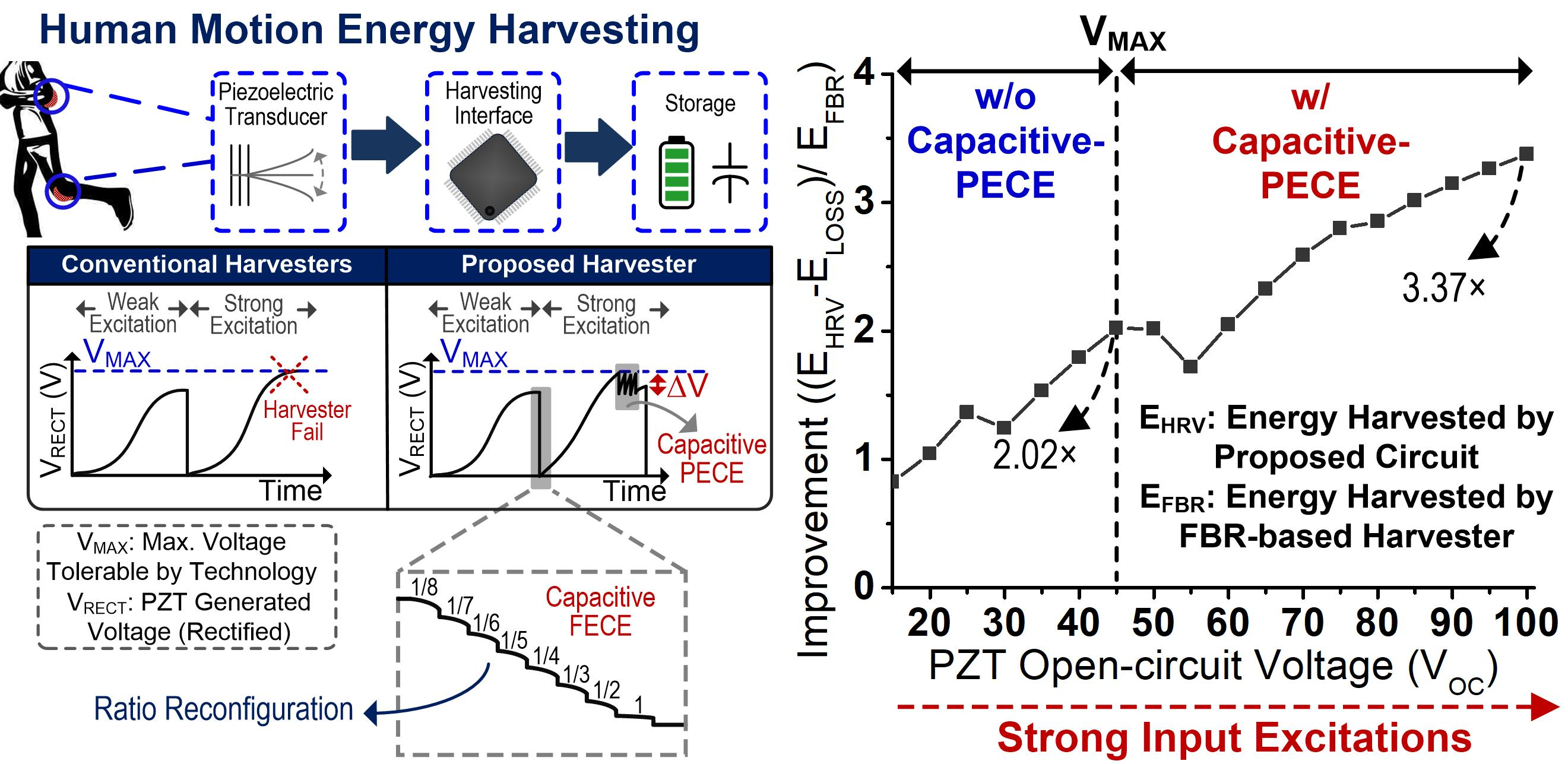
One of the most popular piezoelectric energy harvesting schemes is synchronous switch harvesting on inductor (SSHI) [
13,
15], which can be simplified as shown in
Figure 1a. A negative voltage converter (NVC) is used to rectify alternating PZT output voltage (
VP). As deformation is applied to the PZT,
VP starts to develop across
CP, and NVC starts conduction once
VP becomes greater than V
RECT. A battery (BAT) acts as a temporary storage for the energy harvested from the PZT. At the end of every half-cycle of sinusoidal input excitation (when
VP becomes lower than V
RECT), the polarity of
VP is flipped using either an inductor [
13] (bias-flip) or capacitors [
16,
17] (flipping-capacitors). This polarity flipping is performed to avoid wasting charges already collected on
CP and reaching V
RECT for the next half-cycle earlier, so that NVC conduction (harvesting) period can be maximized. Inductor-based bias-flip harvesters [
13,
15,
18] usually require an inductor and a switch, as shown in
Figure 1a. At the end of deformation,
VP becomes lower than V
RECT, therefore, NVC conduction stops. At this point, S
F is turned on and energy from
CP is transferred to the inductor, and then the inductor transfers this energy back to the
CP. This results in an opposite voltage polarity on
CP.
Flipping-capacitor rectifier (FCR) topology [
16,
17] can also be used to flip the polarity of
CP. These harvesting interfaces require multiple capacitors and switches for this purpose, as shown in
Figure 1a. Energy is transferred from
CP to these capacitors in various configurations until no further energy can be transferred from
CP. At this point,
CP is shorted to drain any remaining energy. Then these flipping capacitors are re-arranged (with the help of switches) to charge
CP with opposite polarity. In the case of strong input excitations (which can generate high V
OC) applied to SSHI or FCR-based harvesters [
13,
15,
16,
17,
18],
VP does not change much, due to fixed energy storage voltage (V
RECT), which acts as protection against strong input excitations. However, keeping storage voltage limited significantly reduces the energy extraction from the PZT [
19], since it decreases PZT damping force, and hence lower energy extraction.
Another popular harvesting scheme is synchronous electric charge extraction (SECE) [
7,
20], as shown in
Figure 1c. SECE-based circuits also require an NVC to deal with the alternating output voltage of the PZT. In SECE-based circuits, during a mechanical deformation on PZT,
IP keeps charging
CP until
VP reaches its peak, as shown for first half-cycle of waveform in
Figure 1c. S
1 is turned on at this point to transfer energy from
CP to inductor until
VP becomes 0 V. Then S
1 is turned off and S
2/S
3 are turned on to transfer energy from inductor to the battery (BAT). Although this scheme can handle the PZT-generated irregular input as energy is harvested from the PZT at the peak voltage, in the case of strong input excitation with high V
OC,
VP can exceed the maximum voltage tolerated by technology (V
MAX), which can damage the harvesting interface.
Recently a new scheme, referred to as partial electric charge extraction (PECE) [
14], was introduced to deal with the excitations with high V
OC of the PZT. In this scheme, PZT-generated charges are partially extracted (
VP decreases by ∆V) from the PZT once
VP approaches V
MAX. PECE allows operation without any load capacitor (
CL = 0); therefore, the maximum amount of energy from the PZT can be extracted while keeping
VP high enough until the end of the PZT deformation. Keeping
VP high results in a higher damping force on the PZT, hence extracting more energy until the end of the peak detection. However, this scheme still reduces
VP by 8 V (∆V) during a single PECE cycle, decreasing the damping force of the PZT. In addition, this scheme requires a bulky inductor, which limits the on-chip implementation. Therefore, to address these shortcomings, a fully integrated capacitor-based partial electric charge extraction system is proposed in this work. The switched capacitors in the proposed work do not act as a load during energy extraction from the PZT and are only used to extract energy from the PZT at the peak of
VP or during a PECE cycle. Unlike prior flip-capacitor-based harvesters, the proposed circuit can handle strong excitations with very high V
OC, while keeping
VP below V
MAX. In addition, unlike [
14], the proposed capacitive PECE scheme aims to minimize the reduction in
VP during a single PECE cycle (∆V = 1 V) to keep the electrical damping force of the PZT high, which results in higher energy extraction from the PZT.
The remainder of the paper is organized as follows:
Section 2 briefly explains the top-level implementation of the proposed piezoelectric harvesting interface. The implementation details of the harvesting controller and sub-blocks are also elaborated in
Section 2. In
Section 3, the simulation results and comparison with prior works are described.
Section 4 concludes the paper.
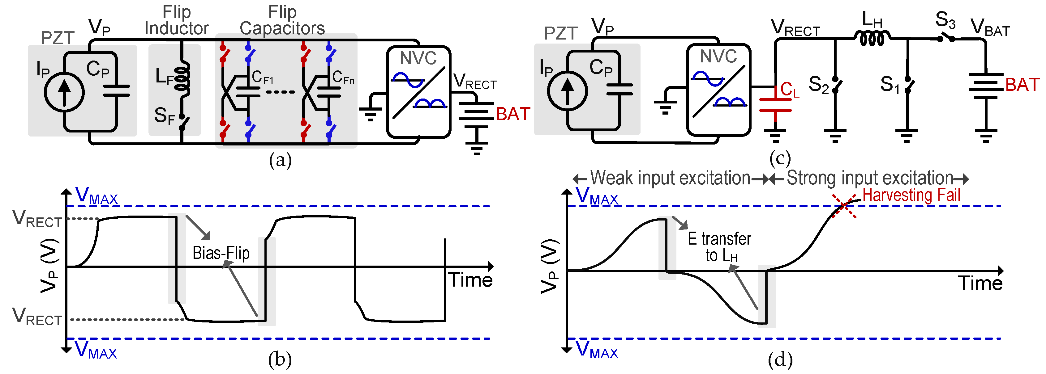
2. Capacitive PECE Harvesting Interface Implementation
Pulses generated by a PZT attached to a human body can be irregular. This means that the voltage generated by a PZT can also be random and can exceed the maximum voltage tolerated by the CMOS process used for IC fabrication. Therefore, a fully integrated harvesting interface to handle irregular input excitations is proposed in this work. A simplified circuit diagram of the proposed piezoelectric harvesting interface is shown in
Figure 2a. To maximize the energy extraction from the PZT, no external load capacitor is added [
14,
19]. As the PZT is deformed,
CP is charged until
VP reaches its peak (V
PK). For weak input excitation,
VP remains lower than V
MAX, and the charges are completely extracted at V
PK, as shown in
Figure 2b, which will be referred to as full electric charge extraction (FECE) in the rest of the paper. In the case of strong input excitation, where
VP can exceed the V
MAX, PECE is activated to extract a partial amount of charges from
CP, and
VP decreases by PECE step voltage (∆V). Here, ∆V is kept to a minimum to keep the electric damping force of the PZT high and to generate maximum energy after a PECE cycle [
14,
19]. Multi-ratio switched capacitors are utilized to harvest energy from the PZT and transfer it to the battery. After a single PECE cycle,
VP keeps increasing until the peak voltage is detected, where FECE is activated (
Figure 2b). In the case of FECE, energy is extracted in multiple steps with different ratios to increase the conversion efficiency during the down-conversion of
VP.
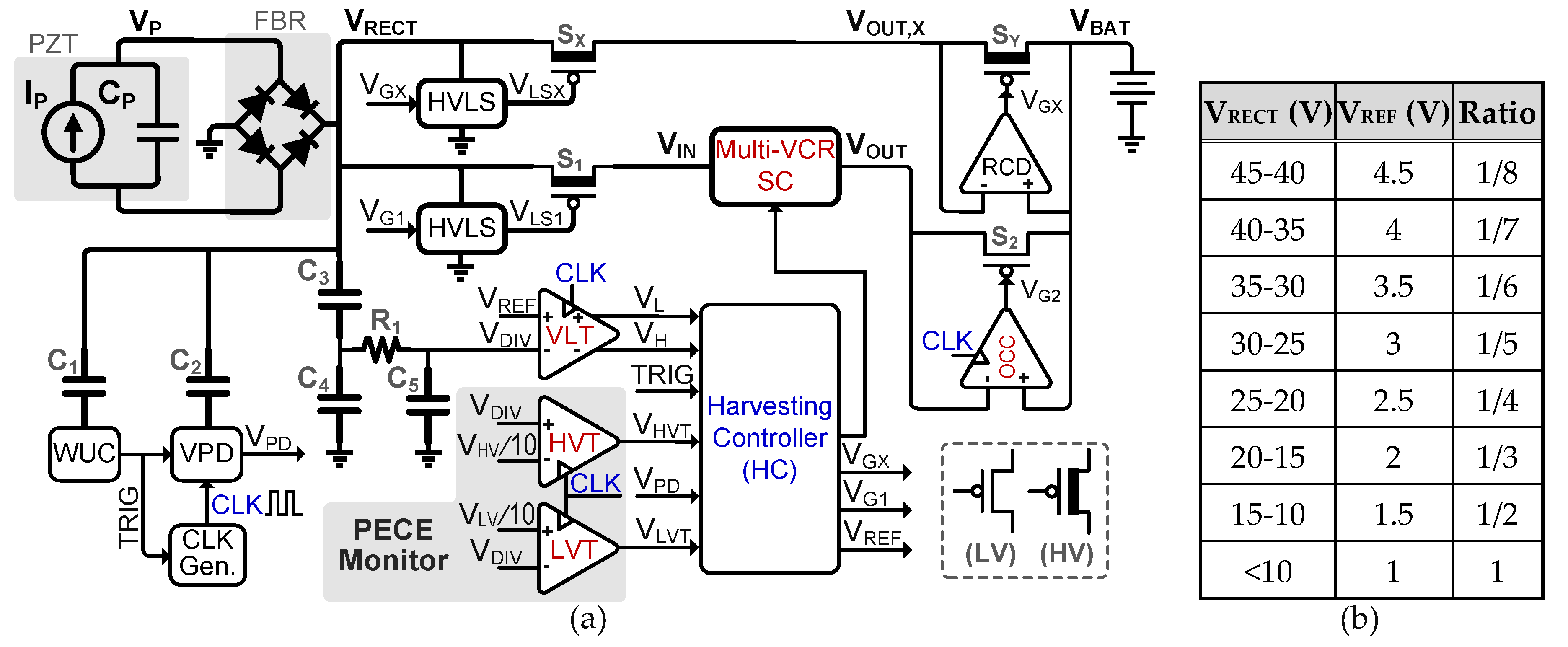
The top-level circuit implementation details of the proposed harvesting interface are shown in
Figure 3a. A full-bridge rectifier (FBR) is utilized to deal with the alternating output of the PZT. The rectified output (V
RECT) is monitored with a wake-up controller (WUC) through a coupling capacitor (C
1), which is an integrated high-voltage capacitor. The WUC, whose detail is discussed in
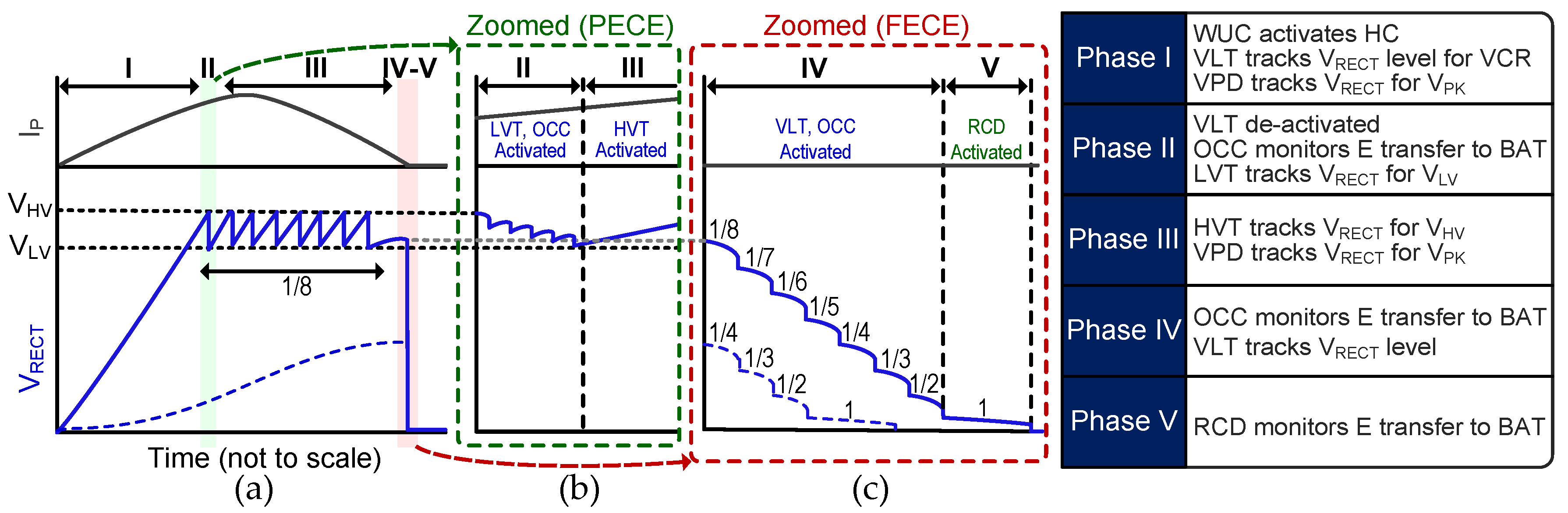
Section 2.2, detects the deformation of the PZT by sensing the input voltage rising over a threshold voltage. As soon as the energy generation by the PZT is detected, the WUC activates the rest of the harvesting circuit to enable the harvesting operation (Phase I in
Figure 4a). Otherwise, all the other circuits are power gated to minimize the static power loss. When input is detected, the WUC triggers the TRIG signal to activate the clock generator and voltage peak detector (VPD) [
8] to track the PZT voltage and determine when the V
RECT reaches its peak voltage (V
PK). To deal with high PZT voltage, the VPD is also interfaced with V
RECT using a high-voltage capacitor, C
2.
During PZT deformation, a PZT-generated current (I
P) charges the internal capacitance (
CP). To maximize the energy extraction with maximized output voltage (
VP) [
19], the load capacitance seen by the PZT is minimized by keeping S
1 and S
X turned off. A clocked voltage-level tracker (VLT) is also activated to track the voltage level of
VP, and to initiate partial charge extraction in case
VP approaches V
MAX. Two on-chip high-voltage capacitors, C
3 (5 pF) and C
4 (45 pF), are utilized to generate fractional peak voltage (with a division ratio of 10:1) to interface VLT with the high voltage of the PZT. R
1 and C
5 act as a low-pass filter during the high-frequency charge extraction cycles. The VLT keeps comparing the divided voltage (V
DIV) with an adjustable reference voltage (V
REF) until the end of the harvesting operation. This adjustable V
REF (explained in
Section 2.1) is necessary to determine the correct conversion ratio to achieve stable V
OUT with maximum conversion efficiency. For example, a conversion ratio of 1/7 would be used if V
RECT is between 35 V and 40 V. In this case, V
REF is set to 4.0 V to monitor if V
RECT exceeds 40 V. When it does exceed 40 V, the conversion ratio is adjusted to 1/8 and V
REF is increased to 4.5 V, to detect if V
RECT approaches 45 V. In this manner, the VLT continues to monitor V
RECT and determine the proper conversion ratio and V
REF, as shown in
Figure 3b. The harvesting controller (HC) increases V
REF during bending deformation, whereas it decreases V
REF during harvesting operation to reconfigure the ratio according to the V
RECT level.
A multiple-voltage conversion-ratio switched-capacitor (Multi-VCR SC) DC-DC converter [
21] is utilized to down-convert V
RECT and transfer the PZT-generated energy to the battery (5 V). In case V
RECT exceeds V
MAX (45 V), partial charge extraction is activated to partially lower V
RECT and protect the integrated circuits, as shown in
Figure 4b (Phase II). A carefully designed high-voltage level shifter (HVLS), similar to the one used in [
21], is used to turn on S
1. A clocked output control comparator (OCC) is also activated to turn on S
2 only when V
OUT > V
BAT. In a single PECE cycle, the Multi-VCR SC converter is configured to a ratio of 1/8 and the energy transfer to the battery is stopped once
VP is decreased by the PECE step voltage (∆V = 1 V). ∆V is kept small to keep the damping force of the PZT higher, which results in higher energy extraction post-PECE, which is similar to the approach taken in [
14].
To perform PECE operations, the PECE monitor block is activated when the VLT detects V
RECT reaching V
MAX and operates until a peaking event is detected with V
RECT. The VLT is deactivated at this point and is only reactivated once peak voltage is detected. The PECE monitor block consists of a high-voltage tracker (HVT) and low-voltage tracker (LVT), both of which are clocked comparators. As soon as the first PECE cycle is activated, charges are extracted from the PZT to the battery, and the LVT determines the end of a single PECE operation by detecting when V
RECT approaches the lower threshold V
LV, as shown in
Figure 4a,b. During a single PECE cycle, the Multi-VCR SC converter keeps extracting charges from the PZT with a fixed VCR of 1/8, since the voltage variation during this process is relatively small, as shown in
Figure 4. Upon the completion of a PECE cycle (Phase III activated), the HVT starts monitoring V
RECT again and activates another PECE cycle if it reaches V
MAX (V
HV in
Figure 4a,b) again. Until the peaking event is detected for V
RECT, multiple PECE cycles can be activated for strong input excitations.
Once the peaking event of V
RECT is detected, FECE is activated (Phase IV). The conceptual waveform of an FECE cycle is shown in
Figure 4c. S
1 and S
2 are turned on to interface the Multi-VCR SC converter with V
RECT, just like a PECE cycle. FECE starts with the conversion ratio corresponding to V
REF (
Figure 3b) recorded before peak detection, whereas V
REF is adjusted to the lower value on the table. For example, when V
RECT is near V
MAX, a configuration ratio of 1/8 is selected for down-conversion as shown in
Figure 4c, and V
REF is set to 4 V. The VLT keeps monitoring V
RECT, and the 1/8 configuration is maintained until V
RECT drops below 40 V, which can be detected by monitoring V
DIV dropping below 4 V. To maintain the conversion efficiency, the Multi-VCR SC converter ratio is changed to 1/7, and V
REF is changed to 3.5 V, to modify the conversion ratio once it reaches the lower limit (mentioned in
Figure 3b) of 35 V. Similar steps are repeated for further down-conversion of V
RECT: VLT keeps tracking V
RECT until the end of the harvesting operation, and the conversion ratio is changed to keep the conversion efficiency high. Thus, energy harvesting occurs in multiple steps (
Figure 4c). Once
VP reaches <10 V, S
1 and S
2 are turned off. At this point, S
X and S
Y are turned on to transfer the remaining charges directly to the battery (Phase V). A reverse current detector (RCD) is activated to monitor this energy transfer and block reverse current. The dashed line of V
RECT in
Figure 4a shows an example (of weak input excitation) when the peak voltage is detected without PECE activation and hence the Multi-VCR SC converter starts the down-conversion from the lower VCR, as shown in
Figure 4c. The sub-block implementation details are explained in the following sub-sections.
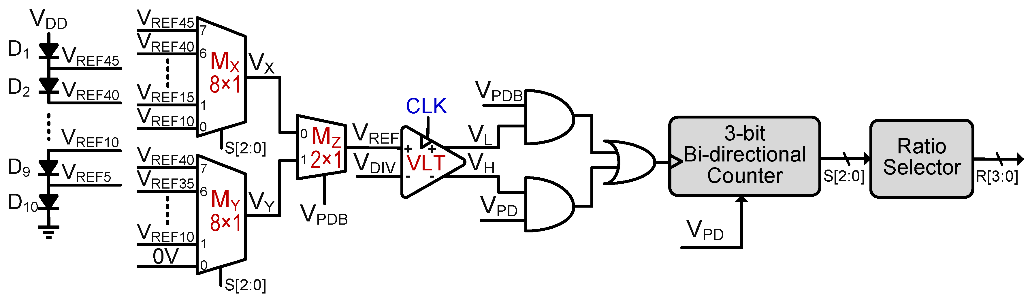
2.1. Harvesting Controller (HC)
The Harvesting controller is the key block that controls the overall sequence of the harvesting operation. Based on several comparison results (from VLT, HVT, LVT), it determines which harvesting step should be initiated, and when. As explained earlier, an adjustable V
REF is required to determine the harvesting step; therefore, a diode stack, as shown in
Figure 5, is used to generate multiple reference voltages with 500 mV steps. These multiple reference voltages are fed to 8 × 1 analog-multiplexers (M
X, M
Y), where the output of M
X (V
X) is selected as V
REF by another 2 × 1 analog-multiplexer (M
Z) if the PZT voltage is increasing (before peak detection). The output of the other multiplexer M
Y (V
Y) is utilized (by M
Z) as V
REF if the PZT voltage is decreasing (after peak detection). The VLT keeps tracking the V
RECT level by comparing the divided version of V
RECT (V
DIV) with V
REF, and the HC makes a decision based on the output of the VLT. During this level tracking, the VPD also remains active until the PZT voltage peaking event, which means the output of the VPD (V
PD) also remains high until the harvesting operation is initiated.
A 3-bit bi-directional counter is utilized to adjust VREF and determine the proper conversion ratio for the Multi-VCR SC converter during harvesting operation. When VPD is high, its inverted output, VPDB, remains low; therefore, initially VX is selected as the input for MZ. Initially, VREF (VX) is adjusted to VREF10 (1 V), which corresponds to VRECT < 10 V; hence, the initial conversion ratio remains fixed at 1. Once VRECT exceeds 10 V, the VDIV > VREF condition is met, and VH goes high to increment the bi-directional counter, which means VREF (VX) is incremented to VREF15 (1.5 V), and the conversion ratio is changed to 1/2. The HC keeps repeating these steps to increment VREF and the counter until either a peaking event or PECE condition is detected. The output of the ratio selector, which is a simple encoder, is applied to the Multi-VCR SC converter only during harvesting operation, to avoid any switching loss. After peaking event detection, VPD becomes low (VPDB high), which means VY becomes VREF. Here, VREF starts with voltage level immediately lower than VPK, which means VL is used to decrement the conversion ratio whenever the VLT detects that VDIV < VREF. The HC keeps repeating the VCR down-conversion operation until VRECT < 10 V, the point at which a direct connection between VRECT and battery is formed, and RCD is activated to determine the end of the harvesting operation. Once the harvesting operation ends, S [2:0] is reset and VREF is set to VREF10 (1 V) for the next harvesting operation.
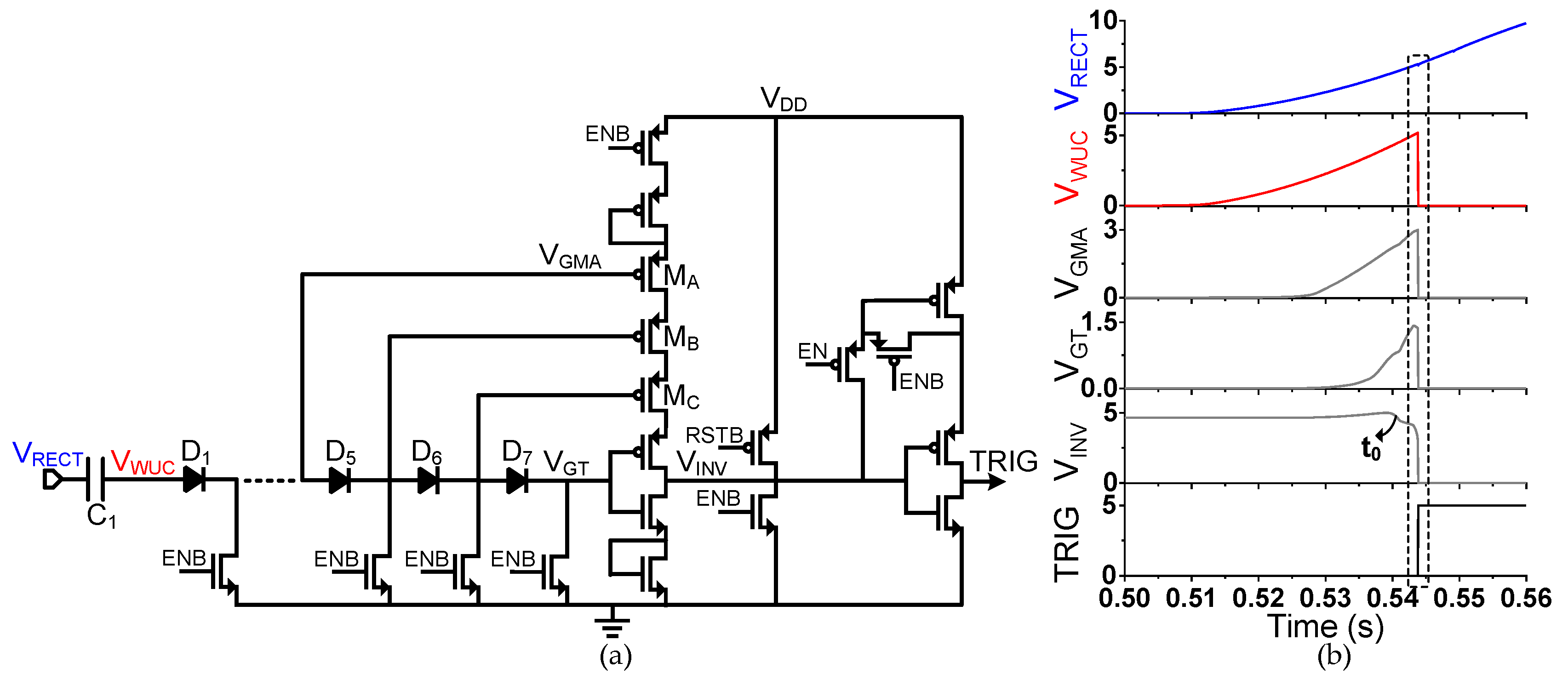
2.2. Wake-Up Controller (WUC)
To keep the static power loss low, the harvesting circuit needs to be activated only when deformation is applied to the PZT. A low-power WUC (based on [
8]) detects this deformation and activates the harvesting operation, as shown in
Figure 6. The WUC needs to trigger (TRIG) when the PZT voltage exceeds a certain threshold voltage (V
TH). However, when there is a slow increment in PZT voltage or in response to some noise, V
RECT can reach near V
TH, which can activate the short-circuit current from V
DD, wasting energy. Therefore, in this work, M
A–M
C are added to reduce power consumption near V
TH. As V
RECT increases, so does V
WUC; therefore, the voltage V
GMA starts to increase, increasing the gate voltage of M
A and thereby reducing the gate-to-source voltage difference (V
GS), and hence reducing the leakage current. A similar operation is performed with M
B and M
C. During the mechanical deformation of the PZT, as V
GT starts to increase, V
INV starts pulling down (t
0 on
Figure 6b). Further increase in V
GT triggers the TRIG signal faster (due to weaker pull-up), as shown by the box (marked with dashed lines) in
Figure 6b. This scheme results in lower power consumption during the static mode as well as the trigger mode (
VP > V
TH).
3. Results and Discussion
The proposed harvesting circuit was designed and simulated with Cadence Spectre using commercial 350 nm BCD process (
Supplementary Materials Figure S1). A PZT source with 20 nF internal capacitance was used for simulations, and V
MAX of the given process was assumed to be 45 V.
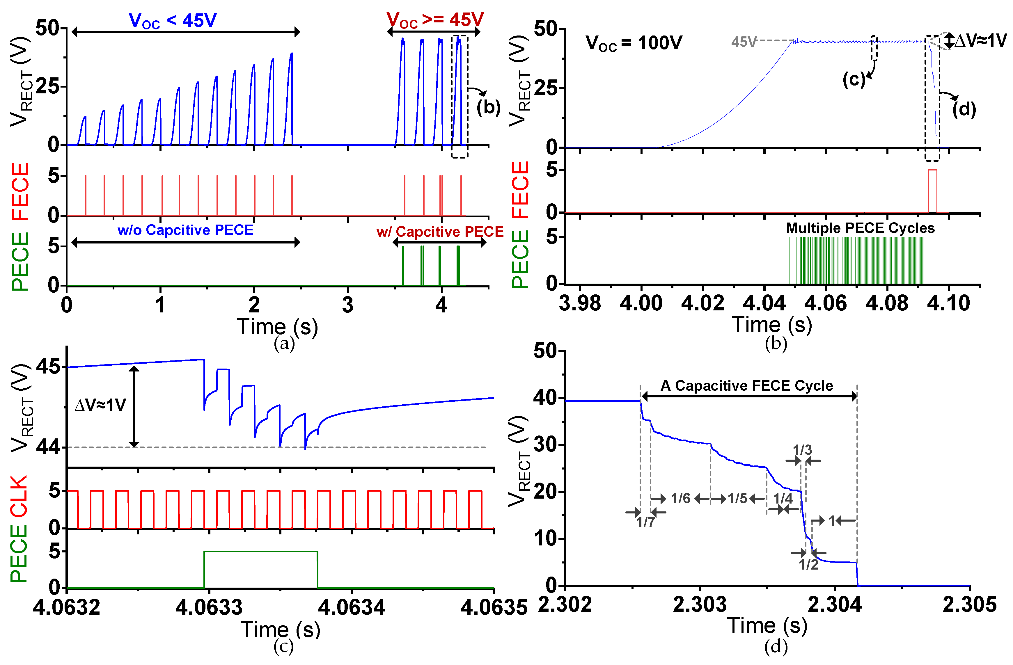
Figure 7a shows the simulation results using the proposed harvesting circuit with a gradual increase in input excitations. With weaker input excitations, the PZT-generated voltage (V
OC) remains lower than V
MAX; therefore, only capacitive FECE is activated, and charges are fully extracted from PZT whenever the peaking event is detected. However, as input excitations become stronger, the PZT voltage rises above V
MAX, at which point capacitive PECE is activated to keep V
RECT below V
MAX.
Figure 7b shows one of the cases of stronger excitations where V
OC exceeds V
MAX. As V
RECT approaches V
MAX, capacitive PECE is activated, and charges are partially extracted from the PZT until V
RECT decreases by ∆V (1 V). V
RECT keeps increasing after each PECE cycle, and multiple PECE cycles are activated before the final peak detection, where FECE is activated to fully discharge the PZT.
Figure 7c shows a zoomed waveform of a single capacitive PECE cycle. As the V
RECT >= V
MAX condition is met, PECE is activated (around
t = 4.0633 s). S
1 is turned on, and the Multi-VCR SC converter is activated with a fixed VCR of 1/8. S
2 is closed to transfer energy to the battery until V
RECT decreases by PECE step voltage (∆V = 1 V in this case). The PZT voltage keeps increasing until a peaking event is detected, at which point the charges are completely extracted from the PZT with FECE operation. A zoomed waveform of a capacitive FECE cycle is shown in
Figure 7d. In this case, V
OC is lower than 40 V; therefore, a VCR of 1/7 is initially applied for efficient voltage conversion. As
CP is discharged, V
RECT is decreased, and the Multi-VCR SC converter is reconfigured to lower ratios until V
RECT becomes lower than 10 V. At this point, the minimum VCR of 1/2 becomes inefficient; hence a direct connection between
CP and the battery is formed by turning off S
1/S
2 and turning on S
X/S
Y. The direct energy transfer is monitored by the RCD to block the reverse current (by turning off S
X/S
Y) when V
RECT approaches 5 V. In the end,
CP is fully discharged by shorting, which marks the end of the capacitive FECE cycle.
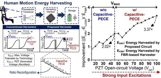
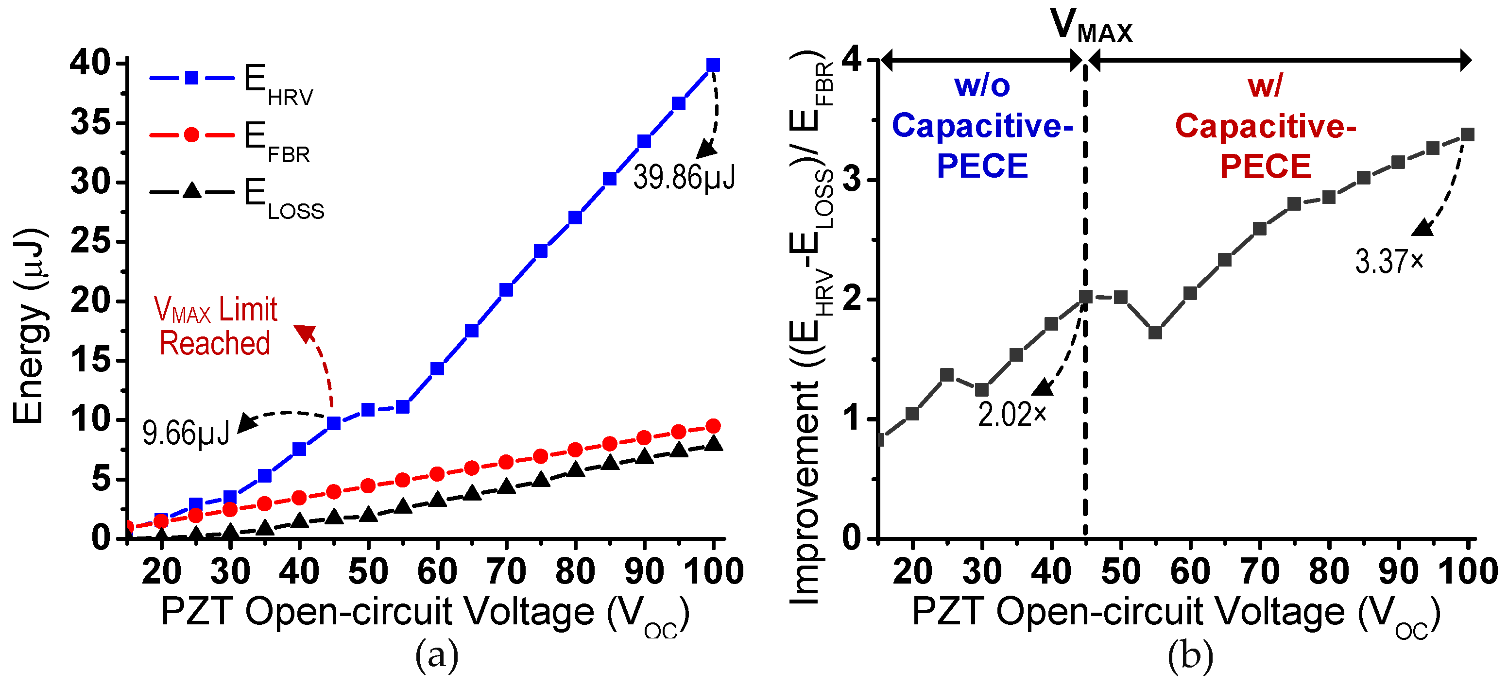
The performance and effectiveness of the proposed harvesting interface is evaluated with comprehensive simulations, as shown in
Figure 8. The evaluation is performed with varying strengths of input excitations, whose strength can be represented with open circuit voltage (V
OC). The energy harvested using the proposed harvesting interface is shown as E
HRV, and the energy consumed from external power source V
DD for circuit operation during a single harvesting operation is shown as E
LOSS. Since the FBR-based harvesting scheme is conventionally used as a benchmark, the energy harvested using an FBR-based circuit is also measured and shown as E
FBR.
Figure 8a compares E
HRV and E
FBR, and it clearly shows that for high open-circuit voltages, the proposed harvesting circuit can extract more energy, compared to an FBR-based scheme.
Figure 8b shows the relative improvement in amount of energy harvested with the proposed harvesting interface, compared to an FBR-based harvester. Up to 3.37 × energy extraction improvement is observed with input excitation with V
OC of 100 V, which clearly shows the effectiveness of the proposed circuit. In addition, energy harvesting from input excitations with V
OC > 45 V would not have been possible without a PECE harvesting scheme.
Table 1 compares the proposed harvesting interface with state-of-the-art harvesting circuits proposed for kinetic energy harvesting. Unlike prior flipping-capacitor-based harvesters [
16,
17], the proposed harvesting interface maximizes the PZT output voltage (to its peak voltage), resulting in stronger mechanical damping and higher energy extraction without the usage of large capacitors for bias flipping. Prior works [
6,
7,
14,
15,
20] require a bulky off-chip inductor, whereas the proposed circuit needs eight high-voltage capacitors (0.75 nF each), which can be integrated on chip. The proposed harvesting interface can handle strong input excitations with high open-circuit voltage (simulated results shown for up to 100 V) thanks to the capacitive-PECE technique, while achieving 3.37 × energy extraction improvement compared to an FBR-based harvester. A fair comparison with an inductive-PECE scheme [
14] on maximum input voltage is not possible, because, theoretically, both circuits can harvest energy from excitations with unlimited open-circuit voltage as long as the input current is within a manageable range. Proposed harvesting interface achieves the goal of implementation of the fully integrated capacitive PECE technique. Unlike many other PZT harvesting circuits, the PECE approach allows the harvesting of energy from strong input excitations with high V
OC, potentially higher than the maximum voltage allowed by integrated circuit. The proposed harvesting interface successfully down-converts PZT-generated voltage to 5V, and also achieves maximum harvested energy per cycle compared to prior-works. Thanks to the PECE, the proposed harvesting interface maintains high energy extraction improvement, compared to the FBR-based harvesting system.


