Article

Performance Enhancement of Direct Torque-Controlled Permanent Magnet Synchronous Motor with a Flexible Switching Table

1
Key Laboratory of More Electric Aircraft Technology of Zhejiang Province, University of Nottingham Ningbo China, Ningbo 315100, China
2
PEMC Group, University of Nottingham, Nottingham NG7 2RD, UK
*
Author to whom correspondence should be addressed.
Energies 2020, 13(8), 1907; https://doi.org/10.3390/en13081907
Submission received: 7 March 2020 / Revised: 2 April 2020 / Accepted: 8 April 2020 / Published: 14 April 2020
(This article belongs to the Section F: Electrical Engineering)

Abstract

:
In this paper, a flexible switching table (FST) for direct torque control (DTC) of permanent magnet synchronous motors (PMSMs) was proposed to enhance the steady-state and dynamic performances of the drive system. First, the influence of each converter output voltage vectors on the torque and stator flux deviation rates was analyzed to assess the voltage selection strategies of the conventional STs and their impact on the DTC system’s performance. Then, a new flexible ST was proposed which uses a simple algorithm to adaptively select the appropriate voltage vector for two of its states according to the system operating condition. The effectiveness and feasibility of the proposed FST were verified through a comparative evaluation with the conventional STs using experimental results obtained from a 0.75 kW PMSM drive system.

1. Introduction

In recent years, permanent magnet synchronous motor (PMSM)-based drive systems are extensively adopted in a variety of applications, such as electric propulsion systems and robotics, because of its high power density, high efficiency, and maintenance-free operation [1]. To allow high-performance operation for PMSM, several control methods are presented in literature such as current vector control (CVC), direct torque control (DTC), and model predictive control (MPC) [2,3,4]. Direct torque control becomes attractive for applications that desire fast torque response and strong robustness with the motor parameter variation [5,6]. These are because the DTC technique eliminates the pulse width modulation (PWM) and the rotor parameters dependence as compared with the widely used CVC techniques. Moreover, elimination of the current control loops and their associated coordinates transformation makes sensorless control of PMSM using DTC achievable if the initial rotor position is approximately estimated to calculate the initial stator flux linkage [7]. However, efforts are dedicated to solve performance issues of DTC, such as high torque and stator flux ripples, and the variable switching frequency of the inverter [8,9,10,11].
Figure 1 shows the block diagram of the switching table (ST)-based DTC scheme. The basic idea of this control method depends on selecting appropriate voltage vector from an ST to force the torque and stator flux to follow predefined reference values ( T e r e f , ψ s r e f ). The selection of the voltage vector relies on detecting the required deviation direction in the torque and the stator flux ( K T , K ψ ) by two hysteresis regulators, and the angular position of the stator flux vector ( θ s ) using flux estimator [6].
Compared with other DTC schemes, such as deadbeat DTC [12], model predictive DTC (MPDTC) [13,14], fuzzy logic-based DTC [15], and duty ratio modulation based DTC (DDTC) [16], the main advantages of the ST-based DTC are fewer computation requirements, ease of implementation, lower switching frequency even if a higher sampling frequency is used, and more robustness against the parameter variation of the machine [2]. However, these advantages are provided at the cost of higher torque and stator flux ripples and the need for a high sampling rate for digital implementation to provide adequate steady-state performance. These are because the selected voltage vector from the ST is applied for the whole sampling period [6].
Different STs are proposed in References [17,18,19,20,21] which vary according to the number of levels of the torque hysteresis controller, the inclusion of the zero voltage vectors (ZVVs), and sector boundaries. In 1997, the application of DTC in PMSM was firstly reported in Reference [18] using a two-level (2L) hysteresis torque controller and an ST that employs only the six active voltage vectors (AVVs) of the two-level voltage source inverter (2L-VSI). In Reference [19], the role of ZVVs in DTC systems of PMSM was investigated, and a DTC strategy was proposed using a three-level hysteresis torque comparator and an ST similar to the basic one which was proposed in Reference [17] for the induction motors (IMs). It was revealed in Reference [19] that the torque ripple of the DTC system can be reduced using ZVVs, because they cause torque reduction with a lower rate than that of the AVVs. A modified version of the basic ST is presented in Reference [20] by redefining the boundaries of the sectors where the stator flux vector is located. The main control objective of this modification was the torque ripple reduction; however, it caused a higher stator flux ripple. The effect of using ZVVs at only one state of the ST was studied in Reference [21], and the simulation results show that it can be beneficial for the steady-state performance and the average switching frequency. However, the dynamic response of the torque was not considered. In addition, according to the analysis of the ZVVs’ effect on the DTC of the PMSM presented in Reference [19], it is supposed to deteriorate when a torque reduction is commanded. Moreover, from a practical point of view, the control algorithm has to be insensitive to the direction of rotation, but the proposed ST in Reference [21] will not allow the motor speed reversal, as it employs ZVVs to reduce the torque and the stator flux.
In this paper, the torque and stator flux deviations with the different output voltage vectors were analyzed to reveal the pros and cons of employing the aforementioned STs in PMSM DTC. Then, a new flexible ST and a simple voltage selection algorithm were proposed for optimal utilization of both ZVVs and AVVs to improve the overall performance. Furthermore, these STs were comparatively evaluated in terms of different performance indices through experimental results obtained from a 0.75 kW PMSM drive system. Finally, some conclusions were drawn to summarize the results.

2. Analysis of DTC for PMSM

2.1. Machine Model and DTC Concept

In DTC, the electrical dynamic behavior of a surface-mounted PMSM is preferable to be represented in the stationary reference frame (αβ) to avoid complex rotor frame transformation, as follows [22]:
V s α β = R s I s α β + d ψ s α β d t ,
ψ s α β = L s I s α β + ψ r α β ,
T e = 3 p 2 Im ( ψ s α β I s α β ) ,
where ψ s α β = ψ s e j θ s and ψ r α β = ψ f e j θ r . Substituting (2) into (3), the torque equation can be rewritten as follows:
T e = 3 p ψ f ψ s 2 L s   sin ( θ s θ r ) ,
while the stator flux can be reformulated as shown in (5) after integrating Equation (1) for a sampling period of Ts.
ψ s α β = V s α β T s R s t 0 t 0 + T s I s α β   d t + ψ s α β 0 ,
Equation (4) implies that the torque can be controlled by changing the angle between the stator flux vector and the rotor ( δ = θ s θ r ). Because the electrical time constant of the machine is normally much smaller than the mechanical time constant, this angle can be changed by manipulating the stator flux vector. According to (5), the stator flux vector moves in the direction of the stator voltage vector ( V s α β ) as illustrated in Figure 2. Thus, both the torque and the stator flux amplitude can be controlled by selecting the proper voltage vector from the eight voltage vectors (V0–V7) that are provided by a 2L-VSI. To achieve that, the torque and the stator flux are first estimated using either the voltage or the current models given by (1) and (2), respectively [23]. Then, two hysteresis regulators are used to decide whether an increase or decrease in the controlled variables is required depending on the hysteresis band limits (±h) and the error between the estimated and reference values. Based on the hysteresis controllers’ outputs and the sector where the stator flux vector is located, that can be one of six sectors (S1–S6), the voltage vector is selected from an ST.

2.2. Conventional STs

There are four main STs utilized in DTC of PMSM, as shown in Table 1, which are designated as BST, MBST, AST, and ZST, respectively, in this work for simplicity. They vary in terms of the number of levels of the torque hysteresis controller, the inclusion of the ZVVs, and sector boundaries. The basic switching table (BST) was originally proposed in Reference [17] for the IM and applied for PMSM in References [2,19]. This ST needs a three-level hysteresis controller for the torque and includes both AVVs (V1–V6) and ZVVs (V0, V7). In this case, if both of T e and ψ s are required to rise ( K ψ   = 1, K T   = 1), the AVVs that keep ψ s rotating in the same direction are employed based on the xth sector where the stator flux vector is located. Therefore, the angle δ increases and the actual torque increases as well. Once the estimated value of T e reaches the reference value ( K T = 0), the ZVVs are selected. If the actual T e becomes greater than the reference value ( K T   = −1), the AVVs that make ψ s moving in the reverse direction are selected to reduce δ.
For the aim of torque ripple reduction, the modified basic switching table (MBST) was developed in Reference [20] which follows the same conditions of BST, but the AVVs are selected based on modified sector boundaries which become on the six AVVs themselves instead of those of the traditional sector shown in Figure 1. Other studies, such as Reference [18], show that DTC of PMSM can work well only when the ZVVs are eliminated as in AST, where a 2L hysteresis torque regulator is required. The reason for this is the reduction of ψ s due to the stator resistance drop when a ZVV is applied, according to (5). As a result, the stator flux will behave in a way that contradicts what is practically needed at the state “ K ψ   = 1, K T   = 0” of either BST or MBST.
In contrast to the previous viewpoint, the rule of ZVVs in PMSM DTC was comprehensively investigated in Reference [19], and it was concluded that the inclusion of ZVVs in ST can improve the system performance. Consequently, ZST was proposed in Reference [21] where the torque needs a 2L hysteresis controller, and ZVVs are employed in case both of the torque and stator flux amplitude are required to decrease ( K ψ   = −1, K T = −1). Additionally, it was compared with BST and showed better steady-state performance with reduced average switching frequency and torque ripple. Owing to the inconsistent viewpoints for the voltage vector selection employed in the conventional STs, a comparative evaluation for their performance can be useful for identifying the main features and drawbacks of each.

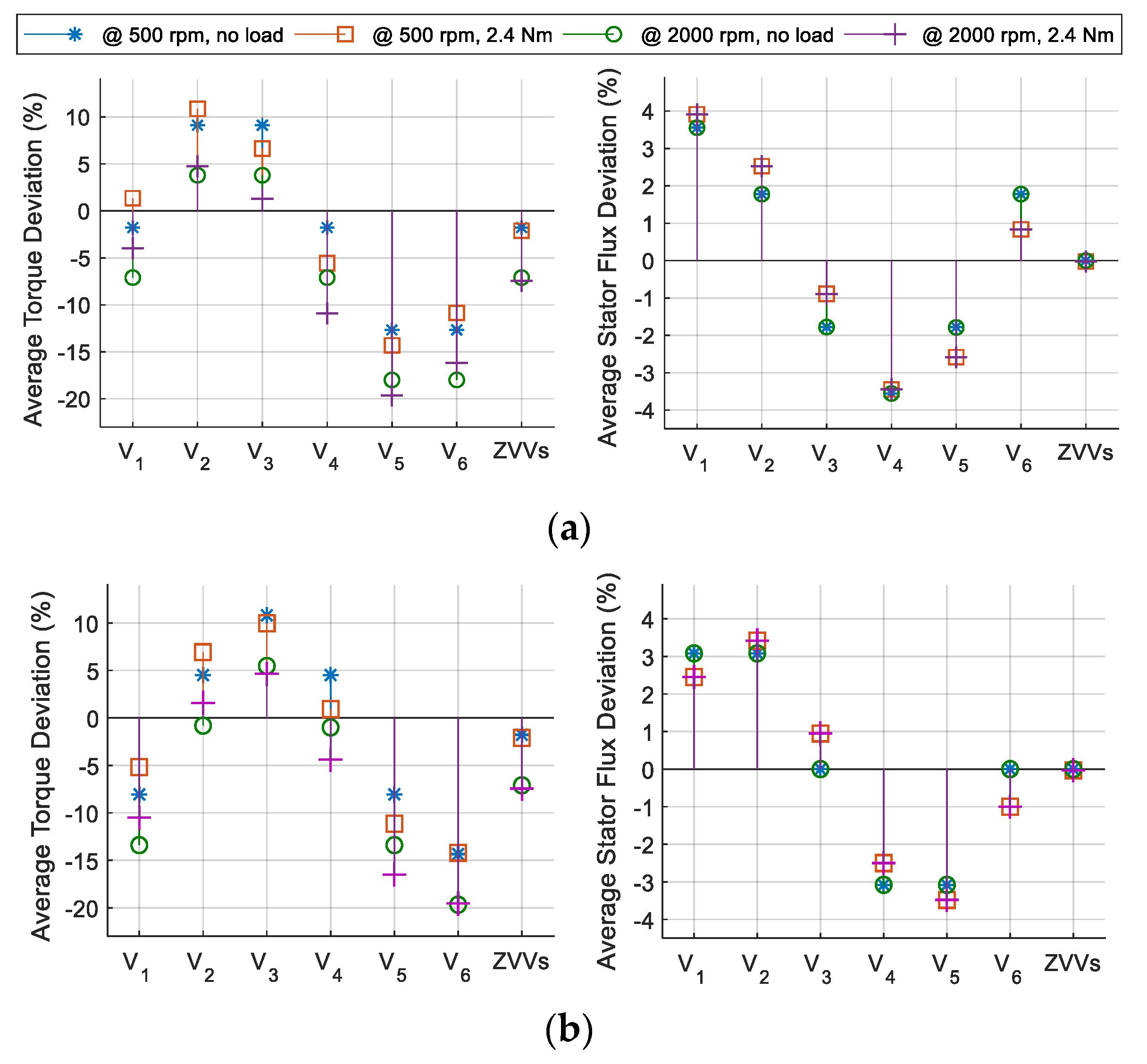
2.3. Analyzing the Voltage Selection in the Conventional ST

Because the selected voltage vector is applied for the whole control period in ST-DTC, the lower the torque and stator flux deviations produced by the selected voltage vector, the better the steady-state and the slower the dynamic response the system can achieve and vice versa [2]. Hence, analyzing the effect of each voltage vector on the torque and stator flux deviations during one sampling period was used in this work to assess the voltage selection strategy of each ST.
From (2) and (3), the torque and stator flux deviation rates can be written as [22]:
d T e d t = 3 p 2 L s ( Im ( V s α β ψ r α β ) R s L s Im ( ψ s α β ψ r α β ) ω r Re ( ψ s α β ψ r α β ) ) ,
d ψ s d t = 1 ψ s Re ( ψ s α β ( V s α β R s I s α β ) ) ,
where ω r = d θ r / d t is the electrical angular speed of the rotor.
The abovementioned equations reveal that the effect of the applied voltage vector on the torque and stator flux deviations varies according to the operating conditions. Thus, the average deviations of the torque and the stator flux within each sector, produced by each voltage vector, were calculated for the PMSM under test, with the parameters given in Appendix A, at different operating conditions. Figure 3 shows the resulting calculations when the stator flux vector was located at S1, as an example, with the traditional and modified sector boundaries. The machine operated at steady-state with a short sampling period (Ts = 25 μs) to allow the assumption that the deviation rates of the torque and the stator flux during this period were constants [16].
It can be observed in Figure 3a that V2 and V3 are the only available options to increase the torque in sector S1 under all operating conditions. Therefore, employing Vx+1 for the state “ K ψ   = 1, K T   = 1” and Vx+2 for the state “ K ψ   = −1, K T   = 1” is the optimal solution for BST, AST, and ZST. Moreover, both V1 and V6 can provide negative torque deviation and positive stator flux variation, but V6 is a better choice in this case because of the conflicting torque behavior caused by V1, especially at low-speed and high loading conditions. Thus, selecting Vx−1 for the state “ K ψ   = 1, K T   = −1” of BST, AST, and ZST is the best option.
Because ZVVs produce very low deviations in the stator flux (around −0.03%), they are acceptable to be used at the states where K T   = 0 in BST and MBST. However, they are more efficiently employed for the state “ K ψ   = −1, K T   = −1” in ZST because of their negative produced torque deviations. Moreover, utilizing ZVVs at this state, instead of Vx−2 in AST, can reduce the steady-state ripples, because ZVVs cause lower torque and stator flux deviations than those of V5 as shown in Figure 3a. For the same reason, this will impair the dynamic response of ZST when a torque decrease is demanded. In addition, during speed reversal, the torque deviation rate of ZVVs becomes positive as implied by the second and third terms of Equation (6); thus, selecting a ZVV when K T   = −1 to achieve this task in ZST will cause system instability. Instead, ZVV and V5 are superior choices to be employed during reverse rotation of the motor for the states “ K ψ   = 1, K T   = 1” and “ K ψ   = −1, K T   = −1”, respectively, in ZST.
With the modified sector boundaries, it can be noted from Figure 3b that all AVVs employed in MBST when x = 1, i.e., V2, V1, V4, and V5, provide lower torque deviations and higher stator flux deviations compared with V2, V6, V3, and V5, respectively, which are used with the traditional sector boundaries (see Figure 3a). As a result, MBST can provide lower torque ripple at low speed, and higher stator flux ripple than that of the BST. Additionally, both V4 and V2 fail to increase the torque, especially at high operating speed, which weakens the effectiveness of voltage vector selection based on the modified sector boundaries.
According to the aforementioned analysis, the voltage vectors are more efficiently selected in ZST for steady-state operation, while employing those of AST will be more suitable during system transients. However, the main drawback of ZST is that it does not allow reversing the rotation direction.

3. Proposed Flexible ST and Voltage Selection Strategy

From the aforementioned analysis, selecting ZVV at the state “ K ψ   = −1, K T   = −1” can be beneficial for the steady-state performance, but this will cause slow torque response when a reduction is commanded. Furthermore, the ZVV at this state cannot achieve speed reversal, as in case of ZST. To overcome these two issues, AVV (Vx−2) is the optimal choice to be applied. To keep the steady-state performance of ZST while rotation in the reverse direction, ZVV needs to be employed at the state “ K ψ   = 1, K T = 1” instead of Vx+1 because the torque deviation of the former becomes less positive. Therefore, for overall performance enhancement of ST-DTC technique, the voltage vector selection criteria need to be more flexible by considering additional factors besides the traditional factors, i.e., the system operating state and the direction of rotation.
Table 2 shows the proposed flexible switching table (FST). The voltage vectors at two states of this ST, ( K ψ   = 1, K T   = 1) and ( K ψ   = −1, K T   = −1), are flexibly selected depending on the system operating state and the direction of rotation. This is achievable using a simple voltage selection strategy whose flowchart is illustrated in Figure 4. As can be seen in the flowchart, the system operating state can be detected by the reference torque transition ( Δ T e r e f ( k ) = T e r e f ( k ) T e r e f ( k 1 ) ) to avoid the usage of torque sensor that will increase the system cost and complexity. If any change in the demanded torque is detected ( Δ T e r e f ( k )   ≠ 0), AVVs will be activated for all states of the ST to achieve fast torque response. This activation has to be kept until the torque error ( T e e r r ( k ) ) reaches a value within the hysteresis band of the torque controller ( | T e e r r ( k ) |   hT), and the direction of rotation becomes the same as that of the reference torque ( T e r e f ( k ) × ω r ≥ 0) to allow speed reversal if required. Thus, maintaining the AVVs activated is guaranteed using a “flag” that will reset only when either of the aforementioned conditions is not satisfied. On the other hand, as long as no torque transition is detected ( Δ T e r e f ( k )   = 0), which means that the system operates in steady-state mode, ZVVs will be activated at only one state based on the direction of rotation which can be detected by the position sensor. Following this strategy allows overcoming the drawbacks associated with ZST.
For further steady-state performance improvement, the switching frequency can be reduced by carrying out a trade-off between employing V0 or V7 at the kth sample when the ZVVs are activated in the proposed FST. This was fulfilled by checking the selected voltage vector at the previous sampling instant ( V i ( k 1 ) ); if it is V0, V1, V3 or V5, the ZVV “V0” will be employed, while V7 will follow the other voltage vectors to minimize the number of switching instances. In this way, the proposed ST is flexible because, unlike conventional STs, it does not have a fixed structure, but it takes changing forms according to the working condition of the DTC system and, hence, exploiting the benefits of employing both AVVs and ZVVs in the ST more efficiently. The effectiveness of the proposed FST and the voltage selection strategy will be confirmed by the experimental results in the next section.

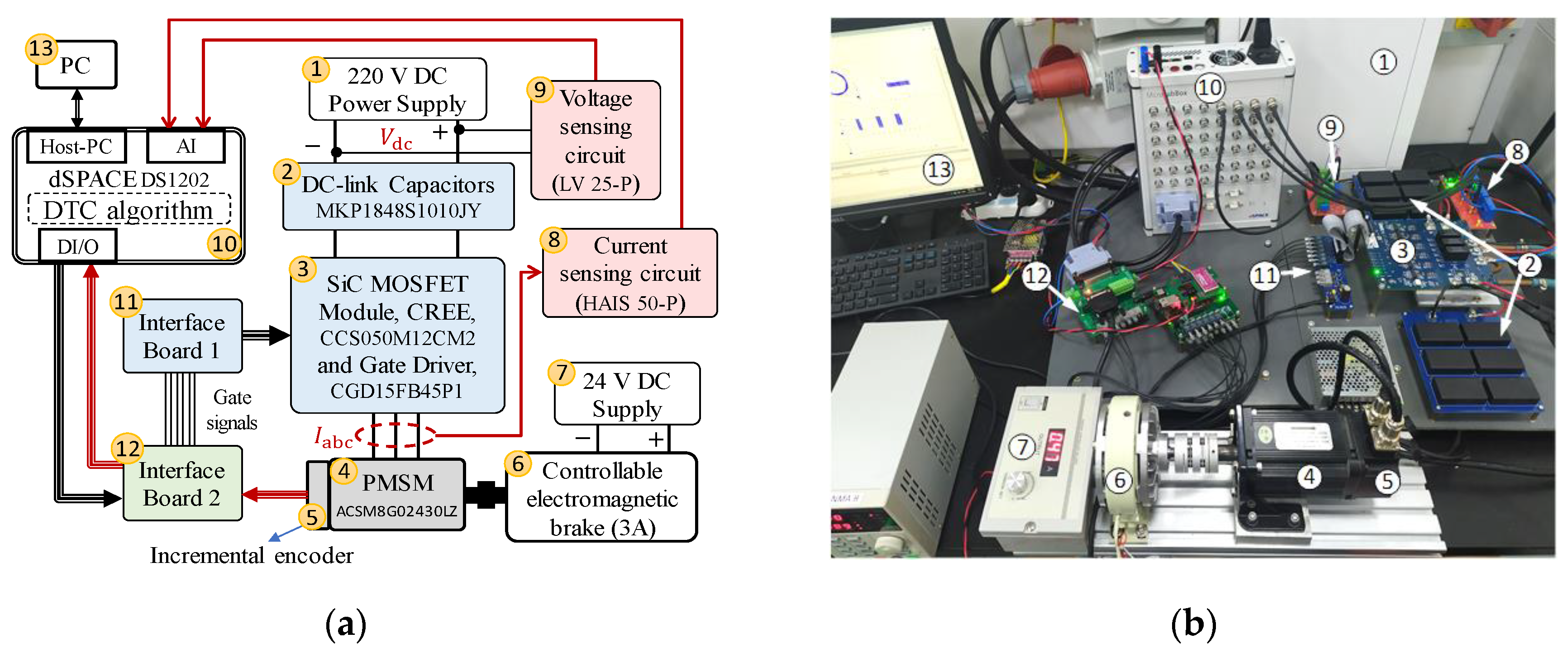
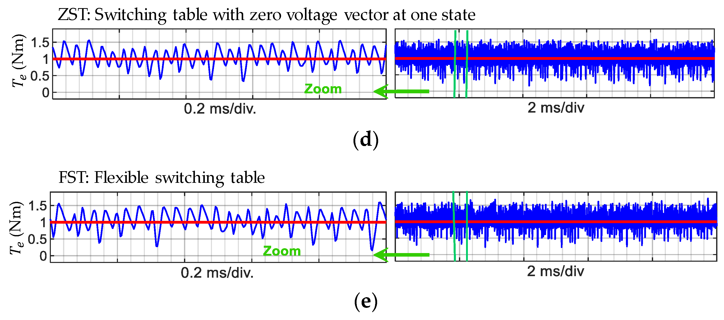
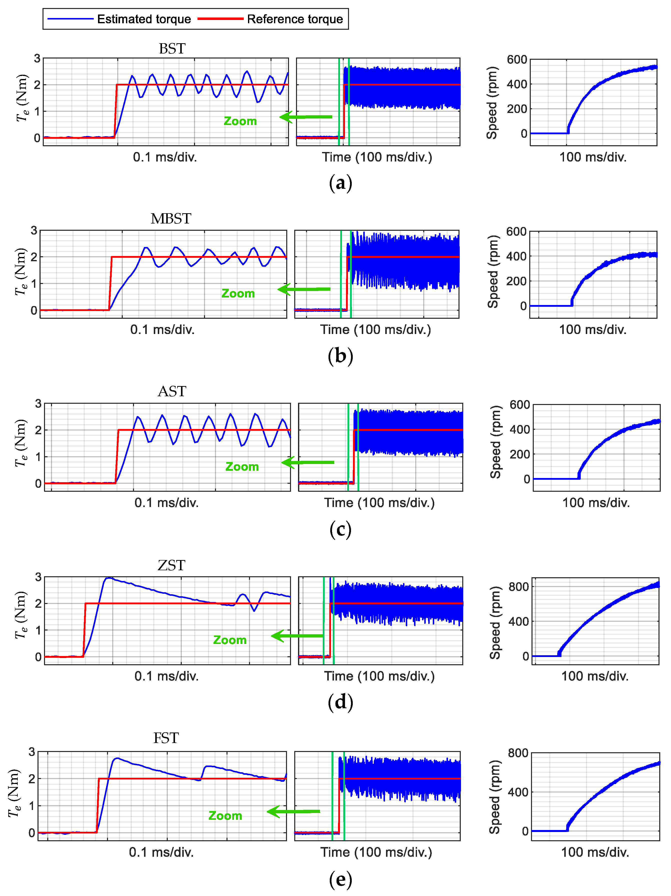
4. Experimental Results

Experimental verifications were carried out on a 0.75 kW PMSM (ACSM80G02430LZ) to validate the effectiveness of the proposed FST. Figure 5 illustrates the schematic diagram and the corresponding experimental setup for the PMSM drive system used in this work. The PMSM was fed by a 2L-VSI using the SiC MOSFET power module (CCS050M12CM2, CREE, North Carolina, USA) and its gate driver board (CGD15FB45P1). The DC-side of the inverter consisted of a 220 V DC power supply and 20*10 μF voltage stabilizing capacitors (MKP1848S1010JY, VISHAY, Pennsylvania, USA). The stator currents and the DC-side voltage were measured via HAIS 50-P and LV 25-P Hall sensors, respectively, produced by LEM (Geneva, Switzerland). The DTC scheme, shown in Figure 1, was simulated in MATLAB/Simulink (The MathWorks, Massachusetts, USA) and realized using the MicroLabBox (DS1202, dSPACE GmbH, Paderborn, Germany) rapid control-prototyping system which also can accomplish the sampling tasks of the measured voltage and currents; the rotor angular position and speed were obtained from an incremental encoder that had a resolution of 2500 pulses per revolution; the motor shaft was coupled to an electromagnetic brake fed from a 24 V variable DC-supply to control the load torque.
It should be noted that ψ s r e f was obtained from the demanded torque ( T e r e f ) based on the maximum torque per ampere principle using Equation (8) to increase the system efficiency [22], whereas the torque and stator flux estimations were fulfilled using (2) and (3) for simplicity.
ψ s r e f = ψ f 2 + ( 2 L s T e r e f 3 p ψ f ) 2
The effectiveness of the proposed FST was verified through comparative assessment with BST, MBST, AST, and ZST in terms of the steady-state and the dynamic performances provided by applying each ST in the DTC system, and collecting the experimental results under the same control parameters, given in Appendix A, as used in the analysis presented in Section 2. The experimental results were captured by ControlDesk software installed on a PC connected to the MicroLabBox, and then drawn using MATLAB.
First, the DTC steady-state performances provided by the conventional STs and proposed FST were compared under the same operating conditions. The reference torque was set to 1 Nm, and the load torque was adjusted using the electromagnetic brake until the speed reached the required value. Figure 6 and Figure 7 show the experimental waveforms of the electromagnetic torque and the stator flux locus, respectively, at 1000 rpm. Additionally, to consider the effect of speed variation on the steady-state performances, Table 3 gives quantitative comparison for all STs in terms of the torque ripple, the stator flux ripple, and the average switching frequency under three different speeds. The steady-state torque and flux ripples were calculated using (9), while the average switching frequency (fav) was obtained by averaging the total number of switching instances of the three legs of the inverter during a fixed period [2].
y r i p p l e = 1 m   k = 1 m ( y ( k ) y a v ) 2 ,
where y can be the torque or the stator flux amplitude, y ( k ) is the instantaneous value, y a v is the average value, and m is the number of samples.
From Figure 6 and Figure 7, it can be observed that the application of BST and AST gave almost an identical steady-state performance, and MBST generated lower torque ripple than them while its flux ripple was the highest. Both ZST and FST exhibited the lowest torque and stator flux ripples.
According to Table 3, when the machine ran at 500 or 1000 rpm, the application of MBST reduced the torque ripple compared with BST by 6% on average; however, the stator flux ripple increased by 29%. When the speed increased to 2000 rpm, the torque ripple associated with MBST became significantly higher than that of BST by 57%. By removing ZVVs from BST, as in case of AST, the torque and stator flux ripples increased by an average of 10% and 3%, respectively, under all operating speeds. On the other hand, utilizing ZVVs at one state in both ZST and FST achieved the highest torque and flux ripples reduction which were 32% and 12%, respectively, when compared to those of AST at 500 rpm. These torque and flux ripple reductions decreased to 12% and 7%, respectively, when the speed increased to 2000 rpm.
In addition to the better performance achieved by utilizing ZVVs at one ST state during steady-state operation, the average switching frequency was significantly reduced by the proposed voltage selection strategy that carries out a trade-off between employing V0 or V7 for every control sample as mentioned in Section 3. Compared with BST, MBST, AST, and ZST, the FST provided lower average switching frequency, at all operating speeds by an average of 42%, 37%, 40%, and 5%, respectively.
Apart from the steady-state performance experiments, the torque dynamic performances of the DTC system using the different STs were also tested and compared in Figure 8 and Figure 9. In this experiment, the load torque was set to 1.8 Nm and the reference torque was stepped up from 0 to 2 Nm to test the torque response during start-up. Then, it was stepped down from 2 to −2 Nm to confirm the torque response during speed reversal. The corresponding speed responses of the machine for these two scenarios are presented to the right of the torque response in both figures.
In Figure 8, it can be seen that there was insignificant differences between the torque rising times provided by BST, AST, ZST, and proposed FST, which was about 0.1 ms. However, it was higher in case of MBST (almost 0.2 ms), because the employed AVV at the state “ K ψ   = 1, K T   = 1” produced lower torque deviation with the modified sector boundaries than that with the traditional sector boundaries (see Figure 3).
When the reference torque decreased from 2 to −2 Nm, as shown in Figure 9, all the STs achieved almost the same torque falling time (0.2 ms) except ZST, which had a torque that took nearly 1 ms to reach the reference value. This was because the ZVV employed at the state “ K ψ   = −1, K T = −1” in ZST produced lower torque deviation than the AVV used in the other STs. Additionally, the DTC system that used ZST becomes unstable when the speed dropped to zero during speed reversal, as shown in the zone (10 ms/div.) of Figure 9d, because the torque deviation provided by ZVVs also reversed as mentioned in Section 2. Conversely, FST allows faster torque drop and smooth speed reversal as can be seen in Figure 9e, because its voltage selection strategy replaces ZVV with AVV during the dynamic state of the system. After speed reversal, ZVV is activated only at the state “ K ψ   = 1, K T   = 1” to achieve a steady-state performance similar to that before reversing the direction of rotation. This is confirmed in the zoomed zone (2 ms/div.) of Figure 9e.
The abovementioned results confirm the theoretical analysis presented in Section 2 and reveal that the proposed FST provides the lowest steady-state ripples in torque and stator flux as those achieved by ZST while reducing the average switching frequency and enhancing the torque decreasing response and system stability during speed reversal.

5. Conclusions

This article proposed a flexible ST with a structure, unlike the conventional STs, changes according to the system operating state to improve the overall performance of the DTC system of 2L-VSI PMSM while maintaining its ease of implementation. A simple yet effective strategy used to decide the voltage vectors arrangement in the FST which only requires information about the reference torque and the rotation direction. Compared to BST, MBST, and AST, the main features achieved by FST are summarized as follows: 1) reduction of torque and stator flux ripples by an average of 22% and 10%, respectively; 2) the average switching frequency was remarkably reduced by 31% on average. Although ZST provides steady-state performance similar to FST, the latter is more suitable for practical applications, as it allows speed reversal and gives better torque dynamic response.
It should be noted that, although the analysis and experiments in this paper were based on the traditional ST-DTC, the proposed FST can also be extended and used in other switching-table-based DTC approaches, such as the duty ratio modulation methods, for further performance improvement.

Author Contributions

All the authors gave their contribution to all the aspects of this work. A.N. formulated the voltage selection strategy of the proposed FST and developed the analytical results; A.N. and C.G. (Chunyang Gu) arranged the experimental setup and performed the tests; A.N. wrote the paper; S.B. and C.G. (Chunyang Gu) reviewed and edited the paper and together with C.G. (Chris Gerada) supervised all the work. All authors have read and agreed to the published version of the manuscript.

Acknowledgments

This research was supported by Zhejiang Natural Science Foundation under Grant LQ19E070002, Ningbo Science and Technology Bureau under Grant 2018A610146.

Conflicts of Interest

The authors declare no conflict of interest.

Nomenclature

Vsαβ, IsαβStator voltage (V) and current (A) vectors in stationary reference frame
ψsαβ, ψrαβStator and rotor flux vectors in stationary reference frame (Wb)
ψs, ψfStator and rotor (permanent magnet) flux amplitude (Wb)
θs, θrElectrical angular position of the stator and rotor flux vectors (degree)
TeElectromagnetic torque (Nm)
Rs, LsStator winding resistance (Ω) and inductance (H)
TsSampling period (s)
KT, KψDigital indicators of the torque and flux deviation directions
δElectrical load angle (degree)
kSampling index
x (subscript)Sector index
ref, 0 (superscript)Reference value and initial value
err (superscript)Error value
(superscript)Conjugate of a complex space vector
Sa, Sb, ScSwitching states of the inverter legs
div.Division
STSwitching table
DTCDirect torque control
PMSMPermanent magnet synchronous motor
CVCCurrent vector control
MPCModel predictive control
AVVActive voltage vector
ZVVZero voltage vector
2L-VSITwo-level voltage source inverter
BSTBasic switching table in Reference [19]
MBSTBasic switching table with modified sector boundaries in Reference [20]
ASTSwitching table with only active voltage vectors in Reference [18]
ZSTSwitching table with zero voltage vector at one state in Reference [21]
FSTFlexible switching table (proposed)
SiCSilicon carbide
MOSFETMetal-oxide-semiconductor field-effect transistor
DCDirect current
RMSRoot mean square

Appendix A

Table A1. PMSM and control parameters.
Machine ParametersValueControl ParametersValue
Stator resistance (Rs)0.901 ΩDC bus voltage (Vdc)220 V
Inductance (Ls)6.552 mHSampling frequency (fs)40 kHz
Number of pole pairs (p)4Torque hysteresis band (± h T )±2% of Trated
PM flux linkage ( ψ f )0.09427 WbFlux hysteresis band (± h ψ )±2% of ψ f
Rated current (Is)4.2 A (RMS)
Rated shaft output power0.75 kW
Rated speed3000 rpm
Rated torque (Trated)2.4 Nm
Inertia coefficient (J)1.2 kg·m2·10−4

References

  1. Abad, G. Power Electronics and Electric Drives for Traction Applications; Wiley: Chichester, UK, 2017; p. 630. [Google Scholar]
  2. Niu, F.; Wang, B.; Babel, A.S.; Li, K.; Strangas, E.G. Comparative Evaluation of Direct Torque Control Strategies for Permanent Magnet Synchronous Machines. IEEE Trans. Power Electron. 2016, 31, 1408–1424. [Google Scholar] [CrossRef]
  3. Wang, Z.; Chen, J.; Cheng, M.; Chau, K.T. Field-Oriented Control. and Direct Torque Control. for Paralleled VSIs Fed PMSM Drives With Variable Switching Frequencies. IEEE Trans. Power Electron. 2016, 31, 2417–2428. [Google Scholar] [CrossRef]
  4. Liu, C.; Luo, Y. Overview of advanced control strategies for electric machines. Chin. J. Electr. Eng. 2017, 3, 53–61. [Google Scholar]
  5. Ban, F.; Lian, G.; Zhang, J.; Chen, B.; Gu, G. Study on a Novel Predictive Torque Control. Strategy Based on the Finite Control. Set for PMSM. IEEE Trans. Appl. Supercond. 2019, 29, 1–6. [Google Scholar] [CrossRef]
  6. Wang, S.; Li, C.; Che, C.; Xu, D. Direct Torque Control. for 2L-VSI PMSM Using Switching Instant Table. IEEE Trans. Ind. Electron. 2018, 65, 9410–9420. [Google Scholar] [CrossRef]
  7. Rahman, M.F.; Zhong, L.; Haque, M.E.; Rahman, M.A. A direct torque-controlled interior permanent-magnet synchronous motor drive without a speed sensor. IEEE Trans. Energy Convers. 2003, 18, 17–22. [Google Scholar] [CrossRef]
  8. Xia, C.; Wang, S.; Gu, X.; Yan, Y.; Shi, T. Direct Torque Control. for VSI-PMSM Using Vector Evaluation Factor Table. IEEE Trans. Ind. Electron. 2016, 63, 4571–4583. [Google Scholar] [CrossRef]
  9. Ren, Y.; Zhu, Z.Q. Reduction of Both Harmonic Current and Torque Ripple for Dual Three-Phase Permanent-Magnet Synchronous Machine Using Modified Switching-Table-Based Direct Torque Control. IEEE Trans. Ind. Electron. 2015, 62, 6671–6683. [Google Scholar] [CrossRef]
  10. Ren, Y.; Zhu, Z.Q.; Liu, J. Direct Torque Control of Permanent-Magnet Synchronous Machine Drives With a Simple Duty Ratio Regulator. IEEE Trans. Ind. Electron. 2014, 61, 5249–5258. [Google Scholar] [CrossRef]
  11. Liu, Q.; Hameyer, K. Torque Ripple Minimization for Direct Torque Control of PMSM With Modified FCSMPC. IEEE Trans. Ind. Appl. 2016, 52, 4855–4864. [Google Scholar] [CrossRef]
  12. Weijie, L.; Dongliang, L.; Qiuxuan, W.; Lili, C.; Xiaodan, Z. A novel deadbeat-direct torque and flux control of IPMSM with parameter identification. In Proceedings of the 2016 18th European Conference on Power Electronics and Applications (EPE’16 ECCE Europe), Karlsruhe, Germany, 5–9 September 2016. [Google Scholar]
  13. Zanma, T.; Kawasaki, M.; Liu, K.; Hagino, M.; Imura, A. Model Predictive Direct Torque Control for PMSM with Discrete Voltage Vectors. IEEJ J. Ind. Appl. 2014, 3, 121–130. [Google Scholar] [CrossRef] [Green Version]
  14. Sandre-Hernandez, O.; Rangel-Magdaleno, J.; Morales-Caporal, R. A Comparison on Finite-Set Model Predictive Torque Control Schemes for PMSMs. IEEE Trans. Power Electron. 2018, 33, 8838–8847. [Google Scholar] [CrossRef]
  15. Rahideh, A.; Rahideh, A.; Karimi, M.; Shakeri, A.; Azadi, M. High Performance Direct Torque Control of a PMSM using Fuzzy Logic and Genetic Algorithm. In Proceedings of the 2007 IEEE International Electric Machines & Drives Conference, Antalya, Turkey, 3–5 May 2007. [Google Scholar]
  16. Niu, F.; Li, K.; Wang, Y. Direct Torque Control for Permanent-Magnet Synchronous Machines Based on Duty Ratio Modulation. IEEE Trans. Ind. Electron. 2015, 62, 6160–6170. [Google Scholar] [CrossRef]
  17. Takahashi, I.; Noguchi, T. A New Quick-Response and High-Efficiency Control Strategy of an Induction Motor. IEEE Trans. Ind. Appl. 1986, IA-22, 820–827. [Google Scholar] [CrossRef]
  18. Zhong, L.; Rahman, M.F.; Hu, W.Y.; Lim, K.W. Analysis of direct torque control in permanent magnet synchronous motor drives. IEEE Trans. Power Electron. 1997, 12, 528–536. [Google Scholar] [CrossRef]
  19. Yuwen, H.; Cun, T.; Yikang, G.; Zhiqing, Y.; Tang, L.X.; Rahman, M.F. In-depth research on direct torque control of permanent magnet synchronous motor. In Proceedings of the IEEE 2002 28th Annual Conference of the Industrial Electronics Society (IECON 02), Sevilla, Spain, 5–8 November 2002. [Google Scholar]
  20. Toufouti, R.; Meziane, S.; Benalla, H. Direct Torque Control Strategy of Induction Motors. J. Acta Electrotech. Et Inform. 2007, 7, 22–28. [Google Scholar]
  21. Yaohua, L.; Gerling, D.; Weiguo, L. A novel switching table using zero voltage vectors for direct torque control in permanent magnet synchronous motor. In Proceedings of the 2008 18th International Conference on Electrical Machines, Vilamoura, Portugal, 6–9 September 2008. [Google Scholar]
  22. Zhang, Y.; Zhu, J. A Novel Duty Cycle Control Strategy to Reduce Both Torque and Flux Ripples for DTC of Permanent Magnet Synchronous Motor Drives With Switching Frequency Reduction. IEEE Trans. Power Electron. 2011, 26, 3055–3067. [Google Scholar] [CrossRef]
  23. Shinohara, A.; Inoue, Y.; Morimoto, S.; Sanada, M. Comparison of stator flux linkage estimators for PWM-based direct torque controlled PMSM drives. In Proceedings of the 2015 IEEE 11th International Conference on Power Electronics and Drive Systems, Sydney, Australia, 9–12 June 2015. [Google Scholar]
Figure 1. Block diagram of the switching table (ST)-based direct torque control (DTC) technique for permanent magnet synchronous motor (PMSM).
Energies 13 01907 g001
Figure 2. Basic concept of DTC.
Energies 13 01907 g002
Figure 3. Average torque and stator flux deviations in percentage of their rated values, produced by each voltage vector at different operating conditions, sampling period of 25 μs, and x = 1 with (a) the traditional sector boundaries ( θ s [−30°, 30°]) and (b) the modified boundaries ( θ s [0°, 60°]).
Energies 13 01907 g003
Figure 4. Flowchart of voltage vector selection strategy for the proposed FST.
Energies 13 01907 g004
Figure 5. PMSM-based drive system: (a) Schematic diagram; (b) Experimental setup.
Energies 13 01907 g005
Figure 6. Experimental waveforms of the steady-state torque response at 1000 rpm and 1 Nm load: (a) BST; (b) MBST; (c) AST; (d) ZST; (e) FST. (Reference torque: red, Estimated torque: blue).
Energies 13 01907 g006aEnergies 13 01907 g006b
Figure 7. Experimental results of the steady-state response of stator flux at 1000 rpm and 1 Nm load: (a) BST; (b) MBST; (c) AST; (d) ZST; (e) FST.
Energies 13 01907 g007
Figure 8. The torque dynamic response and the corresponding speed response for step change in the reference torque from 0 to 2 Nm for the different STs: (a) BST; (b) MBST; (c) AST; (d) ZST; and (e) FST.
Energies 13 01907 g008
Figure 9. The torque dynamic response and the corresponding speed response for step change in the reference torque from 2 to −2 Nm for the different STs: (a) BST; (b) MBST; (c) AST; (d) ZST; and (e) FST.
Energies 13 01907 g009
Table 1. Voltage selection of the conventional STs.
K ψ K T Voltage Selection
BSTMBSTASTZST
11Vx + 1Vx + 1Vx + 1Vx + 1
0ZVVZVV--
−1Vx − 1VxVx − 1Vx − 1
−11Vx + 2Vx + 3Vx + 2Vx + 2
0ZVVZVV--
−1Vx − 2Vx − 2Vx − 2ZVV
Table 2. Proposed flexible switching table (FST).
K ψ K T Voltage Selection
11Vx + 1
ZVV
−1Vx − 1
−11Vx + 2
−1Vx − 2
ZVV
Table 3. Quantitative comparison of the STs under different operating speeds.
IndexSpeed (rpm)Switching Tables
BSTMBSTASTZSTFST
T r i p p l e   (Nm)5000.2720.2550.3070.2090.208
10000.2790.2640.3050.2440.246
20000.2740.4310.2990.2630.263
ψ r i p p l e (mWb)5003.6724.8483.7143.2513.252
10003.7154.7043.8283.3113.311
20003.7944.5623.9753.6823.682
fav (kHz)50010.279.089.854.584.31
10009.498.449.205.965.73
20008.618.158.436.426.13

