Article

An Off-Board Multi-Functional Electric Vehicle Charging Station for Smart Homes: Analysis and Experimental Validation

Department of Industrial Electronics, University of Minho;Campus de Azurem, 4800-058 Guimaraes, Portugal
*
Author to whom correspondence should be addressed.
Energies 2020, 13(8), 1864; https://doi.org/10.3390/en13081864
Submission received: 18 March 2020 / Revised: 10 April 2020 / Accepted: 10 April 2020 / Published: 11 April 2020

Abstract

:
This paper presents the analysis and experimental validation of a single-phase off-board multi-functional electric vehicle (EV) charging station (MF-EVCS), which has a single ac interface and two dc interfaces. As innovative aspects, the proposed MF-EVCS handles the interface of the ac power grid, the dc interface of a renewable energy source (RES), as well as the dc interface of an EV to perform dc charging or discharging of the batteries (in off-board grid-to-vehicle (G2V) or vehicle-to-grid (V2G) modes). Considering the power grid, the individual operation modes of the RES and the EV interfaces can be considered. Moreover, a combination of these modes is also possible. Besides, the MF-EVCS has as key innovative aspect the possibility of operating as an active power filter (APF), supporting the operation with reactive power and/or selected current harmonics. This possibility can be associated with any of the previous mentioned modes. These new features are framed in two distinct scenarios: in a smart home, where the ac-side current can be determined as a function of the other electrical appliances; in a smart grid, where the ac-side current can be determined as a requisite of the power grid. The proposed power theory, as well as the current control strategies for both ac-side and dc-side of the MF-EVCS, are presented in the paper for all the possible operation scenarios. A laboratory prototype was developed to validate the proposed MF-EVCS and the experimental results confirm its suitability for smart homes.

Graphical Abstract

1. Introduction

New paradigms are emerging for the future of power systems, including the connection of distributed renewable energy sources (RES), storage systems and the broad dissemination of electric vehicles (EV) [1]. In this context, along the last decades, RES and EV and have been identified as key enablers for sustainable smart grids, also contributing to the appearance of emerging technologies regarding the power grid interface [2]. Also the issues of power quality are very relevant in the context of smart grids, as well as in the context of smart homes [3,4,5]. Surveys about vehicle electrification are presented in [6,7,8], the impact of the EV operation regarding the distribution system is analyzed in [9], future trends of propulsion technologies are offered in [10] and a future outlook of EV penetration is presented in [11]. However, as it has been identified, the EV is not only recognized in the context of a more sustainable mobility, but also in terms of supporting the power grid, offering new opportunities for the energy market and boosting energy management and efficiency, representing crucial factors in smart grids. With this perspective, challenges and opportunities in terms of operation modes for supporting ancillary services are scrutinized in [12,13,14,15]. Besides, the interaction of the EV in terms of power quality is dissected in [16,17]. Contextualizing the EV interaction with the power grid, three main challenges are correlated: (a) in a short period of time, a significant amount of power is needed to carry out the EV charging; (b) the EV is differentiated as being a flexible element in the power grid, being introduced randomly into the power grid; (c) the EV can operate as a load (receiving energy) or as a source (providing energy) from the power grid point of view. It is in this context, that the strategic introduction of RES assumes a preponderant role, contributing to minimize the energy requirements of the power grid, since the energy necessary for the EV can be supplied directly by the RES [18,19,20,21]. This new strategic vision for the power grids is seen as fundamental for the development of sustainable smart grids, ensuring the optimization of energy management procedures [22]. Considering this collaborative approach between EV and RES, several strategies can be adopted, both in terms of power electronics structures and in terms of control algorithms. A study about the harmonious support of the EV with RES in the perspective of smart grids is offered in [23]. An optimal strategy, from the point of view of control algorithms, to incorporate EVs in scenarios of microgrids contemplating uncertainties of RES power production and EV charging stations is studied in [24]. Summarizing, the cooperation between EVs and RES is essential but, taking into account the uncertainties associated with each technology, the use of cooperative algorithms is essential. In addition, intelligent charging strategies for EVs are fundamental (i.e., besides the definition of schedules for charging/discharging), providing also an improvement in the performance of the power grid, as demonstrated in [25]. In this context, a matched EV charging from the perspective of diminishing power losses in power grid operation is presented in [26] and an unified energy management from the perspective of the power grid, combining the EV operation with RES, is described in [27]. However, despite the relevance of these solutions at the level of control algorithms in a panorama of smart grids, analyzing in detail, it can easily be seen that at the level of power electronics, there is a major disadvantage: each technology has its own system, i.e., two separate power structures are considered, namely the EV charging system and the RES power inverter. Thus, when it is intended to charge the EV with energy from RES, the power grid is obligatorily used, operating as an intermediary and causing power losses. This is the main disadvantage of the traditional systems and it is in this context that the main research question arises: is it possible to develop a unified system capable of handling the interface of EV and RES with the power grid and, at the same time, capable to operate as an active power filter? As a contribution to answer this question, this paper proposes a multi-functional EV charging station (MF-EVCS) for smart homes, offering the possibility of integrating an EV and a RES with the power grid, using only one ac-side interface and two dc-side interfaces operating independently, but sharing a common dc-link interface. Furthermore, the MF-EVCS has as key advanced feature: the option of operating as an active power filter (APF), supporting the operation with reactive power and/or selected current harmonics. In view of this observation, it is undeniably verified that the requirements for power stages are reduced, since only three conversion stages are present (contrarily to the common approach, in which four stages are mandatory). Additionally, it can also be recognized that, with the proposed MF-EVCS, a maximum of two power stages are needed for the interface between EV and RES, contrarily to what happens with the traditional system, where, e.g., to transfer energy from RES to EV, four power stages are necessary (since it is mandatory to use the power grid). These innovative aspects contribute directly to support the answer to the research question.
The opportunity of using a MF-EVCS is in itself a major contribution for smart grid development, where the design of systems for optimizing energy efficiency are, of course, vital. Analogous structures can be found in [28] and [29], nevertheless simply mentioned in an analysis dedicated to the energy exchange between the technologies. In [30] a somewhat similar concept is offered, in which an EVCS, based on an electronic transformer, permits the RES interface. An off-board EV charging station, also permitting compensation of power quality problems, is presented in [31], but without the RES interface. An advanced off-board EV home charging station contextualized with smart homes is proposed in [32], but also without the RES interface. Based on the various mentioned aspects and the state of the art, as the main contributions of this paper, the following can be highlighted: (a) Grid-to-vehicle operation mode (G2V), where the EV is charged with energy provided exclusively from the power grid; (b) vehicle-to-grid operation mode (V2G), where the EV delivers part of the stored energy to the power grid, as a support of ancillary services; (c) RES-to-grid operation mode (R2G), where the energy produced by the RES (e.g., solar photovoltaic panels in this case) is injected into the power grid; (d) RES-to-EV operation mode (R2V), where the energy produced by the RES is used to charge the EV; (e) R2G and V2G operation mode (when both the RES and the EV are injecting energy into the power grid); (f) R2V and R2G operation mode (when the power from RES is enough to charge the EV and to inject into the power grid); (g) R2V and G2V operation mode (when the power to charge the EV is provided by the RES and by the power grid); (h) In the context of a smart home, a dedicated algorithm allows to control the front-end converter in order to compensate power quality problems caused by the electrical appliances (smart home), regardless of the operation mode of the dc interfaces (EV and RES); (i) In a smart grid context, it is possible to control the front-end converter to help compensating power quality problems, but from the point of view of the power grid (e.g., producing selected current harmonics), also independently of the operation mode of the dc interfaces; (j) A laboratory prototype was developed to validate the proposed MF-EVCS, where experimental results were obtained for the aforementioned operation modes.
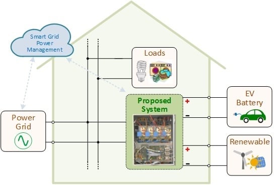
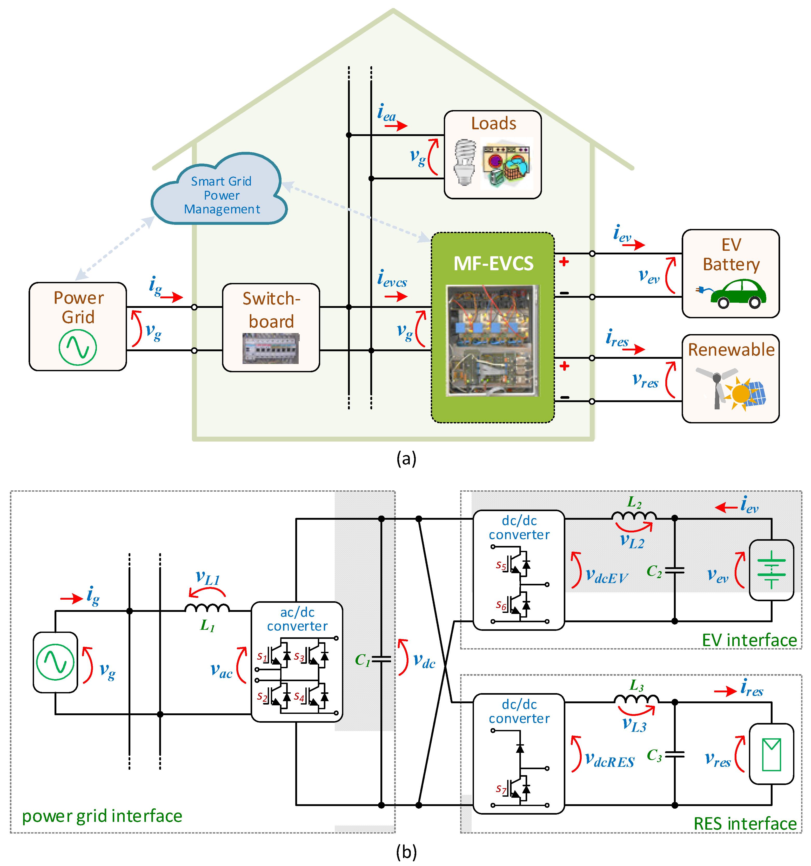
Figure 1a shows the introduction of the MF-EVCS in the context of a smart home and smart grid, while Figure 1b shows in detail its internal constitution regarding the converters. The proposed power theory and the current control schemes for the MF-EVCS are presented in Section 2. The details of the developed laboratory prototype are introduced in Section 3, while the experimental validation of the main distinct operation modes is presented in Section 4. A discussion about the different operation modes, and the relations among them, is presented in Section 5. The main conclusions and future perspectives are presented in Section 6.

2. MF-EVCS: Control Algorithm

The MF-EVCS control algorithm is performed according to the attained variables at the ac-side (power grid interface) and both dc-sides (EV and RES interfaces). Regarding the MF-EVCS in the ac-side, both the voltage and the current are measured. Additionally, since it can operate as an APF framed by the smart home (i.e., for compensating power quality issues, such as low power factor and current harmonics caused by nonlinear electrical appliances), it is also necessary to measure the total current in the smart home. Besides, aiming to achieve a collaborative approach with the smart grid, communication with a cloud-based energy management system is also fundamental, permitting users to define set-points of operation for the MF-EVCS when it is requested to the smart home the support of reactive power or the collaborative participation in selective harmonic compensation. In these cases, two approaches can be considered for the MF-EVCS operation: (a) It receives the requests and operates in collaboration according to its availability, i.e., it continues its operation framed by the smart home and collaborates with the smart grid only if it is not operating at the nominal power; (b) It receives the requests and adjusts its operation framed by the smart home (e.g., reducing the EV charging/discharging rating) to support the collaboration with the smart grid. These two possibilities are valid for the MF-EVCS, however, the detailed analysis about such controllability (e.g., the parameters of the communication channel or the priorities) is out of the scope of this paper. Instead, it is an objective of this paper to demonstrate that the MF-EVCS is prepared to deal with the operation in these two scenarios, as observed in the experimental validation.
Regarding the MF-EVCS operation in terms of active power, the presence or absence of the EV, as well as the energy production from RES, are differentiating factors. Independently of the amount of operating power of the EV charging/discharging operation and the energy production from RES, the active power in the ac-side (considering sinusoidal grid voltage and current, and unitary power factor) of the MF-EVCS is defined by:
P E V C S = V A C   I E V C S  
where VAC and IEVCS correspond to the ac-side rms values of voltage and current, respectively. The voltage VAC is imposed by the power grid, while the current IEVCS is imposed by the MF-EVCS and it is controlled by the front-end converter (full-bridge ac/dc) converter. The rms value of the ac-side current (IEVCS) varies according to the operating power in the dc-side (EV and RES) and the phase-angle in relation to the ac-side voltage depends whether the EV operation is in charging mode (grid-to-vehicle, G2V) or in discharging mode (vehicle-to-grid, V2G). In order to guarantee that the dc-link voltage is properly controlled for the MF-EVCS operation, an amount of power must be absorbed from the power grid, independently of the EV operation or the RES production. The power on the dc-side (pdc-side) corresponds to:
p d c s i d e = p d c + i e v   v e v + i r e s   v r e s   ,
where iev and vev are the dc-side current and voltage of the EV interface, while ires and vres are the dc-side current and voltage of the RES interface. From (1), it is possible to verify that the rms value of the ac-side current is the variable that is controlled on the ac-side; therefore, rearranging (2) in function of such current and neglecting the losses, results in:
  I E V C S = P D C s i d e V A C   .
Based on Equation (3) it is possible to define a reference current for the ac-side current that is function of the MF-EVCS operating power (i.e., the EV and RES operating power). However, by analyzing (3) in more detail, two drawbacks are clearly identified: (a) The natural oscillation presented in the dc-link voltage (resultant from pdc) is reflected in the ac-side current; (b) The waveform of the ac-side voltage influences the waveform of the ac-side current. Fortunately, these two drawbacks can be solved by: (a) Implementing a low-pass filter in the dc-link voltage, permitting to obtain its average value to be used in the control algorithm; as a result, the dc-link voltage will oscillate, but this will not reflected in the reference of the ac-side current; (b) Implementing a phase-locked loop (PLL) in the ac-side voltage, permitting to obtain a purely sinusoidal waveform (vgPLLs), which is used in the control algorithm for establishing the reference of the ac-side current (therefore, synchronized only with the fundamental component). By implementing these two strategies, the MF-EVCS is prepared to deal with controlled active power, but to operate also with controlled reactive power, a reference in quadrature is mandatory. For such purpose, a proper PLL must be considered to obtain a signal in quadrature with the ac-side voltage (vgPLLc). Taking into consideration these two digital implementations, Equation (3) can be rewritten in terms of instantaneous values as:
i e v c s = 1 V G 2 ( p d c ¯ + i e v   v e v + i r e s   v r e s )   v g P L L s   .
From Equation (4), it is possible to conclude that the ac-side current (ievcs) is sinusoidal and it is defined in accordance with the EV and RES operation. Moreover, when the EV battery is in the charging process (G2V), the value of iev is positive and, consequently, ievcs is in phase with the ac-side voltage. On the other hand, when the EV battery is in the discharging process (V2G), the value of iev is negative and, consequently, ievcs is in phase opposition with the ac-side voltage. As the operation with reactive power is a characteristic of the MF-EVCS, a signal in quadrature with the fundamental component of the grid voltage must be included in Equation (4), resulting in:
i e v c s = 1 V G 2 ( ( p d c ¯ + i e v   v e v + i r e s   v r e s )   v g P L L s + Q * v g P L L c )   .
By analyzing Equation (5), it is possible to identify a variable Q*, which corresponds to the reference of reactive power for the operation of the MF-EVCS. When Q* is equal to zero, the reference of current for the ac-side is sinusoidal and in phase (or phase opposition, depending on the signal of iev) with the voltage, while when 
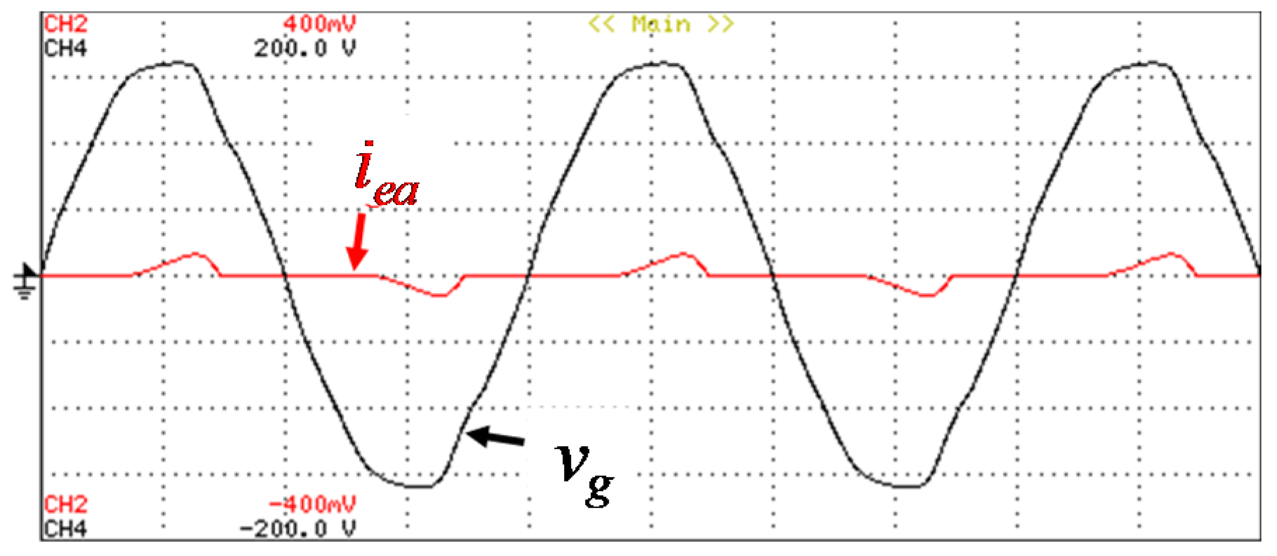
Q* is different from zero, the reference current is also sinusoidal, but with a non-zero phase angle in relation to the voltage. Summarizing, from Equation (5), it is possible to establish the reference for the ac-side current in order to the MF-EVCS operate with active and reactive power, where the active power is function of the EV (charging or discharging) and function of the RES production, while the reactive power is established by the requirements of the power grid. It is imperative to highlight that the reactive power operation does not jeopardize the EV charging or discharging operation or the power production from RES, since for the reactive power operation is only required the use of the ac/dc front-end converter. Nevertheless, the possibility of the MF-EVCS operation for compensating current harmonics is also an important feature that must be contemplated in the control. Therefore, Equation (5) must be rewritten in order to contemplate such possibility. As the objective is to compensate current harmonics, it is indispensable to identify the instantaneous value of the total current in the smart home, i.e., the current consumed by the electrical appliances besides the MF-EVCS. In order to do that, a simple, however powerful method, was adopted to define the reference current for the ac-side of the MF-EVCS, which consists on determining the fundamental component of the consumed current (electrical appliances) from the average value of the active power consumed by the electrical appliances. As a result, the harmonic compensating current (iah) is determined based on:
i a h = ( 1 V G 2   P ¯ E A   v g P L L s ) i e a   ,
which is function of the average value of the active power (PEA) and of the instantaneous value of the current consumed by the electrical appliances (iea). Moreover, as it can be verified, the harmonic compensation current (iah) is also dependent on the square of the rms value of the ac-side voltage, as well as the instantaneous value of the fundamental component of such voltage. Combining Equations (5) and (6) results in the final equation defined by:
i e v c s = 1 V G 2 ( ( p d c ¯ + i e v   v e v + i r e s   v r e s + P ¯ E A )   v g P L L s + Q * v g P L L c ) i e a   .
Equation (7) permits to define the reference current for the ac-side of the MF-EVCS independently of the operation mode, i.e., it can be used for the individual operation with active power, reactive power, harmonic compensation or for a combination of these modes. Taking into account a digital implementation, Equation (7) is programed during each sampling period [k, k+1] as:
i e v c s [ k ] = 1 V G [ k ] 2 ( ( p d c [ k ] + i e v [ k ] v e v [ k ] + P ¯ E A [ k ] )   v g P L L s [ k ] + Q * [ k ]   v g P L L c [ k ] ) i e a [ k ]   ,
where the average value of the active power consumed by the electrical appliances (PEA) is digitally implemented based on:
P ¯ E A = k = 1 f s f g f g i e a [ k ]   v g [ k ] f s   ,
where the values of fg and fs correspond, respectively, to the frequency of the ac-side voltage and to the sampling frequency of the digital control. Besides, it can be verified that the reference current defined in Equation (8) is also dependent on the digital implementation of the squared rms value of the ac-side voltage, which is determined according to:
V G [ k ] 2 = k = 1 f s f g f g v g [ k ] 2 f s   .
Based on Equation (8), it is possible to define all the operation modes of the MF-EVCS when operating in the context of a smart home. However, in the context of a smart grid, besides the operation with reactive power, the MF-EVCS also allows one to produce selected harmonics according to the requirements of the smart grid. As example, from the point of view of the smart grid, a set of smart homes, each one with a MF-EVCS, can be individually controlled to produce a selected harmonic, e.g., the smart home #1 produces a third current harmonic with a specific harmonic (with an amplitude and phase) and the smart home #2 produces a fifth harmonic with a specific harmonic (with an amplitude and phase). Therefore, the final control equation must also contemplate such possibility, according to:
i e v c s [ k ] = 1 V G [ k ] 2 ( ( p d c [ k ] + i e v [ k ] v e v [ k ] + P ¯ E A [ k ] )   v g P L L s [ k ] + Q * [ k ]   v g P L L c [ k ] ) i e a [ k ] + H i h [ k ] ,
where H corresponds to the amplitude of the current harmonic to be produced and ih[k] corresponds to the current harmonic (i.e., with the desired frequency of such harmonic, obtained from a PLL). As previously mentioned, Equation (8) permits to define the reference current for the ac-side of the MF-EVCS, based on the EV and RES operation, but it is necessary an additional control strategy to define the state of each switching device during each sampling period [k, k+1]. Therefore, a linear current control strategy was considered, which is defined based on the analysis of the connection of the front-end converter with the power grid. By analyzing the ac-side voltage and the ac-side current, as well as the voltage in the passive filter and the voltage of the converter vac (which is dependent on the assumed state of each switching device), it can be established the following relation:
v a c [ k ] = L 1 f s   ( i e v c s [ k ] i e v c s * [ k ] ) + v g [ k ]   ,
From Equation (12), it is possible to identify that the voltage of the converter (vac) is the variable that must be controlled in order to define the ac-side current. As previously mentioned, the waveform of the ac-side current is dependent on the reference current and it is not affected by the control Equation (12), since it is only considered to guarantee that the converter synthesizes a voltage (vac) that results in an ac-side current that follows its reference. The voltage (vac) is a function of the other variables, and therefore, it is established during each sampling period [k, k+1]. After establishing this voltage, it is then compared with a triangular carrier, whose fixed frequency is half of the switching frequency. From the comparison results the pulse-width modulation (PWM) gate-pulse patterns for the switching devices. The reference for the ac-side current established by Equation (8) during the sampling period [k, k+1] is used in Equation (11).
Regarding the dc-side, the EV interface is controlled by current, whose reference is established by: (a) The battery management system during the charging process; (b) The smart grid during the discharging process. Therefore, the establishment of the reference current is out of the scope of this paper. The MF-EVCS is responsible for controlling the operation of the dc-side in order to guarantee that such reference current is reached, both during the charging (G2V) and discharging (V2G). In order to accomplish with the charging process (G2V), a control equation is defined, also for the sampling period [k, k+1], in accordance with the instantaneous values of the EV battery voltage (vev) and current (iev). By analyzing the voltages and currents on the dc-side corresponding to the EV interface, it is established the following relation:
v d c E V [ k ] = L 2 f s   ( i e v [ k ] i e v * [ k ] ) + v e v [ k ]   ,
where it is possible to identify that the voltage vdcEV corresponds to the voltage that is produced by the MF-EVCS on the dc-side interface correspondent to the EV. The voltage vdcEV is compared with a triangular carrier, also with half of the sampling frequency, in order to define the gate-pulse patterns for the switching device s1 (Figure 1). Similarly, during the discharging process (V2G), a control equation is also defined and also for the sampling period [k, k+1]. In this case, it is established the following relation:
v d c E V [ k ] = L 2 f s   ( i e v [ k ] i e v * [ k ] ) v e v [ k ]   ,
The voltage vdcEV also corresponds to the voltage that is produced by the MF-EVCS on the dc-side interface correspondent to the EV and it is compared with the same triangular carrier in order to define the gate-pulse patterns for the switching device s2. Regarding the dc-side in terms of the RES interface, a control law is also established based on the voltage and currents of such interface. The reference current is established based on a maximum power point tracking algorithm. The control is established based on:
v d c R E S [ k ] = L 2 f s   ( i r e s [ k ] i r e s * [ k ] ) v r e s [ k ]   ,

3. MF-EVCS: Developed Prototype

A real-scale laboratory prototype was developed with the purpose of validating the different operation modes of the MF-EVCS, as described in the previous sections. Figure 2 shows the laboratory workbench, where it is highlighted the MF-EVCS. The experimental results were acquired with a DL708 digital oscilloscope (Yokogawa, Vila Nova de Gaia, Portugal) maintaining a sampling frequency of 1 ksps. For the switching devices, four SK75GB066IGBT modules from Semikron (Nurnberg, Germany) were considered. In order to control such IGBT modules, four dedicated model SKHI22AH4 gate-drivers, also from Semikron, were considered. For the dc-link, a parallel association of fifty capacitors was considered, each one with a nominal capacitance of 100 µF and nominal voltage of 450 V. As coupling L filter on the ac-side, an inductor with nominal inductance of 3 mH and nominal current of 30 A was considered. On the other hand, on the dc-side, coupling L filters were also considered with nominal inductance of 3 mH and nominal current of 20 A.
Regarding the digital implementation, the control algorithms were programed directly in a DSP F28335 (Texas Instruments, Texas, TX, USA). The voltages and currents on both ac-side and dc-side were acquired with LEM sensors LV 25 and LA 55 and an external ADC was used in a board where is also included a signal conditioning and protection circuit for each ADC channel. The interface of the DSP with the gate-drivers is performed using a board, which has also the possibility to enable/disable the PWM pulse-patterns according to the input received from the protection circuit. In the laboratory, the electrical appliances were emulated using resistors (for the operation with active power), inductors (for the operation with reactive power) and a full-bridge diode rectifier with resistive output load (for the operation with current harmonic distortion). Taking into account these loads, it was possible to emulate the identical behavior of linear and nonlinear electrical appliances (e.g., computers, LED lamps, TVs). A computer application was considered for interfacing the DSP with the exterior (in order to emulate the smart grid power management), where a serial communication was considered for defining the status of the MF-EVCS. Aiming to acquire experimental results as real as possible, the MF-EVCS prototype was coupled to a power grid of 230 V- 50 Hz. The experimental setup with the developed MF-EVCS prototype is shown in Figure 2.

4. MF-EVCS: Validation Based on Experimental Results

This section introduces a set of experimental results obtained during the validation of the proposed MF-EVCS. The results are divided in several items, which were selected according to a progressive validation.

4.1. Operation Mode: Grid-to-Vehicle (G2V)

During this experimental test the EV is charged exclusively from the power grid. In order to be successfully validated, it was considered to supply the EV batteries with a constant current of 10 A, which corresponds to the EV battery charging with the constant current stage. Regarding the MF-EVCS, the ac-side current has a sinusoidal waveform and it is in phase with the voltage (which can be sinusoidal or can present harmonic distortion), while the dc-link voltage is regulated to 220 V. Figure 3 shows the experimental results obtained regarding the ac-side voltage (vg) and current (iEVCS) during the operation in G2V mode. It is verified that the current iEVCS is sinusoidal and in phase with the voltage vg. Figure 4a shows the obtained results of the harmonic spectrum (ac-side current, iEVCS), while Figure 4b shows the operating powers and the total power factor. By analyzing Figure 4a, it is possible to notice that the current iEVCS has a THD value of 3.1%, and by analyzing Figure 4b, it is possible to verify that the operating power is about 1.41 kW and the total power factor is unitary. Figure 5 shows the experimental results corresponding to the EV battery current (iev), as well as the voltage on the dc-link (vdc). As shown, the EV battery current (iev) and the dc-link voltage (vdc) take the values of 10 A and 220 V, respectively, as intended. The vdc voltage has a ripple of approximately 5 V.
In order to validate the MF-EVCS in the G2V operation mode, combined with the operation as APF, a non-linear load (composed by a single-phase full-bridge diode rectifier with an input inductor of 5 mH, with a 2 mF capacitive filter and with a 52 Ω resistive load) was considered to emulate a set of electrical appliances. Figure 6 shows the experimental results obtained corresponding to the voltage in the ac-side (vg) and to the current consumed by the non-linear load (iea) (i.e., in this case it is not considered the operation of MF-EVCS). As shown, the current has a distorted waveform due to the non-linear load. Figure 7 shows the obtained values corresponding to the non-linear load: Figure 7a shows the harmonic spectrum of the current, which has a THD value of 64.5%; Figure 7b shows the total power factor and the operating powers.
Figure 8 shows the experimental results of the voltage and the current in the ac-side, which were obtained during the operation of the proposed MF-EVCS when operating in the G2V mode and simultaneously with the operation as APF. As it is possible to recognize, due to the combined operation as APF, the ac-side current is sinusoidal and in phase with the voltage. Figure 9a shows the obtained values on the ac-side regarding the current THD value (3.6%), representing a relevant reduction of about 60%. On the other hand, by analyzing Figure 9b, it is possible to visualize that, also due to the operation as APF, the reactive power was almost eliminated and the total power factor was corrected to unity. In this case, as the MF-EVCS is also performing the G2V mode, the operating active power is 1.75 kW.

4.2. Operation Mode: Vehicle-to-Grid (V2G)

In this operation mode, it was considered that the EV supplies part of the stored energy to the power grid in the perspective of contributing to support ancillary services. For validating this operation mode, it was considered a discharging process of the EV battery with a constant current of 5 A, while the dc-link voltage was also regulated to 220 V. In this case, the ac-side current has also a sinusoidal waveform, but it is in phase-opposition with the ac-side voltage. Figure 10 shows the obtained experimental results regarding the ac-side voltage and current during the operation in the V2G mode. By analyzing this figure, as expected, it is possible to verify that the current is sinusoidal, but in phase-opposition with the voltage, meaning that the power grid is receiving energy. From Figure 11a, it is possible to verify that the ac-side current has a THD value of 6.0%, while Figure 11b shows an operating power of 0.66 kW (the minus signal means that the power grid is receiving energy and it is in accordance with the installation of the power quality analyzer). Figure 12 shows the results of the EV battery current (iev) and the dc-link voltage (vdc) obtained during the operation in the V2G mode. It is verified that the current iev has a constant value of −5 A (the minus signal means that the EV battery is in the discharging mode and it is in accordance with the installation of the current probe), while the dc-link voltage (vdc) remains constant at 220 V.
In order to verify the operation of the MF-EVCS in the V2G mode combined with the operation as APF, a non-linear load was considered to emulate a set of electrical appliances (similar to the described in the previous sections corresponding to the G2V operation mode). Figure 13 shows the experimental results obtained for the voltage and current consumed by the non-linear load (i.e., in this case it is not considered the operation of MF-EVCS). As expected, the current has a distorted waveform. Figure 14 shows the obtained values corresponding to the non-linear load: Figure 14a shows the harmonic spectrum of the current, which has a THD value of 97.1%; Figure 14b shows the total power factor and operating power.
Figure 15 shows the experimental results for the voltage and current in the ac-side, which were obtained during the operation of the proposed MF-EVCS when operating in the V2G mode and simultaneously with the operation as APF. As it is possible to recognize, due to the combined operation as APF, the ac-side current is almost sinusoidal and in phase with the voltage. Figure 16a shows the obtained values on the ac-side regarding the current THD value (7.5%), representing a relevant reduction. On the other hand, by analyzing Figure 16b, it can be seen that, also due to the operation as APF, the reactive power was practically eliminated and the total power factor was corrected to unity. In this case, as the MF-EVCS is also performing the V2G mode, the operating active power is 0.56 kW.

4.3. Operation Mode: RES-to-Grid (R2G) with Vehicle-to-Grid (V2G)

In this mode, it was considered that the MF-EVCS is operating with the EV and the RES injecting energy into the power grid, i.e., simultaneously operating in V2G and R2G. In this case, it was considered that the EV battery is discharged with a constant current of 5 A and the RES is operating with a constant current value of 5 A. As it is considered that the MF-EVCS is only operating for injecting energy into the power grid, therefore, the ac-side current has a sinusoidal waveform and it is in phase-opposition with the ac-side voltage.
Figure 17 shows the obtained experimental results regarding the voltage and the current in the ac-side during the simultaneous operation of the V2G and R2G modes. Figure 18a shows that the ac-side current (ig) has a THD value of 7.5%, while Figure 18b shows an operating power of 0.47 kW, corresponding to the injected power into the power grid. Regarding the dc-side of the MF-EVCS, Figure 19 shows the EV battery current (iev), the RES current (ires) and the dc-link voltage (vdc). As shown, the dc-link voltage has a value of 220 V, while both the EV battery current (iev) and the RES current (ires) have a value of 5 A.

4.4. Operation Mode: RES-to-Grid (R2G) with RES-to-Vehicle (R2V)

In this mode, it was considered that the MF-EVCS is operating with the RES producing energy, used simultaneously to charge the EV (R2V) and to inject into the power grid (R2G). In this case, it was considered that the EV battery is charged with a constant current of 1 A and the RES is operating with a constant current of 5 A. Taking into account that the operating power of RES is greater that the power requisites of the EV, the remaining power is injected into the power grid, therefore the ac-side current is sinusoidal and in phase-opposition with the voltage. Figure 20 shows the experimental results obtained regarding the voltage and the current in the ac-side during the simultaneous operation in the R2V and R2G modes. Figure 21a shows that the ac-side current (ig) has a THD value of 7.3%, while Figure 21b shows an operating power of 0.48 kW, which corresponds to the power injected into the power grid. Regarding the dc-side of the MF-EVCS, Figure 22 shows the EV battery current (iev), the RES current (ires) and the dc-link voltage (vdc). As shown, the dc-link voltage (vdc) has a value of 220 V, while the EV battery current (iev) has a value of 1 A and the RES current (ires) has a value of 5 A.

4.5. Operation Mode: RES-to-Vehicle (R2V) with Grid-to-Vehicle (G2V)

In this mode, it was considered that the MF-EVCS is operating with the RES producing energy to charge the EV (R2V), simultaneously with the G2V. As the power extracted from RES is not enough to charge the EV battery, the power grid assists in the EV battery charging process, supplying the remaining power. Therefore, the ac-side current is sinusoidal and in phase with the voltage. In this case, the RES is operating with a constant current of 1 A, while the EV battery is charged with a constant current of 10 A. Figure 23 shows the experimental results obtained regarding the voltage and current in the ac-side during the simultaneous operation in the R2V and G2V modes, where it is possible to verify that the current is sinusoidal and in phase with the voltage. Figure 24a shows that the ac-side current (ig) has a THD value of 3.3%, while Figure 24b shows an operating power of 1.35 kW, which corresponds to the power consumed from the power grid. Regarding the dc-side of the MF-EVCS, Figure 25 shows the EV battery current (iev), the RES current (ires) and the dc-link voltage (vdc). As shown, the dc-link voltage has a value of 220 V, while the EV battery current (iev) has a value of 1 A and the RES current (ires) has a value of 10 A.

4.6. Experimental Validation in Context of Smart Grids

In the context of smart grids, some experimental tests were carried out considering the proposed MF-EVCS (producing selected harmonics to the power grid) in collaboration with an on-board EV charger. The purpose of these tests is to compensate the harmonic distortion of the power grid caused by nonlinear loads coupled in the same phase in which both systems (MF-EVCS and on-board EV charger) are connected.
Firstly, a test was carried out with the objective of controlling the MF-EVCS for producing a third-order current harmonic, while the on-board EV charger is controlled for producing a fifth-order current harmonic. Figure 26 shows the obtained experimental results during the combined operation of the MF-EVCS with the on-board EV charger, namely the ac-side voltage (vg), the power grid current (ig), the ac-side current of the MF-EVCS (ievcs), the ac-side current of the on-board EV charger (iobevc) and the current consumed by the electrical appliances (iea). By analyzing the waveforms of the ac-side currents of the MF-EVCS and of the on-board EV charger, it is possible to perceive the moments when the third-order and fifth-order current harmonics are compensated. This validation is performed in three distinct cases. In case #1, the MF-EVCS and the on-board EV charger operate with sinusoidal current, consequently the current harmonic distortion caused by the nonlinear electrical appliances is reflected in the power grid current. In case #2, the MF-EVCS operates with the same active power, but additionally it starts to produce the third-order current harmonic, while the on-board EV charger maintains its operation only with active power. In case #3, the MF-EVCS maintains its previous operation (as in case #2), while the on-board EV charger starts to produce the fifth-order current harmonic independently of the operation with active power. Figure 27 shows the obtained results after the compensation of the third-order and fifth-order current harmonics. Figure 27a shows that the power grid current has a THD value of 1.8%, while Figure 27b shows the total operating power of both systems (from the power grid point of view) with a power of 2.76 kW.
Secondly, it was considered a validation where the MF-EVCS is controlled for producing the third-order and the fifth-order current harmonics, while the on-board EV charger is controlled for producing reactive power (i.e., for compensating the power factor from the point of view of the power grid). Figure 28 shows the experimental results obtained for this case.
By analyzing this figure it is possible to identify three distinct cases. In case #1, the MF-EVCS and the on-board EV charger operate with sinusoidal current, consequently the current harmonic distortion caused by the nonlinear electrical appliances is reflected in the power grid current. In case #2, the MF-EVCS operates with the same active power, but additionally it starts to produce the third-order and the fifth-order current harmonics, while the on-board EV charger maintains its operation only with active power. In case #3, the MF-EVCS maintains its previous operation (as in case #2), while the on-board EV charger starts to operate with reactive power independently of the operation with active power. Figure 29 shows the obtained results after the compensation of the third-order and fifth-order current harmonics, as well as the compensation of the reactive power. Figure 29a shows that the power grid current has a THD value of 1.5%, while Figure 29b shows the total operating power of both systems (from the power grid point of view) with a power of 2.73 kW.

5. Discussion

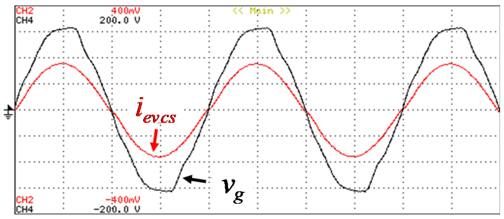
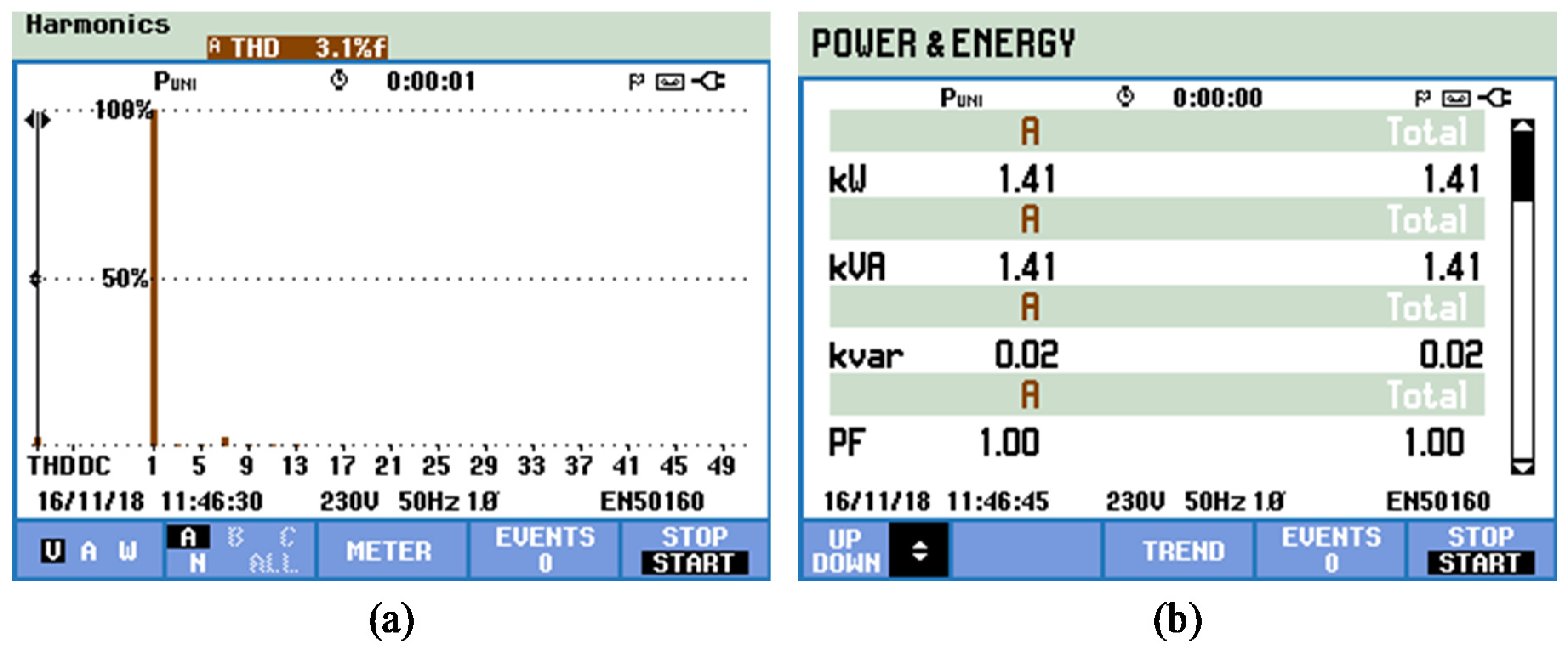
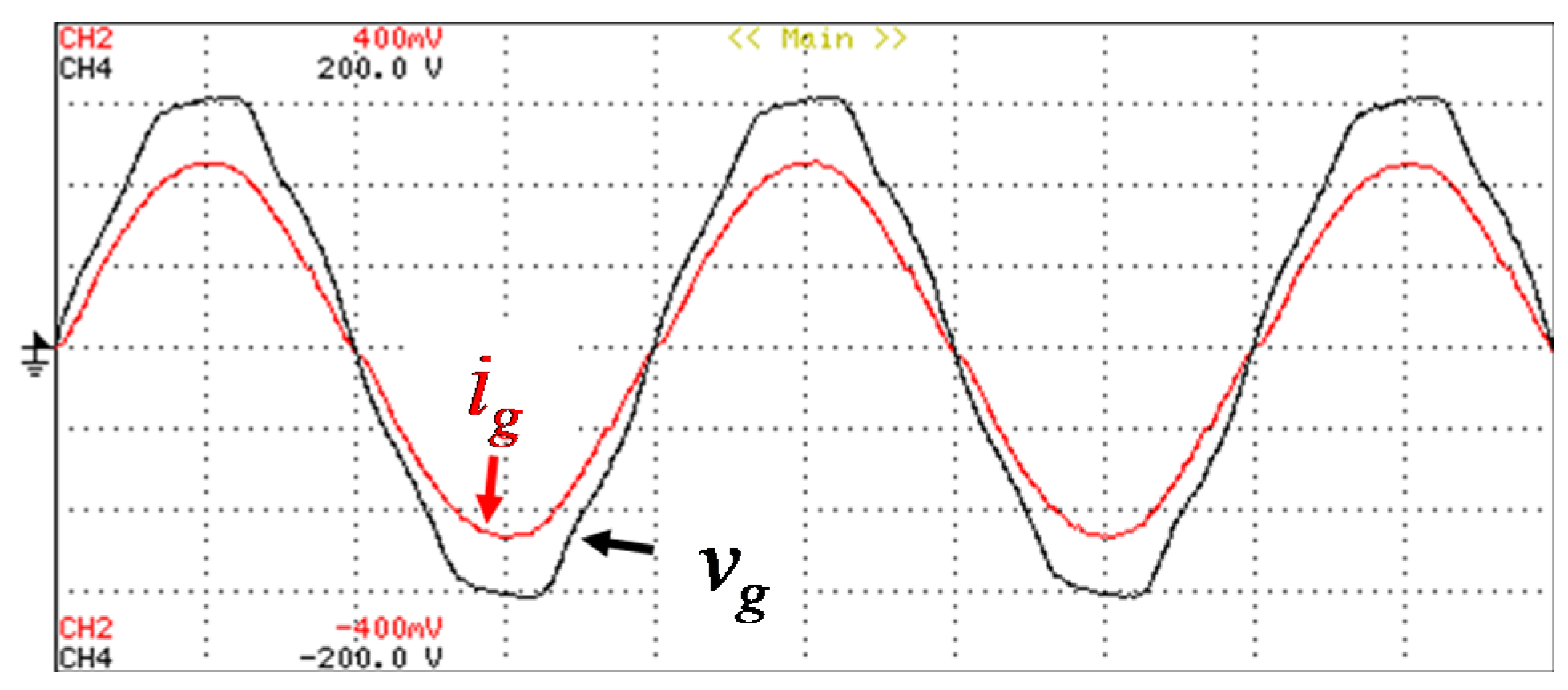
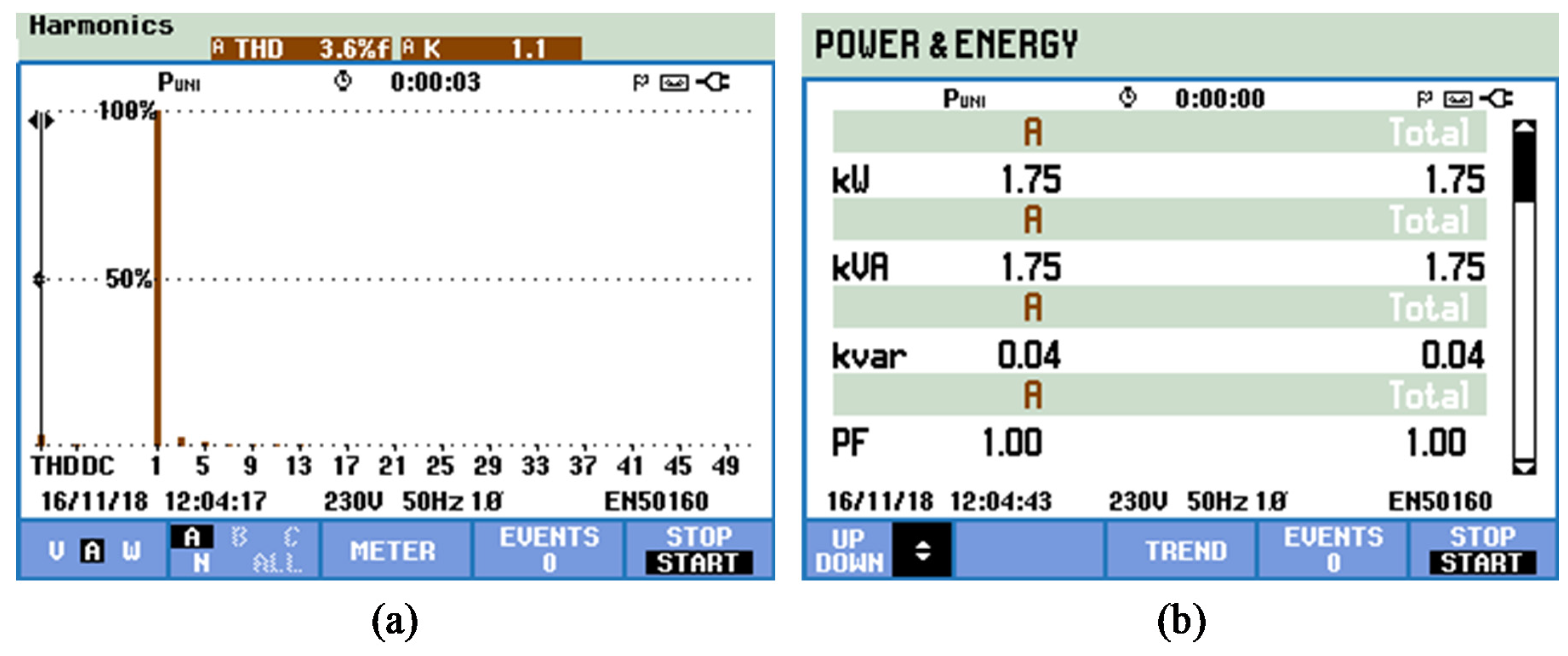
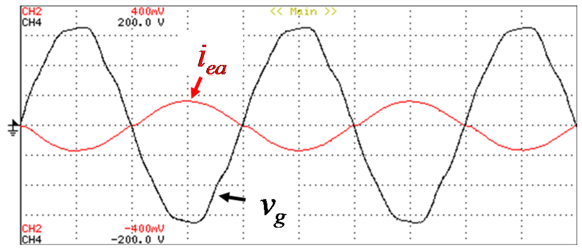
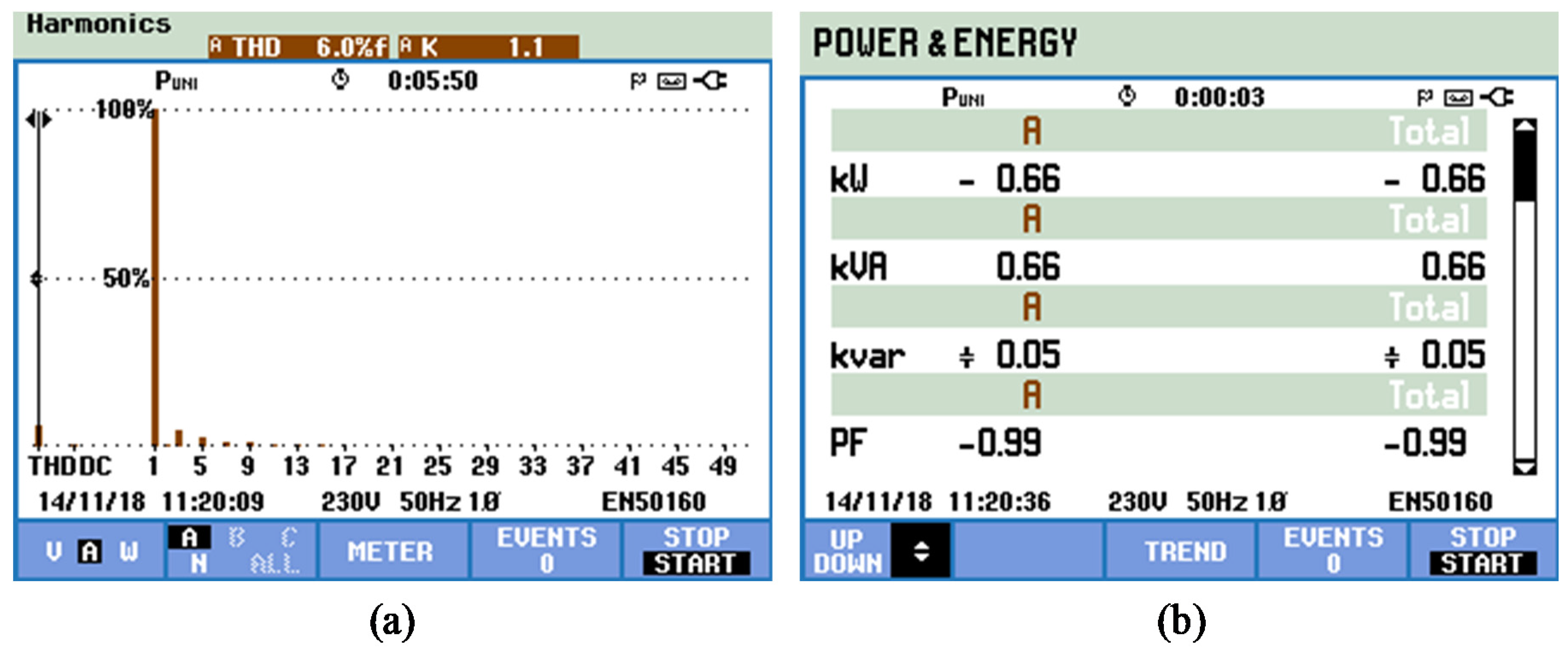
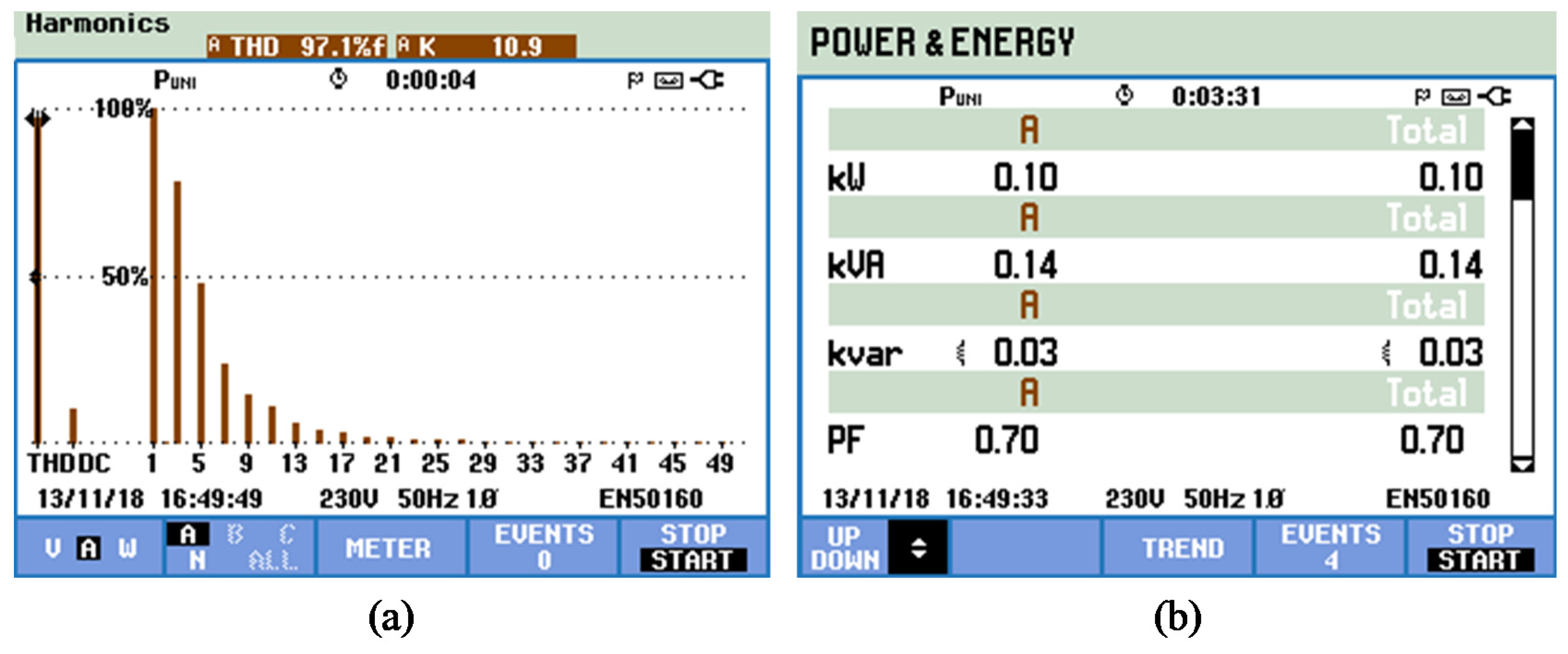
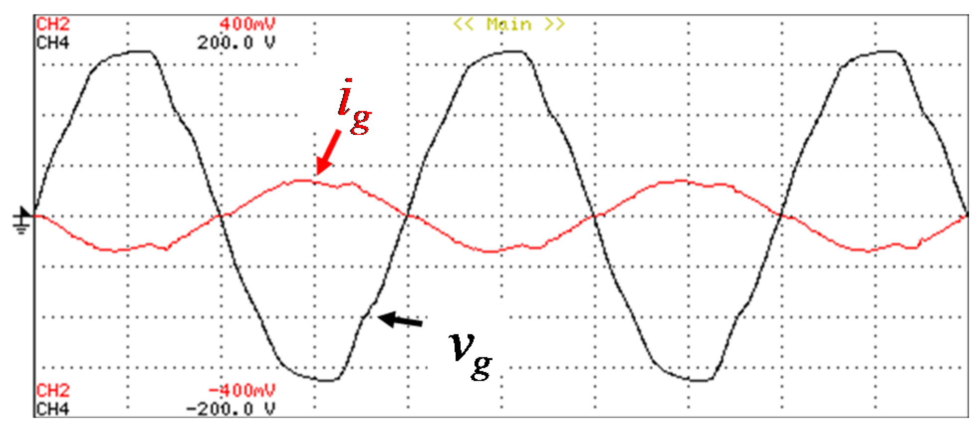
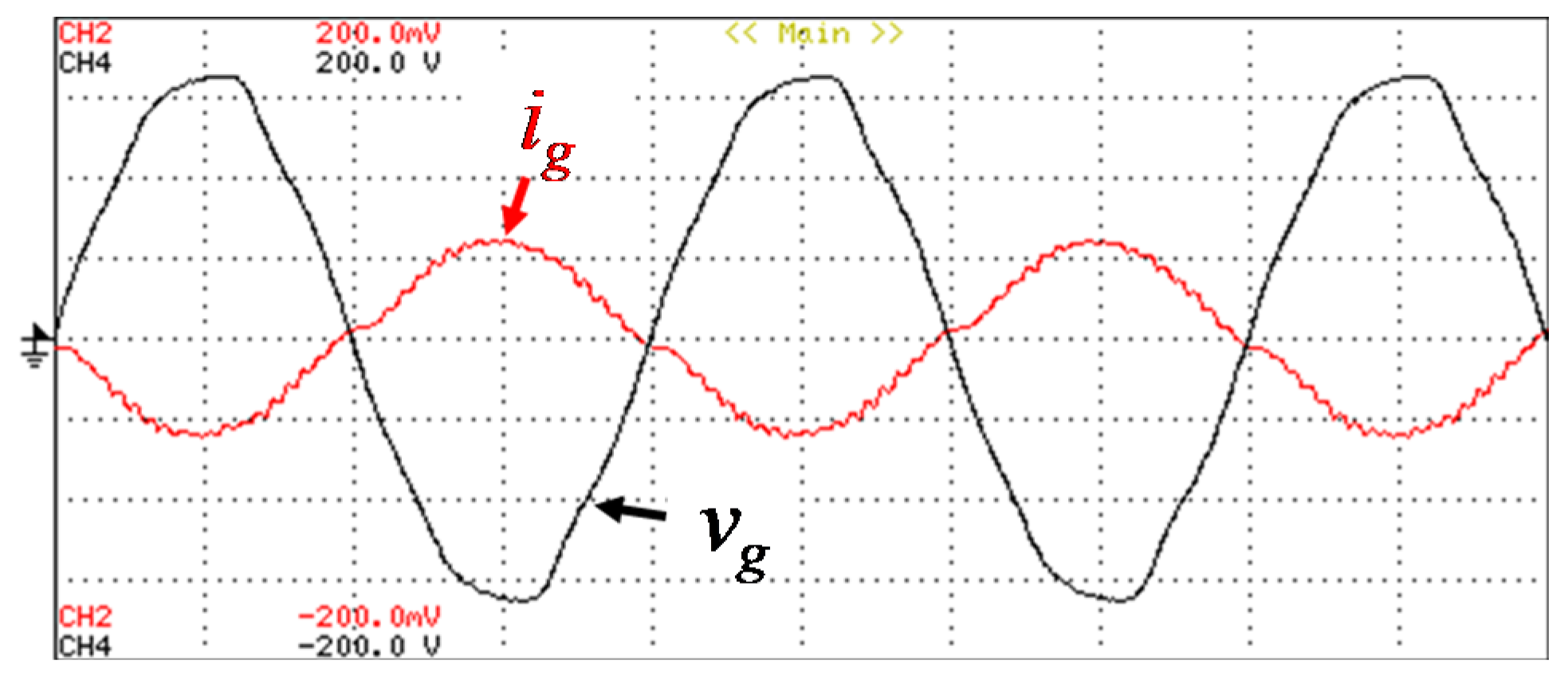
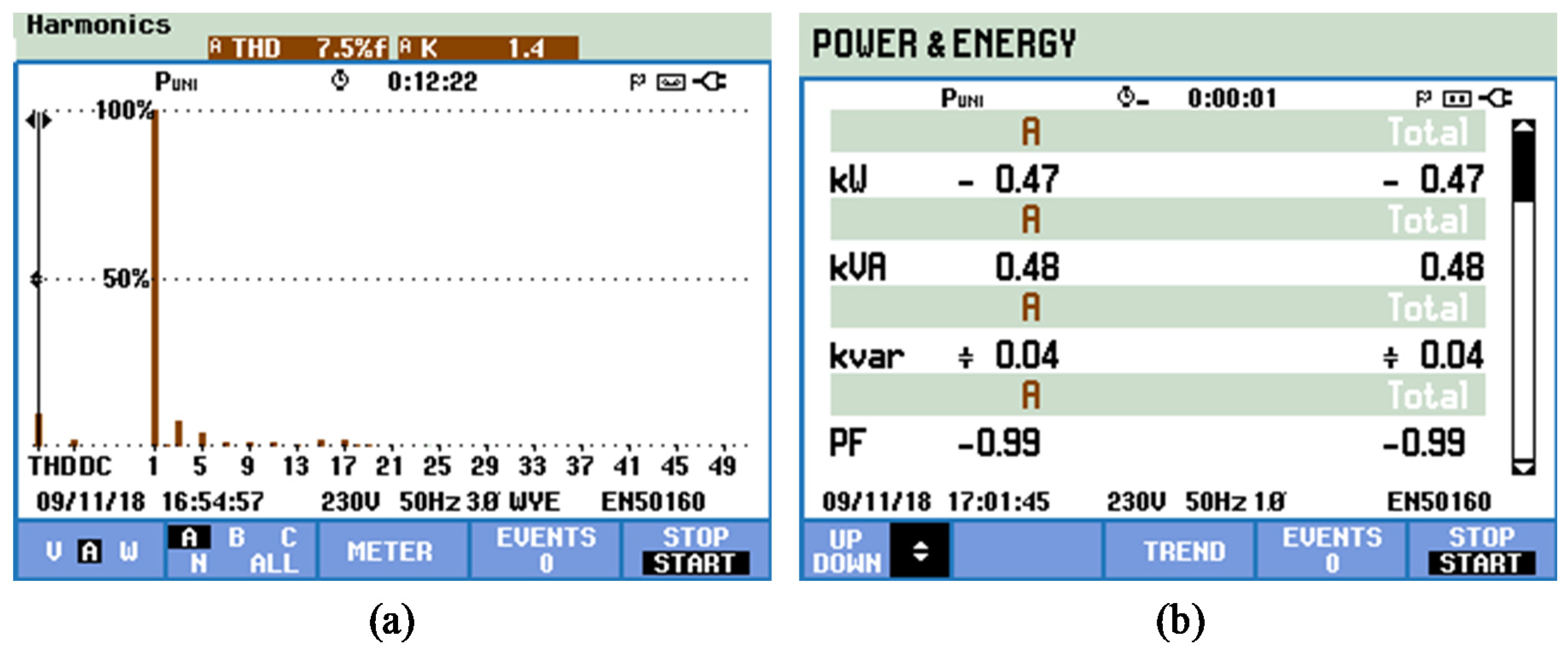
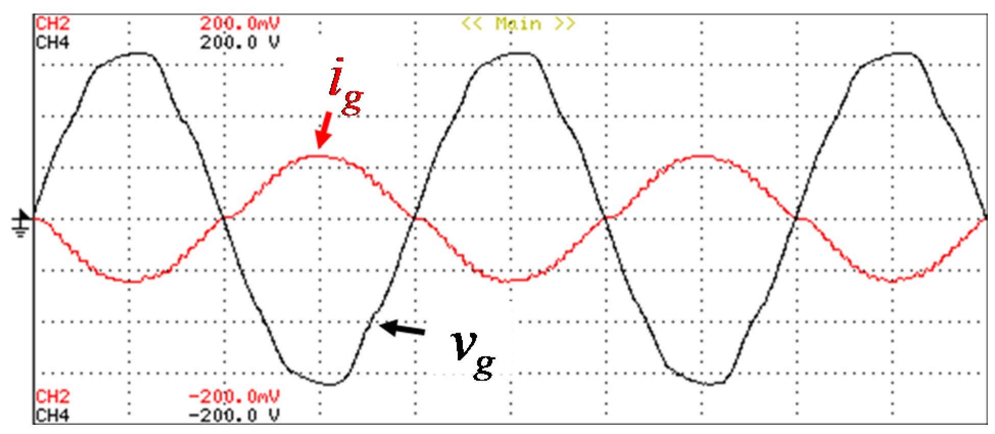
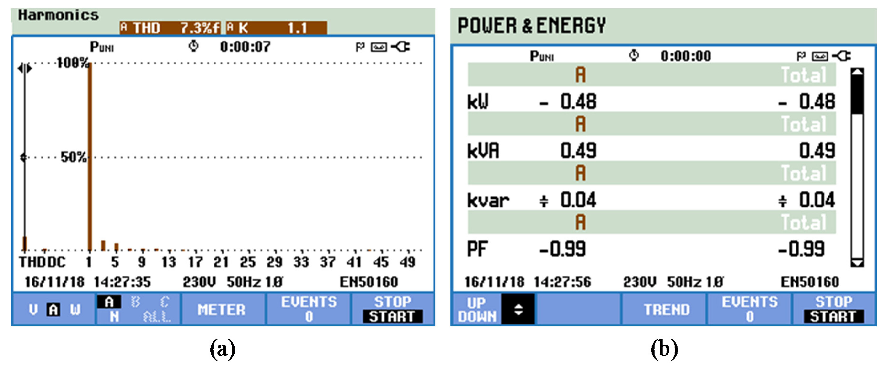
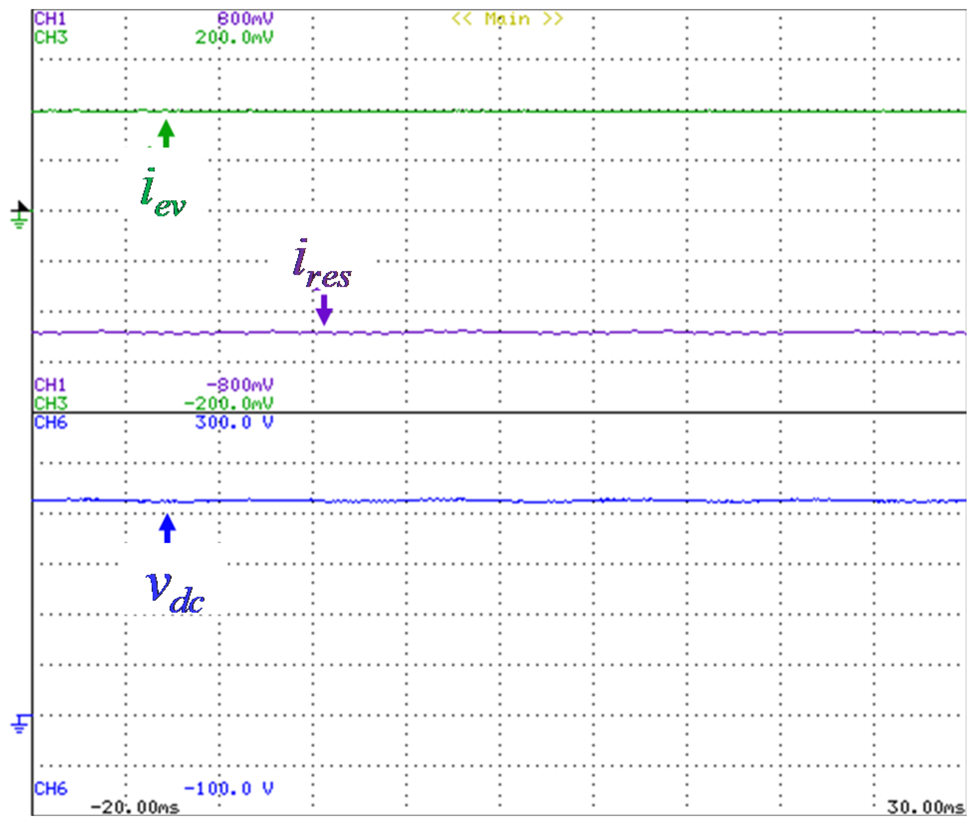
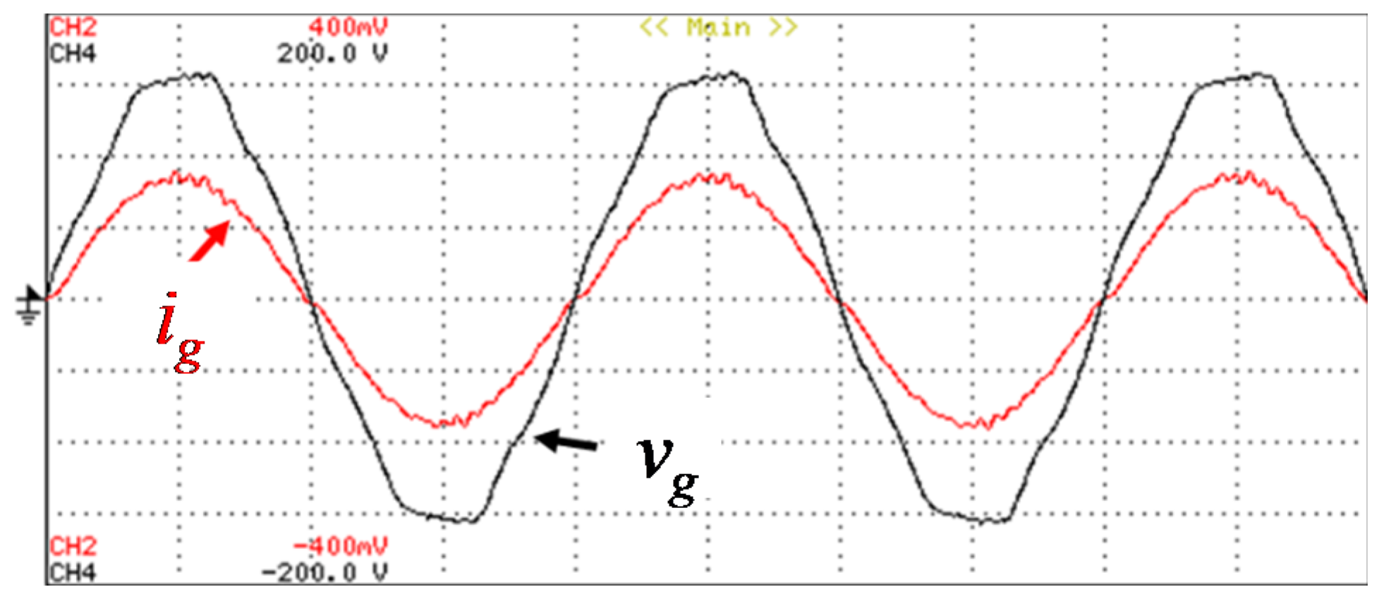
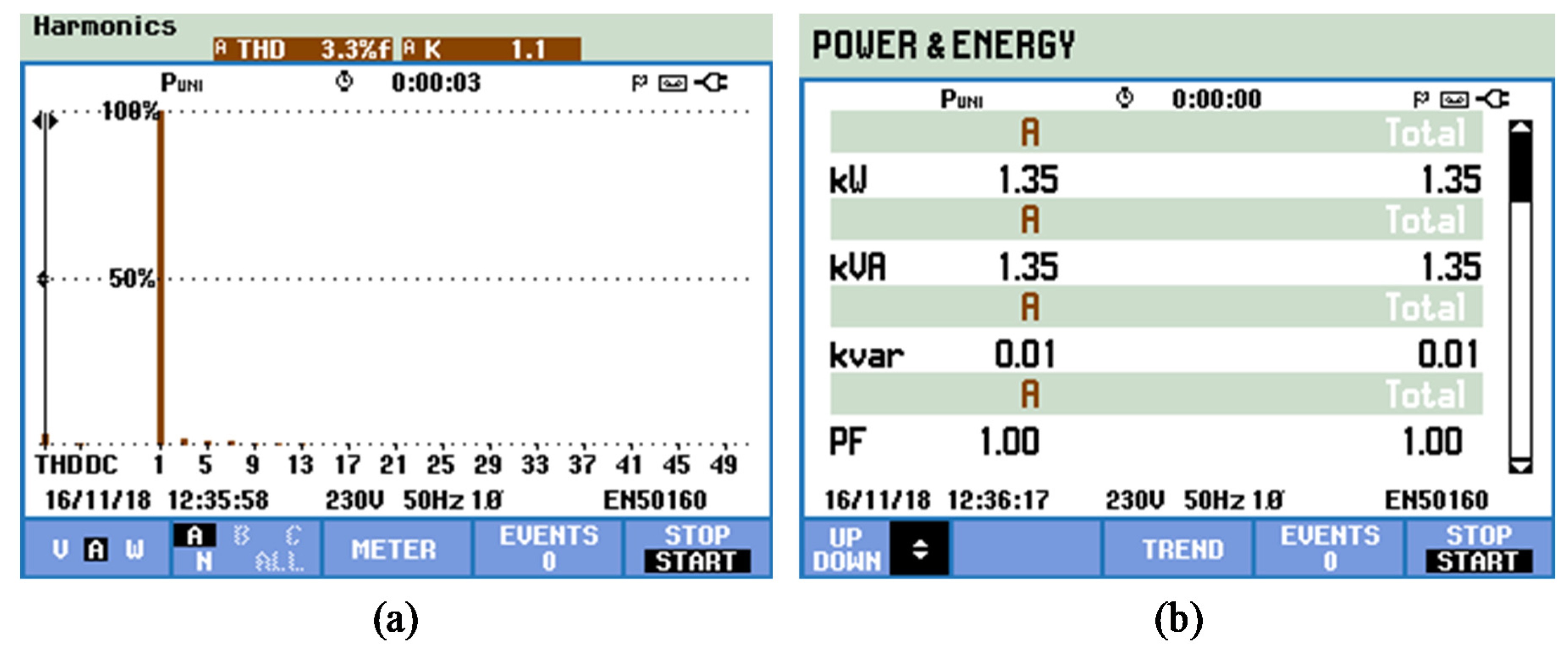
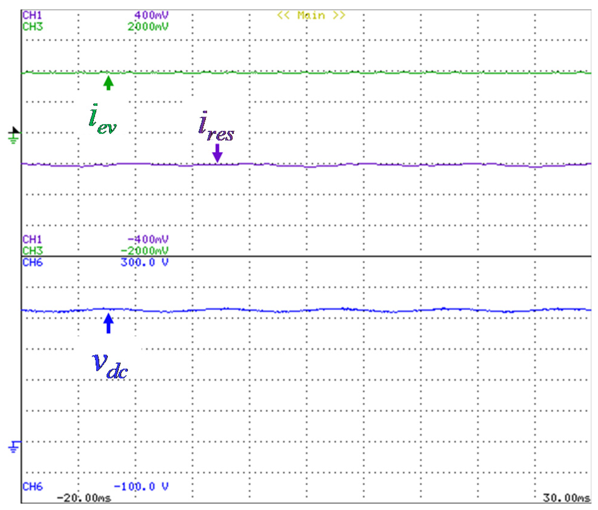
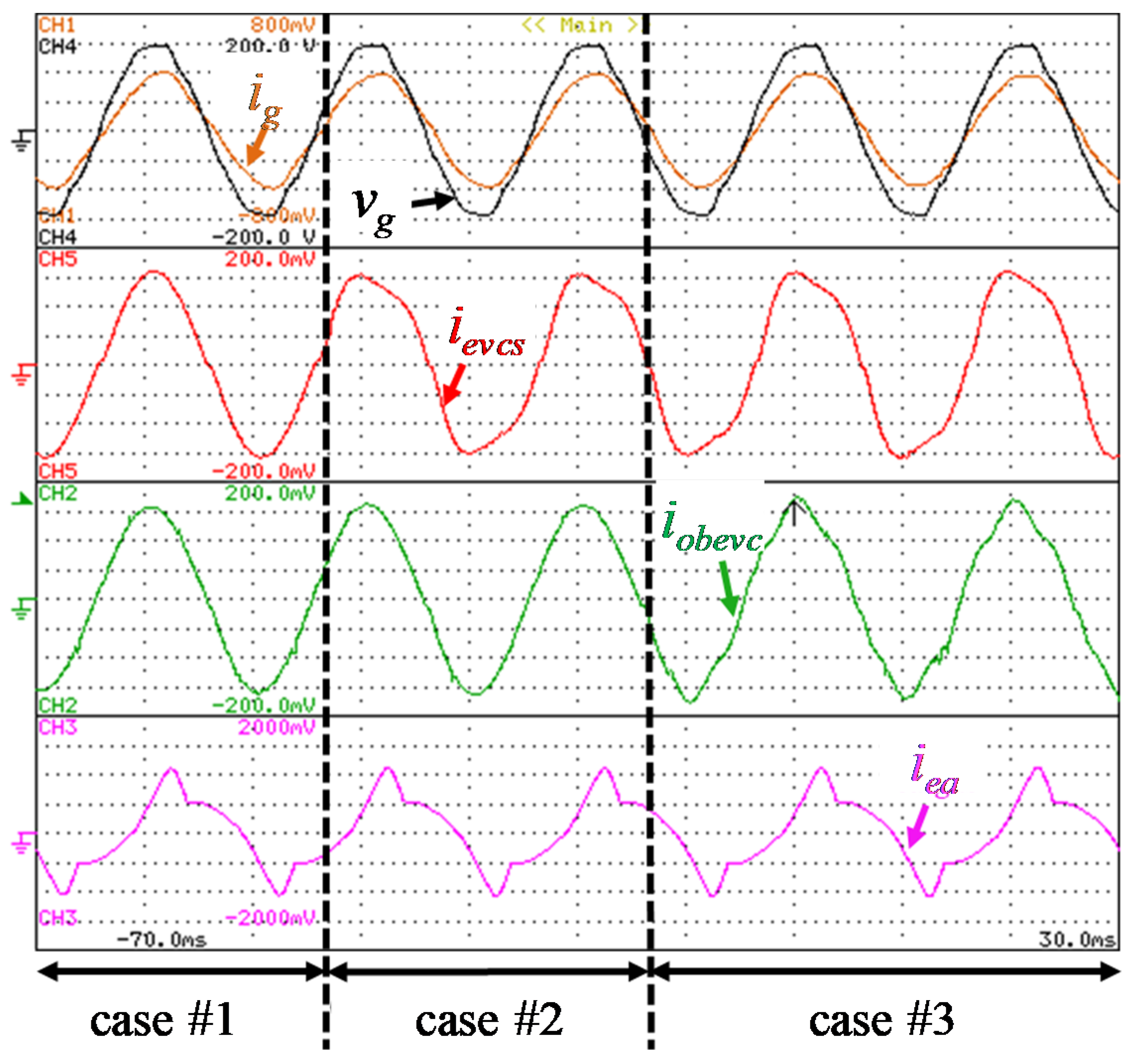
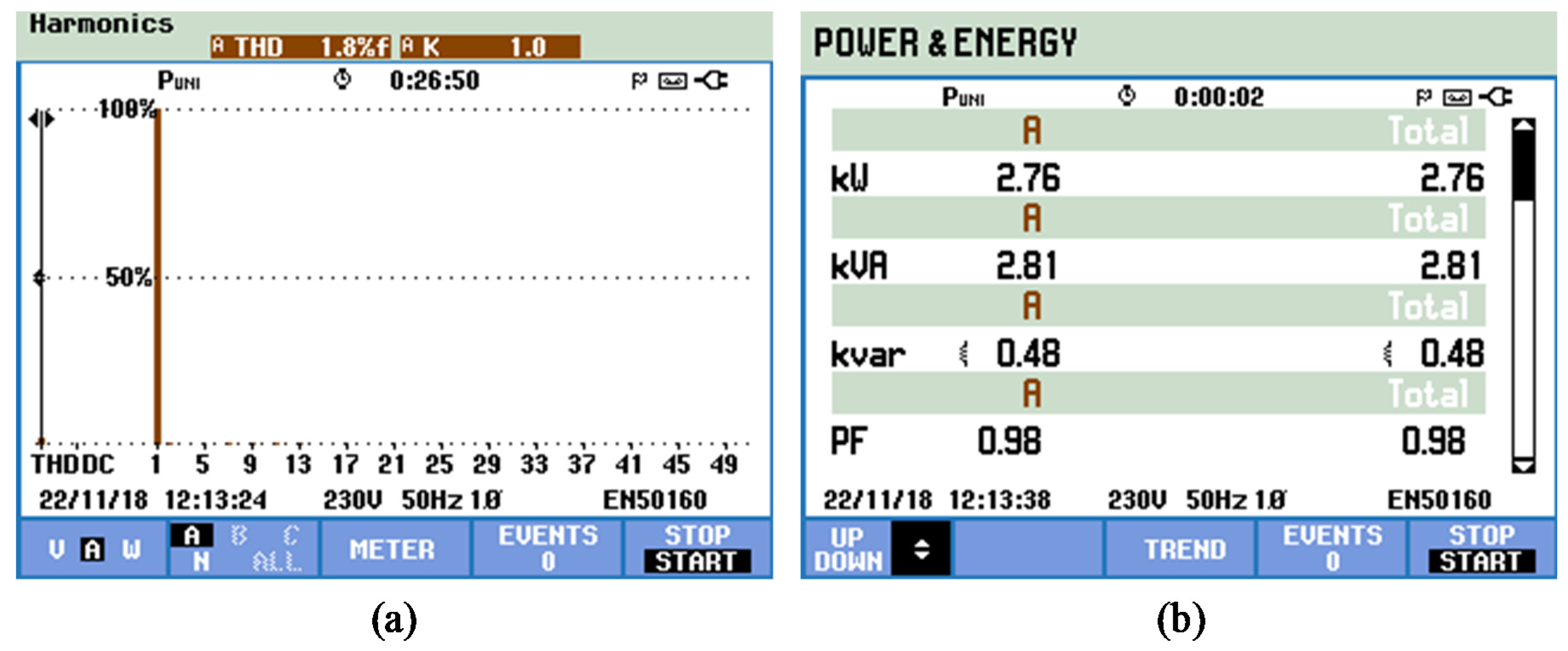
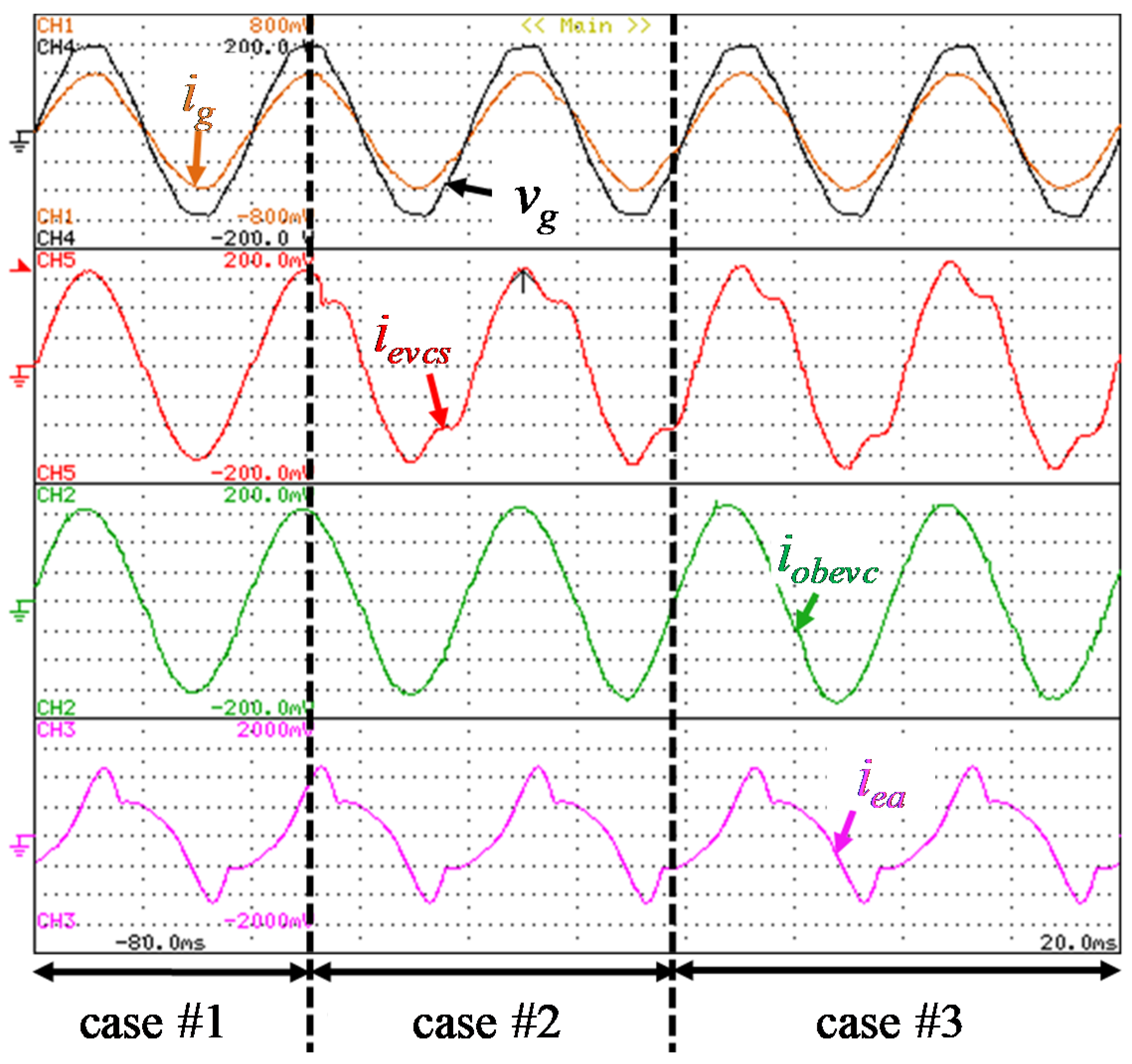
The different operation modes allowed by the proposed MF-EVCS were experimentally validated, and the obtained results are presented in the previous section. During the G2V mode, it is verified the operation with sinusoidal waveform in the ac-side current, presenting a THD of 3.1% and operation with unitary power factor. As demonstrated, the sinusoidal waveform is guaranteed even when the power grid voltage has harmonic distortion, representing an important feature of the proposed MF-EVCS, meaning that it does not contribute to power quality problems in the power grid. This operation mode occurs during the EV battery charging (i.e., when the EV receives energy from the power grid) and the operating power is dependent on the EV requirements. Additionally, this operation mode was also validated considering the MF-EVCS operating as APF, i.e., compensating power quality issues of the smart home where it is installed (i.e., current harmonics and low power factor). The V2G mode is similar in terms of the current waveform in the ac-side, but it is in phase opposition with the voltage, meaning that the MF-EVCS is operating to inject energy into the power grid. In this operation mode, energy from the EV (i.e., a portion of the energy stored in the battery) is used in order to support the smart grid or smart home operation during short periods of time. Similarly to the previous case, this operation mode was also validated considering the MF-EVCS operating as APF, i.e., compensating power quality issues of the smart home where it is installed. Besides the individual G2V and V2G modes, the MF-EVCS was also validated with combined operation modes. During the combined operation of R2G with V2G it was possible to verify that the MF-EVCS can inject energy into the power grid. However, in this case, the injected energy is provided, simultaneously, from both the EV and the RES. This operation mode can be useful to support the smart grid or smart home during short critical periods of time, e.g., when the energy injected from RES is not enough, the EV can contribute with a small amount of energy. Also in this operation mode, it was possible to verify an ac-side current with sinusoidal waveform and in phase opposition with the ac-side voltage. On the other hand, it was also possible to validate the combined operation of R2G with R2V. In this case, it was considered that the energy from RES is used to charge the EV, and the remaining energy is injected into the power grid. This is a relevant operation mode, and occurs when the energy provided by RES is higher than the EV requirements, meaning that the surplus must be injected into the power grid. Therefore, independently of the operating power, in this case, the MF-EVCS operates with sinusoidal ac-side current and in phase opposition with the ac-side voltage. Finally, the combined operation of R2V and G2V was also validated, where the EV is charged with energy from the RES and from the power grid. This operation mode is similar to the previous one (R2G with R2V), but in this case, the EV requires more energy than that produced by the RES, meaning that the power grid must provide the remaining amount of energy. The contribution of the power grid is a function of the energy produced by the RES, i.e., if the EV requirements are constant, the fluctuations of the RES production must be compensated by the power grid. Independently of the operating power, the MF-EVCS operates with a sinusoidal ac-side current and in phase with the ac-side voltage. Additionally, the MF-EVCS was also validated in the context of smart grids, considering that it can be controlled for producing selected current harmonics to the power grid. This validation was carried out with the collaboration of an on-board EV charger. The validation was considered in transient-state, showing that the proposed MF-EVCS can dynamically produce selected current harmonics. Taking into account that the MF-EVCS is controlled for producing selected current harmonics, the ac-side current is not sinusoidal. In counterpart, it contributes to compensate the current harmonic distortion of the electrical installation. Moreover, it is important to note that this possibility of producing selected current harmonics can be combined with the above-mentioned operation modes (e.g., during the G2V mode), representing an attractive operation in the context of smart grids. In fact, this possibility was experimentally validated, as shown in this paper.

6. Conclusions

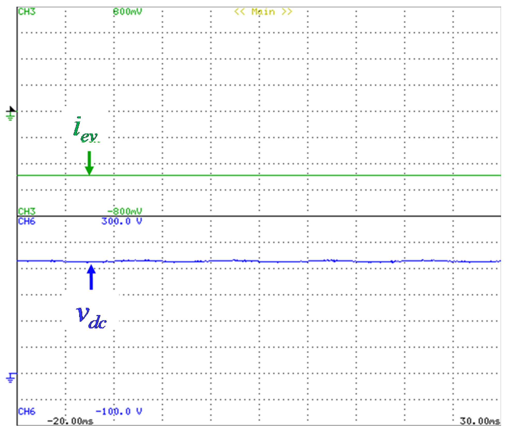
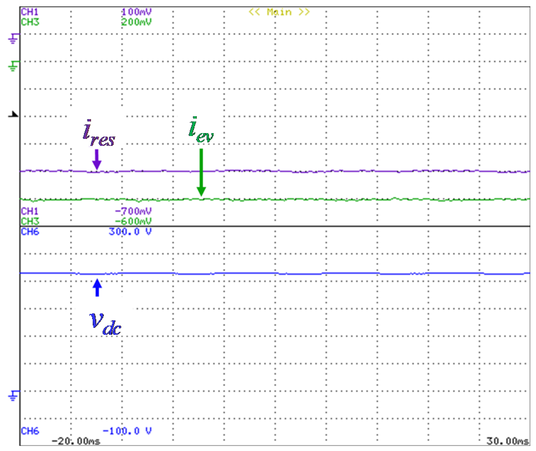
In the context of smart homes and smart grids this paper proposes a single-phase off-board multi-functional electric vehicle (EV) charging station (MF-EVCS) with innovative operation modes. The power electronics topology has a single ac-side interface and two dc-side interfaces, which are capable of interfacing: (a) a renewable energy source (RES); (b) an EV, for performing dc charging or discharging (off-board grid-to-vehicle (G2V) or vehicle-to-grid (V2G) modes). As advantageous features, the proposed MF-EVCS can handle individual operation modes (such as G2V, V2G, RES-to-grid, RES-to-vehicle) or a combination of these modes. Moreover, as an additional innovative contribution, the proposed MF-EVCS can operate, associated with any of the previously mentioned modes, as an APF to support the operation of the power grid with reactive power or/and selected current harmonics. A developed laboratory prototype was presented, as well as a set of relevant experimental results. The results were obtained for several possible cases of operation, showing its suitability for different scenarios. On the ac-side, it was possible to verify the proper operation for the smart home interface, as well as the operation as active power filter (APF) to help to compensate power quality for the smart grid. On the other hand, on the dc-side, it was possible to verify a controlled dc-link voltage, as well as a controlled dc current both in the RES interface and in the EV.
As future perspectives, the possibility of adding more operation modes to the proposed MF-EVCS will be explored. Taking into account that the EV and the RES are connected on the dc-side (i.e. the EV can be seen as an energy storage system), a new operation mode that can be added which is the possibility of the proposed MF-EVCS operating as an off-line uninterruptible power supply. In this sense, it will be necessary a new control layer to detect power outages, to modify the operation of the MF-EVCS during the outage (i.e., operation as a voltage source with voltage control feedback) and to detect the voltage restoration (changing again the MF-EVCS operation). Besides, taking into account that the proposed MF-EVCS was validated in laboratory, as a future task, we expect to evaluate the MF-EVCS in terms of robustness, fault-tolerance and control stability in order to prepare it for real operation scenarios. Moreover, the proposed MF-EVCS will be evaluated under the presented operation modes, but also considering the turn-on and turn-off of more electrical appliances. It is important to note that the MF-EVCS was validated coupled to the power grid, subjected to the typical power quality problems of the power grid. However, as a future objective, the proposed MF-EVCS will be validated under more intensive experimental conditions, aiming to corroborate the advantages of the proposed operation modes, even under critical events related to the operation of the power grid (e.g., voltage sags or short-circuit conditions).

Author Contributions

V.M. performed writing—original draft preparation. V.M. and P.L. performed the literature review, the analysis and the evaluation. All the authors participated in the conceptualization, methodology, and writing—review and editing. All authors have read and agreed to the published version of the manuscript.

Funding

This work has been supported by FCT – Fundação para a Ciência e Tecnologia with-in the Project Scope: UIDB/00319/2020. This work has been supported by the FCT Project newERA4GRIDs PTDC/EEI-EEE/30283/2017, and by the FCT Project DAIPESEV PTDC/EEI-EEE/30382/2017. Tiago Sousa is supported by the doctoral scholarship SFRH/BD/134353/2017 granted by FCT.

Conflicts of Interest

The authors declare no conflict of interest.

References

  1. Lopes, J.P.; Madureira, A.G.; Matos, M.; Bessa, R.J.; Monteiro, V.; Afonso, J.L.; Santos, S.F.; Catalão, J.P.S.; Antunes, C.H.; Magalhães, P. The future of power systems: Challenges, trends, and upcoming paradigms. Wiley Interdiscip. Rev. Energy Environ. 2019. [Google Scholar] [CrossRef]
  2. Leite, R.S.; Afonso, J.L.; Monteiro, V. A Novel Multilevel Bidirectional Topology for On-Board EV Battery Chargers in Smart Grids. Energies 2018, 11, 3453. [Google Scholar] [CrossRef] [Green Version]
  3. Lopez, V.M.; Azcondo, F.; Pigazo, A. Power Quality Enhancement in Residential Smart Grids Through Power Factor Correction Stages. IEEE Trans. Ind. Electron. 2018, 65, 8553–8564. [Google Scholar] [CrossRef] [Green Version]
  4. Islam, S.M.R.; Maxwell, S.; Hossain, K.; Park, S.-Y.; Park, S. Reactive power distribution strategy using power factor correction converters for smart home application. In Proceedings of the IEEE Energy Conversion Congress and Exposition (ECCE), Milwaukee, IL, USA, 18–22 September 2016; pp. 1–6. [Google Scholar]
  5. Javadi, A.; Hamadi, A.; Woodward, L.; Al-Haddad, K. Experimental Investigation on a Hybrid Series Active Power Compensator to Improve Power Quality of Typical Households. IEEE Trans. Ind. Electron. 2016, 63, 4849–4859. [Google Scholar] [CrossRef]
  6. Su, W.; Eichi, H.; Zeng, W.; Chow, M.-Y. A Survey on the Electrification of Transportation in a Smart Grid Environment. IEEE Trans. Ind. Informatics 2011, 8, 1–10. [Google Scholar] [CrossRef]
  7. Skouras, T.A.; Gkonis, P.K.; Ilias, C.N.; Trakadas, P.T.; Tsampasis, E.G.; Zahariadis, T.; Ninikas, K.; Hytiris, N.; Emmanuel, R.; Aaen, B. Electrical Vehicles: Current State of the Art, Future Challenges, and Perspectives. Clean Technol. 2020, 2, 1–16. [Google Scholar] [CrossRef] [Green Version]
  8. Monteiro, V.; Afonso, J.; Ferreira, J.C.; Afonso, J.L. Vehicle Electrification: New Challenges and Opportunities for Smart Grids. Energies 2018, 12, 118. [Google Scholar] [CrossRef] [Green Version]
  9. Yilmaz, M.; Krein, P.T. Review of the Impact of Vehicle-to-Grid Technologies on Distribution Systems and Utility Interfaces. IEEE Trans. Power Electron. 2013, 28, 5673–5689. [Google Scholar] [CrossRef]
  10. Rajashekara, K. Present Status and Future Trends in Electric Vehicle Propulsion Technologies. IEEE J. Emerg. Sel. Top. Power Electron. 2013, 1, 3–10. [Google Scholar] [CrossRef]
  11. Milberg, J.; Schlenker, A. Plug into the Future. IEEE Power Energy Mag. 2010, 9, 56–65. [Google Scholar] [CrossRef]
  12. Liu, C.; Chau, K.T.; Wu, D.; Gao, S. Opportunities and Challenges of Vehicle-to-Home, Vehicle-to-Vehicle, and Vehicle-to-Grid Technologies. Proc. IEEE 2013, 101, 2409–2427. [Google Scholar] [CrossRef] [Green Version]
  13. Monteiro, V.; Pinto, J.G.; Afonso, J.L. Operation Modes for the Electric Vehicle in Smart Grids and Smart Homes: Present and Proposed Modes. IEEE Trans. Veh. Technol. 2015, 65, 1007–1020. [Google Scholar] [CrossRef] [Green Version]
  14. Boulanger, A.; Chu, A.C.; Maxx, S.; Waltz, D.L. Vehicle Electrification: Status and Issues. Proc. IEEE 2011, 99, 1116–1138. [Google Scholar] [CrossRef] [Green Version]
  15. Monteiro, V.; Ferreira, J.C.; Couto, C.; Afonso, J.L.; Melendez, A.A.N. Experimental Validation of a Novel Architecture Based on a Dual-Stage Converter for Off-Board Fast Battery Chargers of Electric Vehicles. IEEE Trans. Veh. Technol. 2017, 67, 1000–1011. [Google Scholar] [CrossRef] [Green Version]
  16. Moses, P.S.; Deilami, S.; Masoum, A.S.; Masoum, M.A.S. Power quality of smart grids with Plug-in Electric Vehicles considering battery charging profile. In Proceedings of the 2010 IEEE PES Innovative Smart Grid Technologies Conference Europe (ISGT Europe), Gothenburg, Sweden, 11–13 October 2010; pp. 1–7. [Google Scholar]
  17. Clement-Nyns, K.; Haesen, E.; Driesen, J. The Impact of Charging Plug-In Hybrid Electric Vehicles on a Residential Distribution Grid. IEEE Trans. Power Syst. 2009, 25, 371–380. [Google Scholar] [CrossRef] [Green Version]
  18. Zhang, T.; Chen, W.; Han, Z.; Cao, Z. Charging Scheduling of Electric Vehicles with Local Renewable Energy Under Uncertain Electric Vehicle Arrival and Grid Power Price. IEEE Trans. Veh. Technol. 2013, 63, 2600–2612. [Google Scholar] [CrossRef] [Green Version]
  19. Lu, X.; Liu, N.; Chen, Q.; Zhang, J. Multi-objective optimal scheduling of a DC micro-grid consisted of PV system and EV charging station. In Proceedings of the IEEE ISGT Innovative Smart Grid Technologies, Washington, DC, USA, 19–22 February 2014; pp. 487–491. [Google Scholar]
  20. Gungor, V.; Sahin, D.; Kocak, T.; Ergut, S.; Buccella, C.; Cecati, C.; Hancke, G.P. Smart Grid and Smart Homes: Key Players and Pilot Projects. IEEE Ind. Electron. Mag. 2012, 6, 18–34. [Google Scholar] [CrossRef]
  21. Mozos, A.B.D.L.; Mouli, G.R.C.; Bauer, P. Evaluation of topologies for a solar powered bidirectional electric vehicle charger. IET Power Electron. 2019, 12, 3675–3687. [Google Scholar] [CrossRef]
  22. Saber, A.Y.; Venayagamoorthy, G.K. Plug-in Vehicles and Renewable Energy Sources for Cost and Emission Reductions. IEEE Trans. Ind. Electron. 2010, 58, 1229–1238. [Google Scholar] [CrossRef]
  23. Moslehi, K.; Kumar, R. A Reliability Perspective of the Smart Grid. IEEE Trans. Smart Grid 2010, 1, 57–64. [Google Scholar] [CrossRef]
  24. Chen, C.; Duan, S. Optimal Integration of Plug-In Hybrid Electric Vehicles in Microgrids. IEEE Trans. Ind. Informatics 2014, 10, 1917–1926. [Google Scholar] [CrossRef]
  25. Lopes, J.A.P.; Soares, F.J.; Almeida, P.M.; Da Silva, M.M. Smart Charging Strategies for Electric Vehicles: Enhancing Grid Performance and Maximizing the Use of Variable Renewable Energy Resources. In Proceedings of the EVS24 International Battery, Hybrid and Fuel Cell Electric Vehicle Symposium, Stavanger, Norway, 13–16 May 2009; pp. 1–11. [Google Scholar]
  26. Sortomme, E.; Hindi, M.M.; MacPherson, S.D.J.; Venkata, S.S. Coordinated Charging of Plug-In Hybrid Electric Vehicles to Minimize Distribution System Losses. IEEE Trans. Smart Grid 2010, 2, 198–205. [Google Scholar] [CrossRef]
  27. Gao, S.; Chau, K.T.; Liu, C.; Wu, D.; Chan, C.C. Integrated Energy Management of Plug-in Electric Vehicles in Power Grid with Renewables. IEEE Trans. Veh. Technol. 2014, 63, 3019–3027. [Google Scholar] [CrossRef]
  28. Traube, J.; Lu, F.; Maksimović, D. Electric vehicle DC charger integrated within a photovoltaic power system. In Proceedings of the IEEE APEC Applied Power Electronics Conference and Exposition, Orlando, FL, USA, 5–9 February 2012; pp. 352–358. [Google Scholar]
  29. Traube, J.; Lu, F.; Mossoba, J.; Kromer, M.; Faill, P.; Katz, S.; Borowy, B.; Nichols, S.; Casey, L.; Maksimovic, D. Mitigation of Solar Irradiance Intermittency in Photovoltaic Power Systems with Integrated Electric-Vehicle Charging Functionality. IEEE Trans. Power Electron. 2012, 28, 3058–3067. [Google Scholar] [CrossRef]
  30. Jalakas, T.; Roasto, I.; Gallardo-Lozano, J.; Romero-Cadaval, E. Electric vehicle multiport fast charger based on the concept of active power electronic transformer. In Proceedings of the EPE European Conference on Power Electronics and Applications, Lappeenranta, Finland, 26–28 August 2014; pp. 1–9. [Google Scholar]
  31. Monteiro, V.; Sousa, T.; Couto, C.; Martins, J.; Melendez, A.A.N.; Afonso, J.L. A Novel Multi-Objective Off-Board EV Charging Station for Smart Homes. In Proceedings of the IEEE IECON Industrial Electronics Conference, Washington, DC, USA, 21–23 October 2018; pp. 1983–1988. [Google Scholar]
  32. Monteiro, V.; Sousa, T.; Afonso, J.A.; Afonso, J.L. Innovative Off-Board EV Home Charging Station as a Smart Home Enabler: Present and Proposed Perspectives. In Proceedings of the IEEE INDIN International Conference on Industrial Informatics, Porto, Portugal, 18–20 July 2018; pp. 966–971. [Google Scholar]
Figure 1. Multi-functional EV charging station (MF-EVCS): (a) General overview in the context of a smart home; (b) Internal constitution regarding the structures of the converters.
Energies 13 01864 g001
Figure 2. Experimental setup with the developed MF-EVCS prototype.
Energies 13 01864 g002
Figure 3. Experimental results during the MF-EVCS operation in G2V mode: Ac-side voltage(vg: 50 V/div) and ac-side current (ievcs: 10 A/div).
Energies 13 01864 g003
Figure 4. Experimental results during the MF-EVCS operation in G2V mode: (a) Harmonic spectrum of the ac-side current (ievcs); (b) Operating powers and total power factor.
Energies 13 01864 g004
Figure 5. Experimental results during the MF-EVCS operation in G2V mode: Current in the EV battery (iev: 2 A/div) and dc-link voltage (vdc: 50 V/div).
Energies 13 01864 g005
Figure 6. Experimental results without the operation of the MF-EVCS (in G2V mode): Ac-side voltage (vg: 50 V/div); Electrical appliances current (iea: 10 A/div).
Energies 13 01864 g006
Figure 7. Experimental results without the operation of the MF-EVCS (in G2V mode): (a) Harmonic spectrum of the electrical appliances current (iea); (b) Operating powers and total power factor.
Energies 13 01864 g007
Figure 8. Experimental results during the MF-EVCS operation in G2V mode combined with the operation as APF: Ac-side voltage (vg: 50 V/div); Total home current (ig: 10 A/div).
Energies 13 01864 g008
Figure 9. Experimental results during the MF-EVCS operation in G2V mode combined with the operation as APF: (a) Harmonic spectrum of the total home current (ig); (b) Operating powers and total power factor.
Energies 13 01864 g009
Figure 10. Experimental results during the MF-EVCS operation in V2G mode: Ac-side voltage (vg: 50 V/div) and ac-side current (ievcs: 10 A/div).
Energies 13 01864 g010
Figure 11. Experimental results during the MF-EVCS operation in V2G mode: (a) Harmonic spectrum of the ac-side current (ievcs); (b) Operating powers and total power factor.
Energies 13 01864 g011
Figure 12. Experimental results during the MF-EVCS operation in V2G mode: Current in the EV battery (iev: 2 A/div) and dc-link voltage (vdc: 50 V/div).
Energies 13 01864 g012
Figure 13. Experimental results without the operation of the MF-EVCS (in V2G mode): Ac-side voltage (vg: 50 V/div); Electrical appliances current (iea: 10 A/div).
Energies 13 01864 g013
Figure 14. Experimental results without the operation of the MF-EVCS (in V2G mode): (a) Harmonic spectrum of the electrical appliances current (iea); (b) Operating powers and total power factor.
Energies 13 01864 g014
Figure 15. Experimental results during the MF-EVCS operation in V2G mode combined with the operation as APF: Ac-side voltage (vg: 50 V/div); Total home current (ig: 10 A/div).
Energies 13 01864 g015
Figure 16. Experimental results during the MF-EVCS operation in V2G mode combined with the operation as APF: (a) Harmonic spectrum of the total home current (ig); (b) Operating powers and total power factor.
Energies 13 01864 g016
Figure 17. Experimental results during the MF-EVCS operation in R2G mode combined with V2G mode: Ac-side voltage (vg: 50 V/div); Total home current (ig: 5 A/div).
Energies 13 01864 g017
Figure 18. Experimental results during the MF-EVCS operation in R2G mode combined with V2G mode: (a) Harmonic spectrum of the total home current (ig); (b) Operating powers and total power factor.
Energies 13 01864 g018
Figure 19. Experimental results during the MF-EVCS operation in R2G mode combined with V2G mode: Current in the EV battery (iev: 0.5 A/div); Current in the RES interface (ires: 2 A/div); Dc-link voltage (vdc: 50 V/div).
Energies 13 01864 g019
Figure 20. Experimental results during the MF-EVCS operation in R2G mode combined with R2V mode: ac-side voltage (vg: 50 V/div); Total home current (ig: 5 A/div).
Energies 13 01864 g020
Figure 21. Experimental results during the MF-EVCS operation in R2G mode combined with R2V mode: (a) Harmonic spectrum of the total home current (ig); (b) Operating powers and total power factor.
Energies 13 01864 g021
Figure 22. Experimental results during the MF-EVCS operation in R2G mode combined with R2V mode: Current in the EV battery (iev: 0.5 A/div); Current in the RES interface (ires: 2 A/div); Dc-link voltage (vdc: 50 V/div).
Energies 13 01864 g022
Figure 23. Experimental results during the MF-EVCS operation in R2G mode combined with G2V mode: Ac-side voltage (vg: 50 V/div); Total home current (ig: 10 A/div).
Energies 13 01864 g023
Figure 24. Experimental results during the MF-EVCS operation in R2G mode combined with G2V mode: (a) Harmonic spectrum of the total home current (ig); (b) Operating powers and total power factor.
Energies 13 01864 g024
Figure 25. Experimental results during the MF-EVCS operation in R2G mode combined with G2V mode: Current in the EV battery (iev: 2 A/div); Current in the RES interface (ires: 1 A/div); Dc-link voltage (vdc: 50 V/div).
Energies 13 01864 g025
Figure 26. Experimental results during the MF-EVCS operation combined with the operation of an on-board EV charger (compensating current harmonics): Ac-side voltage (vg: 50 V/div); Total home current (ig: 20 A/div); Ac-side current of the MF-EVCS (ievcs: 5 A/div); Ac-side current of the on-board EV charger (iobevc: 5 A/div); Current consumed by the electrical appliances (iea: 5 A/div).
Energies 13 01864 g026
Figure 27. Experimental results during the MF-EVCS operation combined with the operation of an on-board EV charger (compensating current harmonics): (a) Harmonic spectrum of the total home current (ig); (b) Operating powers and total power factor.
Energies 13 01864 g027
Figure 28. Experimental results during the MF-EVCS operation combined with the operation of an on-board EV charger (compensating current harmonics and power factor): Ac-side voltage (vg: 50 V/div); Total home current (ig: 20 A/div); Ac-side current of the MF-EVCS (ievcs: 5 A/div); Ac-side current of the on-board EV charger (iobevc: 5 A/div); Current consumed by the electrical appliances (iea: 5 A/div).
Energies 13 01864 g028
Figure 29. Experimental results during the MF-EVCS operation combined with the operation of an on-board EV charger (compensating current harmonics and power factor): (a) Harmonic spectrum of the total home current (ig); (b) Operating powers and total power factor.
Energies 13 01864 g029

