Abstract
Induction heating is one of the most effective methods of energy conversion from the electrical to thermal form, used in diverse industrial processes. In this paper the resonance generators for induction heating are considered for which the equivalent load resistance has a strong impact on the ability of the system to use optimally the potentially available power. The equivalent load resistance varies, depending on the type of induction heating system (IHS) and during the heating process itself. This paper presents an induction heat generator in which an L-LC resonance system (called the LLC system) plays an active role in energy matching. The LLC resonance system is analyzed from the point of view of both the functional dependencies describing the influence of frequency on the load resistance transformation, and the impact of the LLC setup on the sensitivity of the generator to changes in the charge resistance caused by heating. The procedure for initial selection of the resonance system parameters is presented. We also consider the possibility of automatic correction by the generator of the LLC system parameters, in order to limit the effect of changes in the IHS parameters on the degree of source–load energy matching. We describe cascade power control algorithms based on the use of Field Programmable Gate Array (FPGA) systems, which enable the optimal control of energy matching. Our study is based on theoretical considerations, numerical simulations, and experimental verification using a 30 kW model.
1. Introduction
Resonant inverters are currently the dominant group of power sources in industrial induction heating technologies. They realize the energy conversion from the electrical to thermal form through high frequency electromagnetic field generation, which penetrates a heated charge. The use of Insulated Gate Bipolar Transistor (IGBT) and Metal-Oxide Semiconductor Field-Effect Transistors (MOSFET) allows the implementation of sources with both high powers exceeding 1 MW and high frequencies over 500 kHz [1,2]. Current or voltage inverters may be used, although the latter are more common in practice, for reasons that are both structural (including easier control) and technological. A typical topology for resonant voltage inverters used in induction heating systems (IHS) is based on a second order LC series resonant system, in which the IHS is an essential part of the inductance and resistance of the resonance circuit. Although they have a number of advantages, resonant sources also cause the changes in the electrical parameters of the IHS (resistance RIHS and inductance LIHS) to affect the operation of the source. As well as changing the frequency, this may also worsen energy matching, reducing optimal usage of the power potentially available from the source. Changing the type of IHS can cause up to several hundred-fold differences in the RIHS resistance or LIHS inductance. However, in industrial practice a given power source is usually loaded with an IHS that has similar electrical parameters, especially the RIHS resistance value, which does not typically differ by more than around tenfold. During the induction heating process itself, several-fold changes in the IHS electrical parameters may also be observed, in comparison to the values for a “cold” charge [3]. In various technical solutions, LC-type oscillation systems can be used for various purposes, as now in triboelectric nanogenerators to boost the performance of transferring energy to a storage unit [4,5]. In induction heating generators matching transformers are now often supported by complex passive systems, which together with IHS create resonance systems mainly of the third [6,7,8,9,10] and fourth [11,12] orders, allowing for an additional effect of impedance transformation. Figure 1 presents three basic solutions for third-order LLC, CLC, and CLL resonance systems found in the literature.
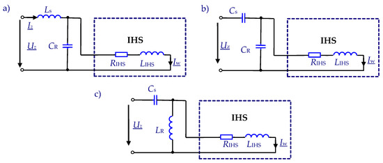
Figure 1.
Third-order resonance systems: (a) LLC, (b) CLC, and (c) CLL.
In addition to serving as resonance and energy matching systems, oscillating systems should also limit the effects of various faults, which may appear, such as load short-circuits or disturbances in the control. For this reason, in practical solutions [13,14,15,16] the LLC topology shown in Figure 1a is preferred, because its additional inductance Ls performs the function of stabilizing changes in the current value of the inverter. This facilitates the operation of diagnostic systems and allows the control system to more effectively eliminate the risk of possible damage to the semiconductors.
The equivalent impedance ZEQ = REQ + jXEQ = Uz/Iz of the LLC system shown in Figure 1a is described by the relationship:
where ω = 2πf is pulsation, f is frequency, CR is resonance capacitor, and RIHS and LIHS is the resistance and inductance of IHS.
In the LLC system, the resonance state can potentially occur at two different values of the resonance frequency fr for which the complex equivalent impedance of the resonance system has only the real part, equal to a certain equivalent resonance resistance REQ. The resonant state is strongly required as it assures the optimal energy conversion. Using Equation (1), Figure 2 shows an example (for two values of series inductance Ls = 3 μH and Ls = 6 μH) of the frequency influence on both the equivalent resistance REQ(f) and the equivalent reactance XEQ(f) = ω LEQ(f) of the LLC system. The values for the other elements of the system are assumed to be CR = 10 μF, RIHS = 55 mΩ, and LIHS = 2 μH. As can be seen in Figure 2, by changing the operating frequency it is possible to change the value of the REQ(f) resistance within a very wide range, for a constant value of RIHS resistance. This can be interpreted as a frequency-dependent resistance transformation ratio (matching ratio) . Resonance systems, especially of a higher order such as LLC, can therefore perform the function of transforming the resistance value, with the transformation coefficient pR(f) being a function of the operating frequency.
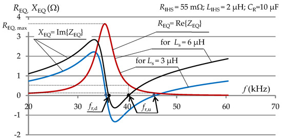
Figure 2.
The waveforms of the equivalent resistance and reactance of the LLC system as a function of frequency.
In this study, we analyze and show how to use the functionality of an LLC induction heating generator in such a way that the power source automatically implements the process of energy matching to load. This applies to both matching a certain set of IHS that differ in their RIHS resistance and LIHS inductance values (static matching for “cold” charges), and matching during the heating process (dynamic matching). The article is organized as follows. In Section 2, the LLC resonance system is analyzed from the point of view of functional relationships describing the influence of frequency on the resistance transformation effect. Taking into account the source–load interaction, exemplary numerical simulations of the charge heating process were performed, showing how changes in the parameters of the heated charge have an impact on the parameters (mainly the equivalent resistance) of the whole source resonance system (i.e., the sensitivity of the resonance system to changes in the input parameters). The sensitivity of the LLC resonance system is then compared with that of series and parallel resonance systems. Section 3 presents a procedure that allows the source to automatically perform static matching to the load. Section 4 presents a practical solution for a resonant source, along with measurement and control systems enabling the implementation of energy self-matching functions. Section 5 is devoted to the issue of cascading power control, which limits the need to use the controlled LLC matching system (except when absolutely necessary), by preferring other methods. Section 6 presents the results of experimental studies, and Section 7 provides a summary of the research.
2. Transformation of Resonance Resistance in an LLC System
As shown in Figure 2, in the LLC system the resonance may potentially occur at two frequencies, fr,d and fr,u. The value of the lower resonant frequency fr,d is closer to the resonant frequency of the parallel part of the LLC system, for the higher quality factor Q = ωLIHS/RIHS of the IHS. At quality factor Q > 10, the resonance frequencies fr,d and fr,u (if the resonance condition occurs) can be determined with an accuracy of one percent from the relationship [8]:
In resonance sources, the operating frequency should be close to the resonance frequency in order to assure an optimal energy conversion. In the considered LLC system, with specified IHS parameters and a given value of CR resonance capacitance, a change in resonant operating frequency can be obtained by changing the value of series inductance Ls (Figure 2). This applies to both fr,d and fr,u frequencies, but the influence of Ls on fr,u is much greater. The value of inductance Ls does not directly affect the course of REQ(f), but by changing the value of the resonance frequency (to which the operating frequency of the resonant inverter is close) it indirectly affects the value of the resistance REQ (for operating frequency f), and thus the value of the resistance ratio pR. When the values of the IHS parameters and CR resonance capacity are fixed, a change in frequency can potentially cause changes in REQ resistance, from values close to zero to the maximum value REQ,max (Figure 2), determined by the relationship:
As can clearly be seen in Figure 2, an increase in the value of series inductance Ls may lead to a lack of resonance, especially at low Q quality factor values for the IHS. For resonant operation based on fr,u this places an additional significant limitation on the maximum value obtainable in the resonance state of the equivalent resistance REQ. For a quality factor Q > 10, this value is estimated to be only about half of the value of the REQ,max specified above.
The functionality of the LLC system (as an example of a higher-order resonance system) can be used in an energy matching system to transform RIHS resistance to REQ resistance. However, the degree of this transformation pR(f) depends on the frequency f, and in the case of induction heating this frequency depends on the change in the inductance LIHS, caused by heating the charge (especially a ferromagnetic charge). For this reason, it is reasonable to consider how in this type of resonance system changes in the IHS parameters (caused by the heating process and changes the temperature T of charge) may affect the resonance resistance REQ(T) of the whole system, and whether the LLC system stabilizes or strengthens such changes in resistance in comparison to the typical (second order) series or parallel resonance systems. This issue requires the analysis of the interaction of the source and load, because changes in both output parameters of the inverter (frequency f and voltage Uz, Figure 1) affect the process of heating the charge, while heating the charge (changing RIHS(T) and LIHS(T)) affects the work of the resonant inverter. This is a complex issue, as the heating process in itself is additionally a coupled electromagnetic–thermal field problem. Computer simulation of this issue requires a combination of coupled field calculations with circuit calculations. Such calculations are made much easier if the electromagnetic field can be treated as a harmonic field.
In [17], the theoretical operation of a bridge voltage inverter with serial resonance, as shown in Figure 3, was analyzed.
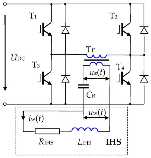
Figure 3.
Diagram of the high-current part of a bridge-type voltage inverter with serial resonance cooperating with an induction heating system (IHS).
Assuming ideal valves, inverter operation with full valve control limited only by TM dead time, and with an inductive load (work pulsation ω is greater than its own pulsation ω0), the time course for the current iw(t) of the IHS can be described by the relationship:
where
and
The current waveform in the inductor described by Equation (4) is in the form of an exponentially suppressed sine wave. This function exhibits oblique symmetry with respect to the time axis and has only odd harmonics in the Fourier series distribution. The harmonic amplitudes depend on the parameter b, and therefore indirectly on the TM dead-time value and the quality factor Q of the IHS. For typical induction heating values of Q > 4, the inductor current has a relatively small proportion of higher harmonics (the third harmonic is a few percent of the basic harmonic), which opens the possibility of conducting reliable calculations for the electromagnetic field of the IHS only in the case of the first harmonic of current. The value of first harmonic pulsation can be determined (Equation (8)) on the basis of its own pulsation (Equation (6)) and the b-factor, which value can be obtained [17] by the iterative solution of the equation:
Assuming the harmonic current of the inductor, the electromagnetic field of the IHS can be found based on Maxwell Equations [18], transformed into the form:
where A is the magnetic vector potential, J is the current density, μ is the magnetic permeability, and γ is the conductivity.
This equation is coupled with the Fourier–Kirchhoff Equation [19] taking into account the relevant boundary conditions and the initial condition.
It should be noted that the assumption of a sinusoidal electromagnetic field applies to both electric and magnetic fields, and can only be valid in magnetically linear environments. In the considered case, the magnetic non-linear material (steel) used as the charge contradicts this assumption. Such contradiction could be mitigated to an extent by using modified, substitute magnetizing curves B(H) in the calculations [20].
The method of solving the double-coupled field-circuit problem presented above can be described by the general calculation algorithm presented in Figure 4.
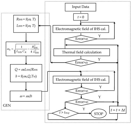
Figure 4.
General coupling algorithm for electromagnetic and thermal calculations, taking into account interaction between the IHS and power source.
To solve the field part, a commercial Flux program based on Finite Element Method (FEM) was used. This was embedded by the Application Programming Interface (API) in our own program, to modify the operating parameters of the resonance inverter in cooperation with various types of resonance systems. In this way, source–load cooperation was analyzed in the case of a ferromagnetic steel charge heated in a cylindrical IHS (Figure 5). Two representative cases of periodic heating were considered, for differently sized inductor-charge air gaps: a variant with a “large” s = 12.5 mm gap (d = 40 mm) and a variant with a “small” s = 2 mm gap (d = 61mm). This change had a significant impact on the value of the IHS quality factor, Q. A software packet based on the algorithm in Figure 4 was used to analyze the heating of the charge from an AC source with constant voltage amplitude Uz (corresponding to a constant DC supply voltage form the inverter).
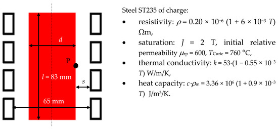
Figure 5.
Example of an IHS with a four-turn inductor.
Taking into account the source–load interaction, the heating process was analyzed in the cases of serial resonance, parallel resonance, and the LLC system (Figure 6). The values for the voltage Uz and capacity CR of the resonance system were selected so that in the “cold” state of each system the resonant frequency (equal to the operating frequency) was f = 30 kHz, while the power supplied to the IHS was P = 30 kW for a system with a “large” air gap and P = 45 kW for a system with a “small” gap.
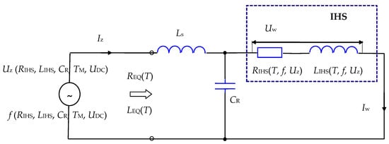
Figure 6.
Source co-operation with a non-linear load for the LLC resonance system.
Despite the fact that the output parameters of the power supply were the same in the “cold” state of the charge, the speed of the heating process in each of the three resonance systems was different. This was due to variations in power consumption from the source during the heating process.
Figure 7 compares the changes in REQ as a function of temperature at the midpoint P of the charge (Figure 5), for each of the three resonance systems on a relative scale in relation to the resistance REQ, cool that was found for the “cold” state of the charge. The relative changes in REQ are usually different in nature in the LLC system compared to the systems with serial or parallel resonance, but the range of changes may be larger or smaller. It can be concluded that from the point of view of energy matching this system is neutral in comparison to basic systems with serial or parallel resonance.

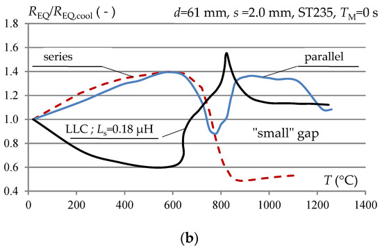
Figure 7.
Comparison of relative changes in resonance equivalent resistance of the load as a function of the charge surface temperature during heating by an inverter with different types of resonance system: (a) “large” gap and (b) “small” inductor–charge gap.
The use of an LLC system to perform energy matching during the induction heating process is however possible, if it can be carried out in a controlled manner, taking into account the change in the inductance value Ls.
A simulation of such a heating process is shown in Figure 8 for the IHS from Figure 5 with a “large” (s = 12.5 mm) inductor–charge air gap.
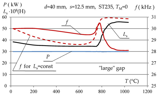
Figure 8.
Changes in series inductance Ls for the LLC inverter to maintain constant energy matching during the heating process, in the case of a system with a “large” inductor–charge gap.
As shown in Figure 8, the changes in inductance Ls required to maintain a constant equivalent resonance resistance REQ (constant power P) did not exceed 50% of the initial value. Such a range of choke inductance changes did not constitute a technical limitation of its feasibility. The changes in resonance frequency f also did not differ significantly from the natural changes (Figure 8) in the resonance frequency during the process of heating the charge.
3. LLC Setup in the Source–Load Energy Matching System
The resistance transformation coefficient pR in an LLC system with specific parameters depends on the operating frequency f (which is similar in resonance sources to the resonance frequency). With changing IHS parameters (and fixed values for the DC supply voltage and the ratio of the matching transformer), maintaining the required degree of energy matching usually requires modifying both the resonance capacity CR and the series inductance Ls. This is due to the fact that changes in the IHS parameters cause changes in the frequency, but at the same time the value of the operating frequency is related to technological requirements and cannot be changed arbitrarily. However, with relatively small changes in IHS resistance (reaching several times the value change) this adaptation can be accomplished by changing the value of series inductance Ls only, as long as this change is correlated with the load identification procedures and a corresponding change in the switching frequency of the inverter valves. It is advisable that the implementation of such a complex technical operation can be carried out for the widest possible range of changes in the load parameters, without undue user intervention. The technical possibility of regulating series inductance Ls is the main reason for limiting the range of load value changes for which it is possible to achieve energy matching with the inverter. This means that at the source design stage the anticipated range of load changes and the permissible operating frequency range should be known, which requires the appropriate selection of both resonant capacitor banks and a matching transformer ratio, which (at a fixed DC voltage supplying the inverter) determines the expected value of the equivalent resonance resistance REQ of the load. This must be less than the maximum obtainable equivalent resistance REQ,max, as discussed above.
For a specified IHS (RIHS i LIHS), the value of resonance capacity CR can be preselected to obtain the expected value of REQ at a certain preadopted operating frequency f (ω = 2πf)) (if this is not possible, then the frequency at which one expects the desired resistance to be reached can be increased) according to the relationship [21]:
where
In the LLC inverter, the expected value of REQ should be obtained in a resonance (or near resonance) state. Therefore, with the selected value of CR capacity (and known RIHS and LIHS values) the initial value for series inductance Ls should be determined. This can be achieved in two steps by:
- Calculation of the frequency value fr,u, at which the desired REQ value occurs, from the relationship [21]where
- Calculation of the series inductance Ls value, which ensures the resonance state at a frequency above fr,u [21]:
It should also be noted that the value for REQ obtained at a given frequency fr,u is significantly influenced by the value of the selected resonant capacity CR. By reducing CR (and simultaneously increasing the value of series inductance Ls), it is possible to increase to a certain extent the maximum value of the resistance REQ,max obtainable in the resonance state, without a significant change in the value of the resonance frequency itself.
In order to reduce losses, ensure a compact design, and facilitate easy self-regulation by the source of the Ls inductance value, it is advisable for the separating transformer and the series choke to be one magnetic module, functioning as an autotransformer with galvanic separation. Figure 9 shows the structure of the developed solution, which was used in the constructed 30 kW generator model. The secondary winding of the transformer and the series choke Ls are a single element. The range of variation in Ls easily exceeds the value of Ls,max/Ls,min/ > 3.5 (Ls,min/Ls,max/ < 0.28). Using e.g., the SM 57/76-2864A hybrid stepper motor with the 1.8° angle of adjustment, this can be achieved by making 7 turns, which for a pulse frequency of 300 Hz requires approximately 7 s. Thus a change in inductance by 50% can be made in approximately 1.3 s.
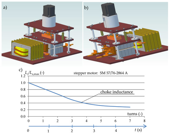
Figure 9.
Structural model of the magnetic assembly with a stepper motor: (a) view from the transformer side, (b) view from the choke side, and (c) choke inductance change as a function of stepper motor turns.
By properly controlling the inductance values Ls and the frequency of the inverter, it is possible for the power source to automatically correct the equivalent load impedance (Figure 8). To this end, the source should be equipped with both measuring systems, to enable identification of the IHS parameters (including during the heating process of the charge) and microprocessor-controlled output systems, which determine the values of inductance Ls and operating frequency.
4. Resonant Generator with Controlled LLC System
The application of the controlled LLC system has repercussions for the generator control system, especially the power control system [22]. On one hand, it creates new regulation capabilities (Ls), but at the same time it introduces new limitations, resulting from both the speed of the temperature changes that occur during induction heating (which affect the electrical parameters) and the mechanical and regulatory choke Ls capabilities. Bearing in mind the issue of energy matching in the implemented generator model, three independent inverter modules were used. This solution allowed the impedance source–load matching capabilities to be extended, by changing the configuration of the modules from serial to parallel and vice versa. In each module, it is possible to independently regulate the value of series inductance Ls via a system controlled by stepper motors. The inverters work on a common circuit of the IHS and resonant capacitor CR. Figure 10 shows a simplified diagram of the generator solution used, including only one inverter module.
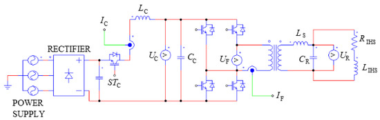
Figure 10.
Simplified schematic diagram of the LLC generator system, including only one inverter module.
The tasks of the control system can be generally divided into those implemented before the start of the heating process and those implemented during the heating process. The first group of tasks performs the function of specific identification both of the load and the current state of the generator settings, for example the value of the resonance capacitor bank. The second group is responsible for the actual implementation of the generator control, including maintenance of the state of resonance and control of the power supplied to the IHS, as well as for the correction of energy matching by changing the choke value Ls (this method of regulation should be limited, however, due to the mechanical systems used). A distributed control system, whereby a separate function was assigned to each element of the system, allowed us to differentiate between the “outer” and “inner” parts of the control system (Figure 11).

Figure 11.
Schematic diagram of the generator control distributed structure.
The “outer” part is the master computer, via which the operator communicates with the system, using its Human Machine Interface (HMI). The master computer is used to set the heating process parameters—in the form of two quantities, the heating power and the frequency of the inverter—within the permissible range of deviation, which is based on technological process requirements known to the operator. The executive system performs tests in a frequency range from 10 to 100 kHz to determine the actual state of the system, and the computer program selects values of four basic parameters providing the best fit to the connected IHS, i.e., the resonance frequency, series inductance Ls, the configuration of the three connected inverters, and the value of the resonant capacitor CR. The computer application also allows, in a predictive way, to take into account the probable changes in system impedance caused by the changing temperature of the heated charge [23].
The “inner” part of the control system is the motherboard, on which are located the FPGA system (with the structure shown in Figure 12), as well as 12 A/D converters and an ARM type processor that directly controls the operation of the executive system.
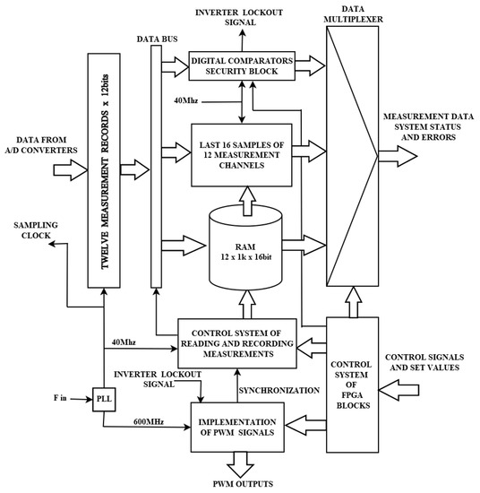
Figure 12.
Block diagram of the FPGA structure.
The executive system consists of three inverter blocks, the matching system, and a power supply. A fast Infineon processor based on the ARM Cortex-M4 core performs the tasks of the control algorithm, exchanging information with the master computer system, the I/O module system, and the programmable logic system. It also controls the inverter valves and stepper motors that regulate the inductance Ls values. The need for simultaneous measurement and the processing of many analog signals (such as output voltage, output current, and intermediate circuit current, as well as the resonant capacitor voltage) in real time creates serious challenges for each of the inverter blocks. Most of the measured signals are AC signals, which require a high sampling frequency and the collection of large amounts of data. Therefore, this function is implemented by means of an FPGA programmable logic system (Figure 12), using analog-to-digital converters with a sampling frequency of 40 MHz. The FPGA also implements procedures responsible for fast PWM outputs, which control the voltage inverters in a wide frequency range. The internal PLL system, the programmable structure of which enables the implementation of a fill factor with a time step of 1.66 ns, allows for smooth setting of the inverter frequency. The PLL system also provides rapid handling of errors and protects the inverter valves from exceeding the range of acceptable values for signals.
One of the elements of the structure is an automat that controls the recording of measurement data to the internal RAM memory of the FPGA system. This was developed so that data could be recorded with a time interval defined as 1/64 (n = 64) of the PWM signal period fed to the voltage inverters. This allows 16 full periods to be recorded for each of the measured analog signals. The collected data are then sent to the ARM microprocessor controller, which estimates the amplitude values of the first harmonic of the signals and the phase shifts between them. This task is accomplished by searching, by the method of least squares, the sinusoidal wave that best matches the set of measurement data (vector Y). This method can be reduced to solving the matrix relationship [24]:
in which
where Δθ is the sampling period in the angular domain.
The two-element vector B contains coefficients B1, B2, minimizing the mean square error for the function:
where B and ϕ are the amplitude and phase of the approximated sinusoid, respectively.
This method was used to estimate the phase shift between the current and voltage of the inverter, while implementing the resonance search algorithm in the system. The saved data set also allows for ongoing estimation of the active power PF supplied to the IHS from each inverter system separately. The active power PF is calculated based on the sum of the products of the instantaneous values of the inverter output voltage uF and the inverter current iF (Figure 10), for one full PWM signal period:
It is thereby possible to determine the power when the system is near resonance. In a situation in which the phase shifts between the voltage and current are large and at low signal amplitudes, estimating power based on Equation (19) can lead to large relative errors, due to inaccuracies associated with the determination of signal phases. In such cases, it is better to estimate the PF power based on measurement of the signals supplying the UC and IC inverter (Figure 10), taking into account the losses in the inverter:
The FPGA system also implements an averaging module of 16 measurement samples, which is especially useful for reading DC signal values.
5. Cascade Power Control System
The functions described above enable the implementation of the control algorithm, the main purposes of which are to control the power supplied to the IHS, while maintaining the system in resonance, and changing the energy match (but only when necessary). The proposed cascade regulator of the generator control is shown in Figure 13.
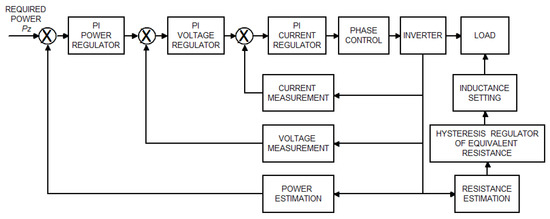
Figure 13.
Block diagram of the cascade power regulator in the induction heating generator model.
Its basic components are:
- PI regulator of power, which based on the difference between PZ set power and realized power determines the set voltage UC for the DC circuit (Figure 10) of the inverters;
- PI regulator of voltage UC for the DC inverter circuit, which on the basis of the DC set voltage error and the actual voltage determines the set current IC for the input circuit of the inverter;
- PI regulator of the set current IC for the input circuit with correction from the DC voltage UC of the inverter, which (based on the current error) determines the PWM system of the STC transistor (Figure 10), which controls the DC current IC of the input choke.
A hysteresis-type regulator of REQ equivalent resistance implementing energy matching was added to the control system. This regulator is designed to maintain the REQ value at a level close to the rating resistance, but only when it is necessary to ensure work with the required power. The control system decides to change the Ls series inductance settings when the DC voltages UC supplying the inverter exceed 90% of the rated value (decrease in Ls value) or the DC current IC supplying the inverter exceeds 90% of the rated value (increase in Ls value). Considering the times of sending instantaneous data to the processor from 12 measurement channels, without using a fast parallel bus, it was initially assumed that the regulator procedure would be called every 1 ms.
6. Experimental Testing
The experimental tests of the generator model with a controllable LLC system included heating a cylindrical ST235 steel charge with a diameter of 30 mm in a 50 mm diameter inductor (which can be considered as heating with a “large” air gap). Heating was carried out with a power of around 15 kW to a temperature of 850 °C (i.e., above the Curie point of magnetic transformation). A photograph of the test stand is shown in Figure 14.
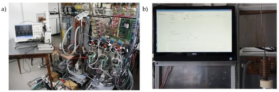
Figure 14.
Photograph of the model of the generator for induction heating with a controlled LLC system: (a) back side and (b) front side.
We investigated the effectiveness of the initial impedance matching procedure, by conducting load identification tests before the start of the heating process, as well as the behavior of the cascade controller during the heating process. Figure 15 shows the actual power waveforms of the source during the heating process.
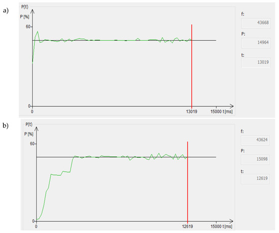
Figure 15.
Visualization of the generator power waveform during the heating process: (a) with the initial load identification procedure and (b) with a starting frequency that differs by 5% from that established in the load identification procedure.
Figure 15a shows the power waveforms obtained when the heating process was preceded by a load identification test, leading to the initial selection of both the inductance value Ls and the resonance frequency. A small change in the value (by 5%) of the starting frequency compared to that obtained by means of an identification test (Figure 15b) caused a significant increase in the duration of power stabilization at the desired level. Performing the load identification procedure just before the actual heating process begins allowed heating at full power from the beginning of the process. Otherwise, the system first looked for resonance and was only then able to increase the power supplied to the charge. The waveforms also show that the assumed calling of the regulating procedure every 1 ms ensured correct control of the heating process only during the initial phase, before any significant changes occurred in the load parameters. At a later stage of the process, when the system parameters began to change dynamically, the regulator was unable to maintain the set power, leading to the power oscillations of several percent we observed. Analysis indicates that eliminating the oscillations required at least a fourfold increase (to 4 kHz, so 0.25 ms) in the frequency of calling the regulating procedure.
Our research fully confirmed the advantages of the controlled LLC system used, which makes it possible to regulate source–load energy matching. Figure 16 shows the waveforms for current (yellow) and inverter output voltage (green), taken experimentally for one inverter module during the heating process. Figure 16a shows the current and voltage waveforms for the inverter module with the impedance matching procedure switched on (by inductance regulation Ls), and Figure 16b the waveforms for the inverter module without this procedure.
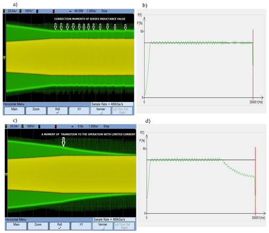
Figure 16.
Current, output voltage and power waveforms for one module of the generator inverter during the heating process: (a,b) with Ls the change procedure enabled and (c,d) without changing the Ls settings.
Having the ferromagnetic steel ST235 charge, the equivalent resistance REQ of the IHS (see Figure 7a for the “large” air gap) decreased significantly at the temperature above the Curie point. Heating the charge with the required constant power caused an increase in the current amplitude and a decrease of the inverter voltage amplitude. With Ls control (Figure 16a), after reaching 90% of the maximum current value the system began to correct the Ls settings to stop the REQ decreasing. This allowed the voltage value (and therefore the set power, Figure 16b) to be maintained without exceeding the permissible current value. The points at which correction of the series inductance value begins are indicated by white arrows in Figure 16a. If it is not possible to correct the Ls settings (Figure 16c), once 90% of the current value has been reached the system supplies the set power until the maximum current value is reached (this moment is marked by a white arrow in Figure 16c). Then the regulator enters the current limit so that further decreasing of the REQ value causes the inverter voltage decrease, which reduces the value of the supplied power, Figure 16d.
7. Summary and Conclusions
One of the weaknesses of the use of induction heating technology, being an important form of energy conversion in industrial processes, is its low ability to adapt to different types of heated charges. This also applies to the issue of energy matching, which can place significant restrictions on the realistically available source power, which falls well below the rated power. By effective use of the possibilities provided by an LLC resonance system, this situation can be significantly improved, optimizing automatically the heating system parameters. An LLC system with controlled series inductance Ls in combination with measurement and load identification algorithms enables the realization of a self-acting energy matching system. Due to the programmable FPGA control system the proposed solution induced only a few percent increase in investment costs of the generator but as a result it allowed the control system to efficiently use the potentially available power for various types of IHS. Such a system can implement power control and adapt to changing load parameters, including during the heating process itself. The use of a cascade regulator allows preferential power control by changing the supply voltage, but at the same time permits effective energy matching if a change in the energy match is necessary to maintain power at the desired level. The presented experimental results indicate the large utility of the initial load identification procedure (especially in the case of frequent change of the type of heated charge). It allowed almost instantaneous heating with the full value of the desired power, which is particularly important in short-time fast induction heating processes. Our results show too that in rapid induction heating processes calling the power regulator procedure every 1 ms was not frequent enough, leading to noticeable power oscillations of several percent. Their eliminating requires at least a fourfold increase in the frequency of calling the regulating procedure.
8. Patent
Patent resulting from the work reported in this manuscript:
Kobos W.; Zgraja J. Tracking method of impedance matching system of inverter for induction heating and the inverter impedance matching system to induction heating. Patent number: PL 225064 B1, February 28, 2017.
Author Contributions
Conceptualization, J.Z.; Formal analysis, J.Z. and G.L.; Funding acquisition, J.Z.; Investigation, J.Z. and G.L.; Methodology, J.Z. and G.L.; Project administration, J.Z.; Software, J.Z. and J.K.; Supervision, J.Z.; Visualization, J.Z. and G.L.; Writing—original draft, J.Z.; Writing—review and editing, J.Z. and J.K. All authors have read and agreed to the published version of the manuscript.
Funding
This work was supported by the Polish National Centre for Research and Development NCBiR under Grant PBS1/A4/2/2012.
Conflicts of Interest
The authors declare no conflict of interest.
References
- Dede, E.J.; Jordan, J.; Esteve, V. State-of-the Art and Future Trends in Transistorised Inverters for Induction Heating Applications. In Proceedings of the 5th IEEE International Caracas Conference on Devices, Circuits and Systems, Punta Cana, Dominican Republic, 3–5 November 2004; pp. 204–210. [Google Scholar]
- Cesano, M.; Etflandrin, S.; Griffero, G.; Natale, L. Design Optimization of a High Frequency Power for Induction Heating Application Supply. In Proceedings of the International Symposium on Heating by Electromagnetic Sources HES-10, Padua, Italy, 19–21 May 2010; pp. 419–424. [Google Scholar]
- Zgraja, J. Susceptibility of the LLC Resonance Generator for Induction Heating on Changes in Load Parameters Caused by Heating the Charge. In Proceedings of the International Conference on Electrotechnology: Processes, Models, Control and Computer Science (EPMCCS), Kielce, Poland, 12–14 November 2018. [Google Scholar] [CrossRef]
- Cheng, X.; Miao, L.; Song, Y.; Su, Z.; Chen, H.; Chen, X.; Zhang, J.; Zhang, H. High efficiency power management and charge boosting strategy for a triboelectric nanogenerator. Nano Energy 2017, 38, 438–446. [Google Scholar] [CrossRef]
- Xu, S.X.; Ding, W.B.; Guo, H.Y.; Wang, X.H.; Wang, Z.L. Boost the performance of triboelectric nanogenerators through Circuit Oscillation. Adv. Energy Mater. 2019, 9, 1900772. [Google Scholar] [CrossRef]
- Espi, J.M.; Dede, E.J.; Ferreres, A.; Garcia, R. Steady State Frequency Analysis of the LLC Resonant Inverter for Induction Heating. In Proceedings of the IEEE 1996 CIEP, Cuernavaca, Mexico, 14–17 October 1996; pp. 14–17. [Google Scholar] [CrossRef]
- Jingang, L.; Yanru, Z.; Yang, Z. Study on Static Electricity Induction Load-matched of Voltage-Source Converter for induction Heating. In Proceedings of the 31st Annual Conference of IEEE Industrial Electronics Society, Raleigh, NC, USA, 6–10 November 2005; pp. 1284–1287. [Google Scholar]
- Gao, Z.; Zhou, Y. Research on Switching Losses for Induction Heating Power Supply with LLC Resonant Load. In Proceedings of the 2011 International Conference on Electronic & Mechanical Engineering and Information Technology, Harbin, China, 12–14 August 2011; Volume 5, pp. 2474–2477. [Google Scholar]
- Lucía, O.; Maussion, P.; Dede, E.J.; Burdío, J.M. Induction Heating Technology and Its Applications: Past Developments, Current Technology, and Future Challenges. IEEE Trans. Ind. Electron. 2014, 61, 2509–2520. [Google Scholar] [CrossRef]
- Wang, R.; Wu, Y.; He, G.; Lv, Y.; Du, J.; Li, Y. Impedance modeling and stability analysis for cascade system of three-phase PWM rectifier and LLC resonant converter. Energies 2018, 11, 3050. [Google Scholar] [CrossRef]
- Zhang, Z.J.; Bergmann, N.W. Analysis and Design of LCCL Load Matching Circuit for High-Frequency Induction Heating Series Resonant Inverter. Int. Rev. Electr. Eng. 2012, 7, 5392–5399. [Google Scholar]
- Zgraja, J. Dual-frequency induction heating generator with adjustable impedance matching. IEEE Trans. Ind. Electron. 2019, 66, 8308–83173. [Google Scholar] [CrossRef]
- Espi Huerta, J.M.; Dede, E.J.; Garcia Gil, R.; Castello Moreno, J. Design of the L-LC resonant inverter for induction heating based on its equivalent SRI. IEEE Trans. Ind. Electron. 2007, 54, 3178–3187. [Google Scholar] [CrossRef]
- Chudjuarjeen, S.; Sangswang, A.; Koompai, C. An improved LLC resonant inverter for induction heating with asymmetrical control. In Proceedings of the IEEE International Symposium on Industrial Electronics, Seoul, Korea, 5–8 July 2009. [Google Scholar] [CrossRef]
- Khemakhem, A.Z.; Kourda, F. An improved LLC resonant inverter for induction heating applications. In Proceedings of the International Conference on Electrical Sciences and Technologies in Maghreb (CISTEM), Tunis, Tunisia, 3–6 November 2014. [Google Scholar] [CrossRef]
- Khemakhem, A.Z.; Belloumi, H.; Kourda, F. An Improved Transformer for LLC Resonant Inverter for Induction Heating Applications. Int. J. Adv. Comput. Sci. Appl. 2016, 7, 476–483. [Google Scholar]
- Zgraja, J.; Bereza, J. Computer simulation of induction heating system with series inverter. COMPEL 2003, 22, 48–57. [Google Scholar] [CrossRef]
- Rudnev, V.; Loveless, D.; Cook, R.L.; Black, M. Handbook of Induction Heating; CRC Press: Boca Raton, FL, USA, 2002. [Google Scholar]
- Holman, J.P. Heat Transfer; McGraw-Hill: New York, NY, USA, 2002. [Google Scholar]
- Labridis, D.; Dokopoulos, P. Calculation of eddy current losses in nonlinear ferromagnetic materials. IEEE Trans. Magn. 1989, 25, 2665–2669. [Google Scholar] [CrossRef]
- Kobos, W. Active Impedance Matching of the Load of Inverter Generators for Single and Dual Frequency Induction Heating. Ph.D. Thesis, Lodz University of Technology, Łódź, Poland, 2017. [Google Scholar]
- Esteve, V.; Jordán, J.; Sanchis-Kilders, E.; Dede, E.J.; Maset, E.; Ejea, J.B.; Ferreres, A. Enhanced Pulse-Density-Modulated Power Control for High-Frequency Induction Heating Inverters. IEEE Trans. Ind. Electron. 2015, 62, 6905–6914. [Google Scholar] [CrossRef]
- Zgraja, J.; Urbanek, P.; Kucharski, J. Predictive method of improvement of the generators rated power usage in inductive heating. In Proceedings of the International Conference on Electromagnetic Devices and Processes in Environment Protection with Seminar Applications of Superconductors (ELMECO & AoS), Lublin, Poland, 3–6 December 2017. [Google Scholar] [CrossRef]
- Debowski, A.; Chudzik, P. An adaptive method of averaging the space vectors location in DSP controlled drives. In Proceedings of the ICEM 2000: International conference on electrical machines, Espoo, Finland, 28–30 August 2000; pp. 913–917. [Google Scholar]


© 2020 by the authors. Licensee MDPI, Basel, Switzerland. This article is an open access article distributed under the terms and conditions of the Creative Commons Attribution (CC BY) license (http://creativecommons.org/licenses/by/4.0/).