Dynamic and Adjustable New Pattern Four-Vector SVPWM Algorithm for Application in a Five-Phase Induction Motor

Abstract
1. Introduction
2. Five-Phase Induction Motor Components and Structural Characteristics
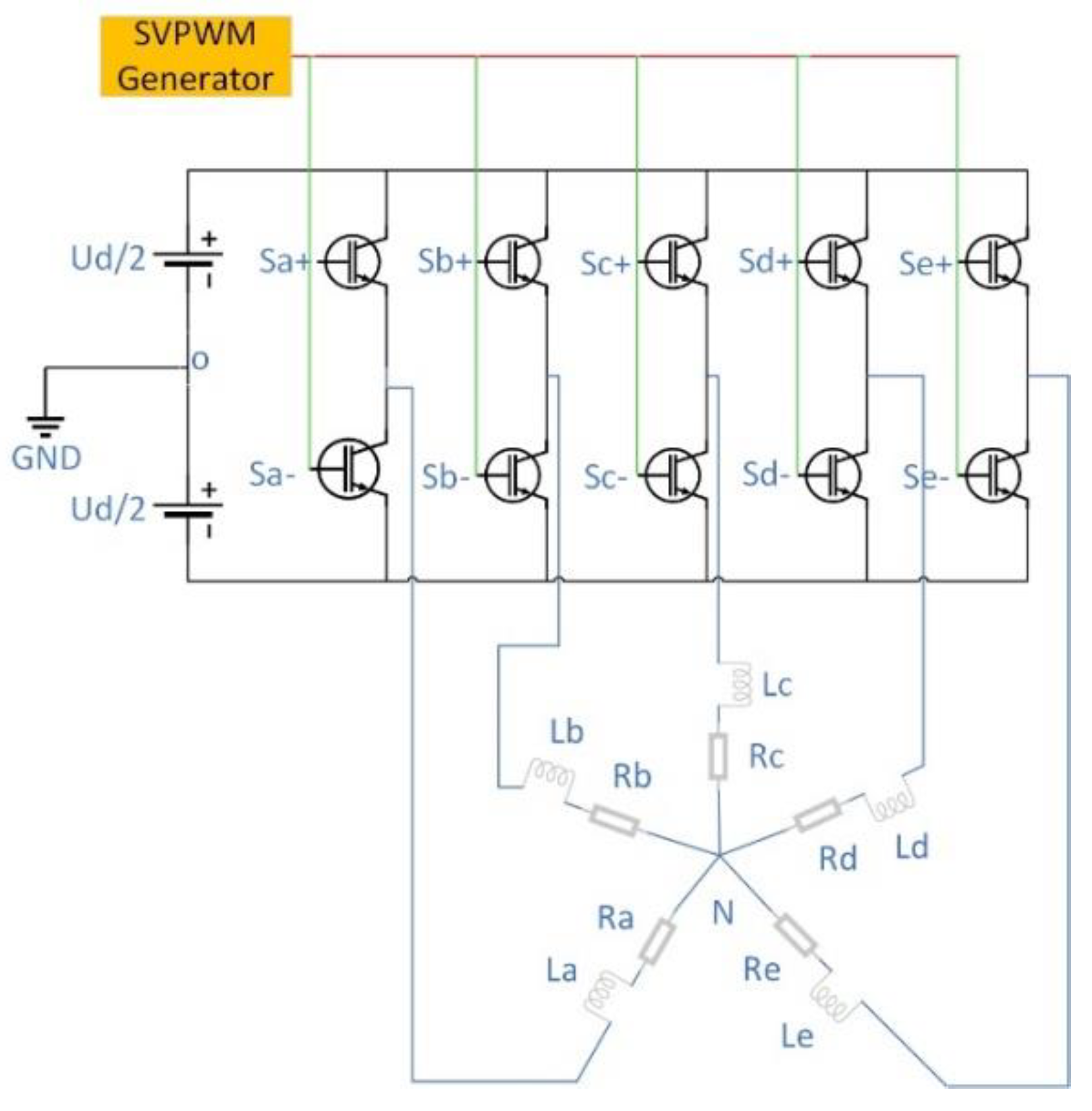
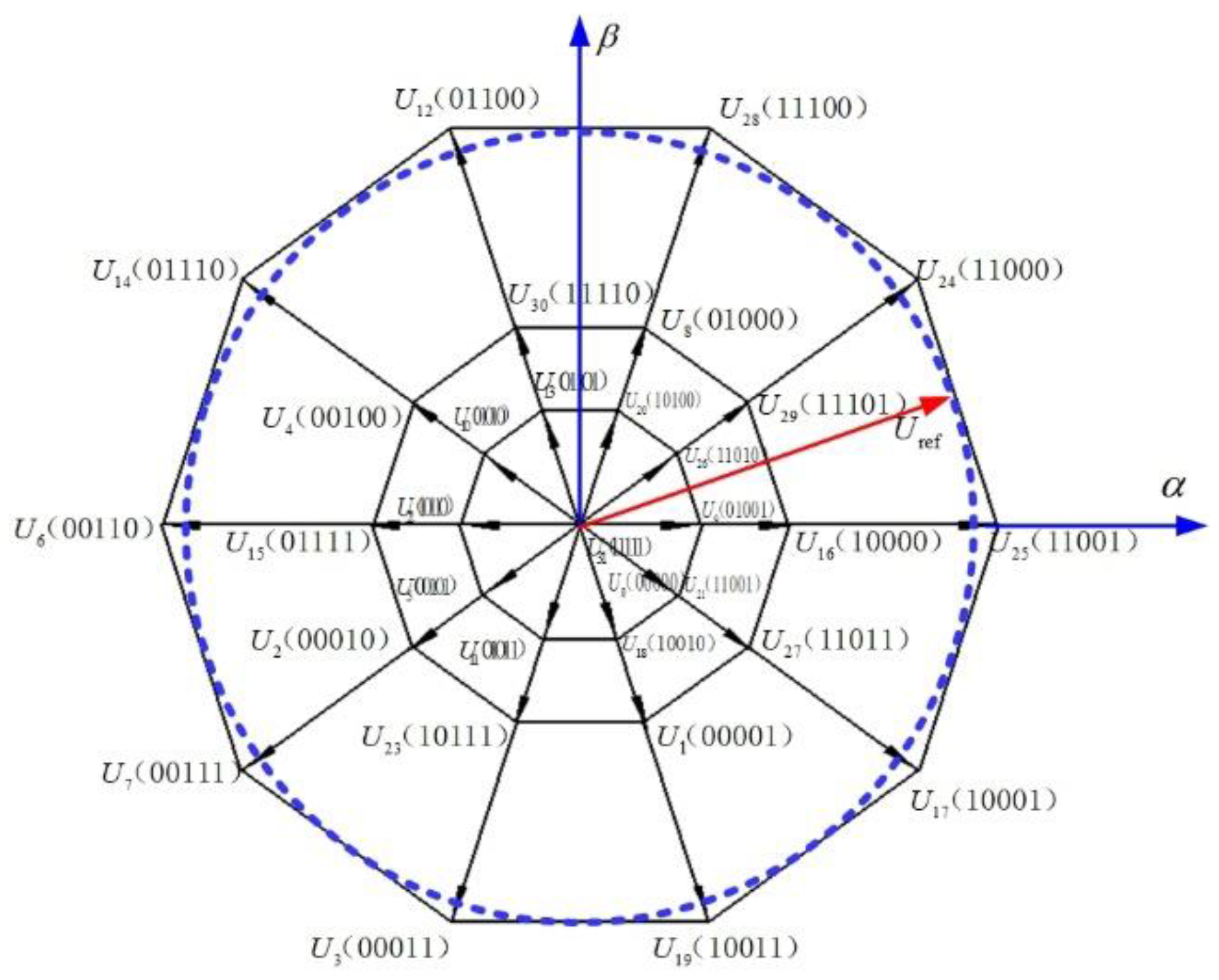
3. Analysis of a Space Voltage Vector Based on a Five-Phase Voltage Inverter
4. Algorithm Analysis and Comparison
4.1. Traditional Last Four-Vector Algorithm
- (1)
- An independent generation of the output voltage in the n-phase VISs requires at least (n − 1) active voltage vectors, where n is the number of phases.
- (2)
- NTSVPWM is a simple extension of space vector modulation of three-phase VSIs, which leads to the generation of low-order output voltage harmonics of significant values.
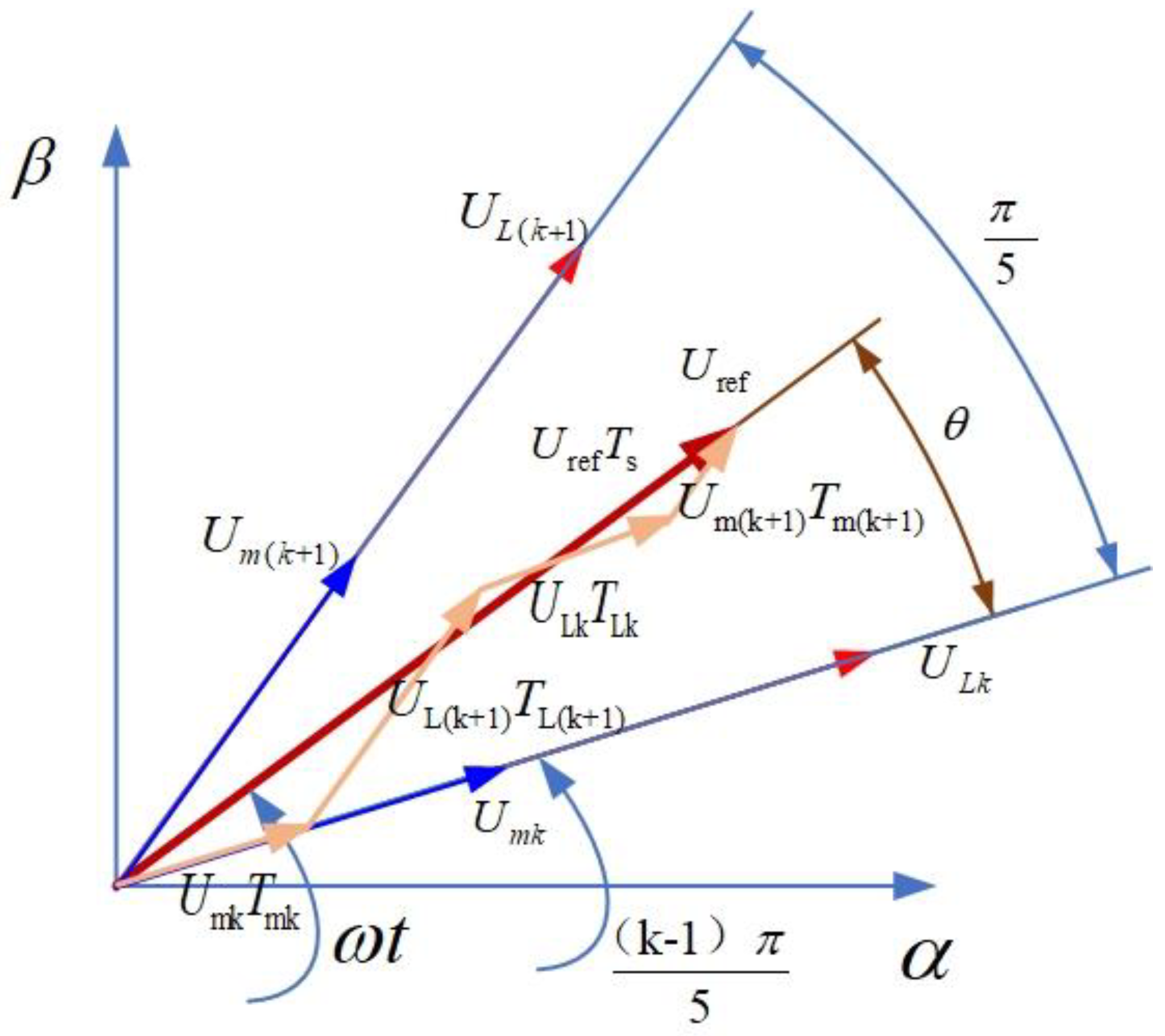
4.2. Dynamic Modulation Four-Vector Algorithm
- (1)
- Define the action time ratio λ between the medium vector and the large vector.
- (2)
- According to the volt-second balance principle and Equation (8), compute the action time of the space vector to give Equations (17)–(20):
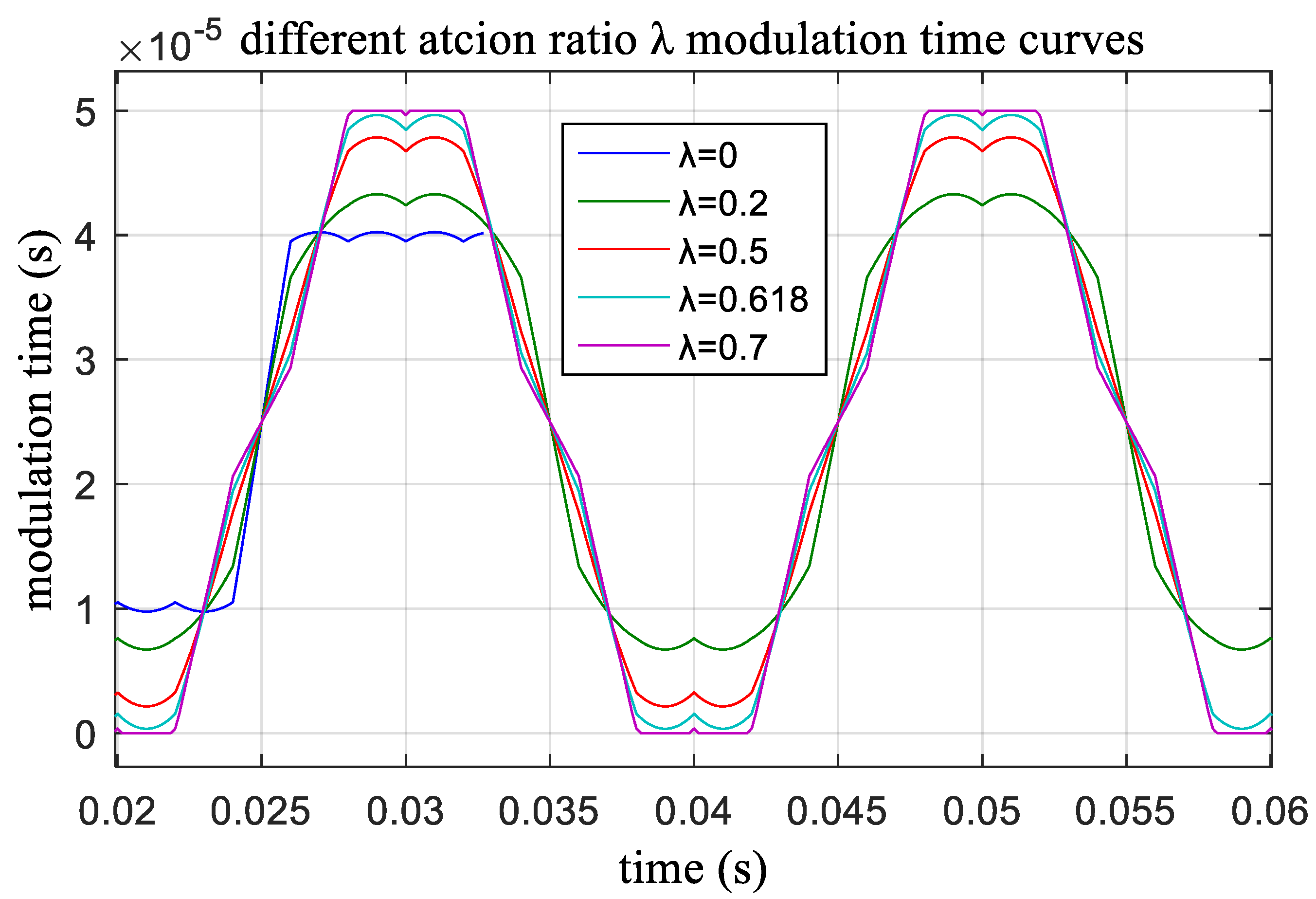
- (3)
- Determine the relationship between the parameter λ and the reference voltage Uref, which is shown as Equation (21):
- (4)
- Determine the relationship between action time ratio λ and the modulation index m to gain maximum utilization of the DC bus voltage, which is shown as Equation (22):
- (5)
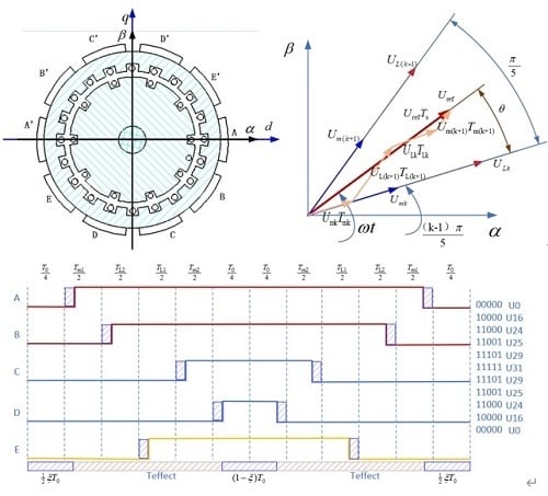
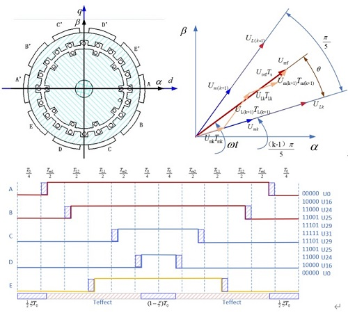
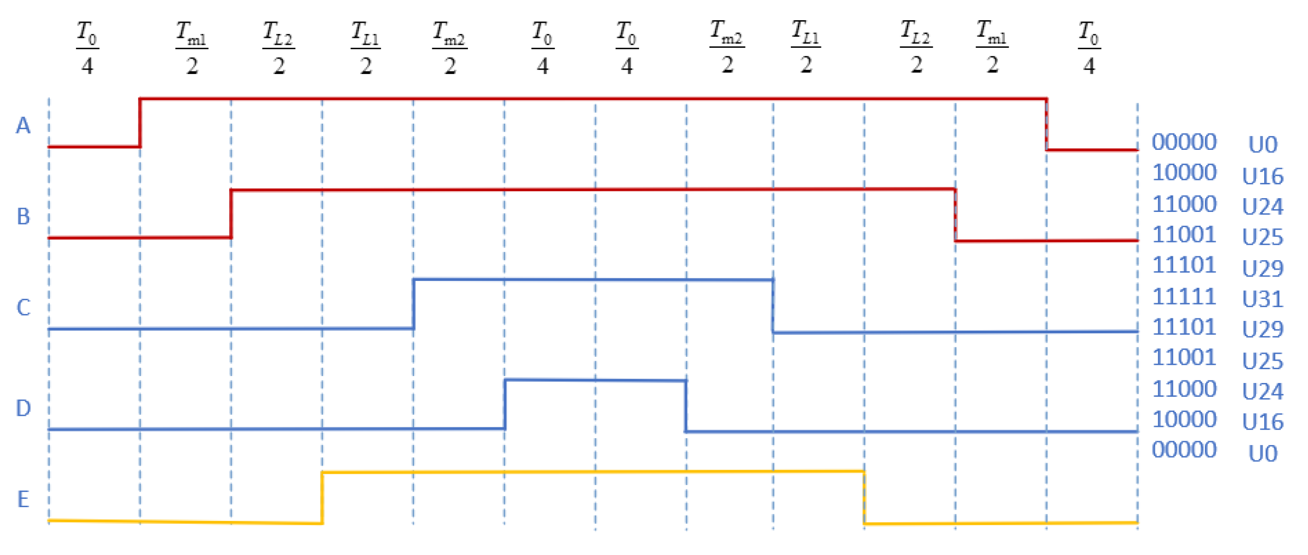
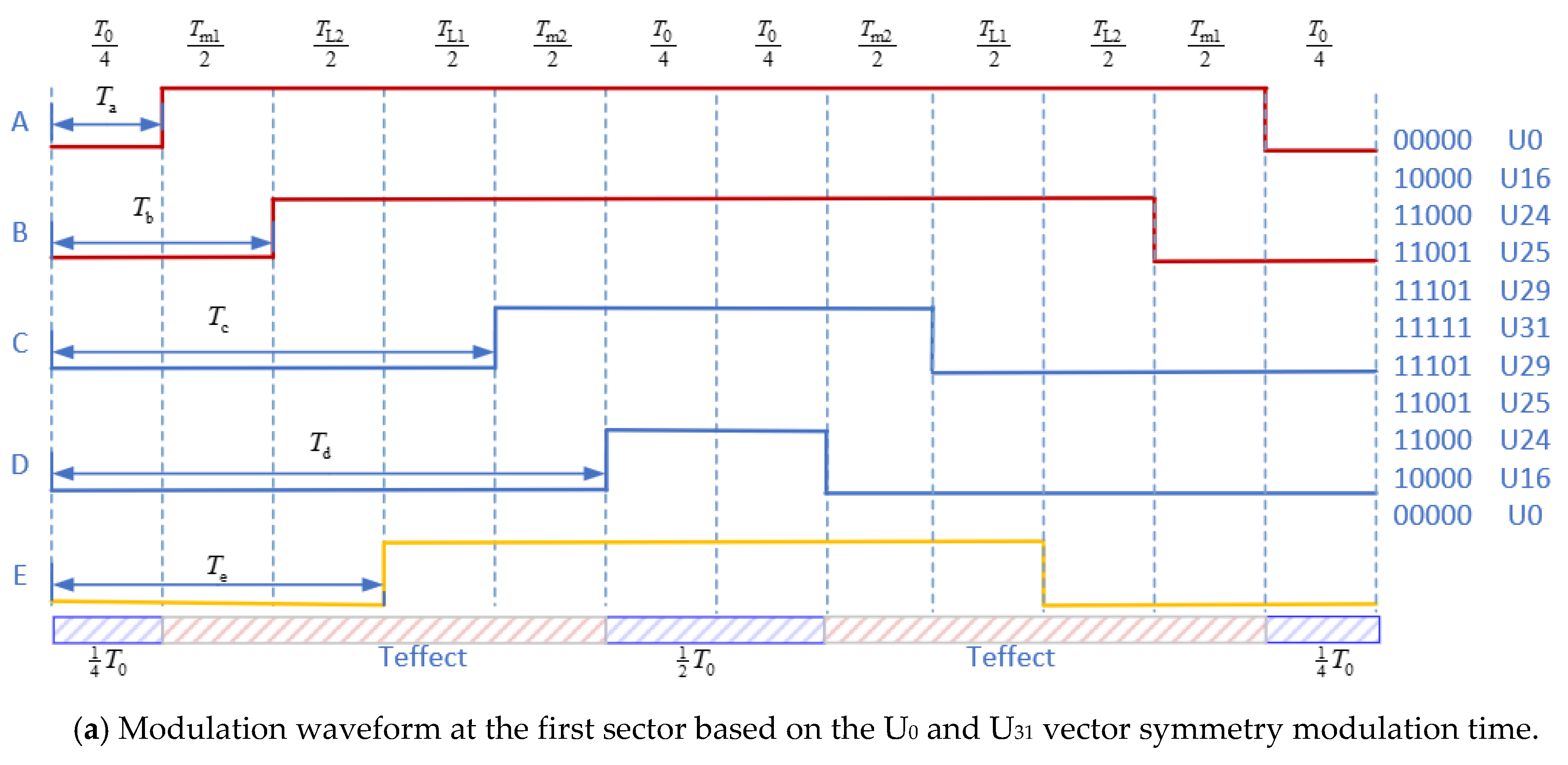
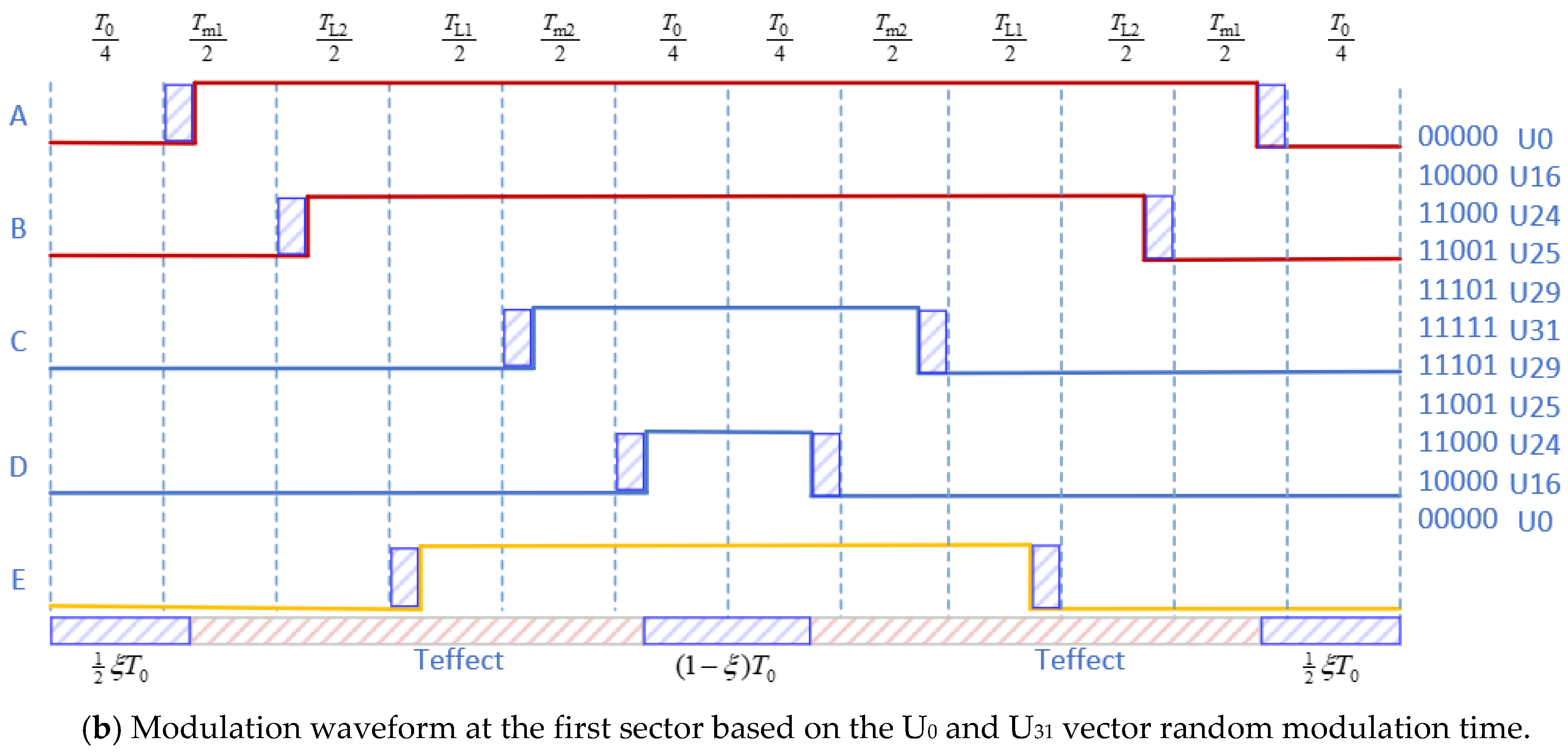
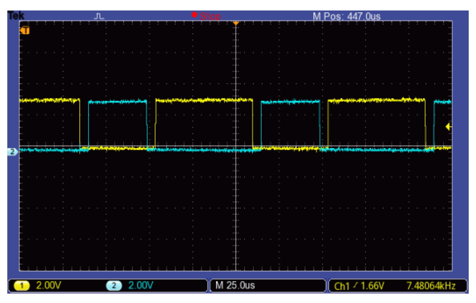
- Zero-vector action time randomizationThe zero-vector action time randomization was proposed because the MMF (magneto motive force) depends on the five-phase voltage vector action time difference and has nothing with the conduction time of the voltage vector. Zero-vector action time randomization, which can adjust the electromagnetic compatibility without additional hardware, was used to spread the harmonics concentrated around certain frequencies to a wider frequency band and produce a more continuous and uniform power spectrum. In order to keep Teffect, as defined in Equation (23), as a constant and to reduce the harmonic effect, zero-vector action time randomization was introduced.In Sector 1, for example, the principle of zero vector randomization is shown in Figure 8. Figure 8a shows the PWM symmetric modulation waveform adopting the traditional four-vector method, wherein the action time of the two zero vectors is equal. Figure 8b shows the PWM random modulation waveform, wherein the action time of the two zero vectors is random.
5. Simulation and Experiments
5.1. Simulation
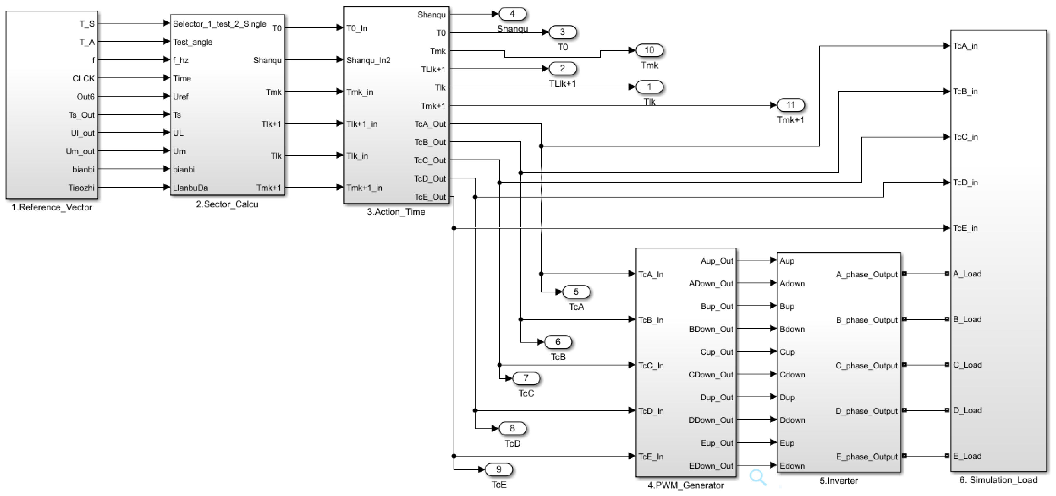
- (1)
- Reference-voltage module: This module was used to set the simulation parameters, such as the five-phase voltage, frequency, and modulation index, to compute the reference voltage.
- (2)
- Sector calculation module: This module was used to calculate the sector of the reference vector and the action time of the corresponding space vector.
- (3)
- Action time module: This module was used to determine the sequence of the space vector at every sector and the effect of moment of the space vector.
- (4)
- PWM generator module: This module was used to generate the PWM wave.
- (5)
- Inverter module: This module was used to simulate the characteristics of the five-phase voltage-source inverter.
- (6)
- Simulation-load module: This module was used to simulate the characteristics of the experimental induction motor.
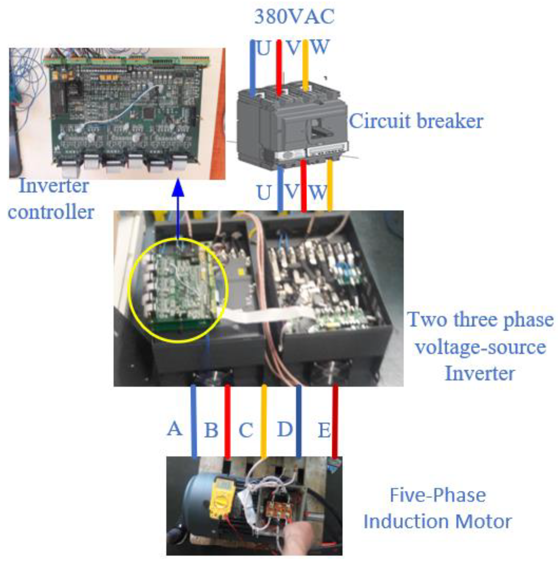
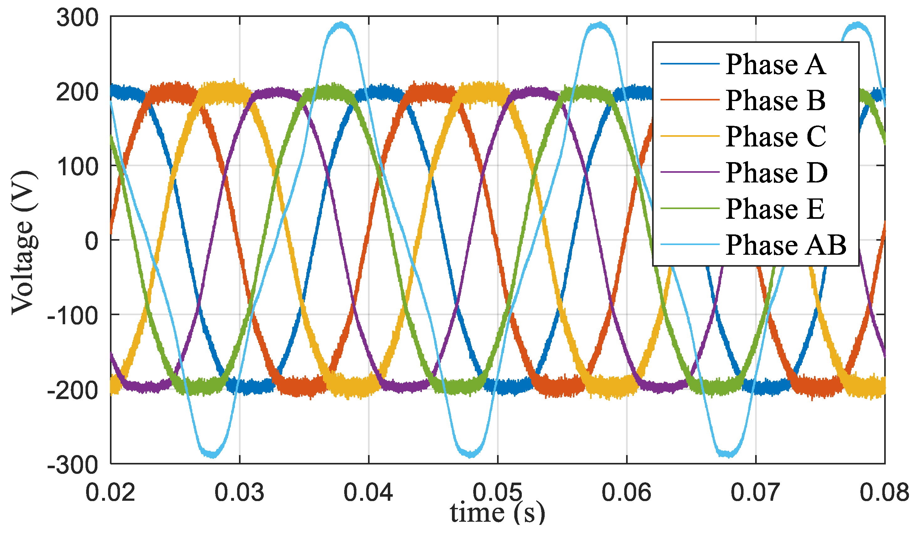
5.2. Experiments
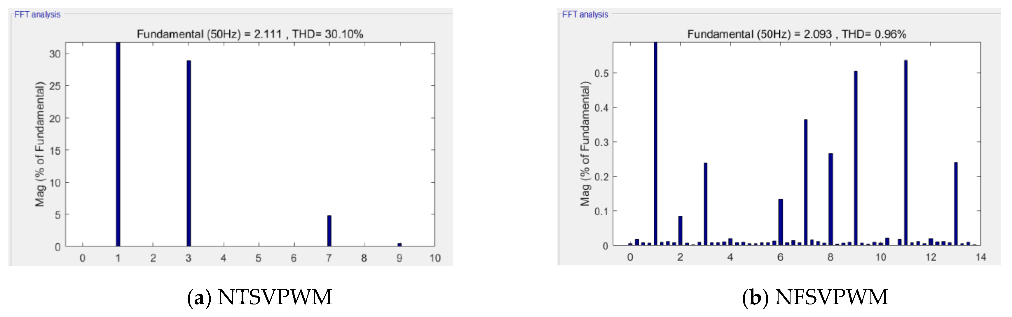
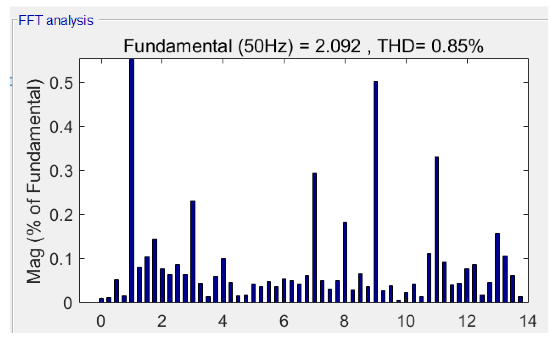
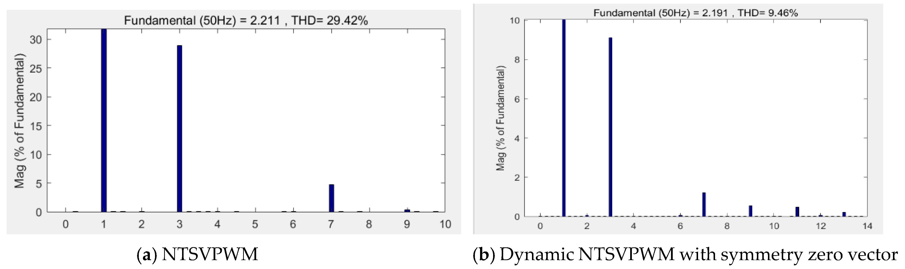
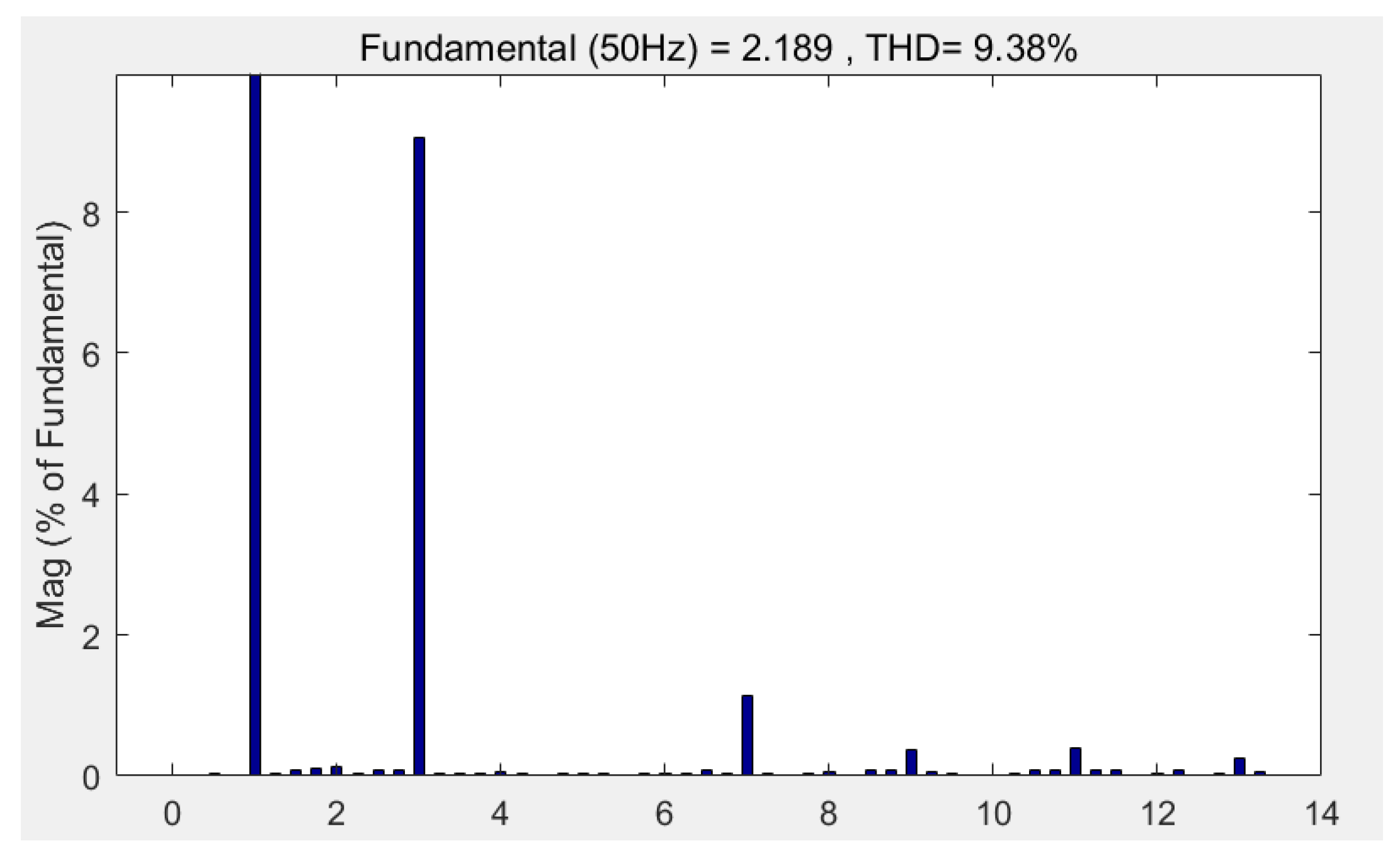
5.3. Results Analysis
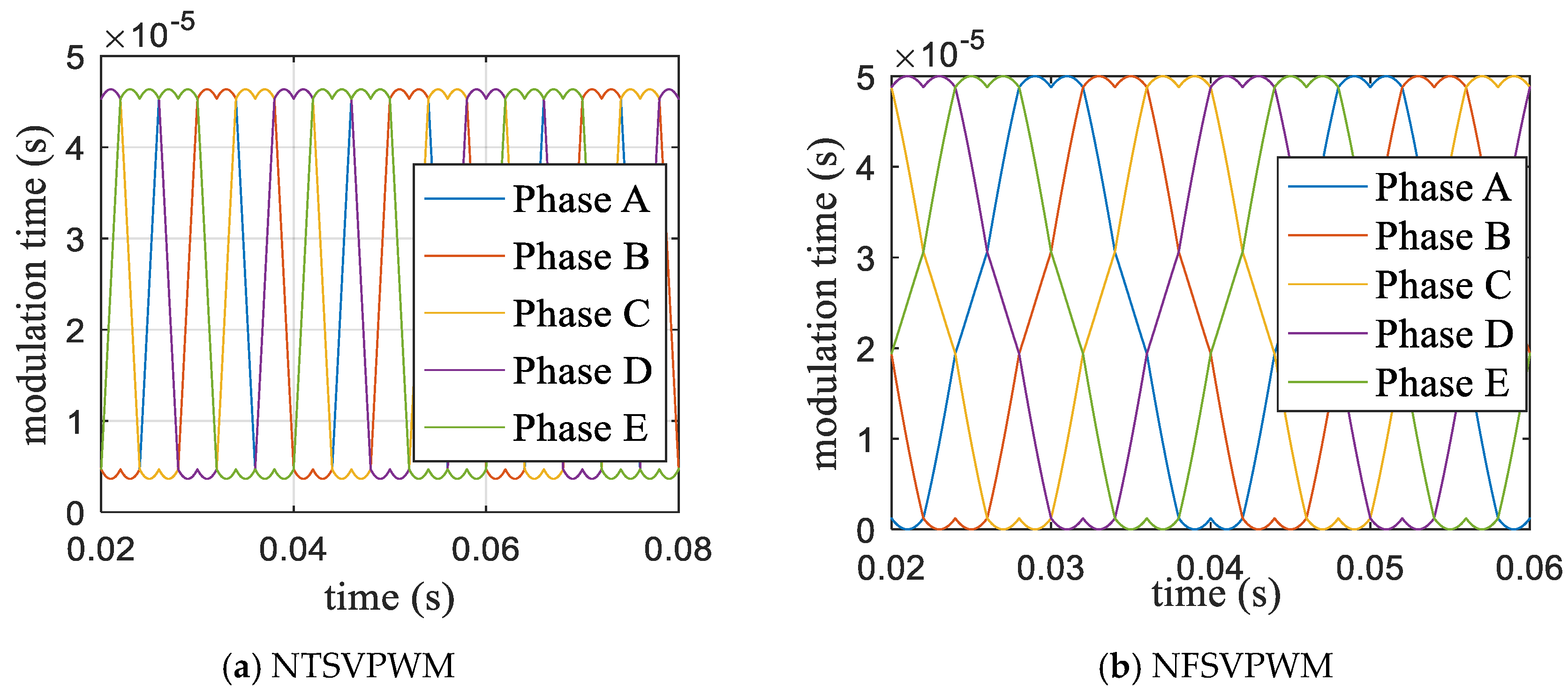
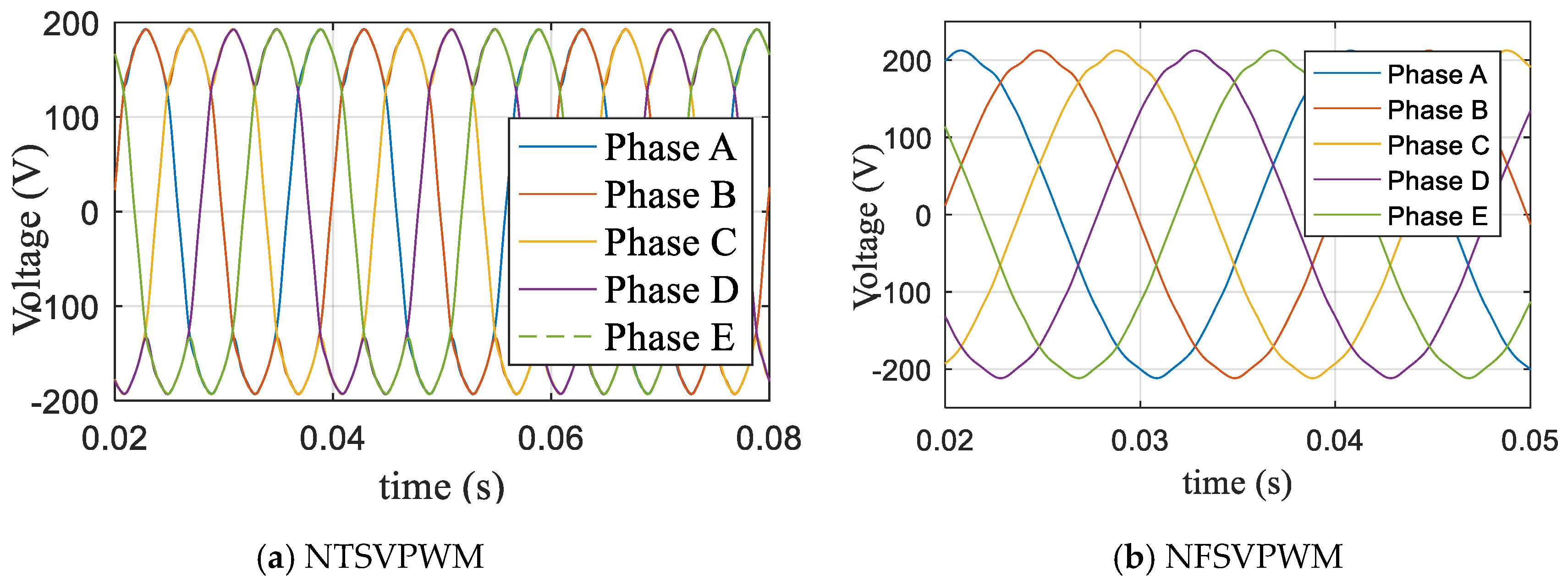
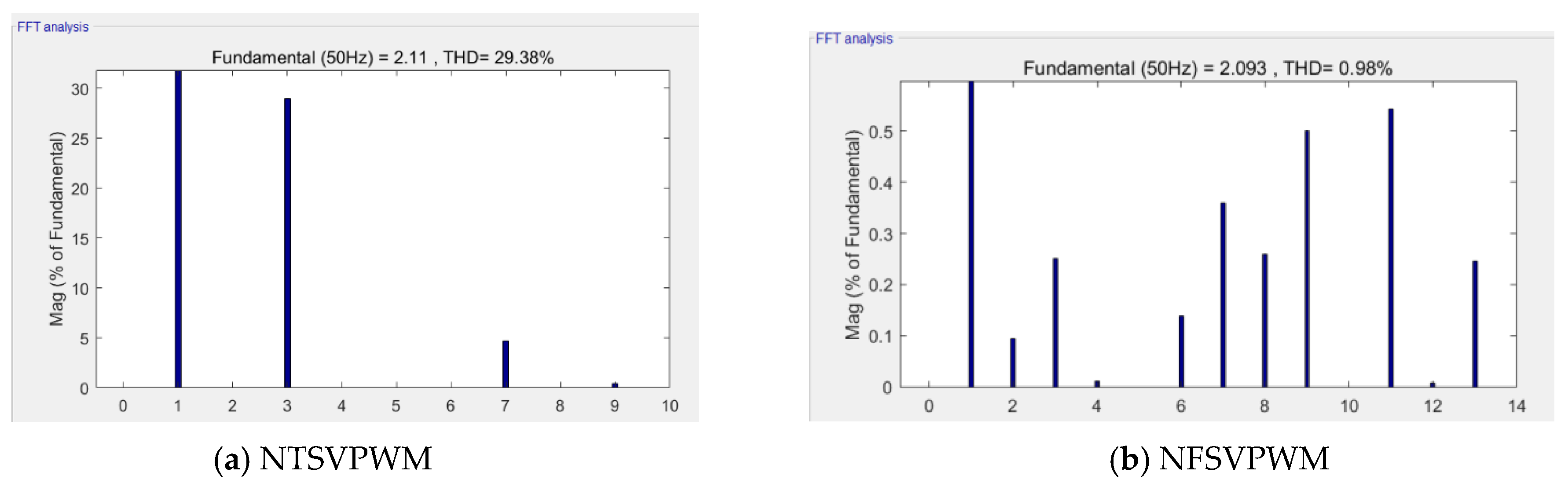
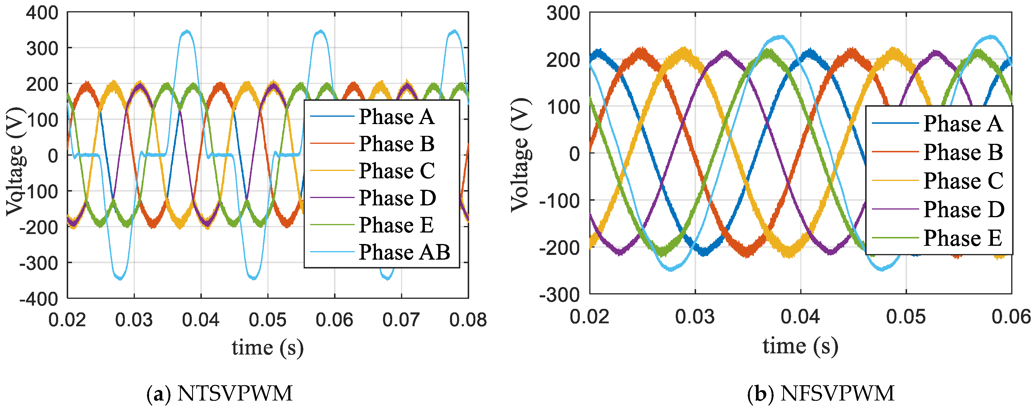
- (1)
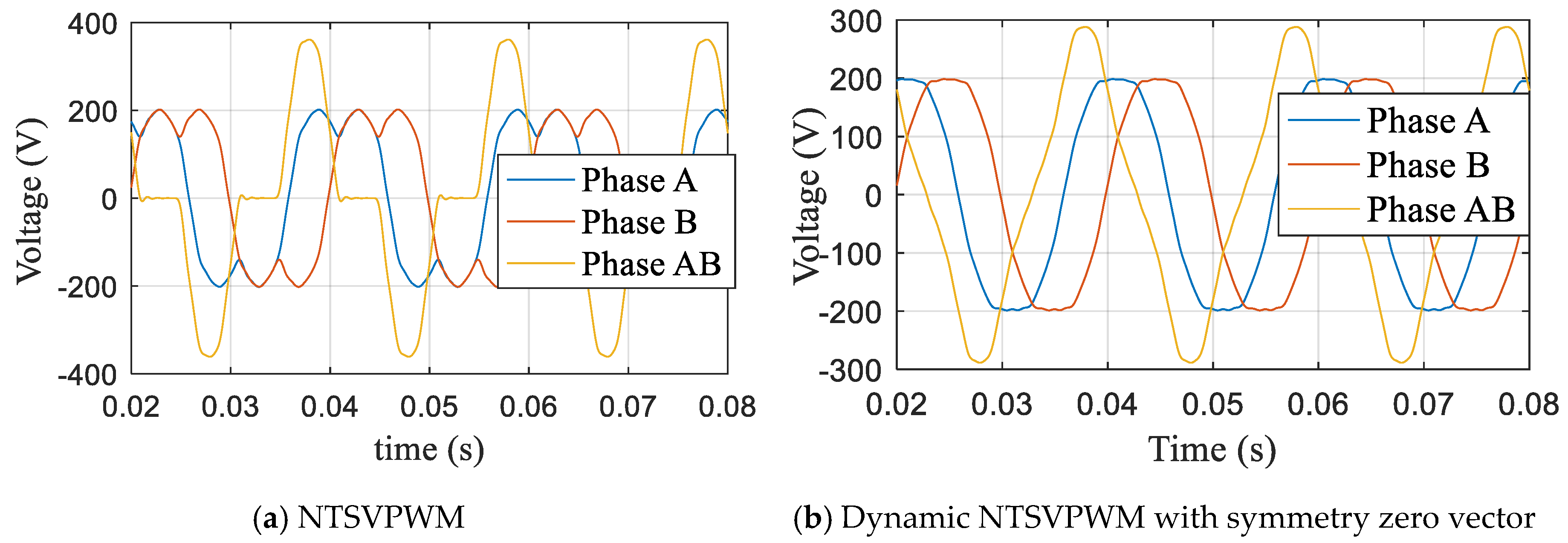
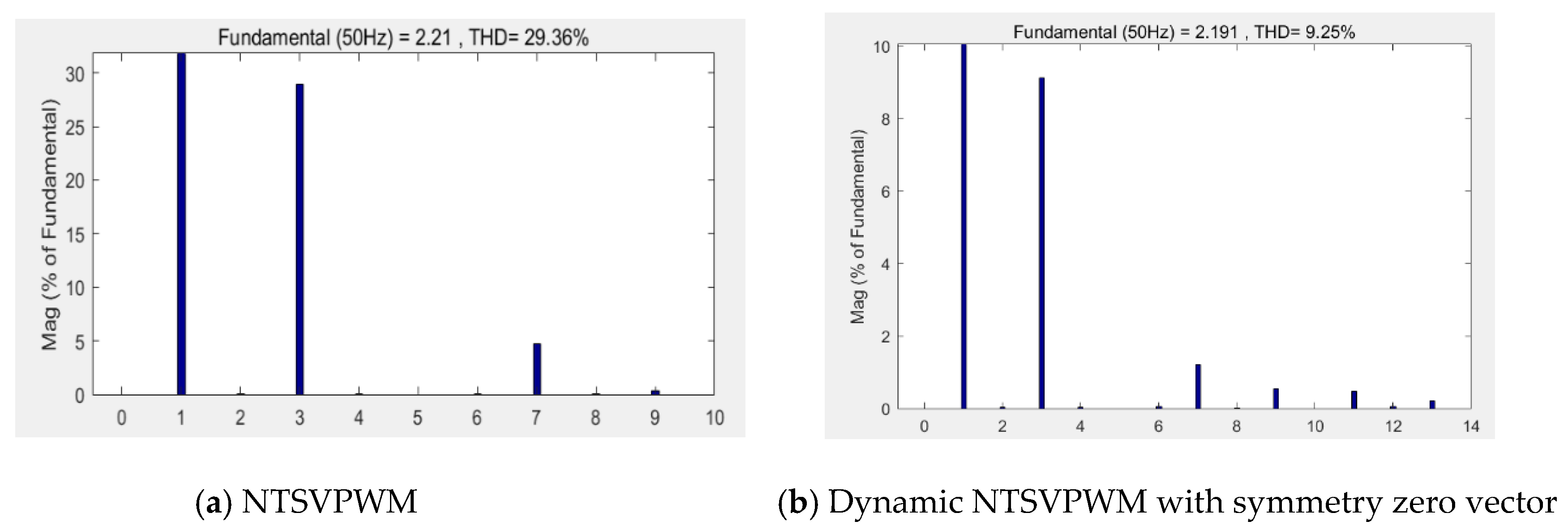
- When NTSVPWM is adopted, the lower-order harmonic is large and remains constant no matter how the modulation index ratio changes.
- (2)
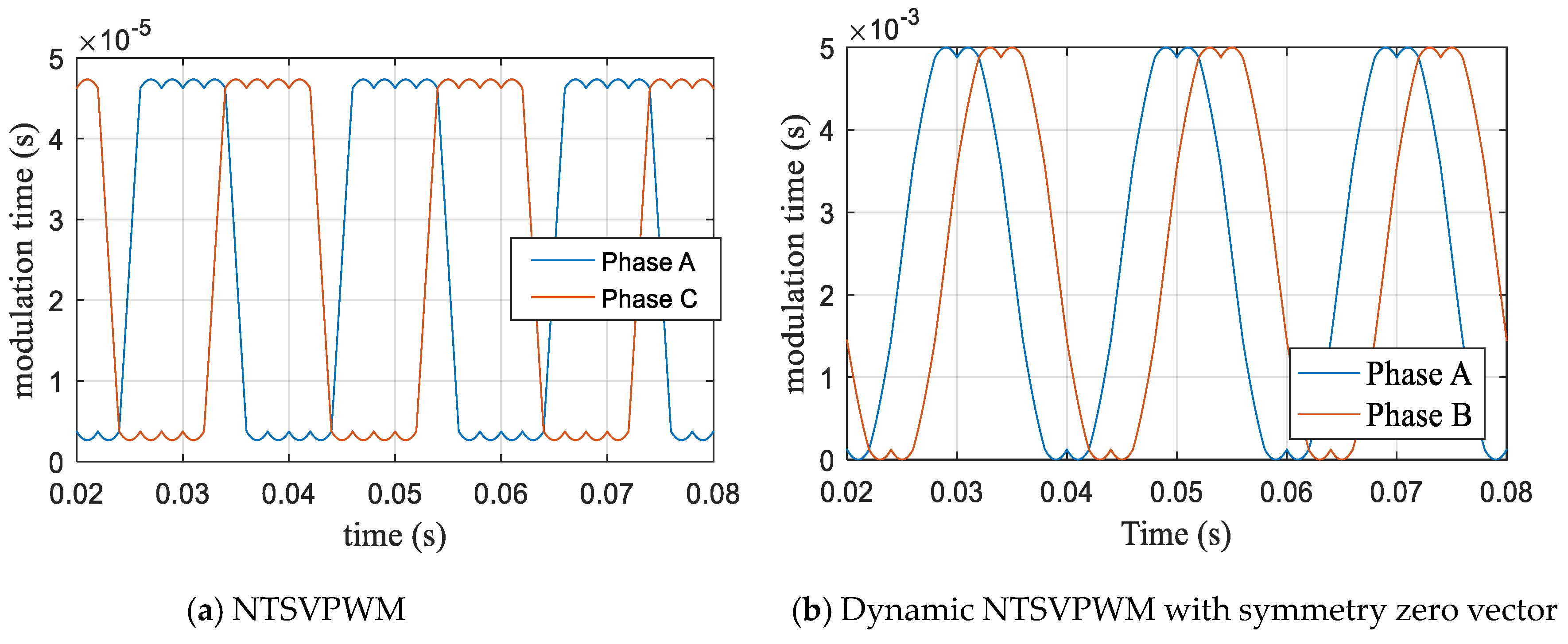
- When m ≤ 1.0514, NFSVPWM and the proposed algorithm can be used because of the small harmonic. When m > 1.0514, the dynamic NFSVPWM with a symmetry zero vector can be used to improve the DC bus utilization and harmonic.
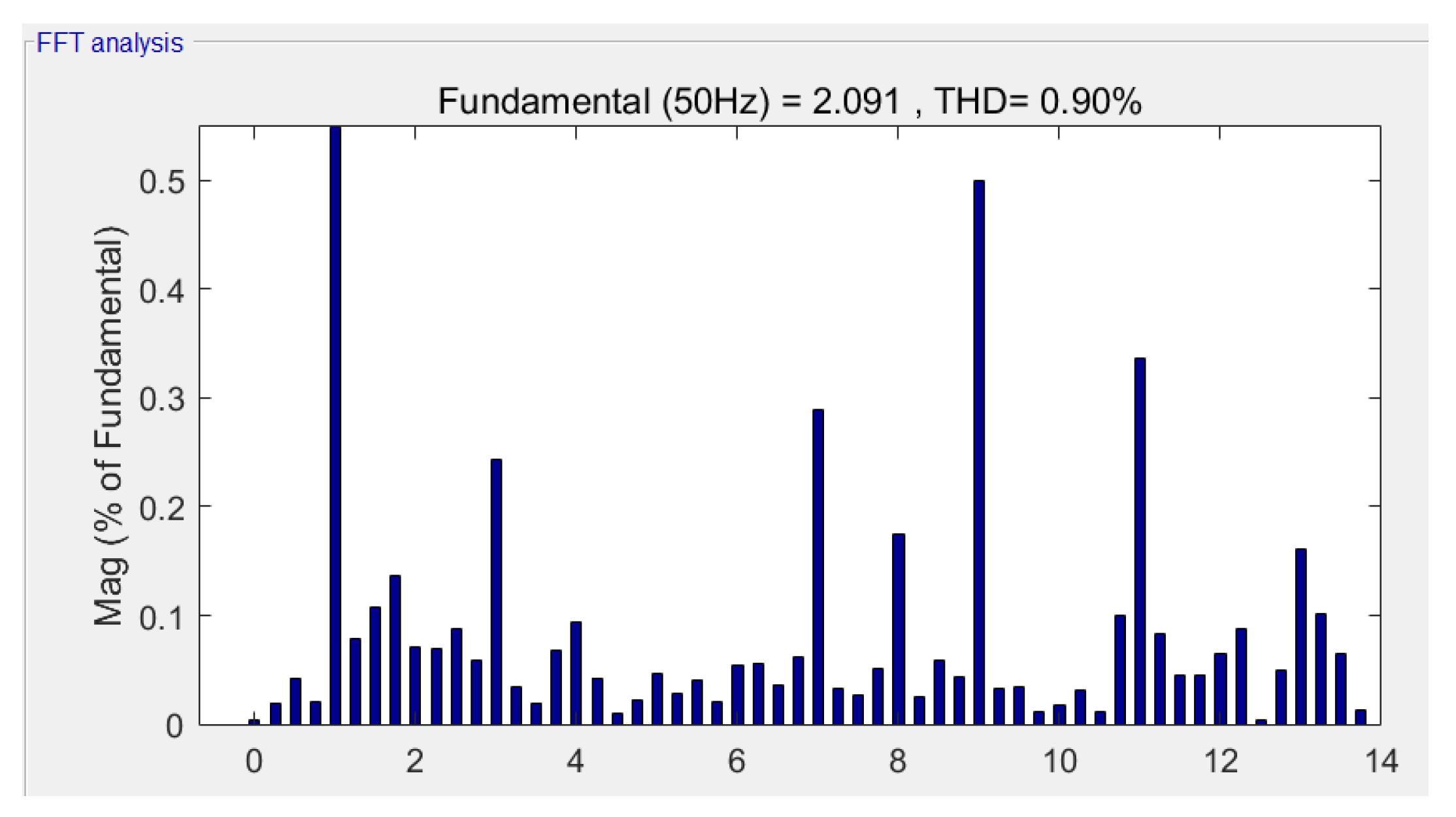
- (3)
- The proposed dynamic and adjustable new pattern four-vector SVPWM algorithm has better characteristics to improve DC-bus utilization and reduce the harmonic influence
6. Conclusions
Author Contributions
Funding
Conflicts of Interest
References
- Levi, E. Multiphase electric machines for variable-speed applications. IEEE Trans. Ind. Electron. 2008, 55, 1893–1909. [Google Scholar] [CrossRef]
- Levi, E.; Bojoi, R.; Profumo, F.; Toliyat, H.A.; Williamson, S. Multiphase induction motor drives-a technology status review. IET Electr. Power Appl. 2007, 1, 489–516. [Google Scholar] [CrossRef]
- Subotic, I.; Bodo, N.; Levi, E.; Katic, V.A.; Dumnic, B.; Milicevic, D. Overview of fast on-board integrated battery chargers for electric vehicles based on multiphase machines and power electronics. IET Electr. Power Appl. 2016, 1, 217–229. [Google Scholar] [CrossRef]
- Singh, S.; Tiwari, A.N. Simulation and Comparison of SPWM and SVPWM Control for Two Level Inverter. In Proceedings of the First International Conference on Smart Technologies in Computer and Communication, Rajasthan, India, 27–29 March 2017. [Google Scholar]
- Kumar, K.V.; Michael, P.A.; John, J.P.; Kumar, S.S. Simulation and Comparison of SPWM and SVPWM Control for Three Phase Inverter. Arpn. J. Eng. Appl. Sci. 2010, 10, 61–74. [Google Scholar]
- Lakhdari, L.; Bouchiba, B.; Bechar, M. Comparative Analysis of SVPWM and the Standard PWM Technique for Three Level Diode Clamped Inverter fed Induction Motor. Int. J. Electr. Comput. Eng. 2018, 12, 102–108. [Google Scholar]
- Show, S.K.; Parthiban, P. Analysis of current controlled voltage source Inverter with Space Vector PWM and Sinusoidal PWM techniques. In Proceedings of the International Conference on Innovations in Information, Embedded and Communication Systems, Coimbatore, India, 19–20 March 2015. [Google Scholar]
- Tang, X.; Lai, C.; Liu, Z.; Zhang, M. A svpwm to Eliminate Common-Mode Voltage for Multilevel Inverters. Energies 2017, 10, 715. [Google Scholar] [CrossRef]
- Chen, X.-Z.; Yu, Z.-P. SVPWM Modulation Algorithms in Motor Controller of Electric Vehicles. J. Tongji Univ. (Nat. Sci.) 2017, 45, 92–97. [Google Scholar]
- Gao, H.-W.; Yang, G.-J.; Liu, J. SVPWM algorithm for five-phase voltage source inverter based on modulation functions. Electr. Mach. Control. 2014, 18, 56–61. [Google Scholar]
- Yu, F.; Zhang, X.; Qiao, M. Multi-phase Carrier PWM Control Technology Based on Zero-Sequence Signal Injection. Trans. China Electrotech. Soc. 2009, 24, 127–131. [Google Scholar]
- Liu, H.; Yu, H.; Sun, L. Modulation Strategy to Reduce Common-Mode Voltage for Three-to-Five Phase Indirect Matrix Converter. In Proceedings of the International Conference on Intelligent Computing for Sustainable Energy and Environment, Shanghai, China, 12–13 September 2012; pp. 28–36. [Google Scholar]
- Pradeepa, S.; Surrendra Kumar, P.; Prakash, G. Adoption of SVPWM Technique to CSI and VSI. In Proceedings of the 2018 3rd International Conference for Convergence in Technology, Pune, India, 6–8 April 2018. [Google Scholar]
- Janaki, R.V.; Keerthipati, S. An improved SVPWM control technique to reduce winding losses of 9-phase induction motor. In Proceedings of the 2019 IEEE Region 10 Conference, Kochi, India, 17–20 October 2019. [Google Scholar]
- Biswas, J.; Nair, M.D.; Gopinath, V.; Barai, M. An optimized hybrid SVPWM strategy based on multiple division of active vector time (MDAVT). IEEE Trans. Power Electron. 2017, 32, 4607–4618. [Google Scholar] [CrossRef]
- Muthukumar, P.; Melba, P.; Jeevananthan, S. An Improved Hybrid Space Vector PWM Technique for IM Drives. Circuits Syst. 2016, 7, 2120–2131. [Google Scholar] [CrossRef][Green Version]
- Hannan, M.A.; Ali, J.A.; Mohamed, A.; Uddin, M.N. A Random Forest Regression Based Space Vector PWM Inverter Controller for the Induction Motor Drive. IEEE Trans. Ind. Electron. 2017, 64, 2689–2699. [Google Scholar] [CrossRef]
- Zhu, L.; Bu, F.; Huang, W.; Pu, T. Non-Sinusoidal Dual Random Space Vector Pulse Width Modulation Strategy for Five-Phase Inverter. Trans. China Electrotech. Soc. 2018, 33, 4824–4833. [Google Scholar]
- Karampuri, R.; Prieto, J.; Barrero, F.; Jain, S. Extension of the DTC technique to multiphase induction motor drives using any odd number of phases. In Proceedings of the 2014 IEEE Vehicle Power and Propulsion Conference (VPPC), Coimbra, Portugal, 27–30 October 2014; pp. 1–6. [Google Scholar]
- Lewicki, A.; Strankowski, P.; Morawiec, M.; Guzinski, J. Optimized Space Vector Modulation Strategy for Five Phase Voltage Source Inverter with Third Harmonic Injection. In Proceedings of the 19th European Conference on Power Electronics and Applications, Warsaw, Poland, 11–14 September 2017. [Google Scholar]
- Tang, J.; Wang, T.; Cui, S. Implementation Method of SVPWM for Five-Phase Inverters. Trans. China Electrotech. Soc. 2013, 28, 64–72. [Google Scholar]
- Ryu, H.-M.; Kim, J.-H.; Sul, S.-K. Analysis of Multiphase Space Vector Pulse-Width Modulation Based on Multiple d-q Spaces Concept. IEEE Trans. Power Electron. 2005, 20, 1364–1371. [Google Scholar] [CrossRef]
- Prieto, J.; Barrero, F.; Durán, M.J.; Marín, S.T.; Perales, M.A. SVM Procedure for n-Phase VSI with Low Harmonic Distortion in the Overmodulation Region. IEEE Trans. Ind. Electron. 2014, 61, 92–97. [Google Scholar] [CrossRef]
- Halasz, S. Overmodulation Region of Multi-phase inverters. In Proceedings of the 13th International Power Electronics and Motion Control Conference, Poznan, Poland, 1–3 September 2008. [Google Scholar]


| Space Vector | Amplitude |
|---|---|
| Large Vector, UL | |
| Middle Vector, UM | |
| Little Vector, Us | |
| Zero Vector, U0, U31 | 0 |
| Name | Parameter | Unit |
|---|---|---|
| Power | 15 | kW |
| Stator resistance | 0.35 | Ω |
| Rotor resistance | 0.331 | Ω |
| Inductance | 114.7 | mH |
| Max speed | 1450 | rpm |
| Phase voltage | 215 | V |
| Phase band angle | 36 | ° |
| Phase band number | 5 | - |
| Terminal number | 5 | - |
| Frequency | 50 | Hz |
| Pole-pair | 2 | - |
| Excitation reactance | 36.024 | Ω |
| Stator leakage reactance | 1.0727 | Ω |
| Rotor leakage reactance | 1.8726 | Ω |
| Simulation | Experiment | |||||
|---|---|---|---|---|---|---|
| Harmonic Content (%) | NTSVPWM | NFSVPWM | New | NTSVPWM | NFSVPWM | New |
| 3 | 28.9 | 0.28 | 0.21 | 28.9 | 0.26 | 0.22 |
| 7 | 4.66 | 0.35 | 0.25 | 4.67 | 0.38 | 0.26 |
| THD | 29.38 | 0.98 | 0.90 | 30.1 | 0.96 | 0.85 |
| Simulation | Experiment | |||||
|---|---|---|---|---|---|---|
| Harmonic Content (%) | NTSVPWM | NFSVPWM (Dynamic + Symmetry) | New | NTSVPWM | NFSVPWM (Dynamic + Symmetry) | New |
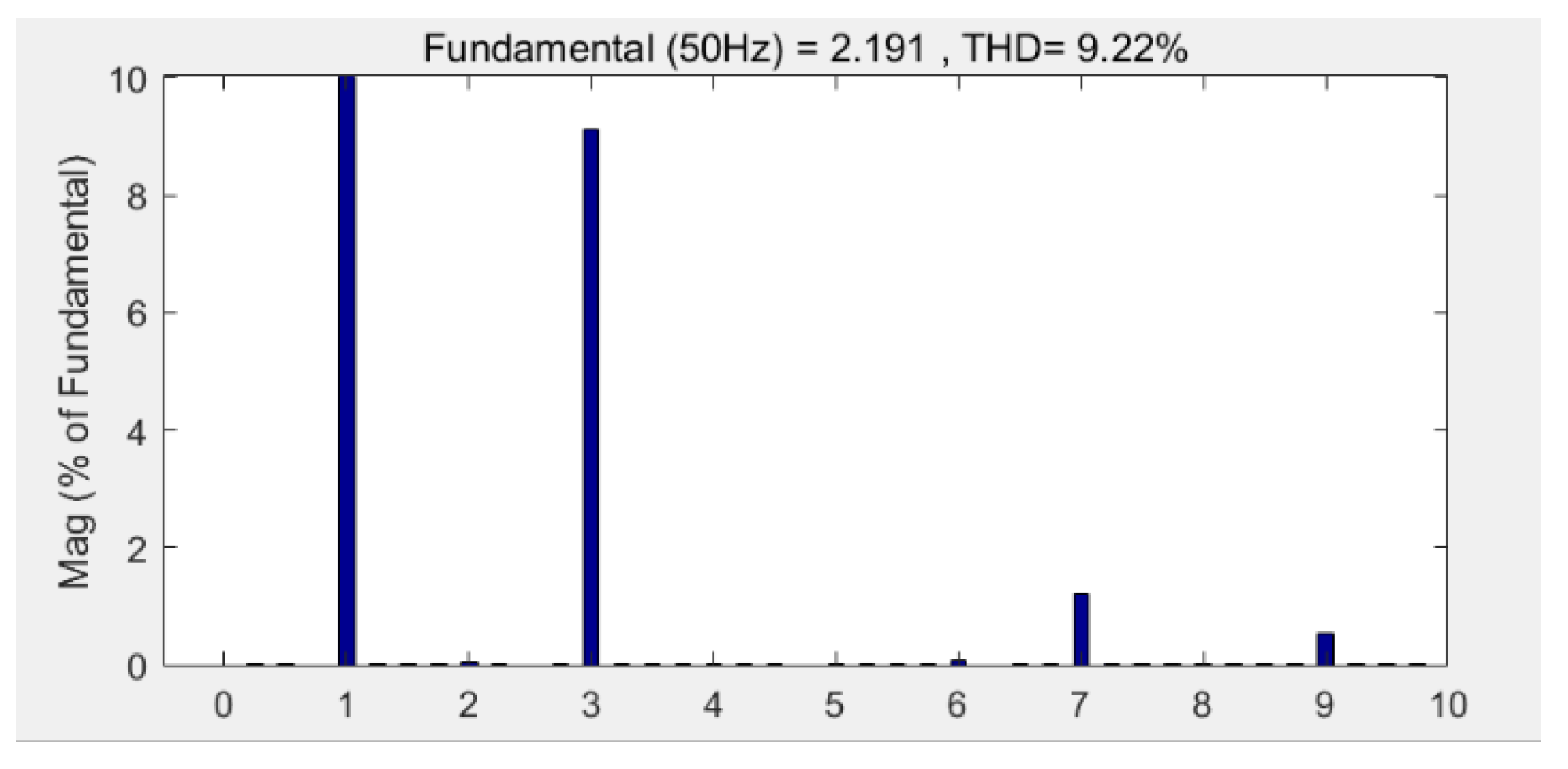
| 3 | 28.9 | 9.127 | 8.9 | 28.9 | 9.13 | 8.9 |
| 7 | 4.66 | 1.215 | 1.2 | 4.75 | 1.211 | 1.4 |
| THD | 29.36 | 9.25 | 9.22 | 29.42 | 9.46 | 9.38 |
© 2020 by the authors. Licensee MDPI, Basel, Switzerland. This article is an open access article distributed under the terms and conditions of the Creative Commons Attribution (CC BY) license (http://creativecommons.org/licenses/by/4.0/).
Share and Cite
Li, J.; Meng, D. Dynamic and Adjustable New Pattern Four-Vector SVPWM Algorithm for Application in a Five-Phase Induction Motor. Energies 2020, 13, 1856. https://doi.org/10.3390/en13071856
Li J, Meng D. Dynamic and Adjustable New Pattern Four-Vector SVPWM Algorithm for Application in a Five-Phase Induction Motor. Energies. 2020; 13(7):1856. https://doi.org/10.3390/en13071856
Chicago/Turabian StyleLi, Jinhong, and Dawei Meng. 2020. "Dynamic and Adjustable New Pattern Four-Vector SVPWM Algorithm for Application in a Five-Phase Induction Motor" Energies 13, no. 7: 1856. https://doi.org/10.3390/en13071856
APA StyleLi, J., & Meng, D. (2020). Dynamic and Adjustable New Pattern Four-Vector SVPWM Algorithm for Application in a Five-Phase Induction Motor. Energies, 13(7), 1856. https://doi.org/10.3390/en13071856