Abstract
This paper is concerned with resilient triggered control problem for load frequency control and virtual synchronous generation (LFC-VSG) scheme of discrete-time multi-area power system with parameter uncertainty, governor dead band (GDB), and low inertia under time delay and aperiodic Denial-of-Service (DoS) attacks. To reduce communication load of sleep intervals, event triggered mechanism (ETM) is introduced. A discrete-time switched delay system model is established to describe the dynamic of multi-area power system under resilient static output feedback control law. Combining piecewise Lyapunov–Krasovskii functional (LKF) method with switched system theory, a criterion is derived that the tolerant bound of attack duration and attack frequency can be estimated explicitly. Meanwhile, some sufficient conditions are obtained which can preserve weighted performance. By using linear matrix inequalities (LMIs) techniques, a co-design method is proposed to solve the control gains and trigger parameters. A simulation example of a two-area power system was carried out to verify the efficiency of our proposed resilient event based LFC-VSG scheme.
1. Introduction
With the penetration of many renewable energy resources, uncertainty and low inertia of converter based renewable energy sources (RESs) bring new challenges for frequency stabilization problem of multi-area power system [1,2]. Since the traditional load frequency control method loses its efficiency, virtual synchronous generation (VSG) concept has been proposed to imitate the behavior of synchronous generators to compensate inertia and enhance frequency stability of power system [3,4]. On the other hand, to increase the efficiency of monitoring and control, network communication techniques have been widely employed to evolve large scale power system to be networked control system. However, the increasing network attacks on power system have brought serious blackout events [5,6]. Researchers have paid much attention to the security problem of networked power system [7,8,9]. As studied, the availability and integrity of information are very essential for the system state estimation and feedback control. However, malicious cyber attacks obstructing information availability and integrity have been launched through DoS attacks and false data injection attacks [10,11]. DoS attacks interrupt communication links among system various components, leading to the missing of transmission packets in times [12], even driving system operation out of stable region. False data injection attacks inject illegal error data into communication network to pollute measurements and demands [13]. In other words, the damage on availability and integrity of information caused by network attack leads to the performance degradation of networked power system [14,15,16,17]. Thus, it is urgent to study secure control scheme to keep frequency performance resilience against DoS attacks or false data injection attacks.
1.1. Related Work
Recently, many interesting works have researched secure control problem of networked system under DoS attacks. On the one hand, for continuous-time system, a communication regulation strategy has been presented to obtain input-to-state stability (ISS) under DoS attacks modeled by average dwell time concept [18]. However, this study, based on the Lyapunov function method, cannot provide the design method of resilient control gain. By using LKF method, a resilient event-triggered mechanism and PI based control scheme were jointly designed for LFC system under DoS attacks modeled by maximum number of successive packet loss [19]. Compared with average dwell time (ADT) model [18], the attack characteristics studied in [19] have not been fully explored. For periodic DoS jamming attacks, a resilient synthesis method of event-based feedback control has been presented; a joint design method to solve parameters of event trigger and controller has been proposed by employing piecewise Lyapunov–Krasovskii functional method and switched system method [20,21]. Further, motivated by the above method, delay bound based attack detection and resilient LFC scheme have been proposed for multi-area power system under ADT model based DoS attacks [22]. On the other hand, for discrete-time stochastic system, the event-based security control problem has been studied by using stochastic analysis method to achieve mean-square security under random DoS attacks [23]. To defend against the DoS attack, a compensation mechanism cooperating with attack detection has been proposed to preserve system stochastically stable [24]. Besides, stability analysis and resilient control design under DoS attacks modeled by Markov process has been investigated using Lyapunov theory [25]. For discrete-time deterministic system, the maximum tolerable number of DoS attacks has been obtained by using Lyapunov functional method [26]. However, this paper is only concerned with the duration of DoS attack but neglects the attack frequency. It is well known that high attack frequency would also cause system instability.
1.2. Our Contributions
To the best of our knowledge, secure control design for discrete-time deterministic power system under DoS attacks has never been considered. Thus, to fill this research gap, our published work studies resilient event triggered control of uncertain discrete-time system under DoS attacks [27]. In this paper, we apply the earlier work [27] to the design of resilient LFC-VSG scheme of multi-area power system under DoS attacks. First, a discrete-time power system model is established with nonlinear dynamic governor dead band (GDB), low inertia, and parameter uncertainty under RESs disturbances. The combined control scheme consisting of load frequency control and virtual synchronous generation (LFC-VSG) is adopted and formulated as static feedback control law. Second, a DoS attack model is represented by an average dwell time (ADT) model to constrain the attack frequency and duration. Considered the mixed communication influence of DoS attacks, time delay, and event-triggered mechanism, a discrete-time switched delay system is established to describe the dynamic of power system and a weighted control problem is formulated for the frequency control of the considered power system. Piecewise Lyapunov–Krasovskii functional method and switched system method are employed to analyze the weighted performance. A criterion about the tolerable delay bound and attack frequency and duration is obtained. Then, a co-design method for event triggered mechanism and resilient control gain is presented based on linear matrix inequalities techniques. In this paper, the main contributions can be summarized as followings:
(1) Compared with our early work [27] considering resilient LFC design of discrete-time power system as a simulation example, this paper proposes a design method for resilient LFC-VSG scheme of discrete-time power system with more situations including GDB, low inertia, and uncertainty.
(2) A discrete-time switched delay system model is established to describe the frequency dynamic of multi-area power system with LFC-VSG scheme under DoS attacks.
(3) A new criterion of tolerable delay and DoS attacks in discrete-time form is derived, which is different from the one in continuous-time form.
(4) A co-design method for event-based LFC-VSG scheme is presented by employing piecewise Lyapunov–Krasovskii functional method and average dwell time approach to achieve weighted performance.
2. Problem Statement
2.1. Discrete-Time Model of Multi-Area Power System with GDB and Uncertainty under LFC-VSG Scheme
To illustrate interconnected multi-area power system with the uniform structure, Figure 1 shows the diagram of the ith area power system with RESs disturbances under LFC-VSG scheme [28] as shown in Figure 2. With Table 1, the system dynamic of the ith area power system is represented by
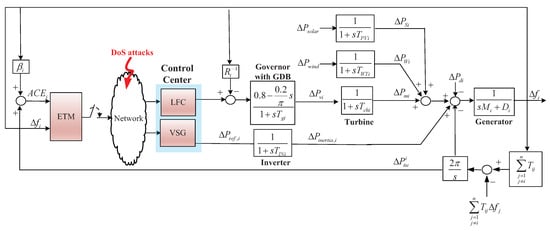
Figure 1.
The ith area power system with event-triggered mechanism based LFC-VSG scheme.
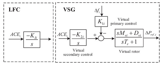
Figure 2.
LFC-VSG scheme of the ith area power system.

Table 1.
Definition of the ith area power system parameters.
Governor dead band (GDB) [29]: The governor dead-band nonlinearity leads to sustained sinusoidal oscillation of natural period of about , namely . By Fourier transformation with neglecting higher order term, the transfer function of governor with nonlinearity is represented by
Speed Droop Coefficient Uncertainty [30]: The parameter uncertainty of power system referring to the speed droop coefficient is considered here. The uncertainty of speed droop coefficient is represented by , where .
Then, the ith area power system can be formed by a continuous-time system model
where
Combining load frequency control (LFC) scheme and virtual synchronous generation (VSG) scheme (Figure 2), a static output feedback control law is adopted for the ith area power system
where .
The ith area power system can be represented by a discrete-time system model
where , , , , .
Based on the ith area power system model in Equation (4), a linear discrete-time model is established for a n-area power system with parameter uncertainty.
where
The argument form of control law can be rewritten as
where
2.2. Discrete-Time Power System under DoS Attacks and Event-Triggered Mechanism
DoS attacks launch in feedback channel to prevent measurements arriving at control center. Here, a class of aperiodic DoS attacks is considered. Define sleep intervals and attack intervals . Then, DoS attacks can be represented by a switched signal.
where the on/off instant represents the th ending time of DoS attacks with , while the off/on instant represents the nth beginning time of DoS attacks.
Denote the sum number of off/on instants as attack frequency during and attack duration during . Then, the upper bound of attack frequency and duration is constrained by
where and .
During sleep intervals , the feedback channel recovers normal communication. Besides of network induced delay, the processing of the composite feedback signal consisting of , , , and would increase the computation load and waste much time to influence the real time control. To reduce the computation and communication load, event triggered mechanism is embedded in PMU nodes, which decides whether to send the measurements .
where with , and . Note that, for discrete-time system, the minimum triggered interval is sample periodic h so that it avoids Zeno behavior.
Introduce the transmission delay for the triggered signal , where . Further, the sleep interval can be divided by
where the triggered interval is specified by
with and .
Further, the triggered interval can be divided by
Case I: if , . let which satisfies . Case II: if , there exists satisfying . Hence, the inner interval is specified by
Then, introduce a virtual delay
which satisfies .
Further, we introduce trigger error
Thus, the resilient triggering control inputs are generated by
On the basis of above analysis, a discrete-time switched delay system is established as
and, according to Equation (9), by denoting , the trigger condition is rewritten as
For the established power system in Equation (11), the research objective of this study is to analyze the resilience performance and provide the design method for the resilient static feedback control in Equation (10) to preserve weighted performance:
(1) The power system in Equation (11) is exponentially stable when .
(2) With zero initial condition, the power system in Equation (11) has weighted -gain such that
where the scalars , and .
3. Analysis of Weighted Performance
In this section, the weighted performance of the power system in Equation (11) is analyzed by combining delay system method and switched system method.
Theorem 1.
Given positive scalars , , γ, σ, the switched time delay system in Equation (11) is exponentially stable with weighted -gain under DoS attacks (), if there exist positive definite matrices , Ω and appropriate dimension matrices satisfying
where
Proof.
Please see Appendix A.1 in the Appendix A. □
Remark 1.
The resulting criterion in Equation (14) is the main contribution of this paper. The comprehensive influence of DoS attacks and time delay is bounded by the indices , , and . The satisfaction of this criterion can guarantee the frequency stability of the considered multi-area power system. Considering the positive term , and the negative term , it requires a small and large and . It is reasonable that the frequency stability of power system can be preserved with small delay margin, low attack frequency , and small attack duration ratio .
4. Design of Resilient Triggering Control
According to the resulting sufficient conditions in Theorem 1, this section provides a design method of resilient event-based LFC-VSG scheme on the basis of linear matrix inequalities techniques (LMIs).
Lemma 1
([31]).For real matrices and , it holds that
for any satisfying , if and only if there exists a positive scalar , such that
Theorem 2.
Given positive scalars ε, , δ, γ, ζ, , and , , the switched time delay system in Equation (11) is exponentially stable with weighted -gain , if Equation (14) holds and there exist positive definite matrices , Ω and appropriate dimension matrices satisfying
where
Then, both the control gain and the trigger parameter can be obtained from the solutions of the above LMIs.
Proof.
Please see Appendix A.2 in the Appendix A. □
Remark 2.
Theorem 2 relies nonlinearly on the parameters ε, , γ, ζ, σ, and δ. Once these parameters are given, the matrix inequalities in Equations (20)–(25) would become LMIs, by solving which LFC-VSG gain K and trigger parameter Ω can be further obtained by using MATLAB Toolbox YALMIP with solver MOSEK. Furthermore, the proposed design method allows for a trade-off: performance index versus delay margin and DoS attacks .
5. Simulation
To study the performance of the proposed event-based LFC-VSG scheme, a two-area power system with physical constraints (uncertainty, low inertia and GDB) and cyber disturbance (time delay and DoS attacks) was simulated using MATLAB. The nominal available parameters of the considered two-area power system were borrowed from [4,28], as listed in Table 2. The thermal power plants with various capacities in each area are equivalent to a single synchronous generator. The time constants of the disturbances terms of solar plant and farm plant for two-area power system are simply assumed to be same due to the used uniform inverters in engineering. From another aspect, the disturbance of RESs is not the key factor affecting the stability of power system in this study. The parameters of virtual synchronous generations selected by PSO algorithm [28] are larger than the inertia and damping coefficients of the equivalent SG to enhance system inertia.
Table 2.
The parameters of two-area power system.
Set and . The inertia of power system reduces . According to Theorem 2, the control gain K and the trigger parameters were obtained using MATLAB Toolbox YALMIP with solver MOSEK.
With the solved triggered control parameters, the frequency derivation and the tie-line power exchange of the two-area power system in Equation (5) are depicted in Figure 3 and Figure 4, where the time intervals with grey background represent DoS attacks. Multi-disturbances such as load change, wind farm disturbance and solar farm disturbance are depicted in Figure 5 and Figure 6. It can be observed that the trajectories of frequency derivation and tie-line power exchange approach to zeros after oscillation. By calculation, the decay rate is , which verifies the achievement of exponential stability under our method. The oscillation in the time interval is more serious than that in the time interval even though the former disturbances is less than the latter because DoS attacks frequently occur in the beginning time interval to prevent the implementation of LFC-VSG control signals while the sleep interval guarantees power system restoring much resilient performance against DoS attack in the time interval . Thus, it is necessary to constrain attack frequency, which verifies the reasonableness of our research motivation. On the other hand, the theory value of performance level is . By calculation, the actual performance level is , which is less than . Thus, the power system is exponentially stable with the desired performance level, which verifies the efficiency of our design method.
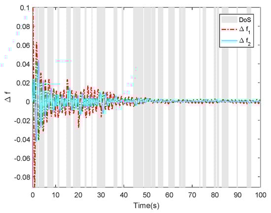
Figure 3.
Frequency derivations of two area power system.
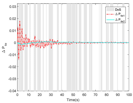
Figure 4.
Tie-line power exchanges of two area power system.
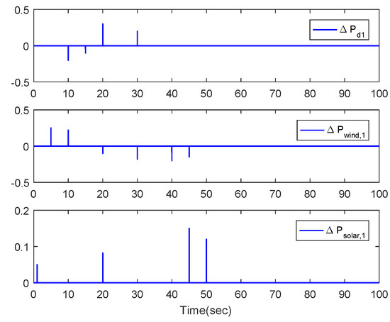
Figure 5.
Multi-disturbances in first area power system.
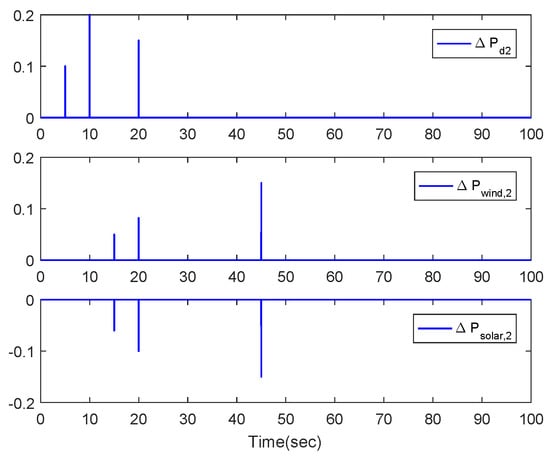
Figure 6.
Multi-disturbances in the second area power system.
The triggered instants and triggered intervals are depicted in Figure 7. The event-triggered mechanism is operated during sleep intervals while it stops working to save much energy during attack intervals. It can be observed that the average of release time intervals during is larger than that during because the power system with the worse system performance requires many real-time control updates while power system operation in steady state needs low frequency of control update. Thus, the designed ETM can provide an automatic regulation of communication according to the operation state of power system. Compared with the sample time , the transmission rate during sleep intervals was calculated as , which is efficient to reduce the communication load while preserving system performance.
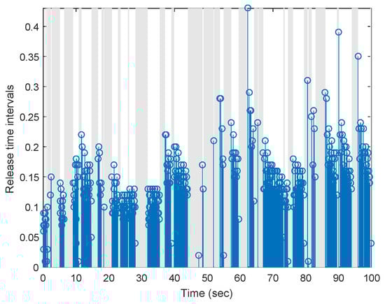
Figure 7.
Release instants and release intervals of ETM.
In the next simulation, the influence of communication factors including delay and DoS attacks on power system resilient performance was studied. According to the resilient condition in Equation (14) in Theorem 1, the quantified results show the relationships among exponential decay rate , weight level , DoS attacks parameters and , and delay bound . Note that represents the total duty cycle of attack duration while represents attack frequency. For fixed , other parameters being same as before, the performance indices and are decreased with the increasing of , as shown in Table 3. It indicates that the performance of power system would be seriously deteriorated with the large attack duration . In Table 4, for fixed , the performance level and are increased with the decrease of . It indicates that the high attack frequency would brings damage on the frequency performance of power system. The resulting conclusions are reasonable to meet common sense. On the other hand, although both attack frequency and duration could lead to the performance deterioration of power system, the influence of attack duration is more serious than attack frequency.
Table 3.
and for various with given .
Table 4.
and for various with given .
Transmission delay and DoS attacks would bring comprehensive influence on frequency stability of power system. Hence, it is interesting to study the relationship of delay bound and DoS attacks duration. For a given average dwell time , the attack duration ratio is decreased with the increase of in Table 5. It indicates that the influence of delay and DoS attacks are additive because, when there is a large communication delay, the power system would only tolerate weak DoS attacks to preserve the desired performance.
Table 5.
for various with given .
Remark 3.
Indeed, the numerical evaluation can verify the usefulness of our proposed theory in a limited level. The practicality should be verified by using real time laboratory experiment, such as Analog Power System Simulation (APSS) implemented by operational amplifiers and electronic circuits, which is closer to the real-world power system. However, our study platform at present lacks this kind of experiment environment. Hence, we only performed numerical simulation experiment to verify the validity of our method using MATLAB ToolBox. In the study of LFC system, many researchers also use numerical simulation to verify their theories. In our future work, we will build a physical power system platform or real time semi-physical simulation platform to support our theory study.
6. Conclusions
The resilient control problem of event-based load frequency control and virtual synchronous generation (LFC-VSG) scheme of discrete-time multi-area power system with uncertainty, low inertia, and GDB under time delay and DoS attacks is studied. Considering the average dwell time (ADT) model-based DoS attacks influencing on the remote communication network of LFC-VSG scheme, a discrete-time switched delay system is established to describe multi-area power system dynamic. Even-triggered mechanism (ETM) is introduced to reduce the communication load of LFC-VSG control loop. By using piecewise Lyapunov–Krasovskii functional method and switched system method, a criterion quantifying the tolerant DoS attack (ADT and duty cycle) and delay bound is proposed. Meanwhile, some sufficient conditions are derived to preserve weighted performance. Accordingly, a co-design method for ETM and LFC-VSG scheme is given in terms of LMIs. Aa simulation of two-area power system with the designed resilient event-based LFC-VSG scheme was carried out to illustrate the validity of our theory. In the future, renewable energy resources participating in remote frequency regulation will be considered and another network attack, namely false data injection attack, will be studied. The proposed method combining piecewise LFK and switched system method provides a flexible way for the system synthesis when countering complex cyber-physical factors. For improvement, advanced Lyapunov functional and integral inequality technique can be employed to reduce the conservatism of this conclusion.
Author Contributions
Z.C. designed the control strategy and wrote the manuscript; S.H. checked the whole manuscript; J.M. provided study resources of power system. All authors have read and agreed to the published version of the manuscript.
Funding
This work was supported in part by the National Natural Science Foundation of China under Grant (No. 61673223, No. 61533010, No. 61633016); the Six Talent Peaks Project of Jiang-su Province of China (Grant No. RLD201810); the QingLan Project of Jiangsu Province of China (Grant No. QL 04317006); Postgraduate Research & Practice Innovation Program of Jiangsu Province under Grant (No. KYCX19_0904, KYCX19_0923).
Conflicts of Interest
The authors declare no conflict of interest.
Appendix A
Appendix A.1. Proof of Theorem 1
Construct a piecewise Lyapunov–Krasovskii functional (LKF) ()
where , and .
Case 1.
Case 2.
Further, one has
Stability analysis:
According to Equation (19), one has
With , by recursing Equations (A3) and (A4), it can be obtained that
where and . According to Equation (14), it can be guaranteed that . Thus, the switched system in Equation (11) is exponentially stable.
performance analysis:
For the convenience of performance analysis, note that
For , the following inequality is satisfied
Let . Adding both sides of the above inequality from to , it can be derived that
Further, it has
For simplification, denote . Multiplying both sides of the above inequality with , it develops that
Denote . According to Equation (14), one has , which indicates . Further, one has
Appendix A.2. Proof of Theorem 2
First, the uncertainty matrices can be decomposed by , where
Further, the argument uncertainty matrix is constructed by where and is an unknown matrix, which is Lebesque measurable and satisfies .
According to the construction on the uncertainties , replacing A by , Equations (15) and (17) can be rewritten by
where
Denote that
Based on Lemma 1, Equation (A8) can be converted to
by using Schur complement lemma, which is expanded to
where , and
Further, define that , , , , , , , and . Based on the inequality technique and , using Schur complementary Lemma l, pro-and pre-multiplying Equation (A10) with respectively, and pro- and pre-multiplying Equation (A11) with respectively, Equations (20) and (21) can be obtained. Accordingly, Equations (16), (18), and (19) can be converted to the LMIs in Equations (22)–(24). Equation (25) is introduced to deal with nonlinear term .
References
- Bevrani, H.; Ghosh, A.; Ledwich, G. Renewable energy sources and frequency regulation: Survey and new perspectives. IET Renew. Power Gener. 2010, 4, 438–457. [Google Scholar] [CrossRef]
- Dreidy, M.; Mokhlis, H.; Mekhilef, S. Inertia response and frequency control techniques for renewable energy sources: A review. Renew. Sustain. Energy Rev. 2017, 69, 144–155. [Google Scholar] [CrossRef]
- Bevrani, H.; Ise, T.; Miura, Y. Virtual synchronous generators: A survey and new perspectives. Int. J. Electr. Power Energy Syst. 2014, 54, 244–254. [Google Scholar] [CrossRef]
- Kerdphol, T.; Rahman, F.S.; Mitani, Y. Virtual inertia control application to enhance frequency stability of interconnected power systems with high renewable energy penetration. Energies 2018, 11, 981. [Google Scholar] [CrossRef]
- Liang, G.; Weller, S.R.; Zhao, J.; Luo, F.; Dong, Z.Y. The 2015 ukraine blackout: Implications for false data injection attacks. IEEE Trans. Power Syst. 2016, 32, 3317–3318. [Google Scholar] [CrossRef]
- Sgouras, K.I.; Birda, A.D.; Labridis, D.P. Cyber attack impact on critical smart grid infrastructures. In Proceedings of the ISGT 2014, Washington, DC, USA, 19–22 February 2014; pp. 1–5. [Google Scholar]
- Wang, W.; Lu, Z. Cyber security in the smart grid: Survey and challenges. Comput. Netw. 2013, 57, 1344–1371. [Google Scholar] [CrossRef]
- Teixeira, A.; Shames, I.; Sandberg, H.; Johansson, K.H. A secure control framework for resource-limited adversaries. Automatica 2015, 51, 135–148. [Google Scholar] [CrossRef]
- Ding, D.; Han, Q.L.; Xiang, Y.; Ge, X.; Zhang, X.M. A survey on security control and attack detection for industrial cyber-physical systems. Neurocomputing 2018, 275, 1674–1683. [Google Scholar] [CrossRef]
- Guan, Y.; Ge, X. Distributed attack detection and secure estimation of networked cyber-physical systems against false data injection attacks and jamming attacks. IEEE Trans. Signal Inf. Process. Over Netw. 2018, 4, 48–59. [Google Scholar] [CrossRef]
- Liu, J.; Tian, E.; Xie, X.; Lin, H. Distributed event-triggered control for networked control systems with stochastic cyber-attacks. J. Frankl. Inst. 2019, 356, 10260–10276. [Google Scholar] [CrossRef]
- Amin, S.; Cárdenas, A.A.; Sastry, S.S. Safe and secure networked control systems under denial-of-service attacks. In Proceedings of the International Workshop on Hybrid Systems: Computation and Control, San Francisco, CA, USA, 13–15 April 2009; Springer: Berlin/Heidelberg, Germany, 2009; pp. 31–45. [Google Scholar]
- Pang, Z.H.; Liu, G.P.; Zhou, D.; Hou, F.; Sun, D. Two-channel false data injection attacks against output tracking control of networked systems. IEEE Trans. Ind. Electron. 2016, 63, 3242–3251. [Google Scholar] [CrossRef]
- Liu, S.; Liu, X.P.; El Saddik, A. Denial-of-service (DoS) attacks on load frequency control in smart grids. In Proceedings of the 2013 IEEE PES Innovative Smart Grid Technologies Conference (ISGT), Washington, DC, USA, 24–27 February 2013; pp. 1–6. [Google Scholar]
- Manandhar, K.; Cao, X.; Hu, F.; Liu, Y. Detection of faults and attacks including false data injection attack in smart grid using Kalman filter. IEEE Trans. Control. Netw. Syst. 2014, 1, 370–379. [Google Scholar] [CrossRef]
- Zhang, H.; Qi, Y.; Wu, J.; Fu, L.; He, L. DoS attack energy management against remote state estimation. IEEE Trans. Control. Netw. Syst. 2018, 5, 383–394. [Google Scholar] [CrossRef]
- Xiao, S.; Han, Q.L.; Ge, X.; Zhang, Y. Secure Distributed Finite-Time Filtering for Positive Systems Over Sensor Networks Under Deception Attacks. IEEE Trans. Cybern. 2019. [Google Scholar] [CrossRef] [PubMed]
- De Persis, C.; Tesi, P. Input-to-state stabilizing control under denial-of-service. IEEE Trans. Autom. Control 2015, 60, 2930–2944. [Google Scholar] [CrossRef]
- Peng, C.; Li, J.; Fei, M. Resilient Event-Triggering H∞ Load Frequency Control for Multi-Area Power Systems With Energy-Limited DoS Attacks. IEEE Trans. Power Syst. 2017, 32, 4110–4118. [Google Scholar] [CrossRef]
- Hu, S.; Yue, D.; Xie, X.; Chen, X.; Yin, X. Resilient event-triggered controller synthesis of networked control systems under periodic DoS jamming attacks. IEEE Trans. Cybern. 2018, 49, 4271–4281. [Google Scholar] [CrossRef]
- Chen, X.; Wang, Y.; Hu, S. Event-based robust stabilization of uncertain networked control systems under quantization and denial-of-service attacks. Inf. Sci. 2018, 459, 369–386. [Google Scholar] [CrossRef]
- Cheng, Z.; Yue, D.; Hu, S.; Xie, X.; Huang, C. Detection-based weighted H∞ LFC for multi-area power systems under DoS attacks. IET Control Theory Appl. 2019, 13, 1909–1919. [Google Scholar] [CrossRef]
- Ding, D.; Wang, Z.; Wei, G.; Alsaadi, F.E. Event-based security control for discrete-time stochastic systems. IET Control. Theory Appl. 2016, 10, 1808–1815. [Google Scholar] [CrossRef]
- Su, L.; Ye, D. A cooperative detection and compensation mechanism against Denial-of-Service attack for cyber-physical systems. Inf. Sci. 2018, 444, 122–134. [Google Scholar] [CrossRef]
- Sun, H.; Peng, C.; Yang, T.; Zhang, H.; He, W. Resilient control of networked control systems with stochastic denial of service attacks. Neurocomputing 2017, 270, 170–177. [Google Scholar] [CrossRef]
- Zhang, J.; Peng, C.; Masroor, S.; Sun, H.; Chai, L. Stability analysis of networked control systems with denial-of-service attacks. In Proceedings of the 2016 UKACC 11th International Conference on Control (CONTROL), Belfast, UK, 31 August–2 September 2016; pp. 1–6. [Google Scholar]
- Cheng, Z.; Yue, D.; Hu, S.; Chen, L. Resilient H∞ triggering control for uncertain discrete-time system against DoS attacks. In Proceedings of the IECON 2019-45th Annual Conference of the IEEE Industrial Electronics Society, Lisbon, Portugal, 14–17 October 2019; Volume 1, pp. 6285–6290. [Google Scholar]
- Magdy, G.; Shabib, G.; Elbaset, A.A.; Mitani, Y. Renewable power systems dynamic security using a new coordination of frequency control strategy based on virtual synchronous generator and digital frequency protection. Int. J. Electr. Power Energy Syst. 2019, 109, 351–368. [Google Scholar] [CrossRef]
- Gozde, H.; Taplamacioglu, M.C. Automatic generation control application with craziness based particle swarm optimization in a thermal power system. Int. J. Electr. Power Energy Syst. 2011, 33, 8–16. [Google Scholar] [CrossRef]
- Liu, S.; Luo, W.; Wu, L. Co-Design of Distributed Model-Based Control and Event-Triggering Scheme for Load Frequency Regulation in Smart Grids. IEEE Trans. Syst. Man, Cybern. Syst. 2018. [Google Scholar] [CrossRef]
- Wang, Y.; Xie, L.; De Souza, C.E. Robust control of a class of uncertain nonlinear systems. Syst. Control. Lett. 1992, 19, 139–149. [Google Scholar] [CrossRef]


© 2020 by the authors. Licensee MDPI, Basel, Switzerland. This article is an open access article distributed under the terms and conditions of the Creative Commons Attribution (CC BY) license (http://creativecommons.org/licenses/by/4.0/).