Electromagnetic–Mechanical Coupling Optimization of an IPM Synchronous Machine with Multi Flux Barriers


Abstract
1. Introduction
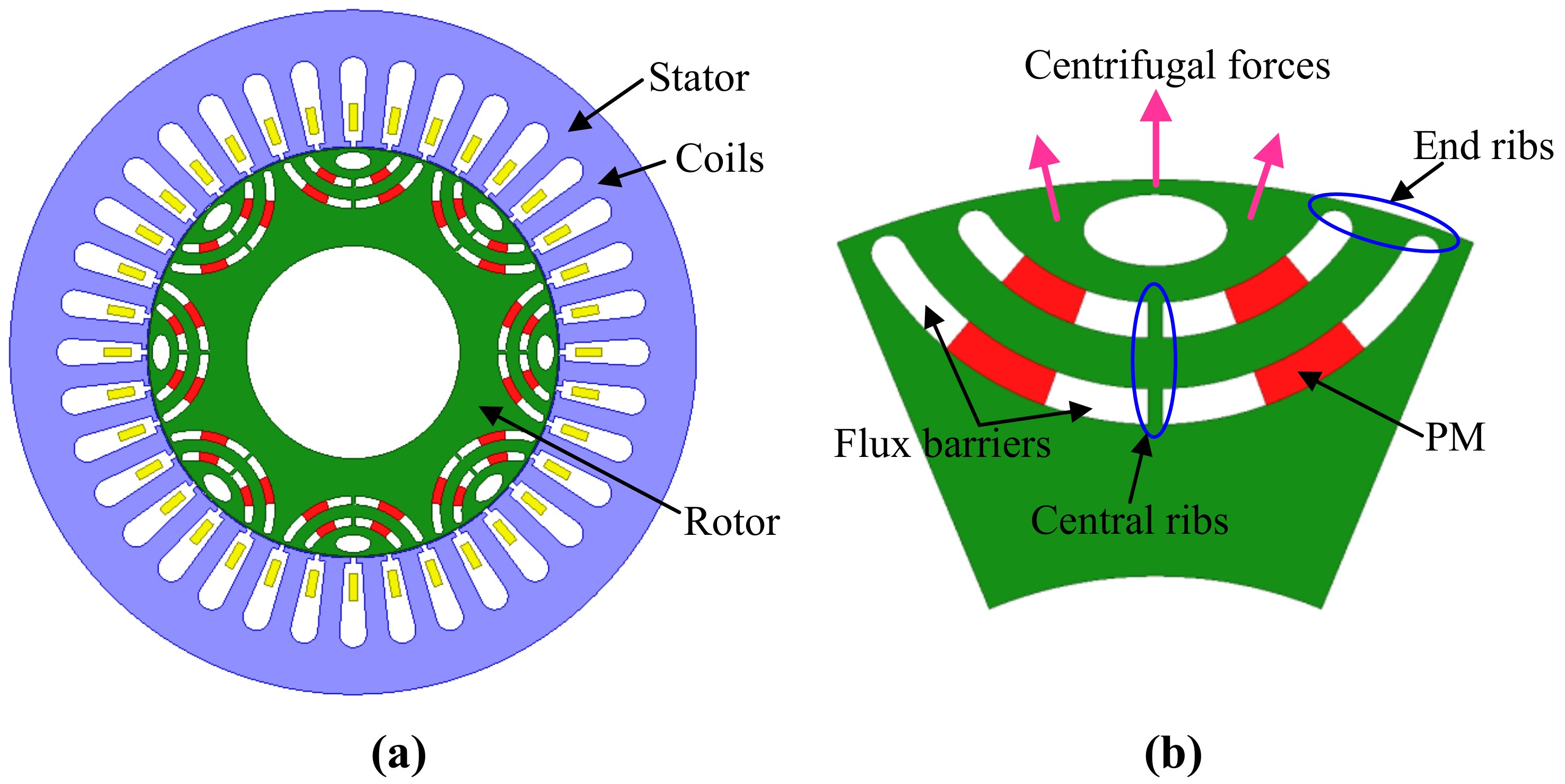
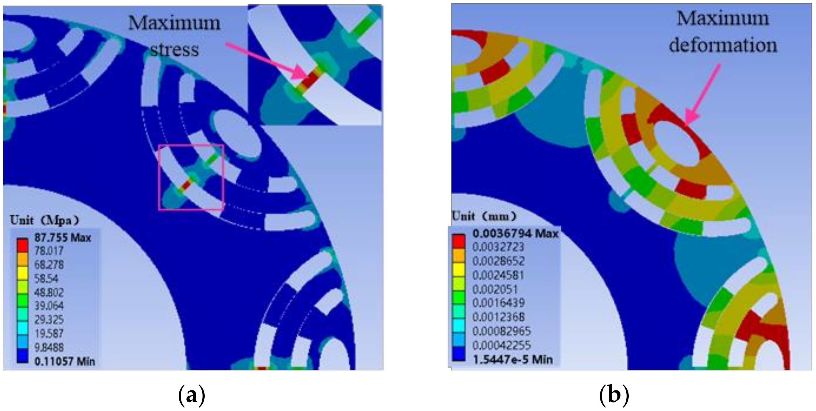
2. Machine Structure and Stress Analysis
3. Electromagnetic–Mechanical Coupling Optimization
3.1. Optimization Strategy
3.2. Objectives, Objective Functions, and Constraints
3.2.1. Maximum Stress Coupling Optimization Zone
3.2.2. Maximum Deformation Coupling Optimization Zone
3.3. Boundary Conditions, Loads, and Solution
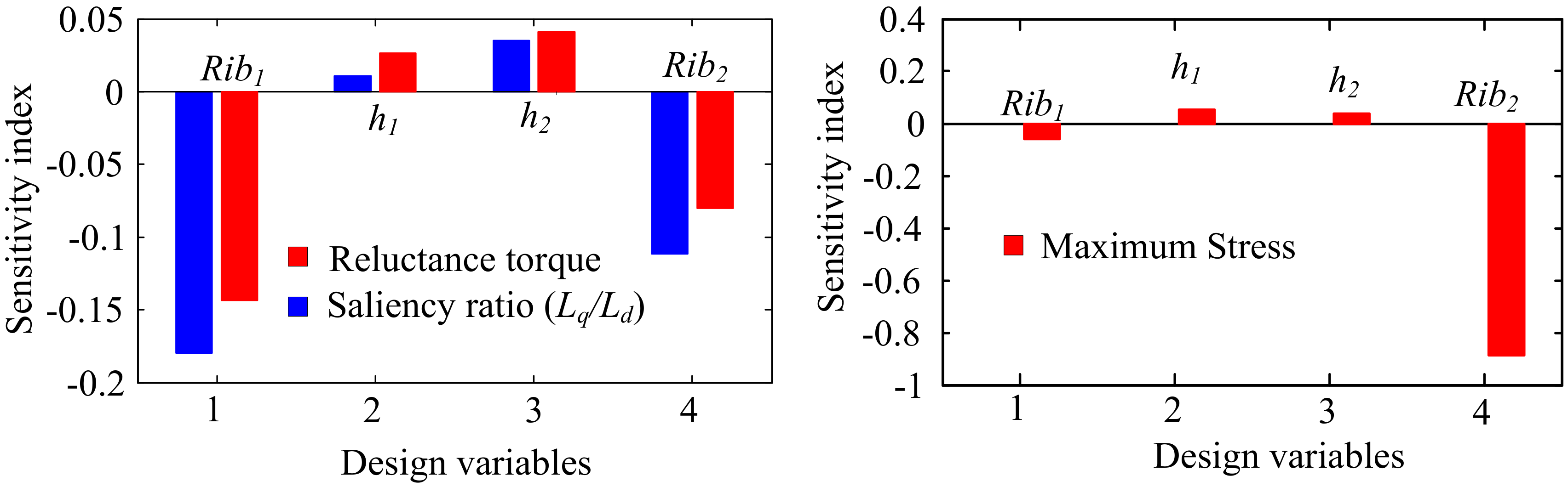
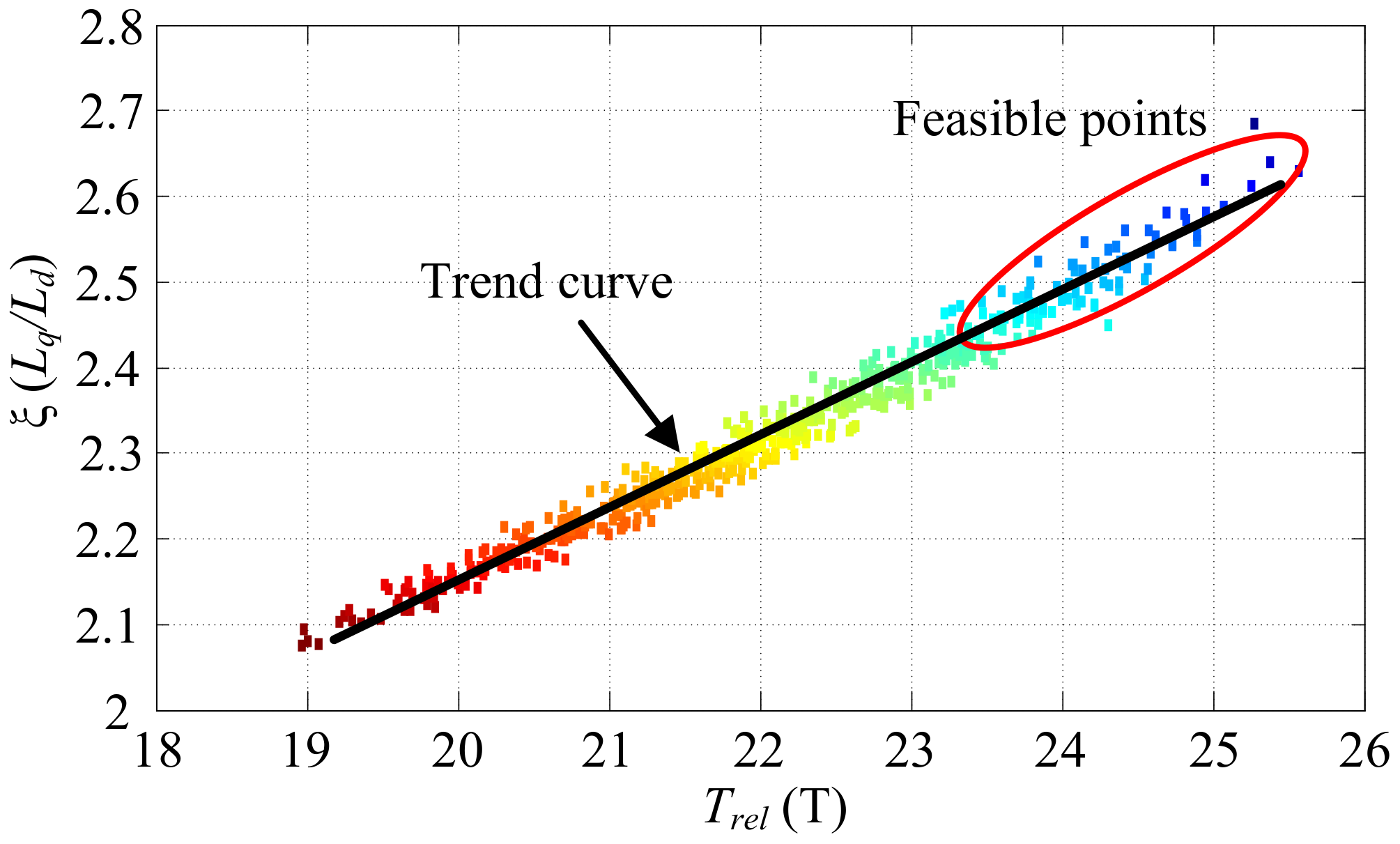
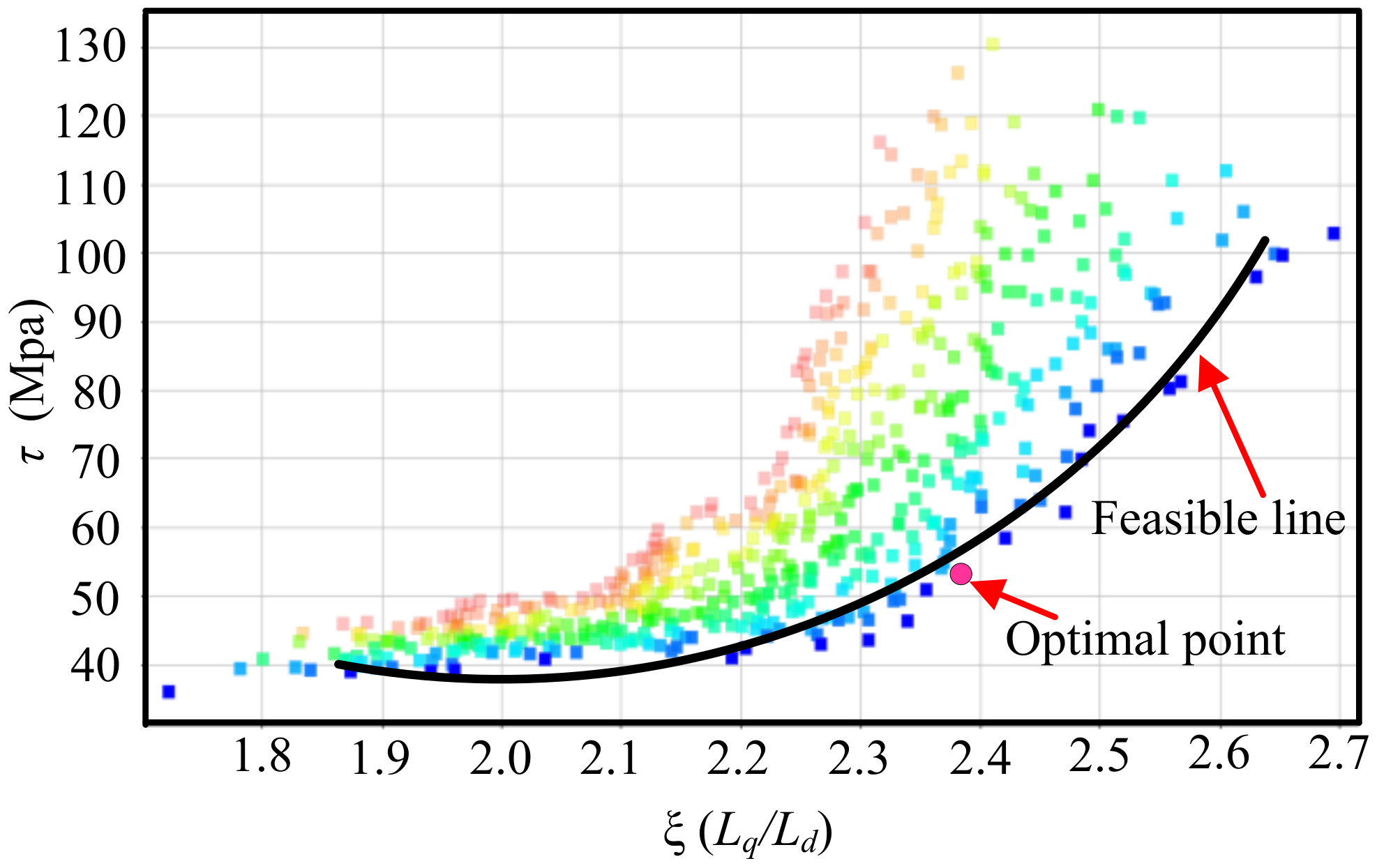
3.4. Optimization Step 1
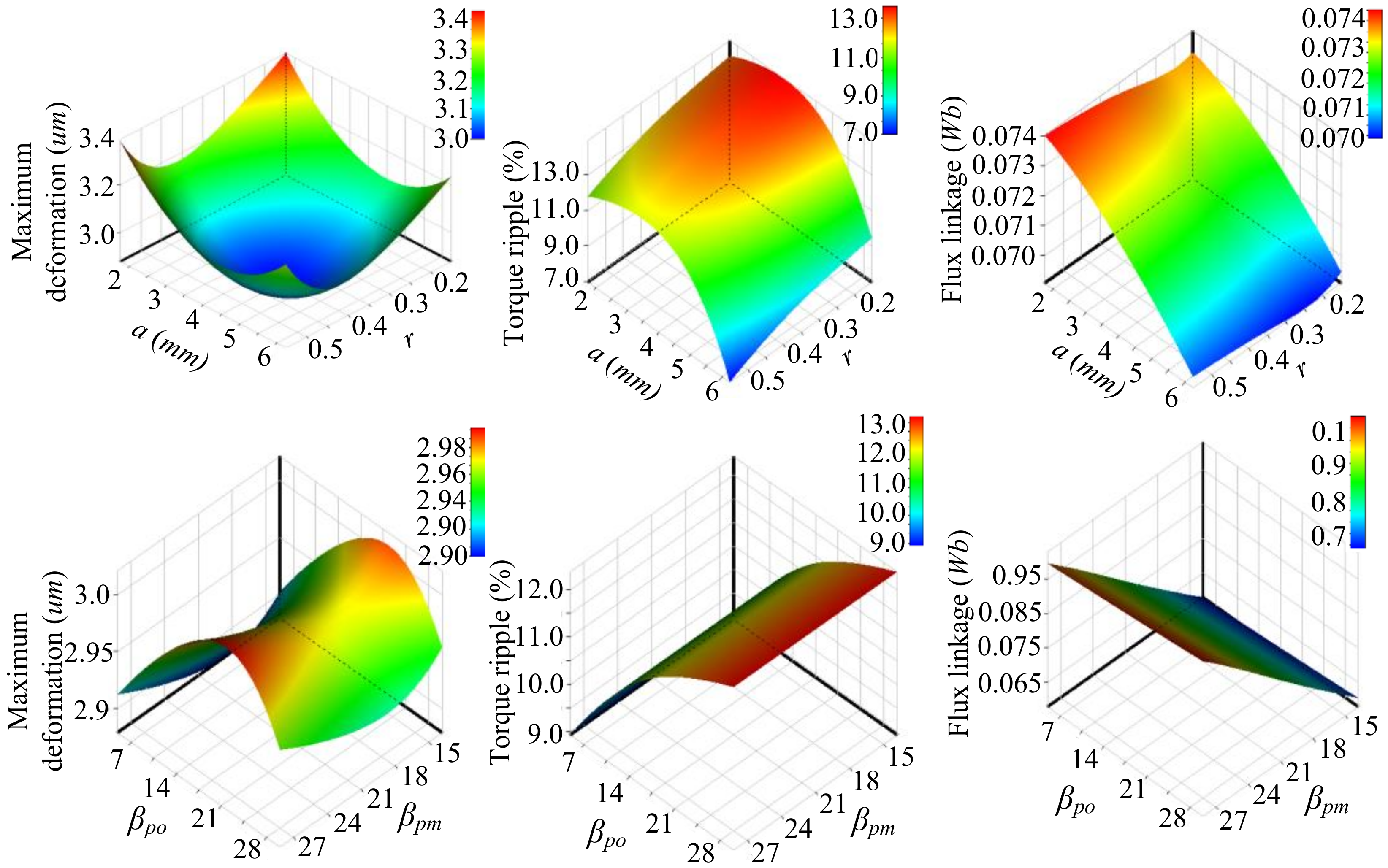
3.5. Optimization Step 2
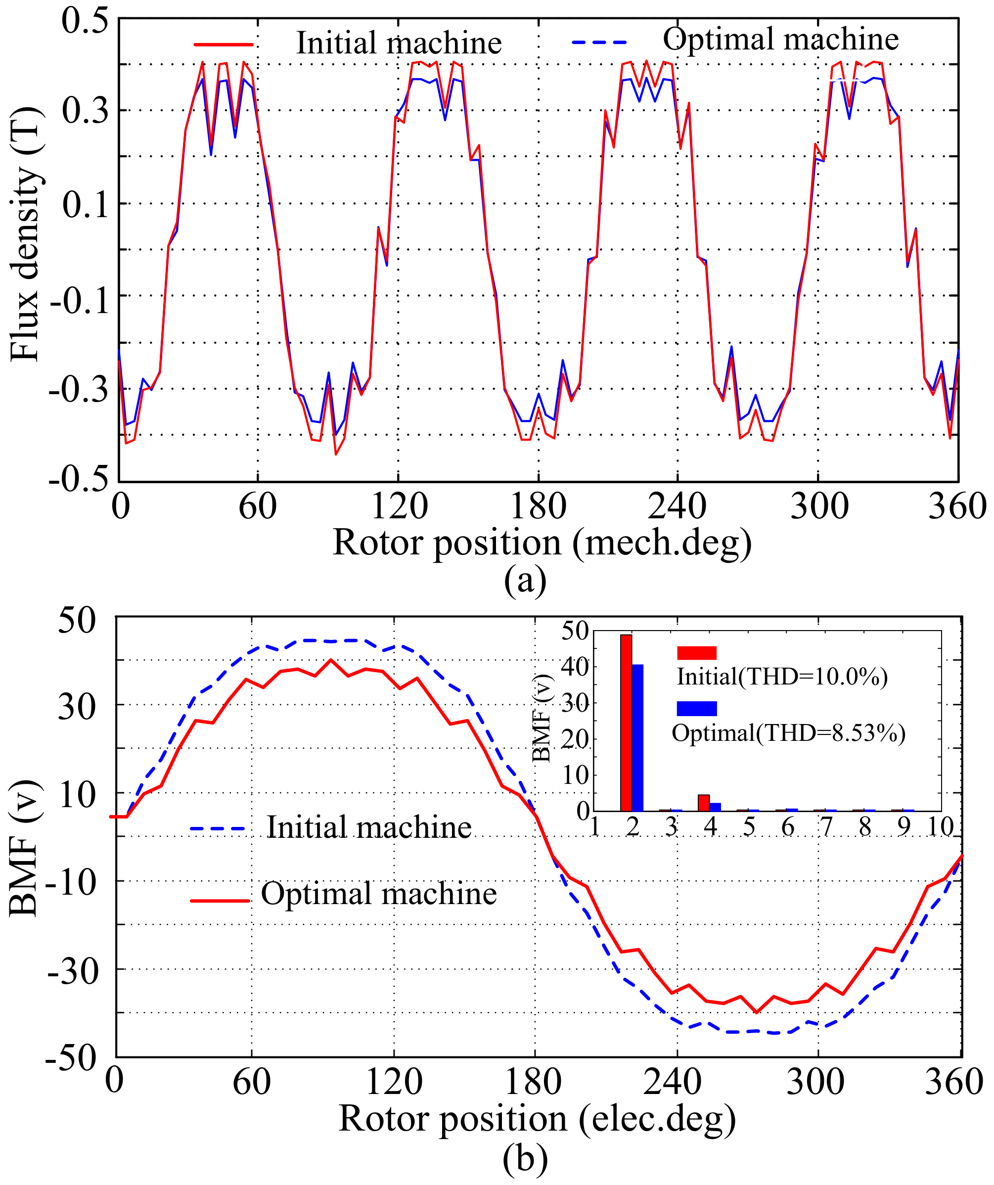
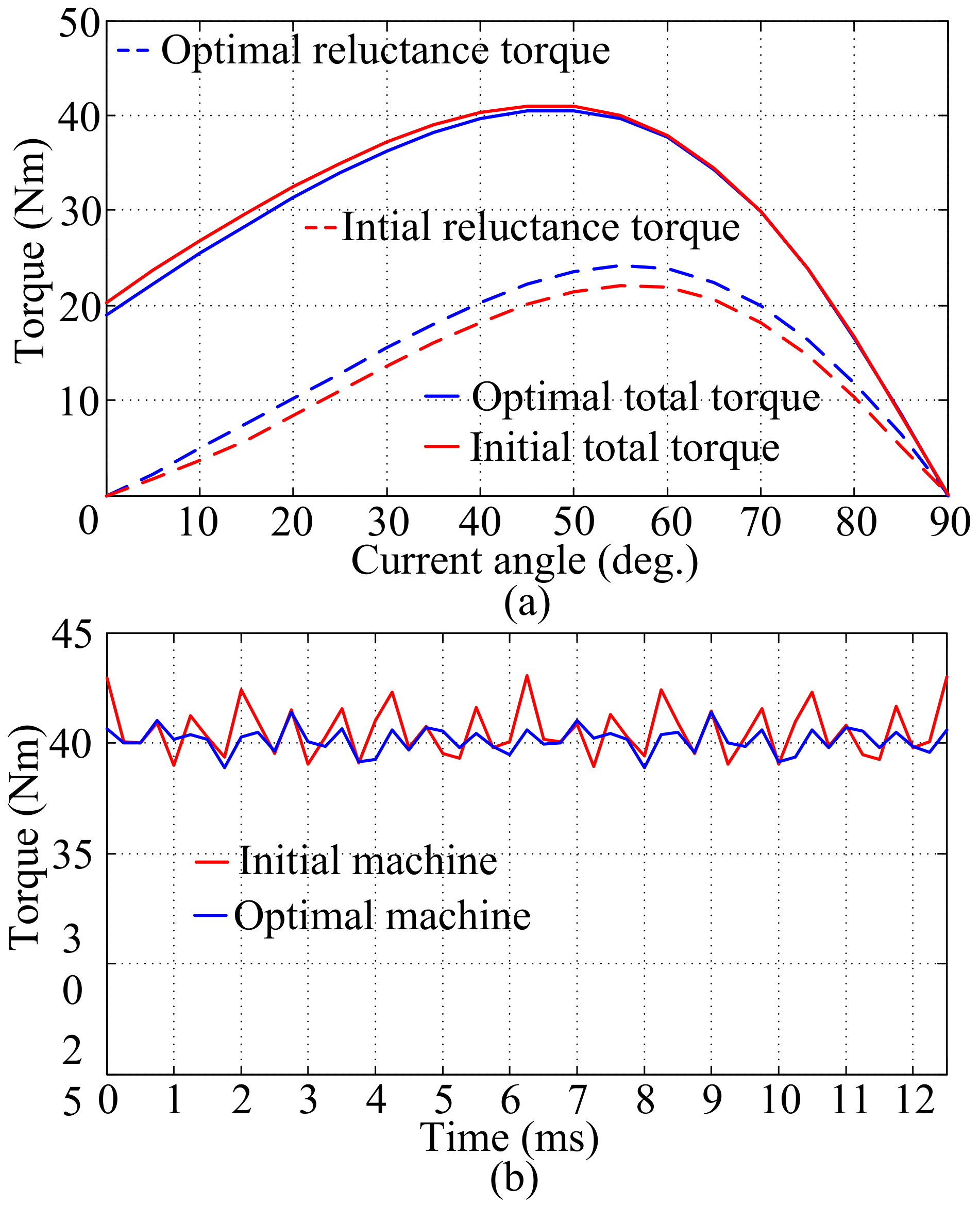
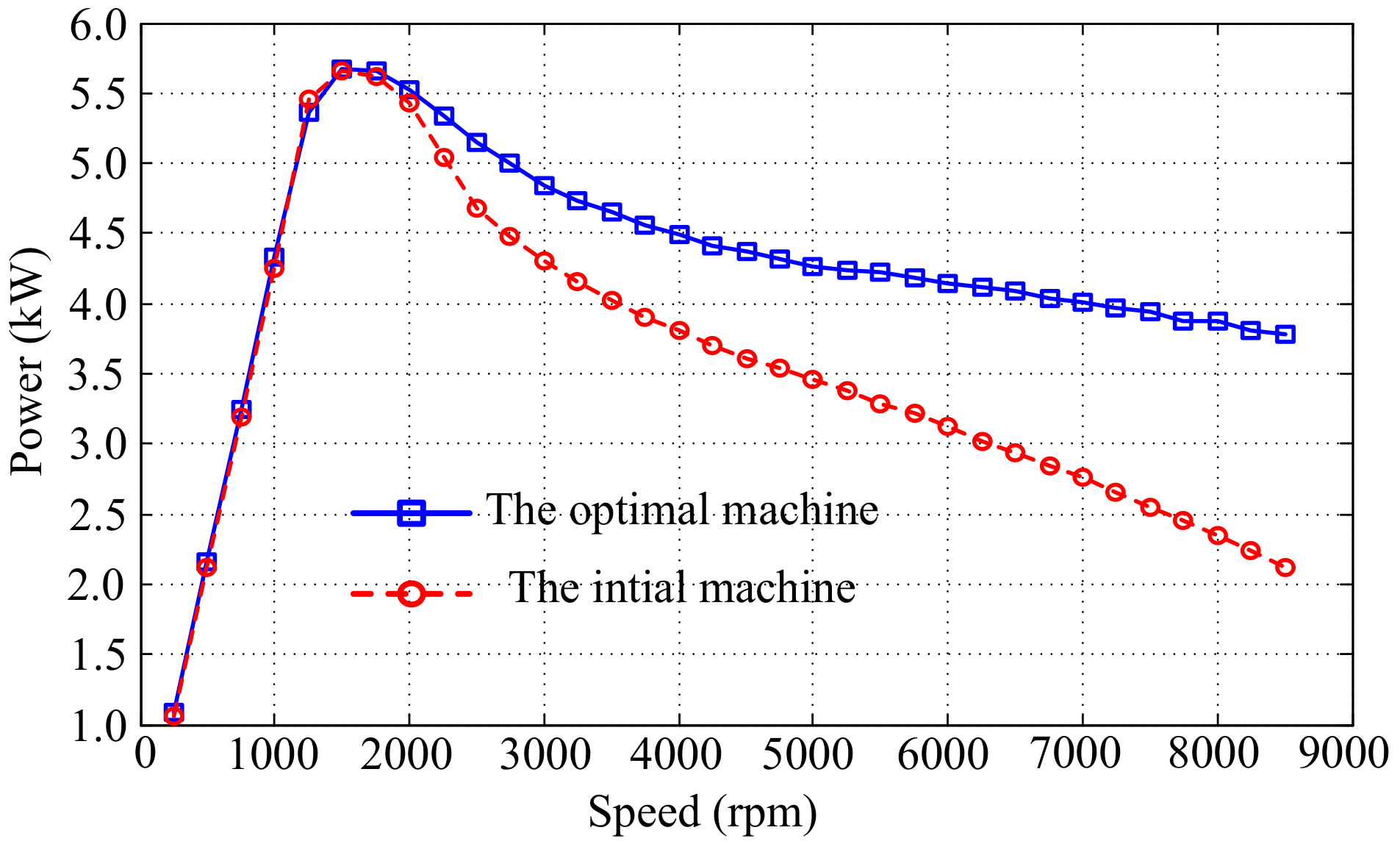
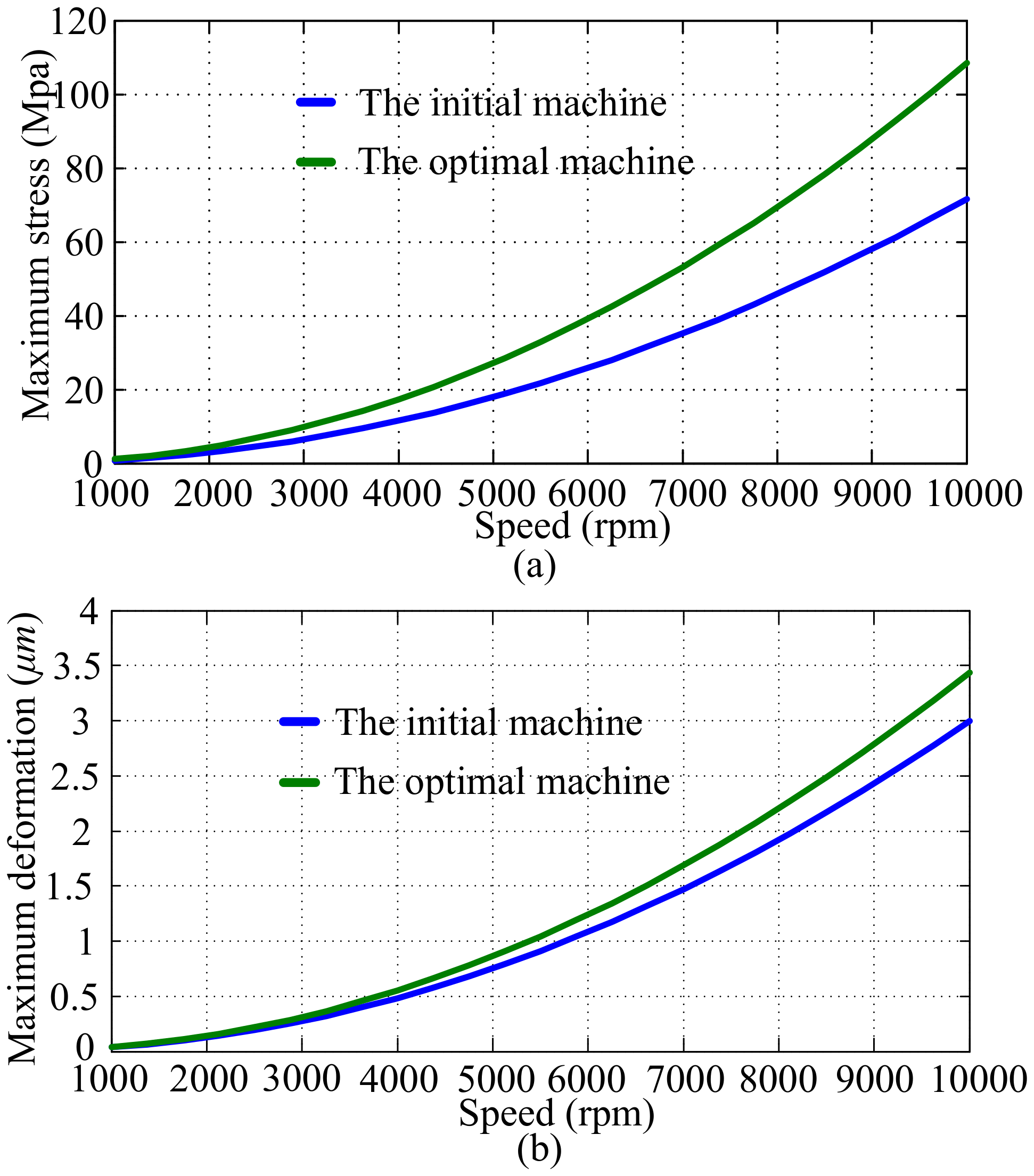
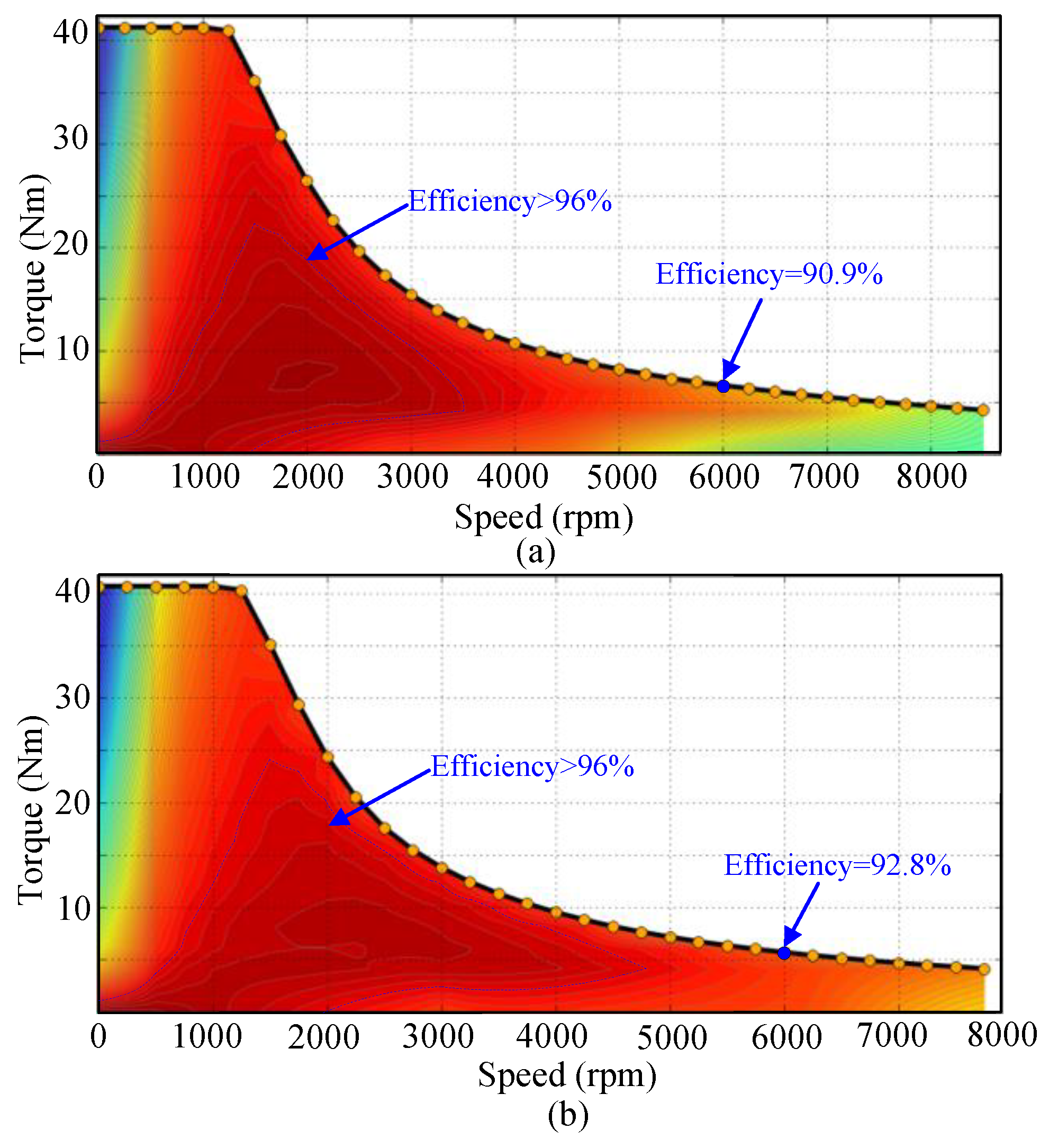
4. Performance Analysis
5. Conclusions
Author Contributions
Funding
Conflicts of Interest
Nomenclature
| Trel | Reluctance torque |
| T | Maximum stress |
| Tripple | Torque ripple |
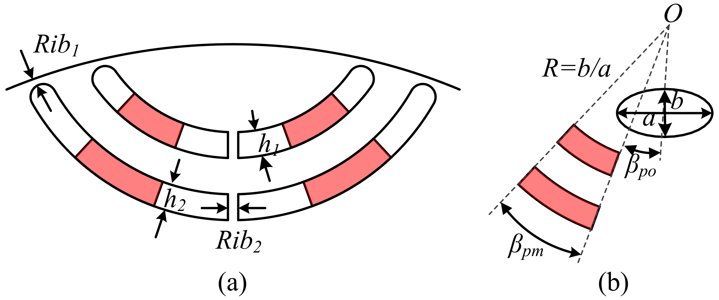
| Rib1 | Bridge width |
| h1 | Low barrier thickness |
| βpo | Starting angle of arc PM |
| R | Proportion coefficient of minor and major axis |
| a | Length of the major axis of the elliptical barrier |
| y/f(x) | Optimization objective |
| S(xi) | Sensitivity index |
| ξ | Saliency ratio |
| ψ | Flux linkage |
| γ | Maximum deformation |
| Rib2 | Rid width |
| h2 | Upper barrier thickness |
| βpm | Radian of the PM in barrier |
| xi | Optimization variable |
| Tout | Output torque |
References
- Cheng, M.; Hua, W.; Zhang, J.; Zhao, W. Overview of stator-permanent magnet brushless machines. IEEE Trans. Ind. Electron. 2011, 58, 5087–5101. [Google Scholar] [CrossRef]
- Zhu, X.Y.; Xiang, Z.X.; Quan, L.; Wu, W.Y.; Du, Y. Multimode optimization design methodology for a flux-controllable stator permanent magnet memory motor considering driving cycles. IEEE Trans. Ind. Electron. 2018, 65, 5353–5366. [Google Scholar] [CrossRef]
- Zhang, P.; Dan, M.I.; Demerdash, N.A.O. Saliency Ratio and Power Factor of IPM Motors With Distributed Windings Optimally Designed for High Efficiency and Low-Cost Applications. IEEE Trans. Ind. Appl. 2016, 52, 4730–4739. [Google Scholar] [CrossRef]
- Jung, J.W.; Lee, B.H.; Kim, D.J.; Hong, J.P.; Kim, J.Y.; Jeon, S.M.; Song, D.H. Mechanical stress reduction of rotor core of interior permanent magnet synchronous motor. IEEE Trans. Magn. 2012, 48, 911–914. [Google Scholar] [CrossRef]
- Chai, F.; Li, Y.; Liang, P.X.; Pei, Y.L. Calculation of the maximum mechanical stress on the rotor of interior permanent-magnet synchronous motor. IEEE Trans. Ind. Electron. 2016, 63, 3420–3432. [Google Scholar] [CrossRef]
- Zhu, X.Y.; Fan, D.Y.; Xiang, Z.X.; Quan, L.; Hua, W.; Cheng, M. Systematic multi-level optimization design and dynamic control of less-rare-earth hybrid permanent magnet motor for all-climatic electric vehicles. Appl. Energy 2019, 253, 113549. [Google Scholar] [CrossRef]
- Zhu, X.Y.; Huang, J.; Quan, L.; Xiang, Z.X.; Shi, B. Comprehensive Sensitivity Analysis and Multiobjective Optimization Research of Permanent Magnet Flux-Intensifying Motors. IEEE Trans. Ind. Electron. 2019, 66, 2613–2627. [Google Scholar] [CrossRef]
- Uddin, N.; Chy, M. On-Line Parameter Estimation Based Speed Control of PM AC Motor Drive in Flux Weakening Region. IEEE Trans. Ind. Appl. 2008, 44, 1486–1494. [Google Scholar] [CrossRef]
- Boldea, I.; Tutelea, L.N.; Parsa, L.; Dorrell, D. Automotive Electric Propulsion Systems with Reduced or No Permanent Magnets: An Overview. IEEE Trans. Ind. Electron. 2014, 61, 5696–5711. [Google Scholar] [CrossRef]
- Vagati, A.; Boazzo, B.; Guglielmi, P.; Pellegrino, G. Design of ferrite-assisted synchronous reluctance machines robust toward demagnetization. IEEE Trans. Ind. Appl. 2014, 50, 1768–1779. [Google Scholar] [CrossRef]
- Wu, W.Y.; Zhu, X.Y.; Quan, L.; Du, Y.; Xiang, Z.X.; Zhu, X. Design and analysis of a hybrid permanent magnet assisted synchronous reluctance motor considering magnetic saliency and PM usage. IEEE Appl. Supercond. 2018, 28, 1–6. [Google Scholar] [CrossRef]
- Bianchi, N.; Fornasiero, M.; Soong, W. Selection of PM flux linkage for maximum low-speed torque rating in a PM-assisted synchronous reluctance machine. IEEE Trans. Ind. Appl. 2015, 51, 3600–3608. [Google Scholar] [CrossRef]
- Limsuwan, N.; Kato, T.; Akatsu, K.; Lorenz, R.D. Design and evaluation of a variable-flux flux intensifying interior permanent magnet machine. IEEE Trans. Ind. Appl. 2014, 50, 1015–1024. [Google Scholar] [CrossRef]
- Zhu, X.Y.; Yang, S.; Du, Y.; Xiang, Z.X.; Xu, L. Electromagnetic performance analysis and verification of a new flux-intensifying permanent magnet brushless motor with two-layer segmented permanent magnets. IEEE Trans. Magn. 2016, 52, 8204004. [Google Scholar] [CrossRef]
- Limsuwan, N.; Shibukawa, Y.; Reigosa, D.D.; Lorenz, R.D. Novel design of flux-intensifying interior permanent magnet synchronous machine suitable for self-sensing control at very low speed and power conversion. IEEE Trans. Ind. Appl. 2011, 47, 2004–2012. [Google Scholar] [CrossRef]
- Nardo, M.D.; Calzo, G.L.; Galea, M.; Gerada, C. Design Optimization of a High-Speed Synchronous Reluctance Machine. IEEE Trans. Ind. Appl. 2018, 54, 233–243. [Google Scholar] [CrossRef]
- Lei, G.; Wang, T.; Guo, Y.G.; Zhu, J.G.; Wang, S.H. System-level design optimization methods for electrical drive systems deterministic approach. IEEE Trans. Ind. Electron. 2014, 61, 6591–6602. [Google Scholar] [CrossRef]
- Lei, G.; Wang, T.S.; Zhu, J.G.; Guo, Y.G.; Wang, S.H. System-level design optimization method for electrical drive systems-robust approach. IEEE Trans. Ind. Electron. 2015, 62, 4702–4713. [Google Scholar] [CrossRef]


| Parameters | Values | Parameters | Values |
|---|---|---|---|
| Rated power | 5.5 kW | Inner diameter | 116 mm |
| Rated speed | 1200 rpm | Stack length | 65 mm |
| Maximum speed | 10,000 rpm | Air gap | 0.5 mm |
| Rated torque | 40 Nm | Number of turns | 16 |
| Outside diameter | 195 mm | PM property | NdFeB (1.2T) |
| Materials | Density | Young’s Modulus | Poisson’s Ratio |
|---|---|---|---|
| kg/m3 | GPa | / | |
| PM | 7400 | 150 | 0.23 |
| Rotor core | 7650 | 200 | 0.3 |
| Steps | Objectives | Variables and Variation Ranges |
|---|---|---|
| 1 | Reluctance torque (Trel) Saliency ratio (ξ) Maximum stress (τ) | Rib1:0.5–2.0 mm Rib2:0.5–2.0 mm h1:1.5–3.5 mm h2:1.5–3.5 mm |
| 2 | Flux linkage (ψ) Torque ripple (Tripple) Maximum deformation (γ) | βpm: 14–28° βpo: 5–30° R: 0.2–0.5 a: 2.0–6.0 mm |
| Variables/Objectives | Initial Value | Optimal Value |
|---|---|---|
| a (mm) | 4.0 | 4.8 |
| R | 0.4 | 0.45 |
| βpm (°) | 24 | 20 |
| Βpo (°) | 20 | 16.2 |
| Tripple (Nm) | 11.8 | 7.2 |
| γ (μm) | 3.4 | 2.9 |
| ψ (Wb) | 0.091 | 0.082 |
© 2020 by the authors. Licensee MDPI, Basel, Switzerland. This article is an open access article distributed under the terms and conditions of the Creative Commons Attribution (CC BY) license (http://creativecommons.org/licenses/by/4.0/).
Share and Cite
Wu, W.; Chen, Q.; Zhu, X.; Zhao, F.; Xiang, Z. Electromagnetic–Mechanical Coupling Optimization of an IPM Synchronous Machine with Multi Flux Barriers. Energies 2020, 13, 1819. https://doi.org/10.3390/en13071819
Wu W, Chen Q, Zhu X, Zhao F, Xiang Z. Electromagnetic–Mechanical Coupling Optimization of an IPM Synchronous Machine with Multi Flux Barriers. Energies. 2020; 13(7):1819. https://doi.org/10.3390/en13071819
Chicago/Turabian StyleWu, Wenye, Qingzhang Chen, Xiaoyong Zhu, Fuzhou Zhao, and Zixuan Xiang. 2020. "Electromagnetic–Mechanical Coupling Optimization of an IPM Synchronous Machine with Multi Flux Barriers" Energies 13, no. 7: 1819. https://doi.org/10.3390/en13071819
APA StyleWu, W., Chen, Q., Zhu, X., Zhao, F., & Xiang, Z. (2020). Electromagnetic–Mechanical Coupling Optimization of an IPM Synchronous Machine with Multi Flux Barriers. Energies, 13(7), 1819. https://doi.org/10.3390/en13071819