Article

Low-Cost Solar Electricity Using Stationary Solar Fields; Technology Potential and Practical Implementation Challenges to Be Overcome. Outcomes from H2020 MOSAIC Project

1
Fundacion Tekniker, Polo Tecnológico de Eibar, Calle Iñaki Goenaga 5, 20600 Gipuzkoa, Spain
2
CENER (National Renewable Energy Centre of Spain), Ciudad de la Innovación 7, 31621 Navarra, Spain
*
Author to whom correspondence should be addressed.
Energies 2020, 13(7), 1816; https://doi.org/10.3390/en13071816
Submission received: 27 February 2020 / Revised: 1 April 2020 / Accepted: 6 April 2020 / Published: 10 April 2020
(This article belongs to the Special Issue Research on Solar Collector)

Abstract

:
At any time of the day, a spherical mirror reflects the rays coming from the sun along a line that points to the sun through the center of the sphere. This makes it possible to build concentrated solar power(CSP) plants with fixed solar fields and mobile receivers; that is, solar fields can be significantly cheaper and simpler, but challenging tracking systems for the mobile receiver need to be implemented. The cost-cutting possibilities for this technology have been under-researched. This article describes the MOSAIC concept, which aims to achieve low-cost solar energy by boosting the benefits of spherical reflectors while addressing their challenges. This new concept proposes to build large modular plants from semi-Fresnel solar bowls. One of these modules has been designed and is under construction in Spain. This article reports the main lessons learned during the design phase, describes the advantages and challenges of the concept, details the proposed routes to overcome them, and identifies the steps needed to develop a fully competitive industrial solution.

1. Introduction

Concentrated solar technology has the capacity to produce dispatchable green energy (both heat and electricity), which is a major advantage over other renewable energies [1,2]. In recent years, its production costs have been substantially reduced, but there is a pressing need to reduce them further in order to expand its market penetration. Reducing costs and maintaining or increasing energy conversion rates is the only way to reach this goal, but achieving both simultaneously is challenging [3].
Higher efficiency requires higher operating temperatures, which also increase the storage capacity of the systems and, therefore, their profitability [4,5]. However, achieving higher temperatures requires higher concentration ratios, which, in turn, requires a larger investment to pay for more precise tracking systems, more sophisticated materials, etc. Most of the costs of high-concentration solar technologies come from the solar field and especially from the sophisticated tracking systems needed [6]. The MOSAIC project [7] proposes a new plant configuration that provides high concentration ratios, even though it proposes a fixed solar field with great potential for reducing its costs. Furthermore, it proposes to group several of these concentration units in a modular plant, which would provide additional advantages.
CSP plant power blocks and storage systems are more cost-effective the larger they are; therefore, the plants tend to be large in size (100 MW or larger). For today’s central receiver plants, this means huge towers and thousands of heliostats located at great distances (>1 km). This has cost implications, as it requires very demanding tracking and canting accuracies and very rigid structures. Moreover, it also involves significant atmospheric attenuation, which imposes limits on the size of the plant. However, it should be borne in mind that the aim is to achieve high temperatures, and therefore, high concentration ratios, which does not necessarily imply large concentrators since the concentration ratio is a dimensionless parameter. In contrast, the MOSAIC configuration achieves high powers (large collection areas) in a modular way, linking a number of modules, each with low atmospheric attenuation and moderate accuracy requirements.

2. The Current State of Research

Unlike parabolic mirrors, spherical concentrators (or solar bowls) can be fixed using a mobile receiver [8]. Hence, these systems are also known as SRTA (stationary reflector/tracking absorber). This is because a spherical mirror always focuses the solar radiation along a line passing through the sphere center and pointing to the sun (see Figure 1) irrespective of the position of the sun relative to the mirror. This concentrated flux is not uniform and grows from the surface of the mirror to the midpoint of the bowl’s radius.
Despite its well-established [9] cost reduction potential, the concept has been poorly studied. A small number of prototypes have been built at a relevant scale, and limited results have been published. According to Goodman [10], Adams [11] already recorded a stationary spherical reflector made of 40 flat glass facets built in Middle Colaba, Bombay, India, as early as 1878. Other researchers [12] refer to the 1928 Berland patent [13] as the birth of the technology.
Optical characteristics of the SRTA, their implications on the minimum receiver size, and the axial variation of the concentration ratio were studied in detail by Steward and Kreith [8]. At the same time, Kreider [14] analyzed its thermal performance and identified key design parameters.
Fixed reflectors make it possible to build very large mirrors, and to even integrate them in a building roof (see examples in Figure 2). However, this paper will focus on stand-alone configurations best suited for large-scale electricity production.
In the 1970s, solar bowl programs were launched in the USA, France, and Israel and new developments started in India in the 1980s and Europe in the 1990s:
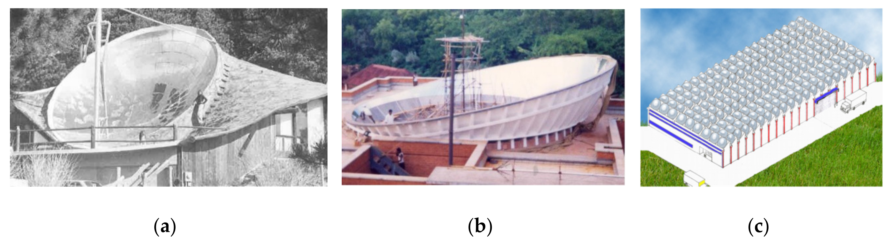
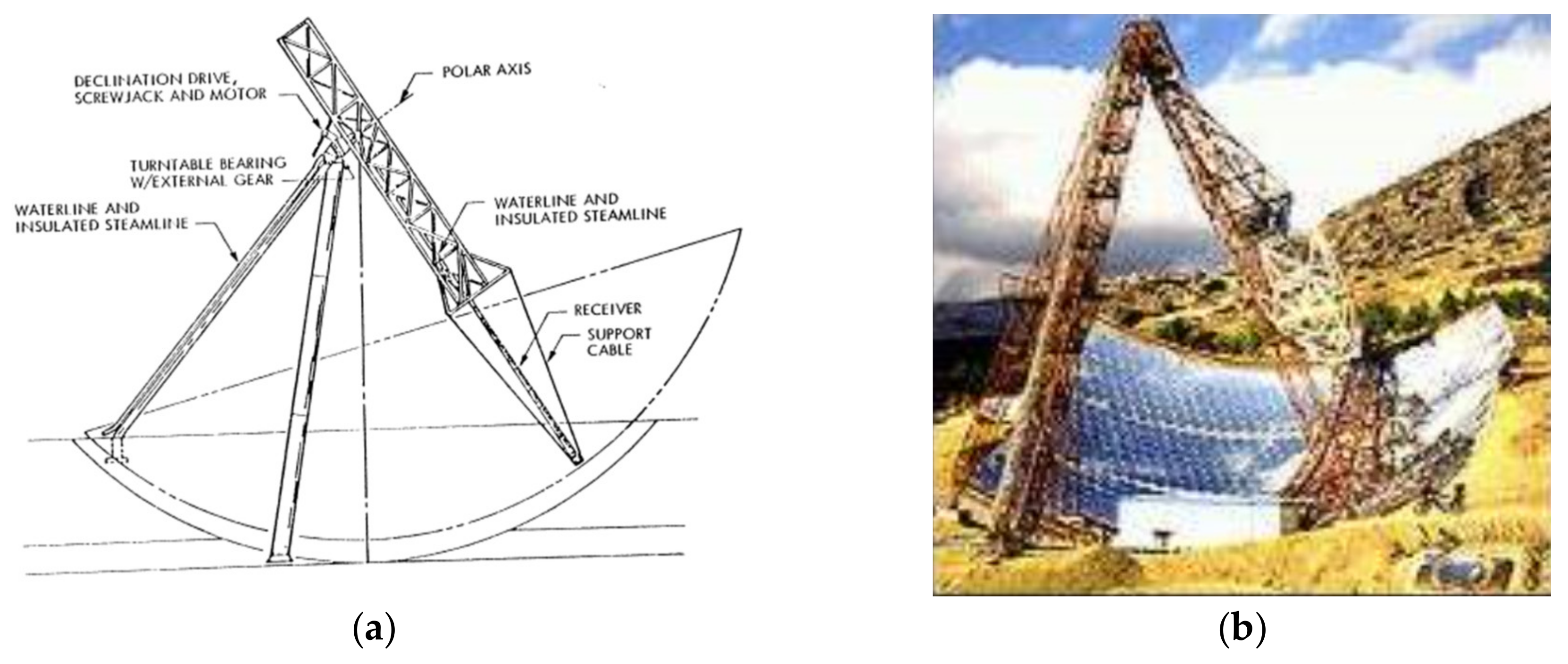
  • USA: The United States Department of Energy (DOE) DOE launched the Crosbyton solar power project (CSPP), and the analog design verification system (ADVS) began tests in 1980 in Crosbyton (Texas). The reflector of the ADVS was a spherical bowl with 19.8 m aperture diameter, 60° semi-rim angle, and was tilted 15° [16]. Its receiver was 5.7 m long made of Inconel alloy 617, producing superheated steam at 538 °C. The system was intended to act as a testbed for the design of a 5 MW hybrid solar/fossil fuel power plant. Such a plant would have had 10 bowls, each with 60 m aperture diameter, but after the test period, the ADVS was dismantled.
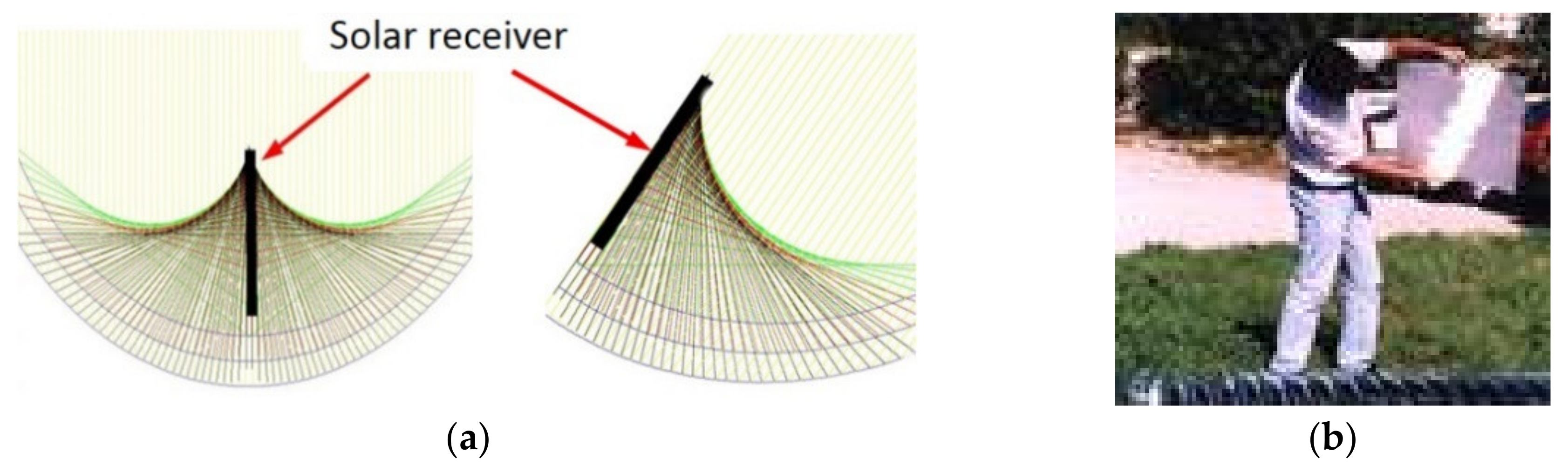
  • France: CNRS (Centre National de la Recherche Scientifique) developed the Pericles project to study SRTAs for the vicinity of the equator or tropical areas. A test bowl was built in Marseilles, France, and later rebuilt in Recife, Brazil. The system was operational in 1980. It had a 10 m aperture diameter, 120° rim angle, and no inclination. It was known as mini-Pericles since 30–40 m diameter bowls were studied within the project. The bowl included an additional mobile element (rotary visor) to reduce shadows and improve efficiency in the early morning and late in the day [17]. Gilotherm TH oil was used as Heat Transfer Fluid (HTF) up to 330 °C.
  • Israel: Several SRTA versions were built in the 1970s in Haifa, Israel, at the Technion–Israel Institute of Technology. The largest prototype had a 10 m diameter dish that produced steam at 300 °C, but no public report has been found; it was operational in 1979. Design, construction, and testing of a smaller version (2.52 m diameter) operated with PAZTHERM 22TM are described in [18]. Other papers describe successive versions in the range of 2.4 m to 8.7 m aperture diameter [12]. Ref. [19] shows a video of a recent SRTA test bench.
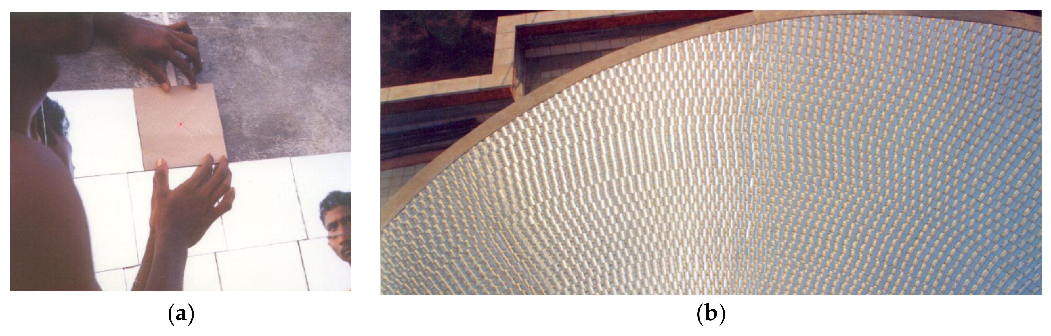
  • India: The first dish, with a 3.5 m aperture diameter, 120 rim-angle, inclined to 12° was developed in Auroville, Tamil Nadu, India, was already reported by Harper in 1982 [20]. It used small flat glasses glued to concrete. In the 1990s, a much larger solar bowl was integrated into Auroville’s community kitchen [15]. This new project involved not only Harper but also other technology enthusiasts who had been involved in previous projects in France or the USA, such as Goodman, Authier, or Debilly. They considered that solar bowl technology was relatively simple and low-cost and that it had the potential to use labor more intensively than capital, making it suitable for developing countries. In fact, the system had been supplying steam for cooking since 2001. The solar kitchen included a spherical bowl with 15 m aperture diameter, 120° rim angle, and 12° tilt angle. During 2001–2002, the system was tested using oil (above 200 °C) as heat transfer fluid (HTF). Later it was switched to a ‘water only’ system more suitable for cooking and easy to use; it produced steam at 150 °C.
  • Europe: The European Commission funded Phase 1 of a research project (1996–1999) that developed a prototype [21] producing hot air at 850 °C in Crete, Greece. The original concept aimed to produce 1 MW, but the prototype developed in Phase 1 was downsized. The prototype consisted of a reflective surface with a radius of curvature of 30 m (a 47° wide segment in the north-south direction and a 60° wide segment in the east-west direction) that supplied heat to the 35 kWe solar-gas turbine. The volumetric receiver with a secondary concentrator followed the concentrated solar flux at a distance of 14.7 m from the surface of the mirrors. As two-thirds of the mirror costs were the civil works associated with the construction of the bowl, a revised concept was conceived for Phase 2, which included a flat fixed Fresnel mirror. The most relevant prototypes to date are summarized in Table 1.
As shown in the Crete project, large bowls installed at relatively high latitudes require huge civil works, while Fresnel configurations have the potential to be cheaper and easier to build. Figure 3 shows how a series of concentric spheres of different radius continue to concentrate the solar flux into a single focal line that passes through the center common to all the spheres and points to the sun. This is the basis for the design of Fresnel-type SRTAs. Larbi [22] and Sánchez [23] studied the optical design characteristics of different Fresnel-type configurations trying to reduce the investment in reflector infrastructure with minimum reduction in energy delivery and concentration ratio. However, so far, no relevant prototype has been built, but only small models (see Figure 3).
SRTAs have not only been developed for solar electricity production, but different developments [8,12,15] have focused on solar heat production for a variety of uses. The MOSAIC configuration could also be applied for these purposes, especially to supply solar heat to industrial installations.

3. Materials and Methods

The MOSAIC project investigates a new concept of SRTA. The static reflector is not a continuous bowl, but a semi-Fresnel design is proposed. The proposed cable-based tracking system is also new. These innovations are intended to reduce costs. Furthermore, it is expected that in the future, its deployment in the field will be easy and fast thanks to the modularity of the concept. In summary, the system pursues the following objectives:
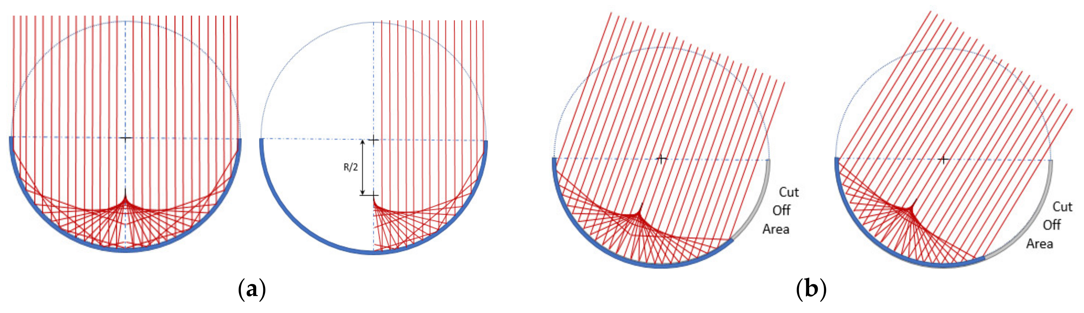
  • Low costs because of the fixed solar field. Eliminating the drives of thousands of heliostats eliminates the most expensive elements of the solar field and those that require the greatest resources for their maintenance. In addition, the proposed Fresnel configuration limits the main drawbacks of previous SRTA configurations (huge civil works costs, high wind loads, etc.).
  • High concentration ratios and high thermal efficiency of the system. The system allows concentration ratios much higher than those of the parabolic trough collectors and maximum concentrations in the upper part of the receiver close to those of the solar towers.
  • High operating temperatures allow high efficiency of the thermodynamic cycle that is fed by the system. Additionally, higher operating temperatures reduce the size of storage tanks and improve the cost-effectiveness of the thermal storage system, contributing to lower electricity costs.
  • Scalable plants to any power output as a result of the modularity of the concept. The maximum size is not limited, and it is possible to think of plants with large power blocks that are more efficient and large centralized thermal storage systems that are more cost-effective. If needed, smaller plants can also be designed to produce electricity or to supply heat to industrial processes.
In turn, to achieve all these potential advantages (low costs, high efficiencies, and cheap energy storage), a system that moves the receiver must be developed, which introduces important challenges to be solved. The next section also describes other possible drawbacks of SRTAs and the strategy followed to minimize them. A 3D view of a MOSAIC module is shown in Figure 4.

4. Results and Discussion
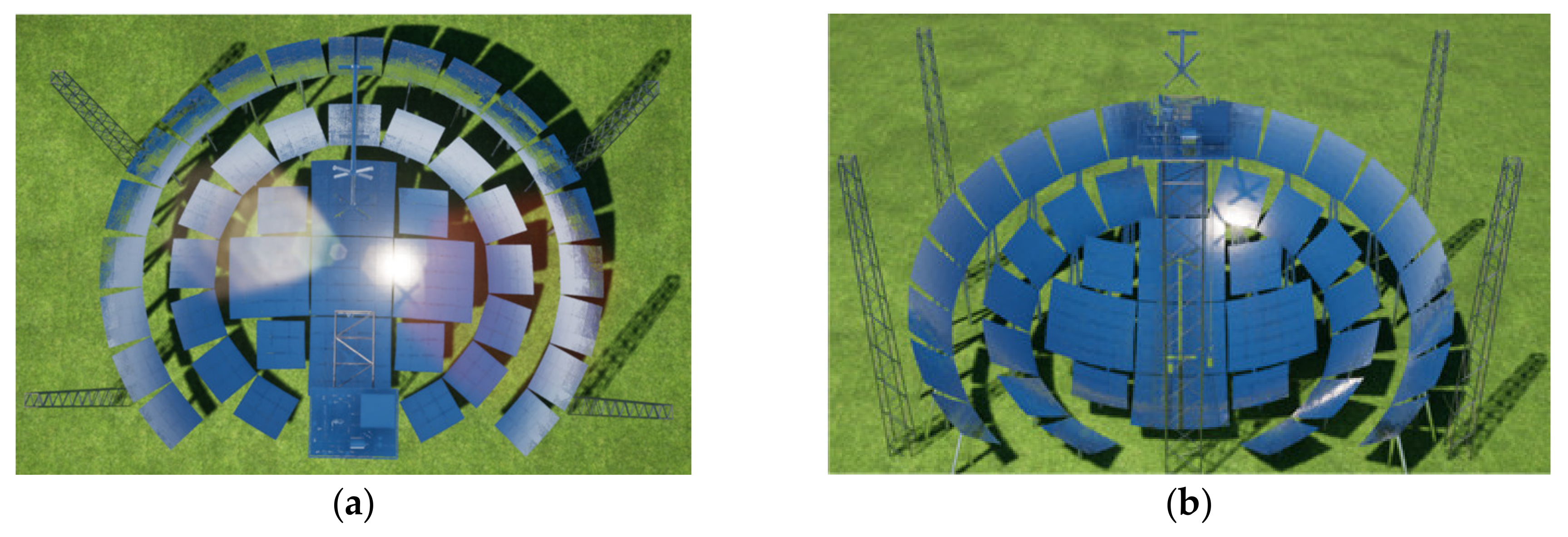
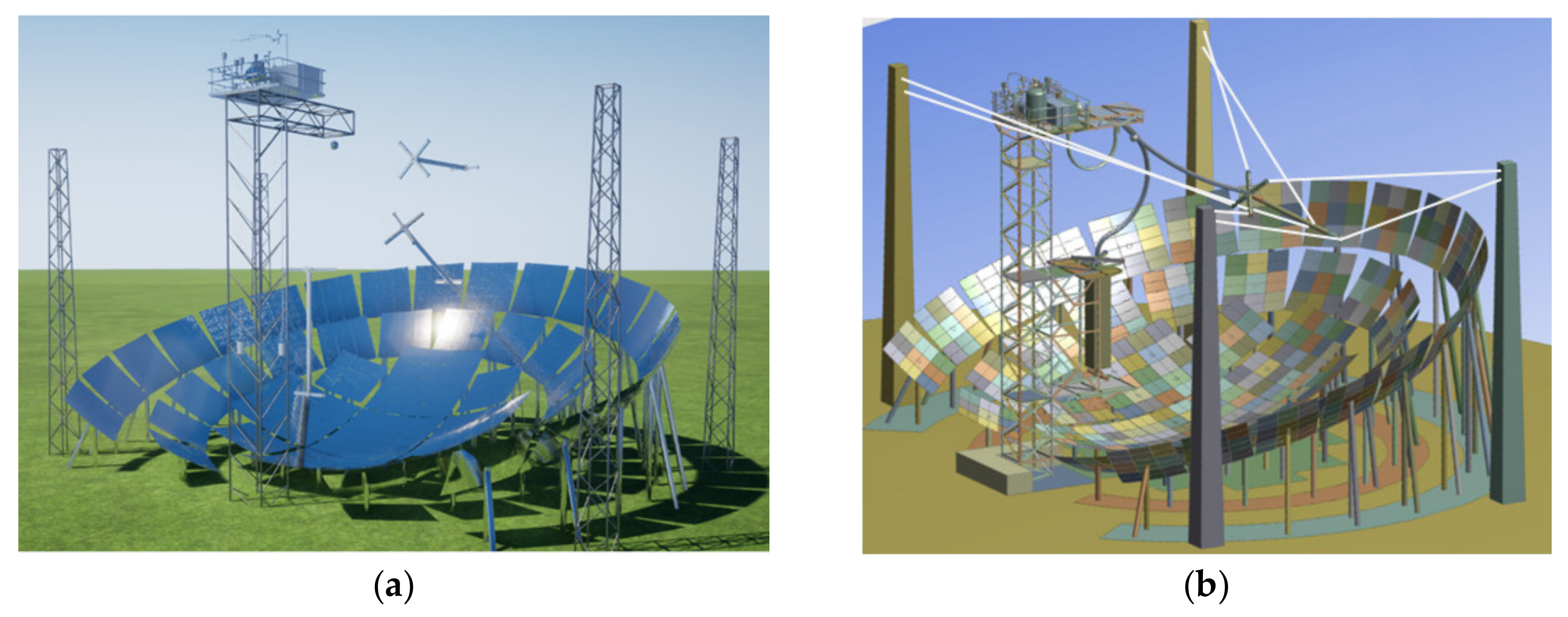
Given the novelty of the MOSAIC approach, there are specific features and challenges that need to be further studied, tested, and validated. In order to gain the required experience, a complete prototype has been designed and is being built in Spain. The following describes the configuration of the system and of the various components, their main characteristics, and the reasons that led to the choice of that particular design

4.1. Solar Field.

As in other SRTAs, the solar field is fixed. This opens up great savings potential, as no drives, wiring, or trenching are required for the solar field. However, previous projects [21] have shown that these savings can be compromised when trying to build systems of relevant size for large-scale power plants.
A key parameter to define in order to optimize an SRTA is its tilt angle, which depends mainly on the latitude where it will be installed. As presented in a previous study [7], most interesting latitudes are above 30°, which can lead to rather high tilt angles in other to minimize cosine effect.
High tilt angles are not desirable for large SRTAs, as they result in higher and steeper solar field structures that are more exposed to strong winds (concentrators are fixed and cannot be moved to the stow position). This requires high, heavy-duty structures or huge excavations. Elevated parts can also also be a problem regarding accessibility for maintenance and repair.
The MOSAIC project addresses this problem through a Fresnel configuration. To ensure that most of the solar field is close to the ground, even with minimal or no excavation, the concentrator uses a set of concentric spheres. In addition, the discontinuities between spheres allow access corridors to the entire solar field. The long continuous ring-shaped surfaces also open up the possibility of developing automatic cleaning devices that slide over the mirrors, thus simplifying cleaning, which is the most resource-consuming maintenance operation in a CSP plant.
The optimal configuration must balance the costs of the system and its optical efficiency. As explained by Sánchez [23], this economic optimum is not achieved with a flat Fresnel configuration but with a "semi-Fresnel" configuration (see Table 2).
Depending on the latitude, terrain characteristics, expected wind speeds, etc., a different optimal module configuration can be defined. A MOSAIC module will always comprise a central bowl and additional rings corresponding to increasingly large concentric spheres separated by corridors (see Figure 5). Note that the descriptions will consider plants located in the northern hemisphere.
Table 2 shows that each mirror contributes unevenly. The mirrors in the center provide more energy. The mirrors on the top (north side of the module) will require higher supporting structures but will contribute more in winter while the lower mirrors (south side) will contribute more in summer. All this must be considered when deciding which mirrors will be implemented to obtain a balanced production throughout the year at minimum cost. Finally, practical considerations such as the width of the passageways have been considered to define the optimal configuration.
The design process defines the optimal size, the tilt angle, the number of curvatures (spheres), the width of the rings, the part of the collector to be excavated, and the part to be installed above ground level, the mirror areas to be implemented, etc. Given the cross-influences of the different variables and the practical constraints of design, the optimization process is not linear but iterative.
The first analysis led to modules with an aperture radius of 20 m, providing a maximum thermal power of around 500 kWt. Larger modules were also considered; these designs included a central bowl and three additional rings (see Figure 5b). The tilt angle would be 7.1° at latitudes of 30.5°.
The mirrors themselves also have particular requirements and impose additional restrictions. SRTAs require spherical mirrors, i.e., mirrors that are curved in two axes. Even in the case of relatively large spherical modules, their curvatures will be relatively strong compared to the facets of heliostats. This implies a greater complexity in their design and manufacture, which, in turn, limits the maximum size of the spherical mirror to be manufactured.
Auroville’s solar bowl [15] addressed this problem by discretizing the reflective surface into a large number of small flat mirrors (see Figure 6). This slightly limits the concentration ratio, but above all, greatly increases the installation and canting time required. The Crete project [21] fixed thin (flexible) mirrors on a spherical concrete surface, where they were shaped, but ended up corroding in a short time. In addition, the mirrors, once attached, cannot be readjusted if required during their lifetime.
In addition, hot spots (points of high concentration) will appear on the mirrors due to secondary reflections. Taking all this into account, Rioglass has developed tailored mirrors for the MOSAIC concept that have passed the laboratory tests. The mirrors to be manufactured have a surface of 1 x 1 m and a spherical geometry with the radius of the corresponding sphere. Accordingly, the width of the rings can only have discrete values (e.g. 1, 2, or 3 m).
With all this in mind, a prototype of appropriate size was defined to validate the concept and is under construction in Sangüesa, Navarra, Spain (latitude 42.59°). It includes a central bowl, and two incomplete outer rings tilted 15°. In total, there will be 600 mirrors of 1 m2 (mirrors from the south that contribute less will be eliminated). The radii of curvature of the corresponding spheres are 15, 16.1, and 17.9 m, and together, they provide a peak thermal power close to 300 kWt. The aperture diameter of the system will be 30 m.
In order to optimize manufacturing costs, we have also aimed to use identical structures for different areas of the solar field. To this end, all mirrors will be installed in 3 x 3 or 5 x 5 mirror modules, which will then be lifted into position (see Figure 7). Depending on wind conditions and soil characteristics, future plants could implement a partially buried solar field. For the prototype, all mirrors will be installed in structures above ground level, which will facilitate any re-shaping or maintenance work, and access to the back of the mirrors.
Another remarkable effect of SRTAs is that they do not have the ability to defocus the solar field. That is, a concentrated solar flux will always exist unless mirrors are covered. In contrast, the distribution of concentrated solar flux is known and is fixed for each day and time of the year. Therefore, it has to be guaranteed that no one can access this elevated area and that no element except the receiver passes through the areas of maximum flux, either in normal operation, during start-up, and shutdown, in emergencies or during maintenance operations.
One last key advantage of the proposed configuration should be highlighted. All other CSP plants require complex assembly systems and optical devices to regularly verify that the reflected flux is correct. In contrast, the optical quality of the SRTAs is easily verifiable on-site, as all the mirrors in the field have a common focal point. Therefore, a person placed at that point (common center of the spheres) can validate the entire solar field in a single step and without the need for complex devices.

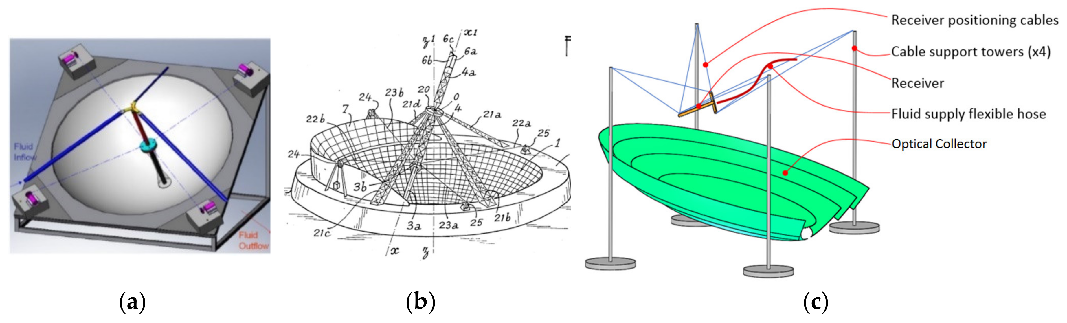
4.2. Tracking System.
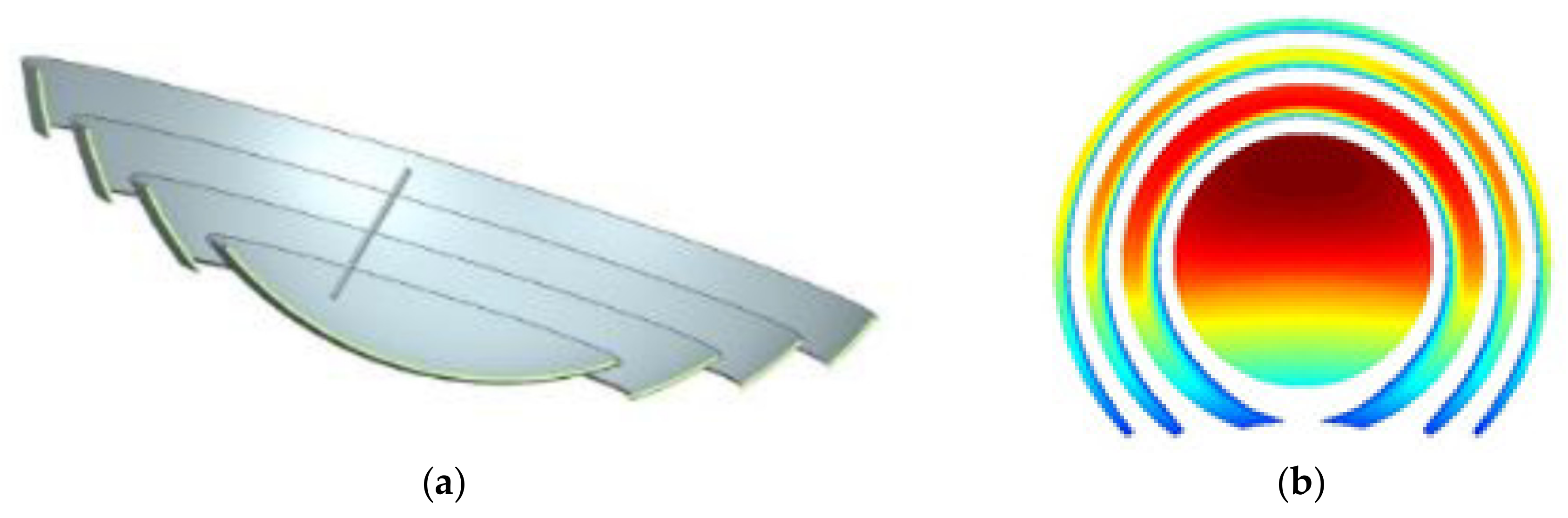
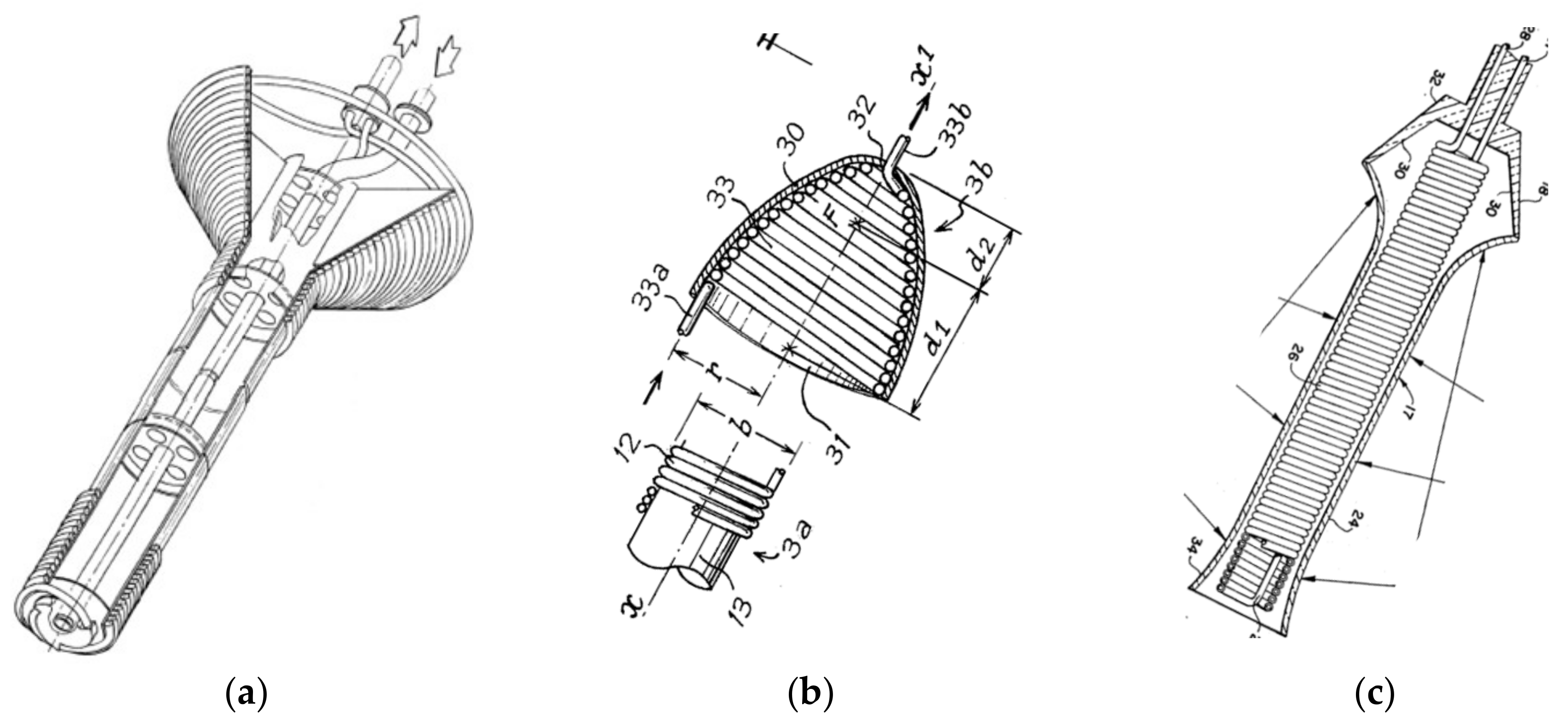
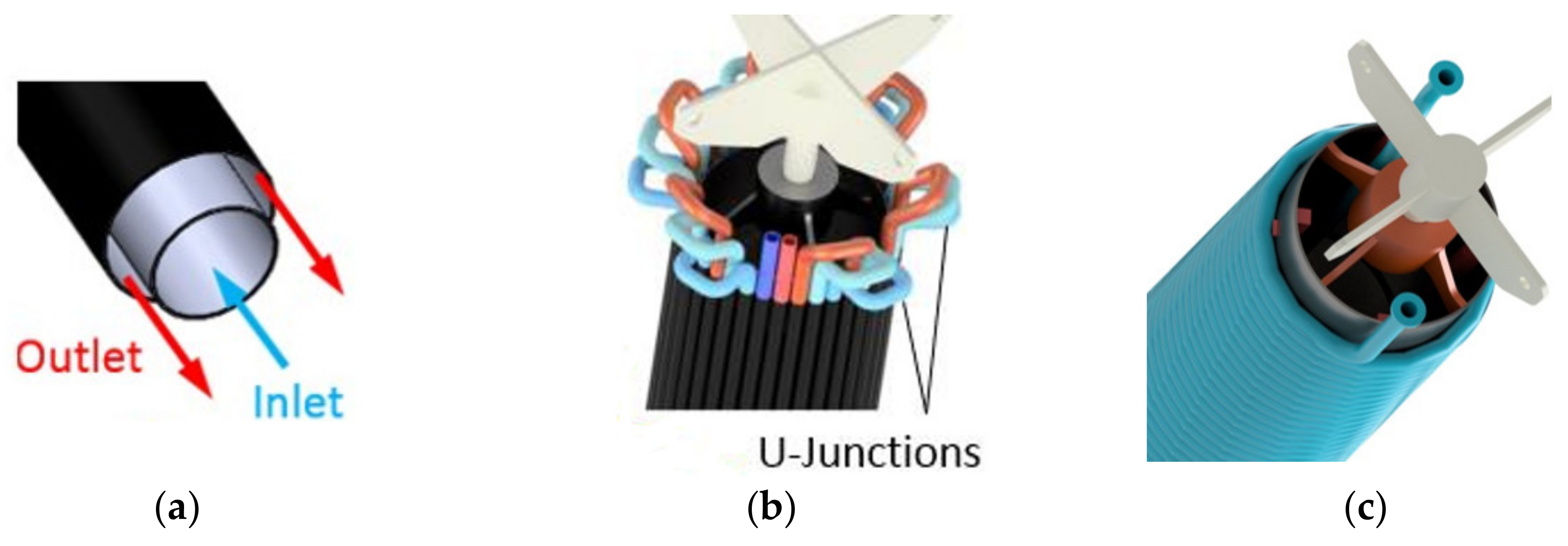
As the solar field is fixed, only one tracking system will be needed for each module, which will move the receiver to track the sun. This can lead to a reduction in investment costs, as well as fewer failures and maintenance operations.
In the past, SRTA tracking systems have relied on heavy and rigid structures to ensure a fixed point in the center of the sphere, where a beam is supporting the receiver pivots during its movement. They used a tripod-type configuration, such as those described in Figure 8. This tripod must be rigid to keep the center of rotation of the receiver in place. The arm holding the receiver and the receiver itself must also be rigid enough to ensure precise positioning, even for the highest elevations of the receiver (sunrise or sunset). The weight and cost of these stiff structures increase quadratically to the size of the system. In fact, projects implementing large solar bowls such as those in Crosbyton or Crete showed the high cost of the structures required to support the receiver.
In the MOSAIC project, a new approach is adopted. The receiver will be suspended by several metallic cables, which will define its position in the air above the fixed mirror. These cables will be pulled from four light towers to correctly position and orient the receiver during the day.
The use of cables to operate the receiver had already been proposed [12,17], but those designs included a tripod to hold the receiver (see Figure 9). That is, the cables did not hold the receiver but simply pulled it to make it pivot around the center of the sphere. Therefore, they did not use the full potential of the cable drives.
The use of cables to drive and hold the receiver opens up new opportunities for cost reduction. Cable-driven handling solutions have inherent advantages, such as the ability to store cables on reels, provide large workspaces, relatively low moving masses, or low manufacturing costs. However, the accurate positioning of the element to be moved presents several challenges due to the compliance of the cables and supports, which operate under considerably different tensions depending on the position of the moving part, as well as due to the uncertainties of the nominal geometry of the plant. Therefore, a closed-loop controlled system is required to position the receiver in the desired poses accurately.
Unlike solar tower systems, the entire solar field of a module behaves like a single concentrator (it produces a solar flux that is defined by the position of the reflectors, the location of the site, and the solar time) and a single receiver must be positioned. As a result, closed-loop controlled systems can be implemented, as long as the actual position of the receiver can be determined. The proposed solution includes a position closed-loop control system based on artificial vision. Kortaberria et al. anticipated a possible implementation in a previous paper [25]; this allows for additional savings to be made since the tracking errors can be measured and corrected. That is, it is possible to relax the requirements related to tracking units, structure rigidity, and foundations and to use cheaper systems. This control software, although complex, once developed, will not add much cost to the total plant budget.
Regarding the system kinematics, defining the settings for positioning a parallel kinematic system, like the current one, is not a straightforward problem, but it involves complex non-linear mathematics. In order to define the optimal configuration (the height and position of the pulling points), and to ensure that the system is capable of reaching all the required workspace, avoiding singularities, and minimizing the required pulling forces, Matlab® models have been developed and subsequently validated with models developed in Adams®.
The receiver should cover a wide range of positions, but not all positions provide the same energy or are equally accessible. The receiver must be aligned with the sun and the center of the sphere during tracking. Early and late in the day, this implies higher positions and nearly horizontal orientations. This places higher requirements on the tracking system, which makes the system more expensive. On the other hand, in the morning or afternoon, the system provides less energy [7]. Therefore, the workspace has been optimized for latitudes between 30° and 40°discarding non-economic positions.
Figure 10 shows the final design, which includes 4 towers and 8 actuated cables. A ‘parking’ position has also been added. The required cameras for the closed-loop control system will be installed in the pulling towers. Active targets will also be integrated into the receiver’s support arms.
Another feature of this approach is that the cables allow the receiver to be easily brought to the floor for any maintenance task, thus reducing costs and increasing system availability.
Another challenge of this solution is how to get the HTF to/from a moving receiver in all the required positions. Senior Flexonics is developing a customized, flexible hose for the MOSAIC concept (see Figure 10). Preliminary tests on a full-scale hose prototype showed that the hose could reach all required positions.

4.3. Receiver

Previously suggested receivers [15,16,17,26] included tubes wound around a cylinder (materialized or not) or a bundle of tubes placed according to the generating lines of that cylinder, [17] or added conical shapes at the top end (see Figure 11), or even used volumetric receivers [21] placed in the zone of maximum flow. Transparent covers (see Figure 11c) were also proposed to minimize convection losses. However, the reflected rays impinge very parallel to the receiver in the areas of maximum flux, and therefore, such a cover may be counterproductive.
To facilitate thermal storage, the MOSAIC concept will use liquids as HTF, preferably molten salts. Optical and thermal-fluid-dynamic analyses of different receiver configurations (see Figure 12) were carried out. A ray-tracing simulation model developed in Tonatiuh has allowed the determination in detail of the incident flux map on the receiver, for each time of the year. This flux information has been used for the design of the receiver, which has been carried out in Modelica®. For each configuration, the influence of different design parameters on thermal efficiency, pumping losses or thermal stress has been analyzed. In addition, other practical considerations such as the manufacturability and drainage of the HTF were also considered. Details of the design process and the models developed will be included in [27].
As shown in [7], the solar flux incident on the surface of the receiver is very uneven and varies throughout the day and from one day to another. However, unlike tower power plants, where the flux distribution on the receiver has high uncertainty, the SRTA solar field is fixed, and the theoretical flux distribution is known in advance. This is a guarantee for the safety of the receiver, as this calculated value can never be exceeded.
As a result of this study, a coil type configuration was selected (see Figure 13). It includes a bundle of three parallel helical pipes made of Inconel Alloy 625. The 1-inch tubes are wound on a cylindrical surface at the bottom and a 40° conical surface at the top. Taking into account manufacturing constraints and the spillage due to mirror inaccuracies, the outer diameter of the cylindrical part of the receiver has been fixed to 0.3 m. In order to maximize efficiency, HTF enters the receiver on the lowest end located closest to the mirror surface and leaves the receiver at the top as it is the zone of maximum flux concentration. To increase solar absorptance, the receiver will be painted with Pyromark® High Temperature Paint 2500 Flat Black.
Previous implementations used ‘complete’ receivers (bottom of the receiver is close to the mirror). However, the radiation received at the receiver increases from the mirror to the top of the receiver. A shorter receiver will be cheaper, lighter, and easier to move. What is more, it will have lower thermal and pumping losses. After an analysis of the costs, thermal losses, and intercepted radiation [27], 40% of the receiver closest to the mirror will be removed.

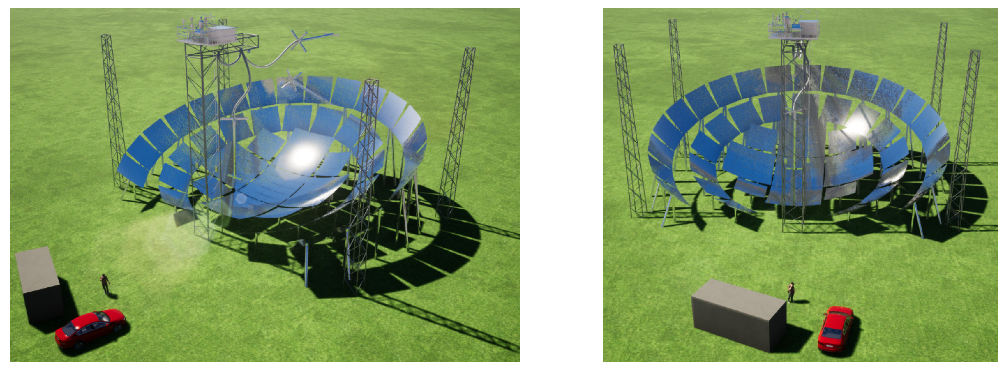
4.4. Modular Plant Configuration

Compared to a central receiver CSP plant, a MOSAIC plant will have more components and more kilometers of piping, which is more similar to a parabolic through the STE plant. This means that more attention needs to be paid to the analysis of losses (thermal and pumping), and that there may be more risks of leakage or freezing if molten salts are used. On the contrary, all modules are built from similar components, so it is possible to replicate the different modules from standardized elements. The tracking towers can also be industrialized and pre-assembled, allowing fast deployment in the field. All this offers enormous cost reduction potential.
In addition, adjacent modules can share the tracking towers. This way, each tower will support the cables of the four adjacent modules, resulting in additional savings.

5. Conclusions

The MOSAIC concept proposes a new SRTA approach for a high-concentration modular plant to produce large scale solar electricity or heat. Compared to other CSP approaches, MOSAIC presents potential advantages (e.g., lower solar field costs, easier maintenance, high efficiencies, cheap energy storage, tailored power capacity) that could lead to more competitive CSP plants.
SRTA systems have demonstrated their applicability for solar heat collection at intermediate and high temperatures, but their large-scale implementation has been poorly studied. Compared to previous SRTA configurations, MOSAIC also addresses the main drawbacks of previous fixed mirror systems. Nevertheless, this new configuration presents uncertainties and challenges that need to be overcome. This article presents the advantages and challenges of this new concept and the measures proposed to overcome them. Some of the most relevant new features of the system are:
  • The semi-Fresnel design of the solar field reduces civil works costs and wind loads, thus addressing the main drawbacks of previous SRTA configurations.
  • The cable-based tracking system that replaces the numerous heliostat drives offers cost reduction potential (CAPEX and OPEX).
  • A modular configuration that allows the development of large, cost-efficient plants, as well as smaller plants for electricity or heat production.
In the coming months, the construction of a large prototype (>300 kWt) will be completed at the CENER facilities (Spain). The results measured and the lessons learned during the implementation and operation of the prototype will make it possible to validate the concept, weigh up the hypotheses and propose improvements for future versions. Consequently, the proposed design for future commercial plants may be redefined.

Author Contributions

Conceptualization, C.V. and M.S.; Methodology, C.V. and M.S.; Validation, S.H. and A.B.; Formal Analysis, D.O.; I.P.; A.P. and S.H.; Investigation, C.V.; S.H.; D.O.; I.P.; A.P.; M.S. and A.B.; Writing-Original Draft Preparation, C.V.; Writing-Review & Editing, S.H. and M.S.; Project Administration, C.V.; Funding Acquisition, C.V. and M.S. All authors have read and agreed to the published version of the manuscript.

Funding

This project has received funding from the European Union’s Horizon 2020 research and innovation program under grant agreement No 727402.

Acknowledgments

We would like to express our sincere gratitude to our colleagues John Harper and Gilles Guigan for their warm welcome at Auroville and their valuable advice.

Conflicts of Interest

“The authors declare no conflict of interest.” “The funders had no role in the design of the study; in the collection, analyses, or interpretation of data; in the writing of the manuscript, or in the decision to publish the results”.

References

  1. McPherson, M.; Mehos, M.; Denholm, P. Leveraging concentrating solar power plant dispatchability: A review of the impacts of global market structures and policy. Energy Policy 2020, 139, 111335. [Google Scholar] [CrossRef]
  2. Crespo, D. STE Can Replace Coal, Nuclear and Early Gas as demonstrated in an Hourly Simulation over 4 Years in the Spanish Electricity Mix. AIP Conf. Proc. 2019, 2126, 130003. [Google Scholar] [CrossRef]
  3. Rashid, K.; Safdarnejad, S.M.; Ellingwood, K.; Powell, M. Techno-economic evaluation of different hybridization schemes for a solar thermal/gas power plant. Energy 2019, 181, 91–106. [Google Scholar] [CrossRef]
  4. Rashid, K.; Mohammadi, K.; Powell, K. Dynamic simulation and techno-economic analysis of a concentrated solar power (CSP) plant hybridized with both thermal energy storage and natural gas. J. Clean. Prod. 2020, 248, 119193. [Google Scholar] [CrossRef]
  5. Rovense, F.; Reyes-Belmonte, M.A.; Gonzalez-Aguilar, J.; Amelio, M.; Bova, S.; Romero, M. Application of un-fired closed Brayton cycle with mass flow regulation and particles based thermal energy storage systems for CSP. AIP Conf. Proc. 2019, 2126, 030047. [Google Scholar] [CrossRef]
  6. Bhargava, K.R.; Grossb, F.; Schramek, P. Life Cycle cost optimized heliostat size for power towers. Energy Proc. 2014, 49, 40–49. [Google Scholar] [CrossRef] [Green Version]
  7. Villasante, C.; Pagola, I.; Pena, A.; Sanchez, M.; Olarra, A.; Gomez-Acedo, E.; Herrero, S. MOSAIC, a new CSP plant concept for the highest concentration ratios at the lowest cost. AIP Conf. Proc. 2019, 2126, 060008. [Google Scholar] [CrossRef]
  8. Steward, W.G.; Kreith, F. Stationary concentrating reflector/tracking absorber solar energy collector: Optical design characteristics. Appl. Opt. 1975, 14, 1509–1512. [Google Scholar] [CrossRef] [PubMed]
  9. Dirks, J.A.; Williams, T.A.; Brown, D.R. Performance and Cost Implications of the Fixed Mirror, Distributed Focus (FMDF) Collector. J. Sol. Energy Eng. 1992, 114, 254–259. [Google Scholar] [CrossRef]
  10. Goodman, J.H. Solar Concentrating Architectonics; Solar Bowl Architectonics and Interior Heliostats Architectonics; c/o HANDance Designs: Walton: Spring Green, WI, USA, 1993. [Google Scholar]
  11. Adams, W. Solar Heat-A Substitute for Fuel in Tropical Countries for Heating Steam Boilers and Other Purposes; NYC Public Library; N.U.C. #NA 0065154; Education Society’s Press: Byculla, Bombay, India, 1878; p. 112. [Google Scholar]
  12. Cohen, S.; Grossman, G. Development of a solar collector with a stationary spherical reflector/tracking absorber for industrial process heat. Sol. Energy 2016, 128, 31–40. [Google Scholar] [CrossRef]
  13. Berland, J.J.G. Machine Solaire à Air Atmosphérique. French Patent No. FR635283 (A), 3 Decembar 1928. [Google Scholar]
  14. Kreider, J.F. Thermal performance analysis of the stationary reflector/tracking absorber (SRTA) solar concentrator. ASME J. Heat Transf. 1975, 97, 451–456. [Google Scholar] [CrossRef]
  15. Guigan, G.; Harper, J. Auroville Solar Bowl Concentrator for Community Scale Steam Cooking. Report of the Project Funded by the Government of India, May 2008. Available online: https://research.auroville.org/system/papers/attachments/000/000/623/original/Auroville_Solar_Bowl_Concentrator_for_the_Communit..Cooking_Auroshilpam_2008.pdf (accessed on 30 January 2020).
  16. O’Hair, E.A.; Simpson, T.L.; Green, B. Results from Operation of the Crosbyton Solar Bowl. In Proceedings of the 8th ASME Solar Energy Division Conference, Anaheim, CA, USA; Ferber, R.R., Ed.; American Society of Mechanical Engineers: New York, NY, USA, 1986; pp. 205–209. [Google Scholar]
  17. Authier, B. Capteur D’energie Solaire a Miroir Spherique Fixe. French Patent No. FR2365085 (A1), 14 April 1978. [Google Scholar]
  18. Grossman, G.; Fruchter, E.; Kreith, F. An experimental investigation of a stationary reflector/tracking absorber solar collector at intermediate temperatures. J. Sol. Energy Eng. 1982, 104, 340–344. [Google Scholar]
  19. Experimental Set-up for a SRTA at Technion-Israel Institute of Technology. Available online: https://www.youtube.com/watch?v=WBb7hDGUSng&t=182s (accessed on 1 April 2020).
  20. Harper, J. Construction of a Stationary Spherical Reflector for Rural Use; Final report of the project sponsored by Tata Energy Research Institute; Tata Energy Research Institute: Auroville, Tamil Nadu, India, 1982. [Google Scholar]
  21. Kenna, J. Construction and Testing of a Pilot Solar thermal power station using an innovative mirror concept. Report for JOR3CT960046 project (1996–1999) funded under FP4-NNE-JOULE C Program. Available online: http://cordis.europa.eu/publication/rcn/1452_en.html (accessed on 30 January 2020).
  22. Larbi, A.B. A new design of a (3D) Fresnel collector with fixed mirrors and tracking absorber. J. Sol. Energy Eng. 2000, 122, 63–68. [Google Scholar] [CrossRef]
  23. Sanchez, M. Potential of Optimized Non-Tracking Mirror Concentrators for Distributed Solar Applications. In Proceedings of the SolarPACES Conferences, Oaxaca, Mexico, October 2004. [Google Scholar]
  24. Hariharan, S. Simulation of the receiver in a fixed-mirror distributed focus solar power system. Ph.D. Thesis, Texas Tech University, Lubbock, TX, USA, August 1981. [Google Scholar]
  25. Kortaberria, G.; Gomez-Acedo, E.; Molina, J.; Tellaeche, A.; Minguez, R. Theoretical accuracy assessment of model-based photogrammetric approach for pose estimation of cylindrical elements. Meas. Sci. Technol. 2019, 30, 1–17. [Google Scholar] [CrossRef] [Green Version]
  26. Steward, W.G. Receiver for solar energy. US Patent No. U.S.4173968 (A), 13 November 1979. [Google Scholar]
  27. Zanino, R.; Cagnoli, M.; Falsig, J.J.; Pagola, I.; Peña, A.; Savoldi, L.; Villasante, C. Design and Analysis of the Helical Receiver for the MOSAIC Prototype Solar Bowl System. J. Sol. Energy. under review.
Figure 1. Spherical concentrators characteristics: (a) case of rays perpendicular to the aperture; (b) cases of rays not perpendicular to the aperture and its effect on reducing the effective aperture area.
Energies 13 01816 g001
Figure 2. Stationary reflector/tracking absorber (SRTAs) incorporated in building roofs: (a) Steward residence with 9.14 m diameter bowl at Boulder, Colorado. The design began in 1968 [10]; (b) Solar bowl integrated into the roof of the community kitchen in Auroville Universal Township, Tamil Nadu, India [15]; (c) An industrial building concept with the roof constructed of SRTA modules as proposed by Cohen et al. [12].
Energies 13 01816 g002
Figure 3. The Fresnel approach for spherical concentrators [23]. (a) Raytracing for concentric spheres; (b) Model built by Sánchez in the early 2000s to prove the Fresnel concept.
Energies 13 01816 g003
Figure 4. 3D view of a MOSAIC module.
Energies 13 01816 g004
Figure 5. Definition of the solar field for a MOSAIC module: (a) Schematic cross-section showing a central bowl and three rings beside a cylindrical receiver; (b) Annual contribution for a given configuration and tilt angle. The southern mirrors contributing less have been removed.
Energies 13 01816 g005
Figure 6. Small facets glued to the spherical concrete bowl in Auroville, India [15]: (a) Gluing and canting process; (b) Mirrors seen from the center of the sphere.
Energies 13 01816 g006
Figure 7. Solar field configuration to be implemented in the prototype. The outer rings are composed of 9-mirror modules (3 × 3), while the central bowl includes 25-mirror modules (5 × 5) and 9-mirror modules (3 × 3): (a) Top view; (b) Front view.
Energies 13 01816 g007
Figure 8. Tripod-type structures supporting the tracking system, (a) the design for the system in Crosbyton as described in [24]; (b) Installation in Crete that included a tripod and an additional structure rolling over the spherical surface.
Energies 13 01816 g008
Figure 9. Proposed solution and previous approaches combining tripod-type structures and cable traction: (a) solar heat production system proposed by Cohen [12]; (b) system patented by Authier [17]; (c) sketch of the proposed solution.
Energies 13 01816 g009
Figure 10. Proposed tracking configuration: (a) Receiver at noon positions for two different seasons; (b) schematic representation of the cables that hold and move the receiver.
Energies 13 01816 g010
Figure 11. Receivers made of spiral tubes: (a) Design implemented in Auroville, India [15]; (b) design proposed by Authier [17] including a pre-heater (3a) and a high concentration heater on top (3b); (c) receiver patented by Steward [26], including a transparent envelope (24).
Energies 13 01816 g011
Figure 12. Different configurations analyzed: (a) Annular configuration; (b) tubes placed according to the generating lines of a cylinder; (c) coil type configuration.
Energies 13 01816 g012
Figure 13. Receiver design: (a) Main dimensions; (b) 3D view.
Energies 13 01816 g013
Table 1. The largest SRTA prototypes to date.
SiteCrosbyton, TX, USAMarseilles, France
Recife, Brazil
Haifa, IsraelAuroville, IndiaCrete, Greece
Photo Energies 13 01816 i001 Energies 13 01816 i002 Energies 13 01816 i003 Energies 13 01816 i004 Energies 13 01816 i005
Date1970s1970s1970s1990s1990s
Size19.7 m aperture diameter10 m aperture diameter10 m aperture diameter15 m aperture diameter30 m curvature
HTF/ tempSteam at 538 °CGilotherm TH oil at 330 °CSteam at 300 °CLow pressure SteamAir at 850 °C
StatusDecommissionedDecommissionedDecommissionedStill in operationDecommissioned
Table 2. Analysis of possible SRTA configurations and their effect on the annual contribution of each area [23]. The annual contribution graphs represent the kWh/m2 provided by each mirror seen from the center of the spheres (aperture plane).
‘Actual Sphere’‘Flat Fresnel’‘Semi-Fresnel’
Configuration Energies 13 01816 i006 Energies 13 01816 i007 Energies 13 01816 i008
Annual contribution Energies 13 01816 i009 Energies 13 01816 i010 Energies 13 01816 i011

