Article

Magnetizing Characteristics of Bridge Type Superconducting Fault Current Limiter (SFCL) with Simultaneous Quench Using Flux-Coupling

1
Industry-University Cooperation Foundation, Kongju National University, Chungnam 32586, Korea
2
Department of Aero Materials Engineering, Jungwon University, Chungbuk 28024, Korea
3
Department of Electrical Engineering, Soongsil University, 369, Sangdo-ro, Dongjak-gu, Seoul 06978, Korea
*
Author to whom correspondence should be addressed.
Energies 2020, 13(7), 1760; https://doi.org/10.3390/en13071760
Submission received: 20 February 2020 / Revised: 4 April 2020 / Accepted: 5 April 2020 / Published: 7 April 2020
(This article belongs to the Section A1: Smart Grids and Microgrids)

Abstract

:
A bridge type superconducting fault current limiter (SFCL) with simultaneous quench using two high-temperature superconducting (HTSC) elements and two coils was fabricated to analyze the fault current limiting characteristics. Before and after the fault occurrence, the current limiting operation and the voltage waveforms of each device were compared according to the change of the input voltage. We also analyzed flux linkages and instantaneous powers of the bridge type SFCL with simultaneous quench using flux-coupling composed of HTSC elements with different critical currents. During the fault period, the magnetization power area and the flux linkage’s operating range variation due to the magnetizing current were compared with each other.

1. Introduction

Superconducting fault current limiters (SFCLs) are fundamental components of modern electrical systems at both medium and high voltages. Many research efforts have been carried out to reduce fault currents in alternating current (AC) or direct current (DC) systems [1,2,3,4,5,6,7]. Among other SFCLs, bridge type SFCL using reactors do not require quenching and can significantly reduce AC losses. This bridge type SFCL is generally composed of a diode or thyristor and a superconducting coil, and has the disadvantage of being larger than other types of SFCL due to the superconducting coil. In addition, this SFCL is expensive and requires controllers and circuit breakers to protect the superconducting coils from accidents [8,9,10,11]. In order to overcome this drawback, DC double reactor type SFCL using switching operation of a high-temperature superconducting (HTSC) device has been proposed and fault current limiting characteristics have been reported [12]. However, this DC double reactor type SFCL has not been investigated for the magnetization characteristics and instantaneous power burden characteristics according to the input voltage change at the time of failure. In this paper, we proposed a bridge type SFCL with sim ultaneous quench using flux-coupling as a preliminary step of DC system. The fault current limiting operation, voltage waveforms, instantaneous power and magnetic flux, and magnetization of each device are analyzed for this bridge type SFCL. When the input AC voltage source was changed, we tried to analyze the range of voltage induced by the magnetizing current, the change of energy consumption, the range of the magnetization power, and the operating range of the magnetic flux linkage. A lab scale prototype was built and failure short-circuit experiment was performed. We tried to verify its usefulness by analyzing fault current limiting operation and magnetization characteristics of bridge type SFCL with simultaneous quench.

2. Structure and Operating Principle

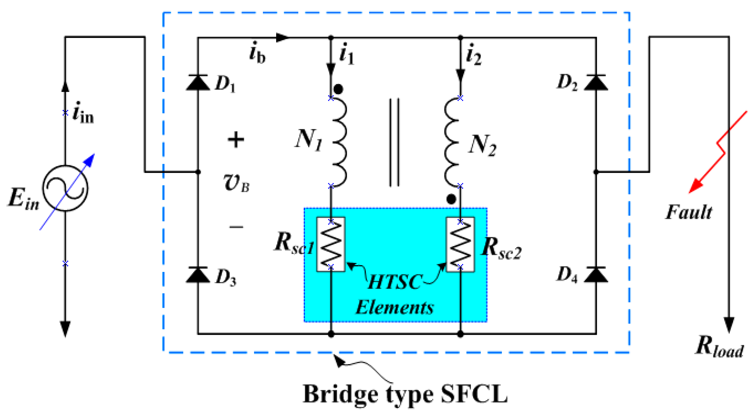
2.1. Sturcture and Principle

Figure 1 shows the structure of a bridge type SFCL with simultaneous quench using flux-coupling. This bridge type SFCL consists of one iron core, two windings, two high-temperature superconducting (HTSC) elements and four diodes. The wiring direction between the primary and secondary windings (N1, N2) is an additive polarity winding and is connected in parallel with each other. In addition, the AC power supply voltage (Ein) is designed to be variable. The DC section is a full-wave bridge circuit consisting of four diodes. The HTSC elements were Y1Ba2Cu3O7-x (YBCO) thin films deposited with a 200 nm thick platinum layer and used a product of Theva, with a critical temperature of 87 K.
As a basic principle of operation, under conditions before failure occurs, the resistance of the HTSC elements becomes zero because no quench occurs. In addition, because the current flowing through the windings N1 and N2 is DC, these two coils are bypassed and no magnetic flux occurs. Eventually, the impedance of this SFCL becomes zero. However, after a fault has occurred, the transient fault currents exceed the critical currents of the HTSC elements connected in series with the N1 and N2 windings, causing resistance in the HTSC elements and quenching them. The DC current flowing through the N1 and N2 windings is mixed with the AC ripple component to generate magnetic flux. As a result, the non-inductive coupling breaks, limiting the fault current.

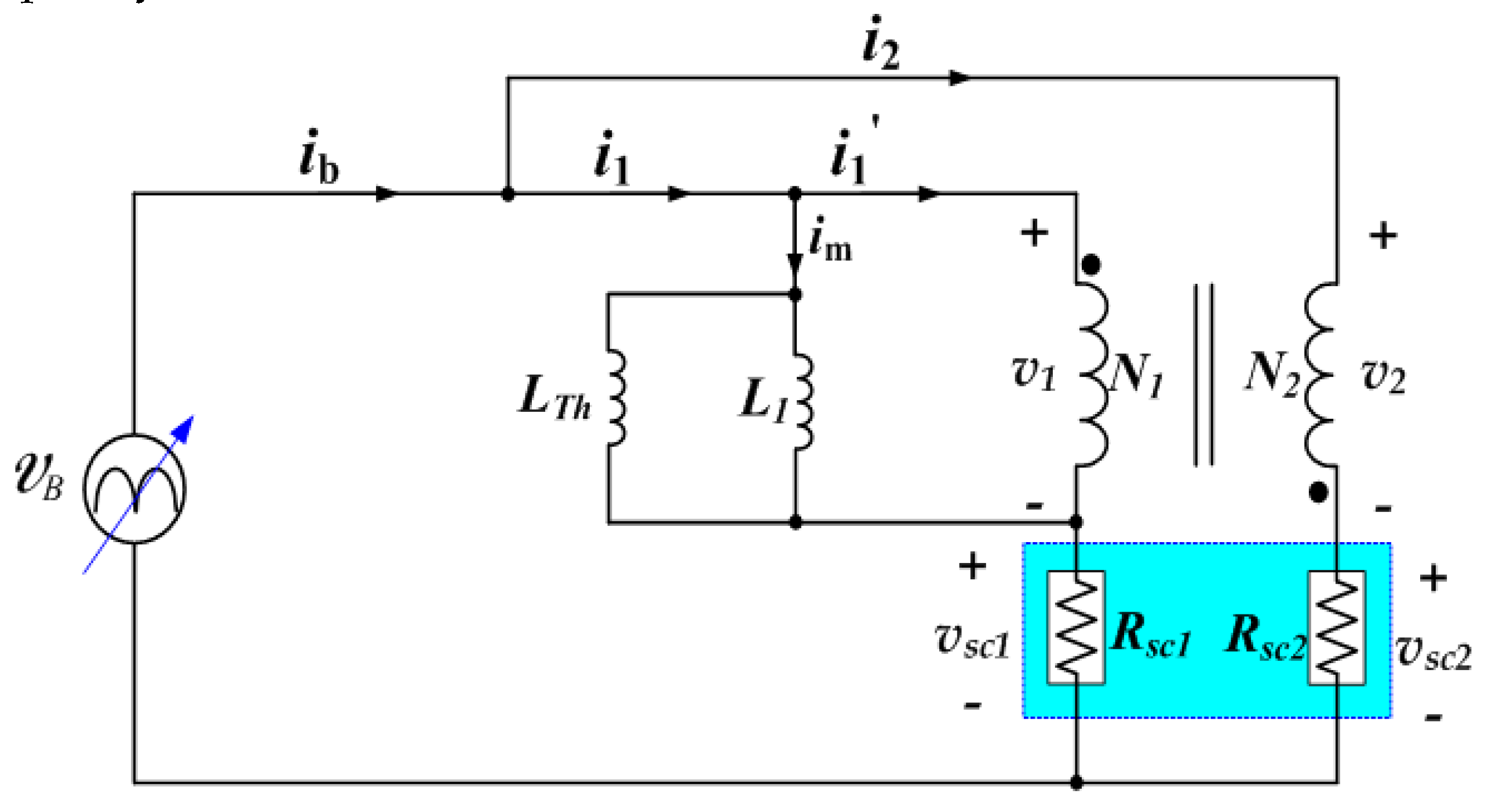
2.2. Equivalent Circuit

Figure 2 shows the electrical equivalent circuit of a bridge type SFCL with simultaneous quench using flux-coupling. This equivalent circuit can be derived from the magnetic equivalent circuit using the topology principle of duality [13]. The resistance and leakage inductance of each winding is omitted for simplicity. L1 and LTh represent the self-inductance wound on the core and the equivalent inductance for both windings, respectively. In the case of the additive polarity winding between the N1 and N2 windings, the magnetizing current ( i m ) and the limiting impedance (ZSFCL) of the bridge type SFCL with simultaneous quench using flux-coupling can be expressed by Equations (1) and (2).
i m = i 1 i 1 = i 1 + N 2 N 1 i 2
Here, i 1 and i 2 denote instantaneous values of currents flowing through the primary and secondary windings, respectively.
Z S F C L = 1 [ 1 V 1 ( N 2 N 1 V s c 2 R s c 2 ) + 1 j ω L e q ] + R s c 1
Here, V1 and VSC2 expressed in phasor form represent voltages induced by the primary winding and the HTSC element 2, respectively. N1 and N2 represent the number of turns of each winding, and Leq is equal to LTh//L1. RSC1 and RSC2 represent the resistances of two HTSC elements, respectively, and ω is angular frequency.

3. Experimental Results

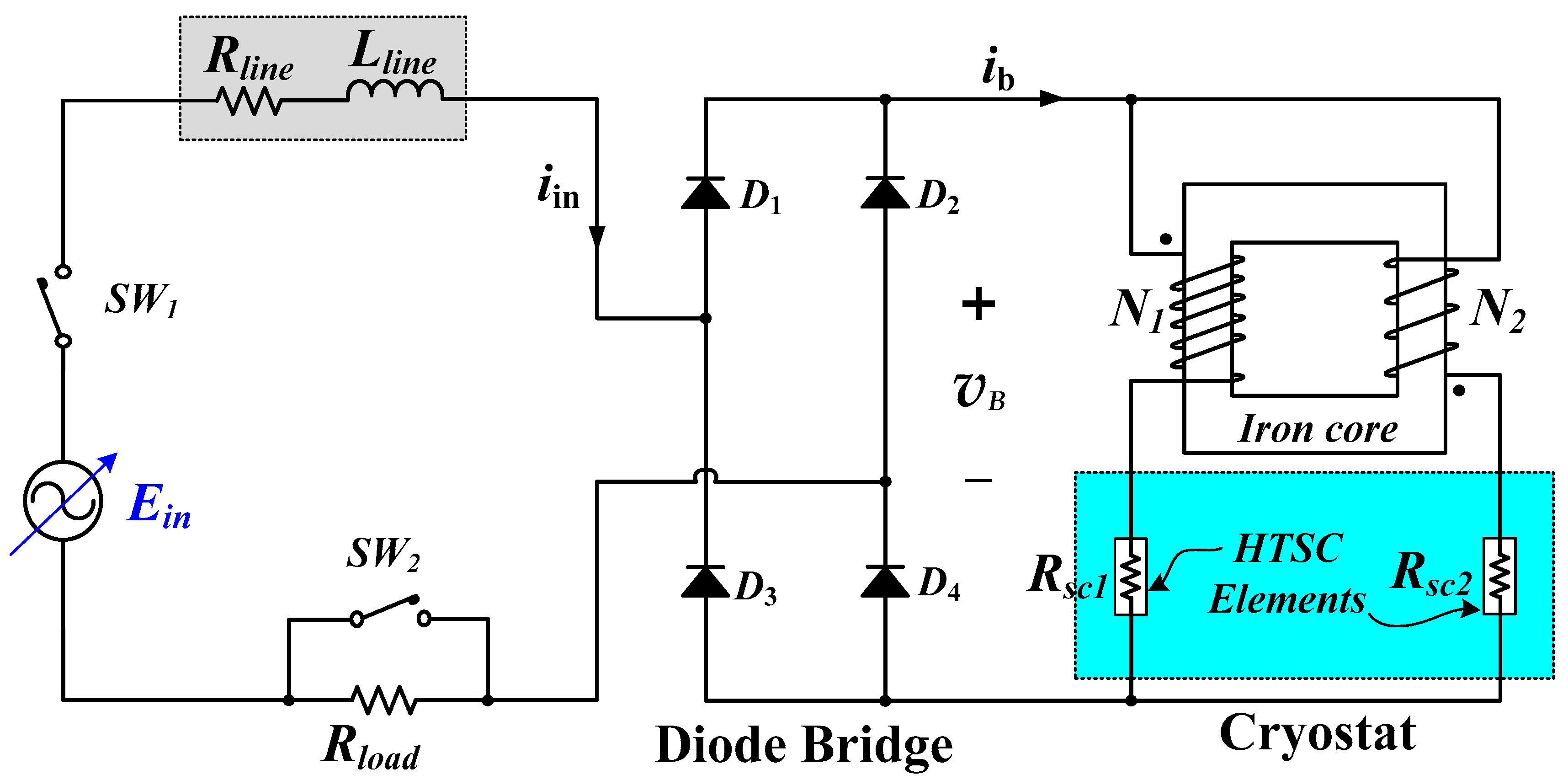
3.1. Preparation of Experiment

Table 1 shows the design parameters of a bridge type SFCL with simultaneous quench using flux-coupling. The critical currents (Ic1, Ic2) of HTSC elements 1 and 2 were used by patterning YBCO thin films with 18.15 and 19.04 A, respectively. The fabrication process of the HTSC elements used in this experiment is described in detail in [14].
Figure 3 shows the experimental setup for simulating the various characteristics of bridge type SFCL with simultaneous quench using flux-coupling when the input voltage is changed differently. The fault test was performed at 80 Vrms and 100 Vrms AC input voltage (Ein) at 60 Hz and fault angle 0 °. The test equipment consisted of a full-wave bridge for DC, a line reactance of 1.59 mH (Lline), a line resistance of 1 Ω (Rline), a load resistance of 50 Ω (Rload), two windings on one iron core, two HTSC elements. After SW1 is closed, SW2 is designed to close at the fault angle 0 ° of the AC power supply and reopen after the fault period.

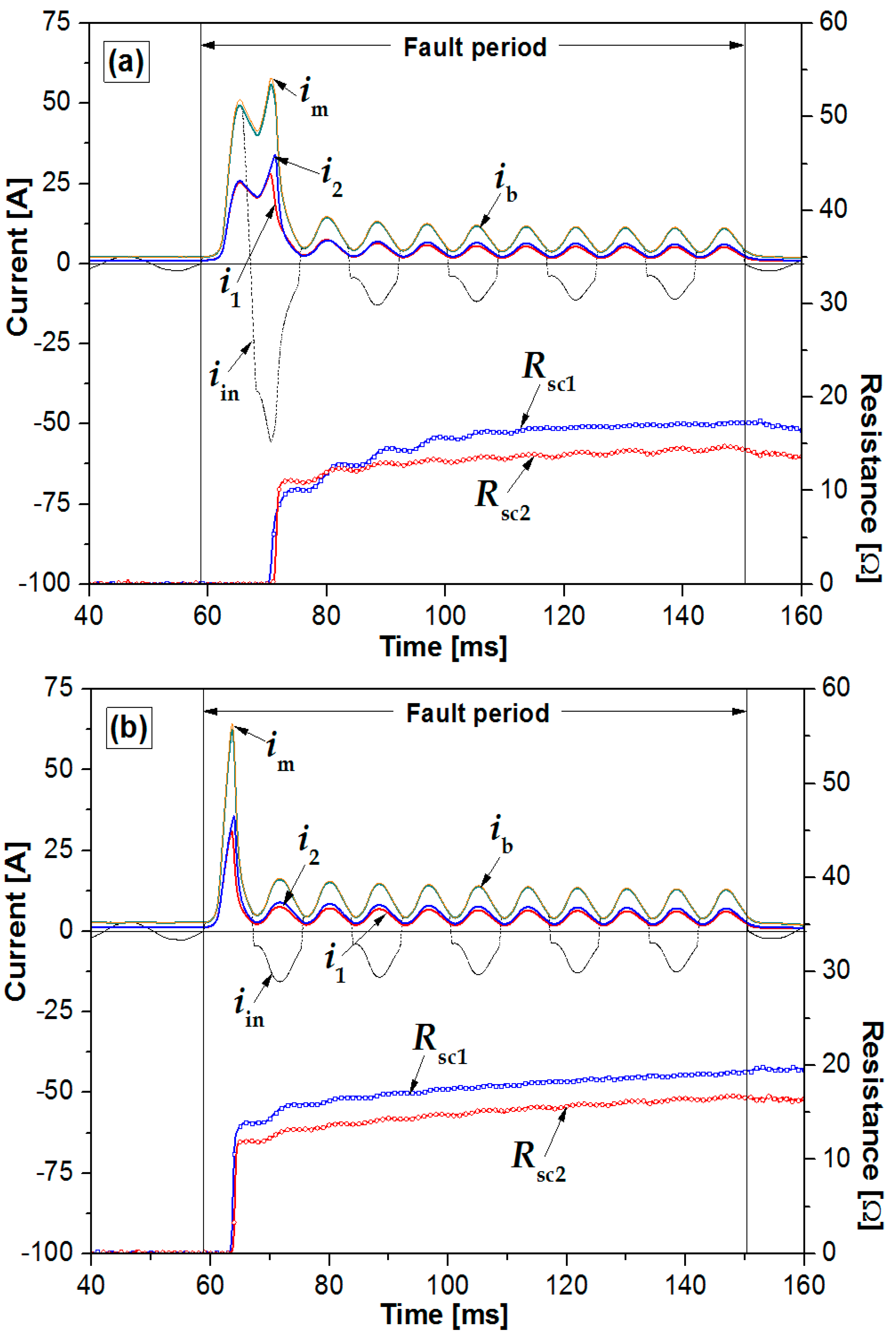
3.2. Experimental Results

Figure 4a,b show the fault current limiting characteristics of the bridge type SFCL when the input voltage source is changed from 80 Vrms to 100 Vrms, respectively. When the input voltage source was 100 Vrms as shown in Figure 4b, the fault current and the magnetizing current increased much faster after a fault, and the HTSC elements 1 and 2 were quenched at about the same time in half cycle. It can be seen that the quench occurs first and the fault current is limited when the input voltage source is 100 Vrms (See Figure 4b) rather than 80 Vrms (See Figure 4a).
Figure 5a,b show the voltage waveforms of each winding and HTSC element when the input voltage source is changed from 80 Vrms to 100 Vrms, respectively. When the input voltage source was 100 Vrms as shown in Figure 5b, the voltage waveforms of the HTSC elements, the full-wave bridge voltage waveform of the rectifier stage, and the voltage waveforms of two windings increased. However, as shown in Figure 5a,b it can be seen that the voltage ( v 2 ) across N2 is minutely generated before the quench occurs due to the leakage current of the winding.
Figure 6 shows the magnetic flux of each winding and instantaneous power burden of each device as the input voltage source changes to 80 Vrms and 100 Vrms, respectively, during the fault period. As the input voltage source was increased, the magnetic flux (ϕ1) of the primary winding hardly changed, but the magnetic flux (ϕ2) of the secondary winding decreased significantly. On the other hand, it can be observed that the instantaneous power consumed by the primary and secondary windings and the HTSC elements 1 and 2 are much larger when the input voltage source is increased immediately after the failure.
Figure 7 shows the characteristics of the energy dissipated by the magnetization power and the range of fluctuation in the voltage induced in each winding for the magnetizing current during the fault cycle when the input voltage source changes to 80 Vrms and 100 Vrms, respectively. Figure 7 shows the x-axis as the magnetizing current ( i m ) and the y-axis as the voltage ( v 1 and v 2 ) across both windings during the fault period. Moreover, the energy ( J m ) consumed by the magnetization power can be obtained by integrating the product of the time (t) and the magnetization power ( p m ) during the fault period. Therefore, the relationship curve between the voltage of each winding and the energy consumed by the magnetizing current can be obtained as shown in Figure 7. When the input voltage source increases during the fault cycle, the range of voltage induced in the primary winding is large, but the range of voltage induced in the secondary winding appears small and converges to nearly zero. In addition, it can be seen that during the fault period, the energy dissipated by the magnetization power increases with the increase and decrease of the magnetizing current and then decreases to converge to the magnetizing current 10 A point. It can be observed that as the input voltage source increases, the range of increase and decrease of magnetizing current is wide, but energy consumption is low.
Figure 8 shows the operating range of the magnetization power ( p m ) and the magnetic flux linkage (λ) according to the magnetizing current during the fault period when the input voltage source changes to 80 Vrms and 100 Vrms, respectively. Referring to the equivalent circuit in Figure 2, flux linkages (λ1, λ2) of the primary and secondary windings and magnetization power ( p m ) can be redrawn on the axis by the magnetizing current as shown in Figure 8. During the fault period, flux linkages 1 and 2 can be calculated as λ 1 = v 1 d t , λ 2 = v 2 d t , and the magnetization power can be obtained by calculating p m = v 1 i m . Therefore, as shown in Figure 8, it is possible to obtain a relationship curve between magnetization power and flux linkage according to the magnetizing current. As the input voltage source increases, the maximum magnetization power is 0.17 kW higher, and it can be seen that the change of the magnetization power area according to the magnetizing current is much larger. As the magnetizing current increases and decreases, the operating range of the flux linkages 1 and 2 gradually increases and then decreases again, showing that the magnetization current converges at about 10 A. When the input voltage source was increased from 80 Vrms to 100 Vrms, the maximum flux linkage of λ1 and λ2 during the fault period differed by less than 0.02 and 0.09 Wb, respectively. However, it can be seen that the operating range of λ1 and λ2 is slightly larger when the input voltage source is changed to 100 Vrms.

4. Conclusions

In this paper, we compared and analyzed the energy consumption change, magnetization power area change, and flux linkage operating range due to magnetizing current when the turns ratio of N1 and N2 were kept 1:1 and the input voltage source was changed from 80 Vrms to 100 Vrms, respectively. Immediately after the fault, the fault current and magnetizing current increased even more rapidly, and it was observed that HTSC elements 1 and 2 were simultaneously quenched in half cycle. When the turns ratio of N1 and N2 are the same and the input voltage source is increased from 80 Vrms to 100 Vrms, the following conclusions can be drawn.
(1)
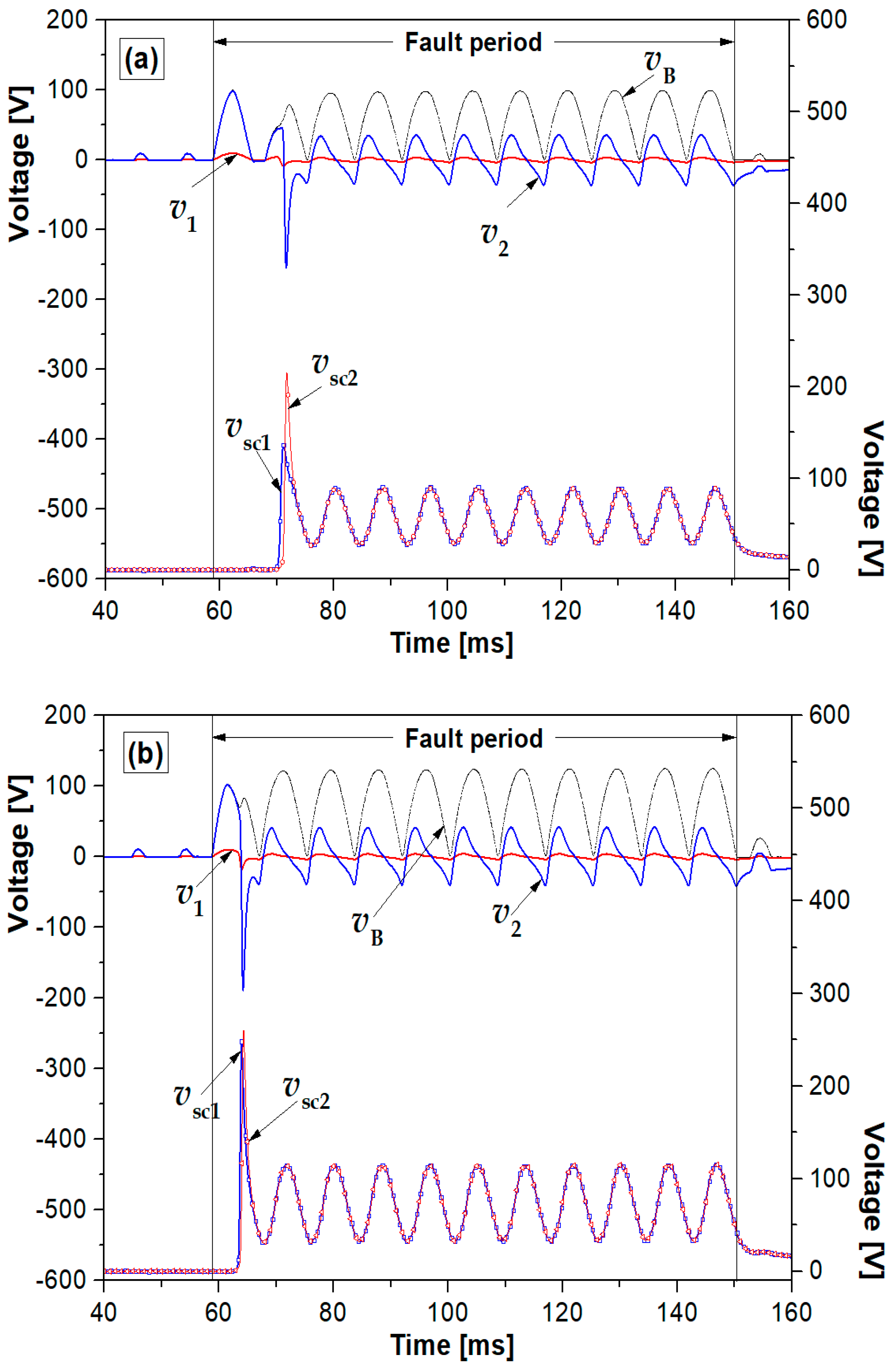
The fault current can be limited faster.
(2)
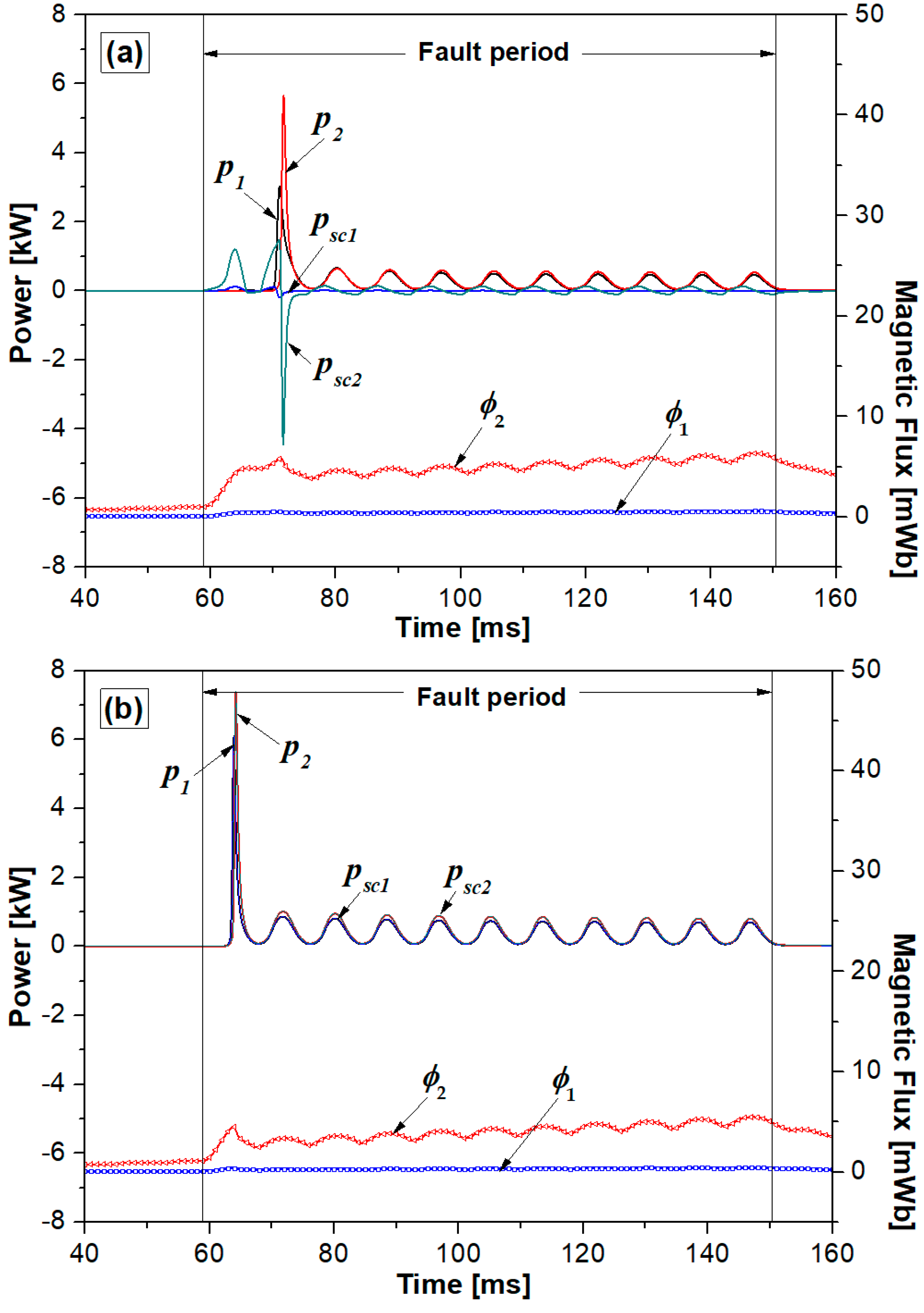
The magnetic flux (ϕ1) of the primary winding had little change, but the magnetic flux (ϕ2) of the secondary winding decreased significantly.
(3)
Immediately after the failure, the power consumption of HTSC elements acted more.
(4)
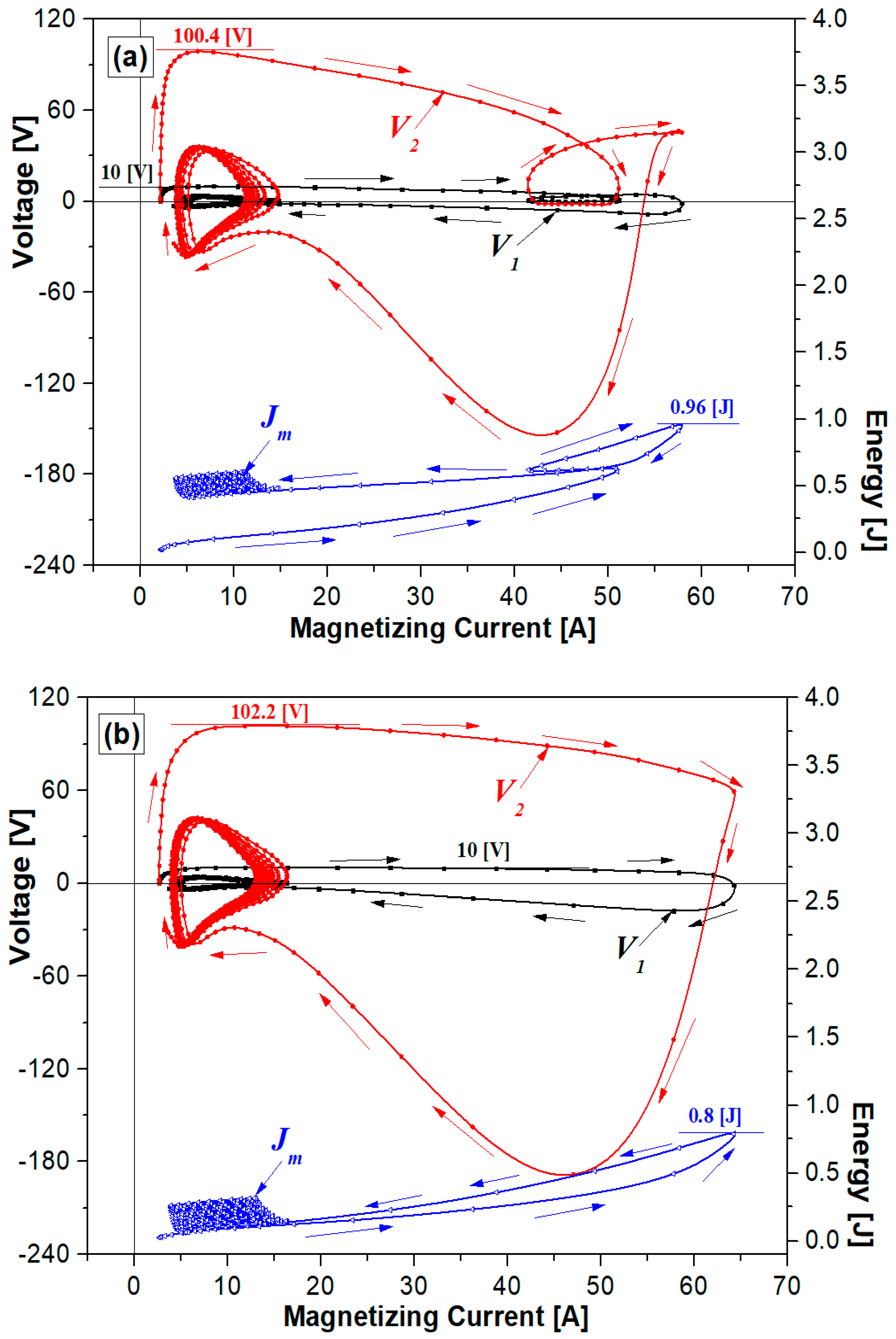
During the fault period, the range of voltage fluctuation according to the magnetizing current was wider, but the energy ( J m ) consumed by the magnetization power was small.
(5)
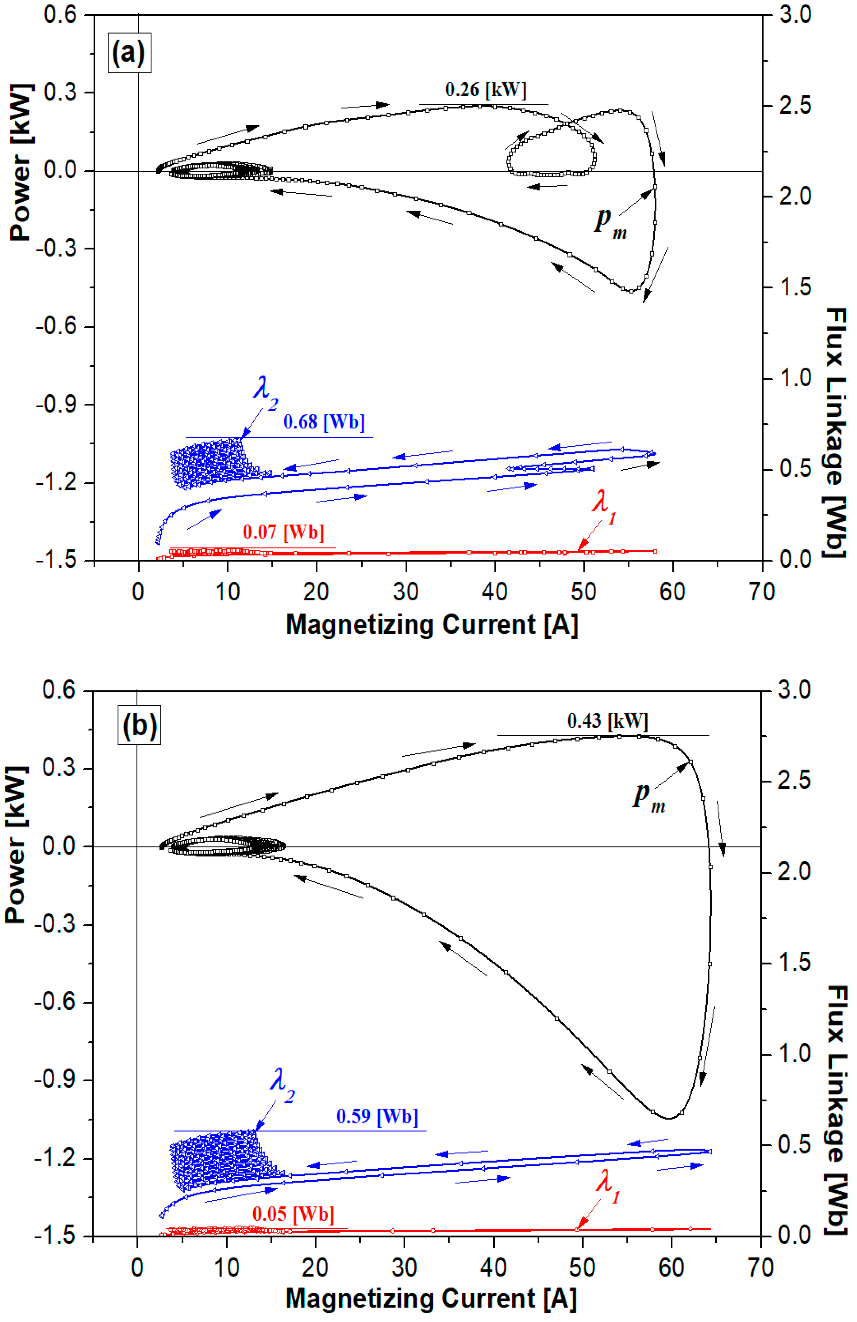
During the fault period, both the maximum magnetization power and the magnetization power’s area change were high according to the magnetizing current.
(6)
The maximum flux linkages (λ1, λ2) of the primary and secondary windings during the fault period were small, but their operating range was slightly wider.
In conclusion, the larger the input voltage source, the faster the fault current can be limited, and has the advantage of increasing the maximum magnetization power and the change in the area of magnetization power according to the magnetizing current. However, HTSC elements have a disadvantage in that power consumption is greater and flux linkages have a wider operating range.

Author Contributions

Writing-original draft, S.-C.K.; Designed the experiments and analyzed the experimental data, T.-H.H.; Writing-review and editing, S.-H.L. All authors have read and agreed to the published version of the manuscript.

Funding

This research was funded by Basic Science Research Program through the National Research Foundation of Korea (NRF) funded by the Ministry of education (2018R1D1A1B07040471) and funded by the Ministry of education (2018R1D1A1B09083558). This research was also supported by Korea Electric Power Corporation. (Grant number: R19XO01-19).

Conflicts of Interest

The authors declare no conflict of interest.

Nomenclature

HTSCthe high temperature superconducting
Einthe AC power supply voltage
iinthe input current of the bridge type SFCL
ibthe total current of the primary winding and the secondary winding
i1the current of the primary winding
i2the current of the secondary winding
imthe magnetizing current
N1the turn number of the primary winding
N2the turn number the secondary winding
L1the self-inductance wound on the core
LThthe equivalent inductance for both windings
ZSFCLthe limiting impedance
v B the voltage rectified by the full-wave bridge
v 1 the voltage induced by the primary winding
v 2 the voltage induced by the secondary winding
v s c 1 the voltage induced by the HTSC element 1
v s c 2 the voltage induced by the HTSC element 2
RSC1the resistance of HTSC element 1
RSC2the resistance of HTSC element 2
Ic1the critical current of HTSC element 1
Ic2the critical current of HTSC element 2
Llinethe line inductance
Rlinethe line resistance
Rloadthe load resistance
Vrmsthe input voltage source
ϕ1the magnetic flux of the primary winding
ϕ2the magnetic flux of the secondary winding
P1the power of the primary winding
P2the power of the secondary winding
PSC1the power of HTSC element 1
PSC2the power of HTSC element 2
pmthe magnetization power
Jmthe joule energy dissipated by the magnetization power
λthe flux linkage
λ1the flux linkage of the primary winding
λ2the flux linkage of the secondary winding

References

  1. Hara, T.; Okuma, T.; Yamamoto, T.; Ito, D.; Tasaki, K.; Tsurunaga, K. Development of a new 6.6 kV/1500 A class superconducting fault current limiter for electric power systems. IEEE Trans. Power Deliv. 1993, 8, 182–192. [Google Scholar] [CrossRef]
  2. Kadoe, H.; Ichikawa, M. Performance of a high-Tc superconducting fault current limiter-design of a 6.6 kV magnetic shielding type superconducting fault current limiter. IEEE Trans. Appl. Supercon. 1997, 7, 993–996. [Google Scholar] [CrossRef]
  3. Yamaguchi, H.; Kataoka, T.; Yaguchi, K.; Fujita, S.; Yoshikawa, K.; Kaiho, K. Characteristics analysis of transformer type superconducting fault current limiter. IEEE Trans. Appl. Supercon. 2004, 14, 815–818. [Google Scholar] [CrossRef]
  4. Lee, G.H.; Park, K.B.; Sim, J.; Kim, Y.G.; Oh, I.S.; Hyun, O.B.; Lee, B.W. Hybrid superconducting fault current limiter of the first half cycle non-limiting type. IEEE Trans. Appl. Supercond. 2009, 19, 1888–1891. [Google Scholar]
  5. Liang, S.; Tang, Y.; Xia, Z.; Ren, L.; Chen, L.; Xu, Y.; Wang, Z.; Yan, S. Study on the current limiting performance of a novel SFCL in DC systems. IEEE Trans. Appl. Supercond. 2017, 27, 5601106. [Google Scholar] [CrossRef]
  6. Ko, S.C.; Lim, S.H. Analysis on magnetizing characteristics due to peak fault current limiting operation of a modified flux-lock-type SFCL with two magnetic paths. IEEE Trans. Appl. Supercond. 2016, 26, 5601605. [Google Scholar] [CrossRef]
  7. Lee, H.Y.; Asif, M.; Park, K.H.; Lee, B.W. Feasible application study of several types of superconducting fault current limiters in HVDC grids. IEEE Trans. Appl. Supercond. 2018, 28, 5601205. [Google Scholar] [CrossRef]
  8. Lee, S.; Kang, H.; Bae, D.K.; Ahn, M.C.; Mun, T.; Park, K.; Lee, Y.; Ko, T.K. Development of 6.6 kV-200 A DC reactor type superconducting fault current limiter. IEEE Trans. Appl. Supercond. 2004, 14, 867–870. [Google Scholar] [CrossRef]
  9. Morandi, A.; Imparato, S.; Grasso, G.; Berta, S.; Martini, L.; Bocchi, M.; Fabbri, M.; Negrini, F.; Ribani, P.L. Design of a DC resistive SFCL for application to the 20 kV distribution system. IEEE Trans. Appl. Supercond. 2010, 20, 1122–1126. [Google Scholar] [CrossRef]
  10. Jiang, L.; Jin, J.X.; Chen, X.Y. Fully controlled hybrid bridge type superconducting fault current limiter. IEEE Trans. Appl. Supercond. 2014, 24, 5602705. [Google Scholar]
  11. You, H.; Jin, J. Characteristic analysis of a fully controlled bridge type superconducting fault current limiter. IEEE Trans. Appl. Supercond. 2016, 26, 5603706. [Google Scholar] [CrossRef]
  12. Lim, S.H.; Choi, H.S.; Han, B.S. Fault current limiting characteristics of DC dual reactor Type SFCL using switching operation of HTSC elements. IEEE Trans. Appl. Supercond. 2006, 16, 723–726. [Google Scholar] [CrossRef]
  13. Joo, M.S.; Ko, T.K. Novel design and operational characteristics of inductive high-Tc superconducting fault current limiter. IEEE Trans. Appl. Supercond. 1997, 7, 1005–1008. [Google Scholar]
  14. Kim, H.R.; Choi, H.S.; Lim, H.R.; Kim, I.S.; Hyun, O.B. Initial quench development in uniform Au/Y-Ba-Cu-O thin films. IEEE Trans. Appl. Supercond. 2001, 11, 2414–2417. [Google Scholar]
Figure 1. Schematic configuration of bridge type superconducting fault current limiter (SFCL) with simultaneous quench using flux-coupling.
Energies 13 01760 g001
Figure 2. Electrical equivalent circuit of bridge type SFCL with simultaneous quench using flux-coupling according to the input voltage variation.
Energies 13 01760 g002
Figure 3. Schematic diagram for the experimental circuit of bridge type SFCL with simultaneous quench according to the input voltage variation.
Energies 13 01760 g003
Figure 4. Fault current limiting operating characteristics of bridge type SFCL using flux-coupling according to the change of input voltage source. (a) E i n = 80   V r m s . (b) E i n = 100   V r m s .
Energies 13 01760 g004
Figure 5. Voltage waveforms of full bridge circuit, each winding and HTSC elements ( v B , v 1 , v 2 and v S C 1 , v S C 2 ) according to the change of input voltage source. (a) E i n = 80   V r m s . (b) E i n = 100   V r m s .
Energies 13 01760 g005
Figure 6. Instantaneous powers and magnetic flux in each winding of bridge type SFCL using flux-coupling according to the change of input voltage source. (a) E i n = 80   V r m s . (b) E i n = 100   V r m s .
Energies 13 01760 g006
Figure 7. Variation of induced voltage and consumed energy of each winding due to magnetizing current ( i m ) during fault period in the bridge type SFCL using flux-coupling according to the change of input voltage source. (a) E i n = 80   V r m s . (b) E i n = 100   V r m s .
Energies 13 01760 g007
Figure 8. Variation of magnetization power ( p m ) area and flux linkage’s (λ) operational range dependent on the magnetizing current ( i m ) during fault period in the bridge type SFCL using flux-coupling according to the change of input voltage source. (a) E i n = 80   V r m s . (b) E i n = 100   V r m s .
Energies 13 01760 g008
Table 1. Specifications of bridge type SFCL with simultaneous quench using flux-coupling. HTSC = high-temperature superconductor.
Windings (Turn Number)ValueUnit
Primary Winding (N1)150Turns
Secondary Winding (N2)150Turns
Two HTSC Elements ( R s c 1 , R s c 2 )ValueUnit
Material YBCOThin Film
Critical Current ( I c 1 ) of HTSC element 118.15A
Critical Current ( I c 2 ) of HTSC element 219.04A
Total Meander Line Length420mm
Thin Film Thickness2mm
Line Width0.3μm
Gold Layer Thickness0.2μm

