Abstract
In the DC distribution system, to step down the DC voltage level from the AC grid voltage, the conventional topologies require multiple power conversion stages and bulky line-frequency transformers, which degrade their power density and cost-effectiveness. In addition, the conventional topologies suffer from a shoot-through problem resulting in their low system reliability. In this paper, to overcome the above issues, systematic design approaches of a three-phase buck rectifier with an uninterruptible power supply (UPS) and a protection algorithm are proposed to obtain the high reliability of the DC distribution system, which can deal with fault conditions and can regulate the output voltage level. It only requires a single stage of the three-phase buck rectifier. Also, a thyristor switch is added without any commutation circuits to cut off the output from the fault circuit. The shoot-through faults do not occur in the buck rectifier, leading to high reliability. A dual-active-bridge (DAB) DC-DC converter is applied as the UPS to supply the electric power from the battery when the buck rectifier is shut down under the fault conditions. Finally, the protection algorithm is proposed to detect the fault conditions and to regulate the output voltage level.
1. Introduction
Nowadays, DC distribution systems are replacing conventional AC systems due to their outstanding features [1,2,3]. In the conventional AC system, AC-DC converters are required in every DC unit to be interfaced with the AC grid. However, in the case of the DC system, the DC units can be directly connected to the main DC bus without any AC-DC converters. Therefore, since the DC units, such as renewable energy sources, and DC loads are rapidly increasing in modern industries and residences, the utilization of the DC bus can bring much higher power density, cost-effectiveness, and power conversion efficiency than the conventional AC distribution system. In addition, the AC resistance, reactive power, and grid frequency do not exist in the DC distribution lines, which further improves the DC system in terms of the conduction losses and the control complexity.
To implement the DC distribution system, as shown in Figure 1, an AC-DC rectifier is required to be interfaced with the conventional AC grid, and to convert the AC grid voltage to the DC-bus voltage. The conventional AC-DC rectifiers are based on a boost-type topology [4,5,6]. To decrease total harmonic distortion (THD) of the grid current, a t-type topology was developed in [7]. For high voltage applications, a three-level rectifier, which can reduce the voltage stress to half, was introduced in [8]. Their voltage range is always higher than the AC grid voltage level. For example, a 380 V DC distribution system cannot be obtained from a three-phase 380 V by using a boost type AC-DC rectifier. Consequently, if the DC-link voltage needs to be lower than the AC grid voltage, additional line-frequency transformers or power converters are required. It eventually decreases the power conversion efficiency and cost-effectiveness of the DC distribution system.

Figure 1.
Block diagram of DC distribution system using AC-DC rectifier.
In addition, the conventional boost-type AC-DC rectifiers have shoot-through issues, which degrades system reliability [6]. Since the conventional boost-type AC-DC rectifiers are based on bridge topologies, the shoot-through fault occurs when one or more switches are broken in a short-circuit manner. It makes the DC-link voltage to zero resulting in a shut-down of the entire system.
By using DC-DC converters, an uninterruptible power supply (UPS) system has been developed to provide electric power for the output voltage regulation under power disruptions [9,10]. However, when the output terminal is shorted by shoot-through faults in the main AC-DC rectifier, the UPS cannot regulate the output voltage. In addition, the conventional DC/DC converters for the UPS do not have any protection algorithm operating with the main AC-DC rectifier, which is significant to stably maintain the output voltage.
To obtain the high reliability of the DC distribution system, this paper proposes a systematic design approach of a three-phase buck rectifier with an uninterruptible power supply (UPS) and a protection algorithm. The three-phase buck rectifier can directly step down the DC-link voltage from the AC grid, which can reduce additional components or power conversion stages in the entire system. In addition, this topology does not have the shoot-through problem in a switch fault case. Compared with conventional three-phase buck rectifiers [11,12], this paper analyzes the operation and regulation performance of the rectifier under the shoot-through failure. The circuit operation under the switch-short condition is analyzed for the buck rectifier to verify the output voltage regulation performance. The number of allowable shorted switches for regulating the output voltage is also analyzed. Compared with the conventional AC-DC rectifiers, the proposed buck rectifier can isolate the output terminal from the AC grid to protect the system by using a thyristor switch series connected to the output stage. The thyristor switch is employed without any commutation circuits to disconnect the DC-link voltage from the fault situation, which is the protection circuit to enhance the system reliability. The dual-active-bridge (DAB) converter is used as the UPS to supply the electric power when the buck rectifier is shut down, which also improves the system reliability. Finally, to detect the fault condition and to regulate the output voltage, a protection algorithm is developed.
2. Proposed Power Conversion System
2.1. Conventional System Structure
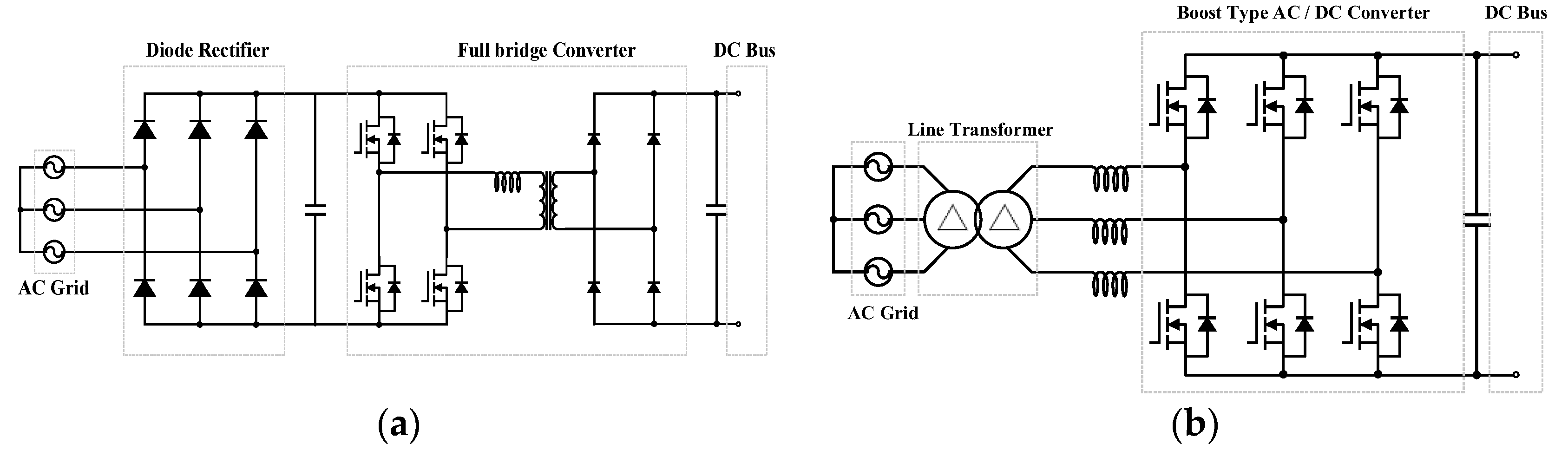
Figure 2 shows the conventional system configuration, which can step down the DC-link voltage from the AC grid voltage. In the case of Figure 2a, the diode rectifier and the full-bridge DC-DC converter [13] are used to configure a two-stage structure. The DC-link voltage is built up by the diode rectifier. Then, the full-bridge DC-DC converter steps down the DC voltage level. In the case of Figure 2b, the line-frequency transformer and the boost-type AC-DC rectifier [4,5,6,7,8] are used. Since the boost-type AC-DC rectifier cannot step down the voltage level, the line-frequency transformer is connected to the grid for stepping down the AC grid voltage. Consequently, the conventional systems require multiple power conversion stages and bulky line-frequency transformers, which degrade their power density and cost-effectiveness. In addition, those systems include the voltage-fed bridge-based topologies, which induce shoot-through problems in the arm switches. In addition, in the case of the diode rectifier, the power factor and THD become poor.

Figure 2.
Conventional topologies: (a) diode rectifier and full-bridge DC-DC converter, (b) boost-type AC-DC rectifier with line transformer.
2.2. Proposed System Structure
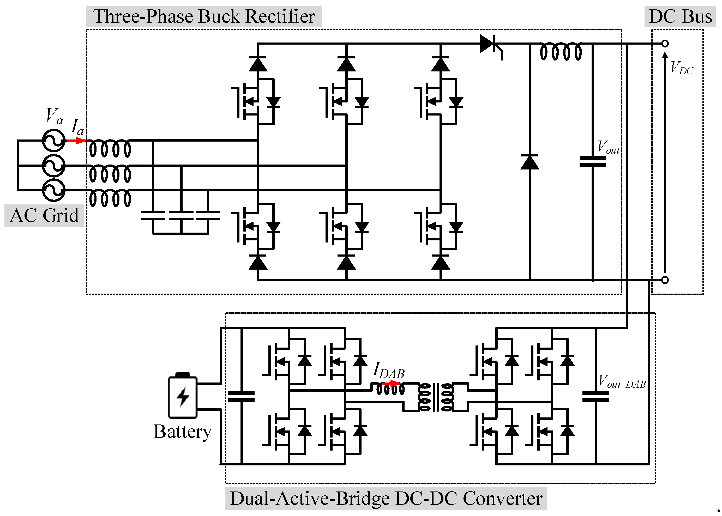
Aiming to obtain high reliability of the DC distribution system, the proposed system is designed as shown in Figure 3. It consists of a single-stage three-phase buck rectifier with a thyristor and an UPS using a DAB converter. Consequently, the structure of the three-phase buck rectifier with the thyristor and the UPS with a protection algorithm can enhance the system reliability. They are being discussed in detail in the following subsections.
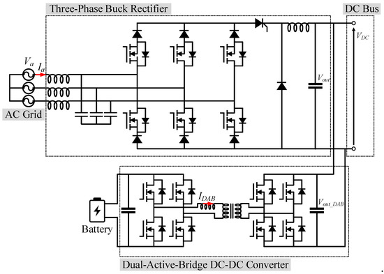
Figure 3.
Schematic of the proposed system.
2.3. Three-Phase Buck Rectifier with Thyristor
In this section, two advantages of the proposed rectifier for the high system reliability are introduced. The first advantage is that the thyristor can be added in the rectifier without any commutation circuits to fully disconnect the circuit under fault conditions. Second, the diode and the switch are connected in series so that the output voltage can be regulated even in the switch-short fault condition. Those advantages can increase the system reliability under the various power switch and system faults.
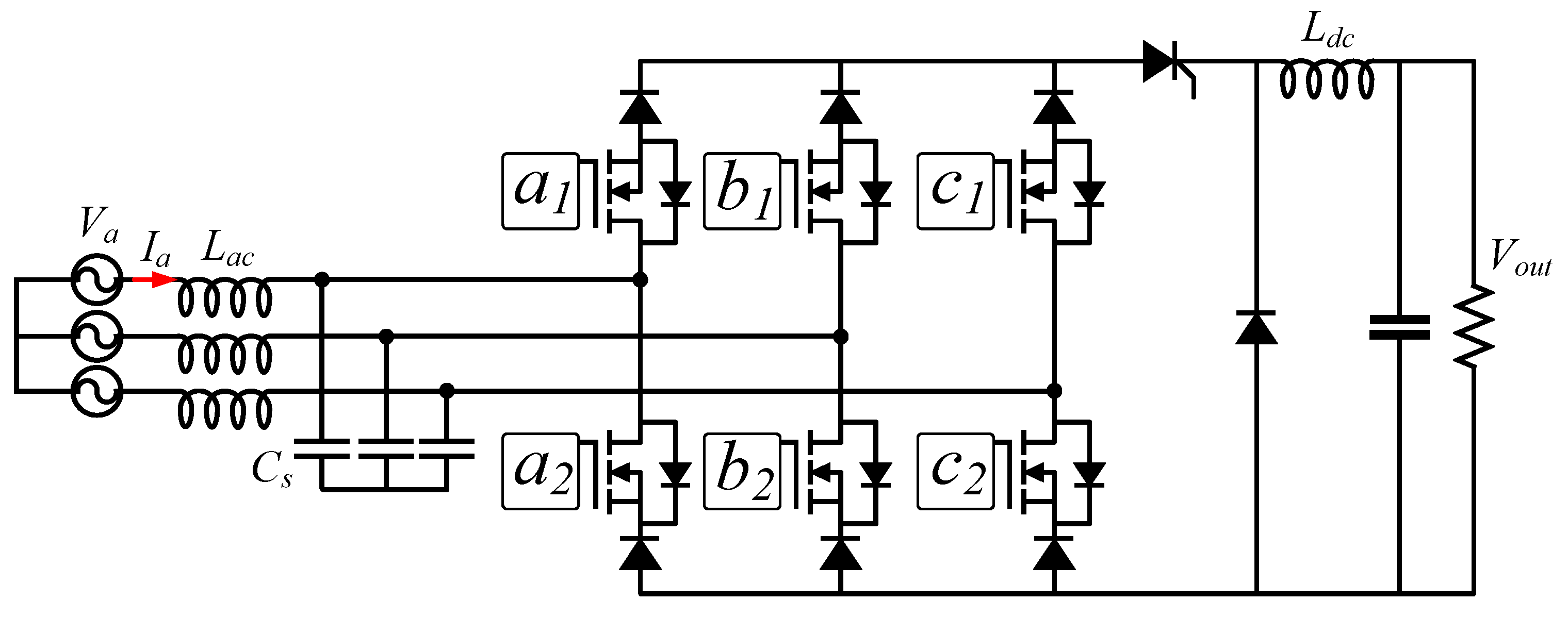
Figure 4 illustrates the schematic of the proposed three-phase buck rectifier employing the thyristor. The input filter consists of three inductors and capacitors. Six MOSFETs and six diodes are used in the bridge structure, and an additional diode is used for freewheeling operation. The output filter is the second-order LC.

Figure 4.
Schematic of the proposed three-phase buck rectifier.
The conventional AC-DC rectifiers, including the buck rectifier, cannot isolate the output terminal under a fault case [4,5,6,7,8,11,12]. Therefore, the system can be damaged by using the conventional rectifier. However, the proposed buck rectifier applied the thyristor switch to protect the system. The thyristor is used to connect and to disconnect the bridge and the freewheeling diode to isolate the output stage from the power source under the fault conditions.
Mechanical relays or semiconductor devices can be used in the DC side to disconnect the circuit from the AC grid. However, the mechanical relays suffer from the arc problem due to its mechanical contacts [14]. MOSFETs are temperature-sensitive and less robust devices. Furthermore, a single MOSFET cannot completely disconnect the circuit due to its antiparallel diode, where two MOSFETs should be required to block the bidirectional power flows. Consequently, to obtain a highly reliable system, the thyristor is chosen by regarding its high robustness and high voltage and current ratings [15].
To completely turn off the thyristor, the current passing from the anode to the cathode should be zero with a turn off signal assigned to the gate. The gate signal can be easily controlled; however, the anode to cathode current needs to be zero, which requires additional commutation circuits [15]. The commutation circuit decreases the power density and the cost-effectiveness. However, as shown in Figure 4, in the proposed structure, the thyristor is designed to be located between the bridge and the freewheeling diode, which enables to turn it off without any additional commutation circuits.
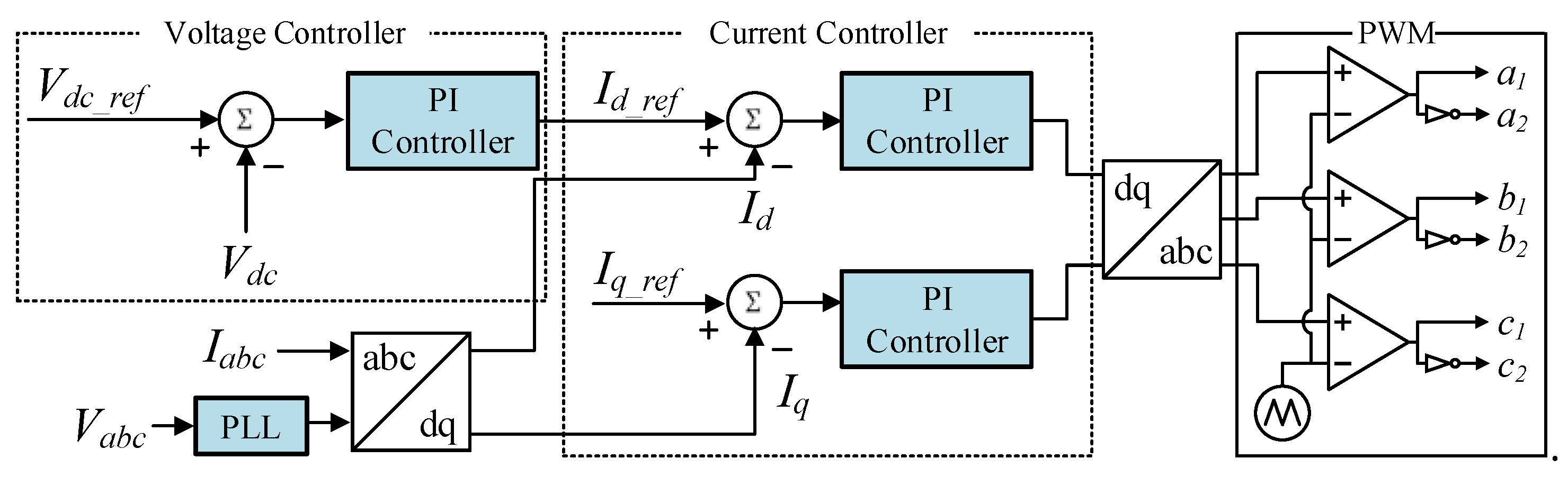
The control scheme of the three-phase buck rectifier is illustrated in Figure 5. The measured output voltage is compared with the reference voltage level, and the PI controller generates a current reference to regulate the output voltage level. The current reference is inserted to the other PI controller to perform the current control. The current control divides the d-axis and the q-axis of the current reference to manage the current magnitude and the phase to obtain a unity power factor [16]. Finally, the output of the PI controller is compared with the triangular waveform to generate the gate signals, which is called the PWM modulation.

Figure 5.
Control block diagram.
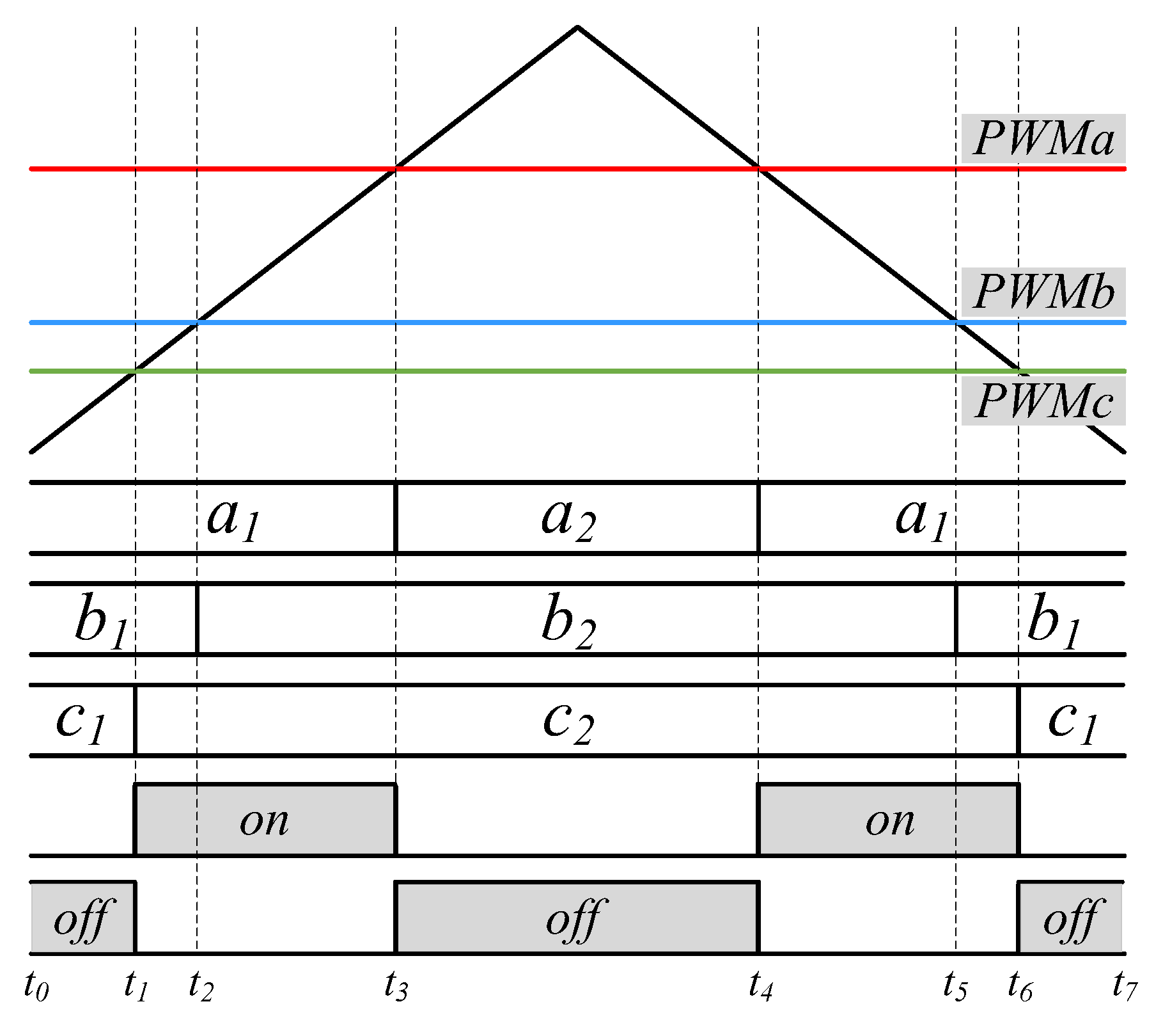
The operation of the buck rectifier can be classified into the on and off states, which is similar to the DC-DC buck converter [17]. The switching modulation scheme with two operating states and operating modes are shown in Figure 6 and Figure 7, respectively. Similar to the DC-DC buck converter, both the on and off states are needed to step down the output voltage. The off state occurs when the switches a1, b1, and c1 or a2, b2, and c2 are turned on. In this state, the current only passes through the freewheeling diode, as shown in Figure 7a,d. The input current from the AC grid cannot flow due to the diodes. Therefore, the current at the thyristor is zero at this state, which can turn off the thyristor. The other region is the on-state, where the current flows from the AC grid to the output stage, as shown in Figure 7b,d. The on- and off-states are formed alternately during the operation. Therefore, the thyristor can be completely turned off at the off-state once the turn-off signal is generated. If the thyristor is attached in the other place except the position shown in Figure 4, the thyristor cannot be turned off because the current still flows through the thyristor.
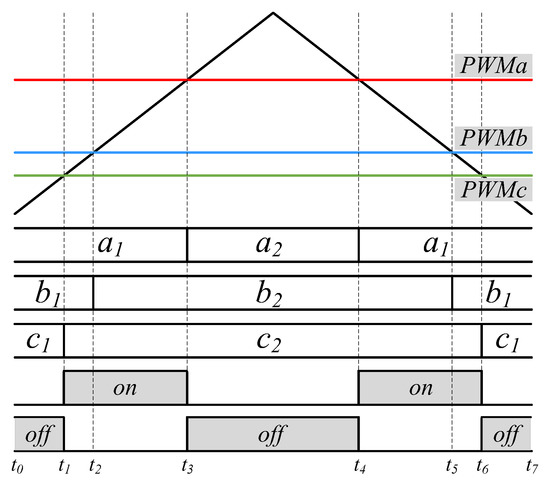
Figure 6.
Switching modulation scheme describing on and off-state.
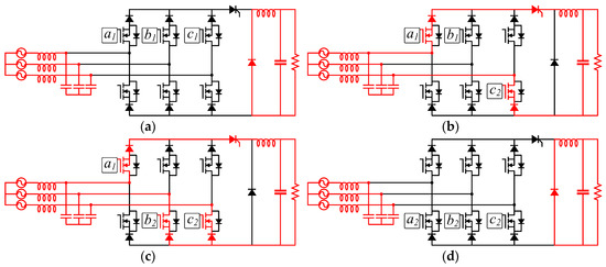
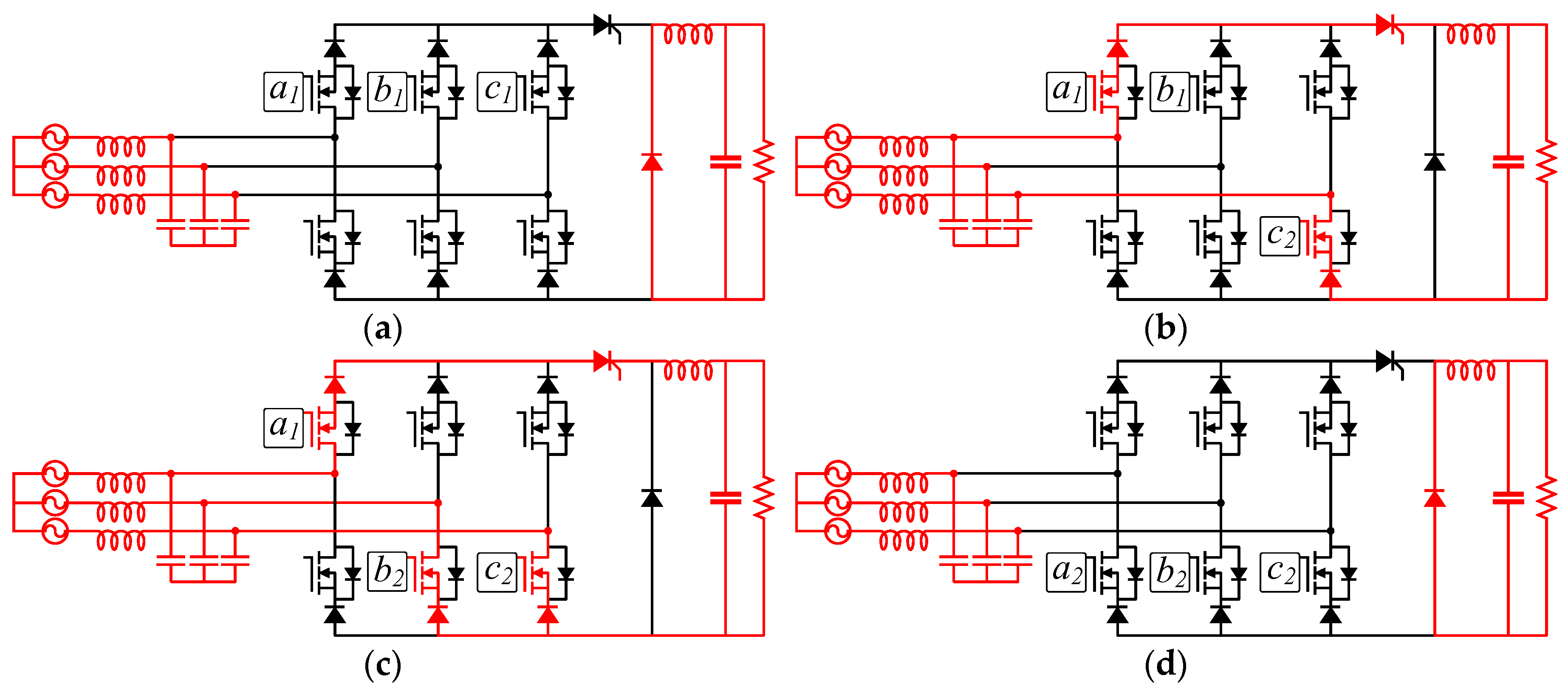
Figure 7.
Operating modes: (a) Mode 1 (t0-t1, off-state), (b) Mode 2 (t1-t2, on-state), (c) Mode 3 (t2-t3, on-state), (d) Mode 4 (t3-t4, off-state).
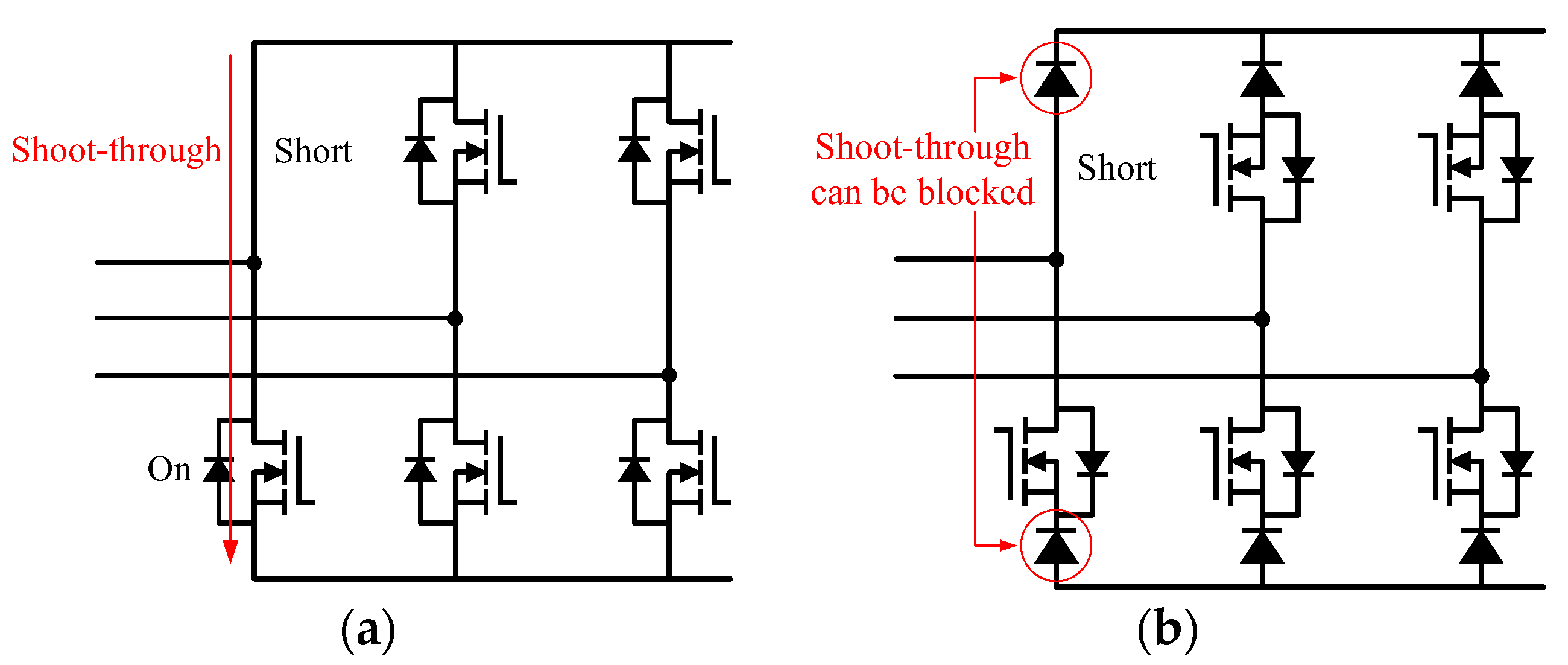
Compared with the conventional boost type AC-DC rectifier, the buck rectifier can obtain the high reliability by preventing the shoot-through fault. As shown in Figure 8a, when a switch is shorted as a fault case in the conventional boost type rectifier, the shoot-through occurs and the output voltage level cannot be regulated, leading to a zero voltage. However, in the proposed buck rectifier shown in Figure 8b, the shoot-through fault can be blocked by the reverse withstanding of the diodes. The diodes are generally much stronger against failures compared with power switches, such as MOSFETs. In other words, the MOSFETs are more likely to be shorted to cause failures. Therefore, even if the buck rectifier has more diodes than the conventional AC-DC rectifier to cause component failures, it is more robust against failures than the conventional system.
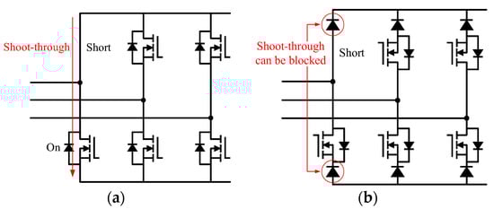
Figure 8.
Shoot-through fault on bridge topologies: (a) boost-type rectifier, (b) buck-type rectifier.
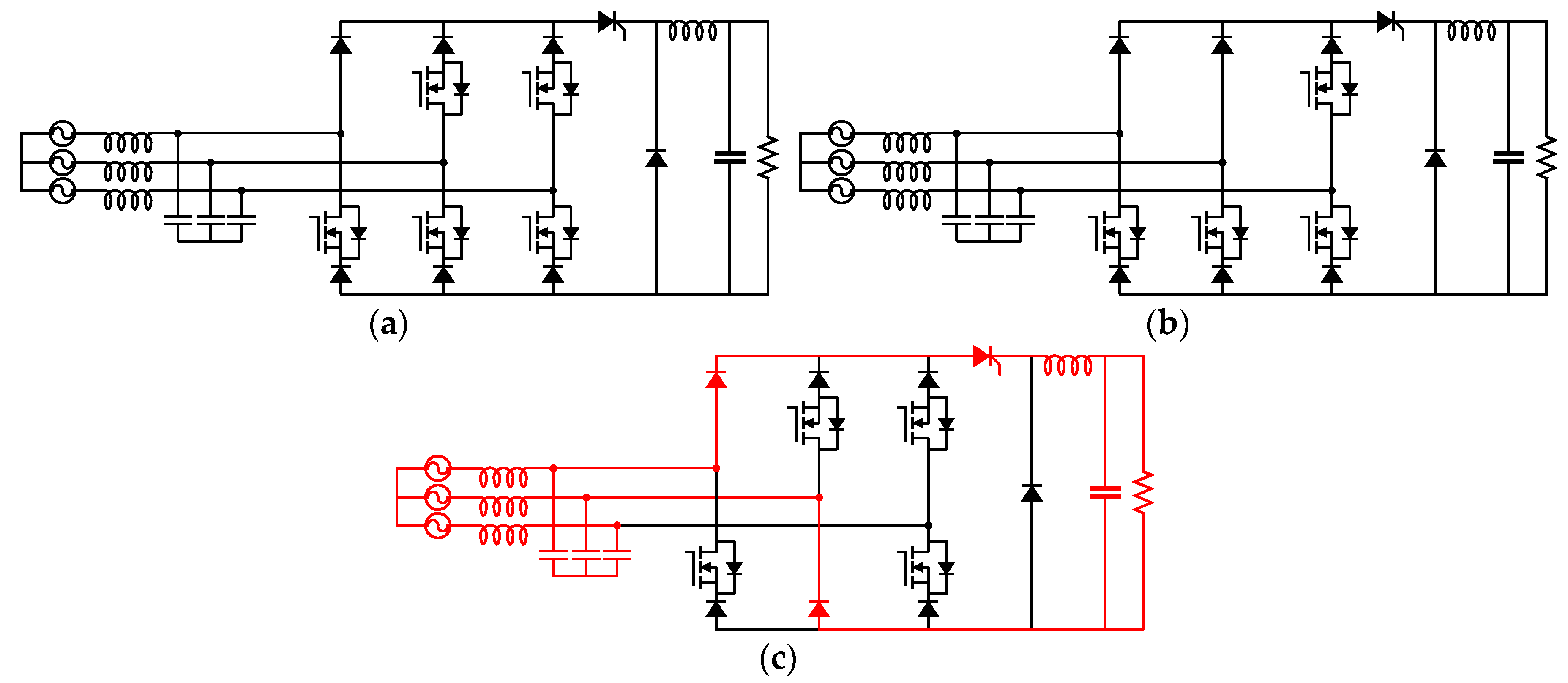
Compared with the conventional buck rectifiers [11,12], the operating reliability against the switch-short conditions is well verified, and the isolation capability to protect the output terminal from the AC grid is given by the proposed buck rectifier. Since the shoot-through fault can be prevented in the buck rectifier, during the short-switch fault, the output voltage can still be regulated to the reference voltage level, as shown in Figure 9. The output voltage can be regulated if both the on- and off-states of the thyristor can be properly selected according the fault condition. In the case of Figure 9a,b, when the single switch and two switches in parallel are shorted, the on- or off-state is not determined since they can be selected according to the switching modulation. However, when the two diagonal switches are shorted, as shown in Figure 9c, the on-state can be frequently selected regardless of the switching modulation, which makes the converter difficult to regulate the output voltage. As a result, the output voltage can be well regulated even when the single or the parallel switches are shorted, which leads to the high reliability of the proposed power conversion system. However, since the faulty bridges cannot be perfectly controlled, the output voltage ripple can be increased during the fault conditions, which is being verified in the next section of experimental results.
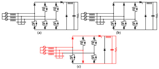
Figure 9.
Fault cases when: (a) one switch is shorted, (b) two parallel switches are shorted, (c) two diagonal switches are shorted.
2.4. Dual-Active-Bridge Converter with Protection Algorithm
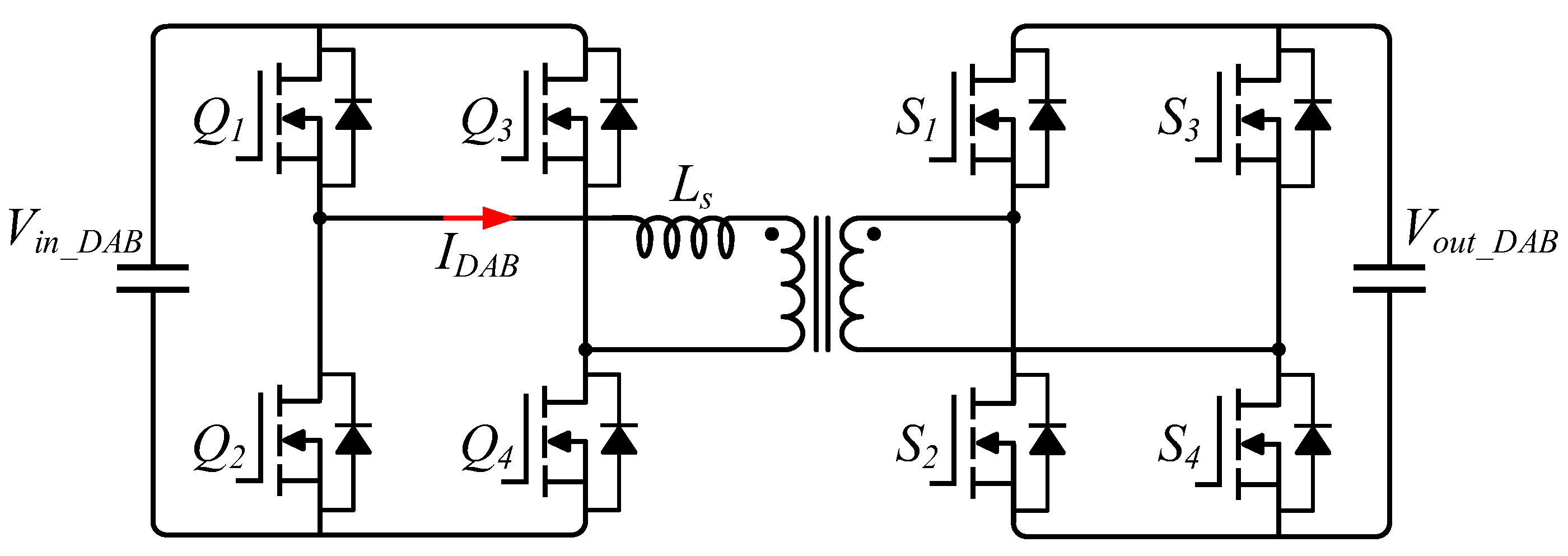
When the thyristor is turned off, there is no power supply connected to the DC bus, where the DC-link voltage of the DC bus cannot be maintained. Therefore, as shown in Figure 3, the DAB converter employing the battery is proposed as a UPS to stabilize the DC-link voltage of the DC bus. The DAB converter shown in Figure 10 has been widely used in DC distribution systems, and it is selected for the UPS due to its various advantages, such as a bidirectional power flow capability, a zero voltage switching (ZVS) capability, and a galvanic isolation [18]. Compared with the conventional DC-DC converters used for UPS system [9,10], the DAB converter can provide the galvanic isolation to protect users from electric shocks, which is important to preserve the user safety. Since the DAB converter has the bidirectional power flow capability, the battery shown in Figure 3 can be fully charged and discharged to supply the electric power to the DC bus.
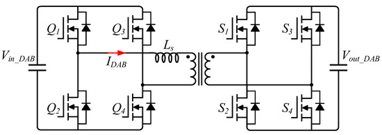
Figure 10.
Schematic of dual-active-bridge (DAB) DC-DC converter.
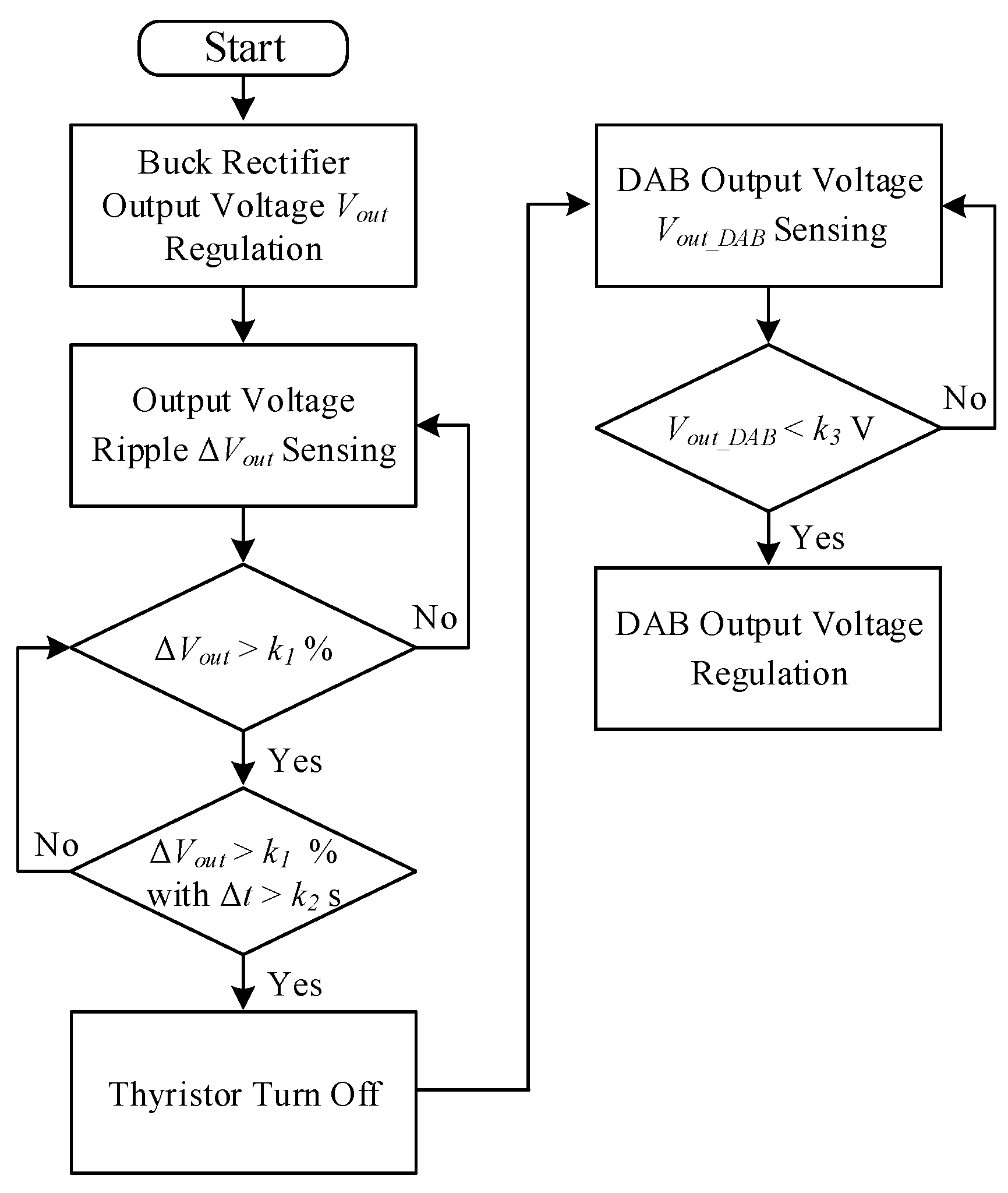
To successfully stabilize the DC-link voltage under the fault conditions, the protection algorithm of the buck rectifier and the DAB converter is proposed in Figure 11. When the switch of the buck rectifier has the short-fault, the faulty bridge loses its controllability and the output voltage ripple is increased. Therefore, in the first protection process of the proposed algorithm, the output voltage ripple is used to detect this fault condition. If the output voltage ripple increases at a certain point, the thyristor is turned off to protect the output stage. In the case of the load transient, which can increase the voltage ripple, the output voltage ripple detection collects the voltage ripple data during a specific time to determine the on- of off-state of the thyristor. After the thyristor is turned off, the output voltage starts to decrease due to the absence of the power source. When the output voltage is decreased to a specific voltage level, the DAB converter supplies the electric power from the battery to the output stage to regulate the DC-bus voltage.
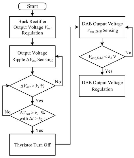
Figure 11.
Flowchart of the proposed protection algorithm.
3. Experimental Results
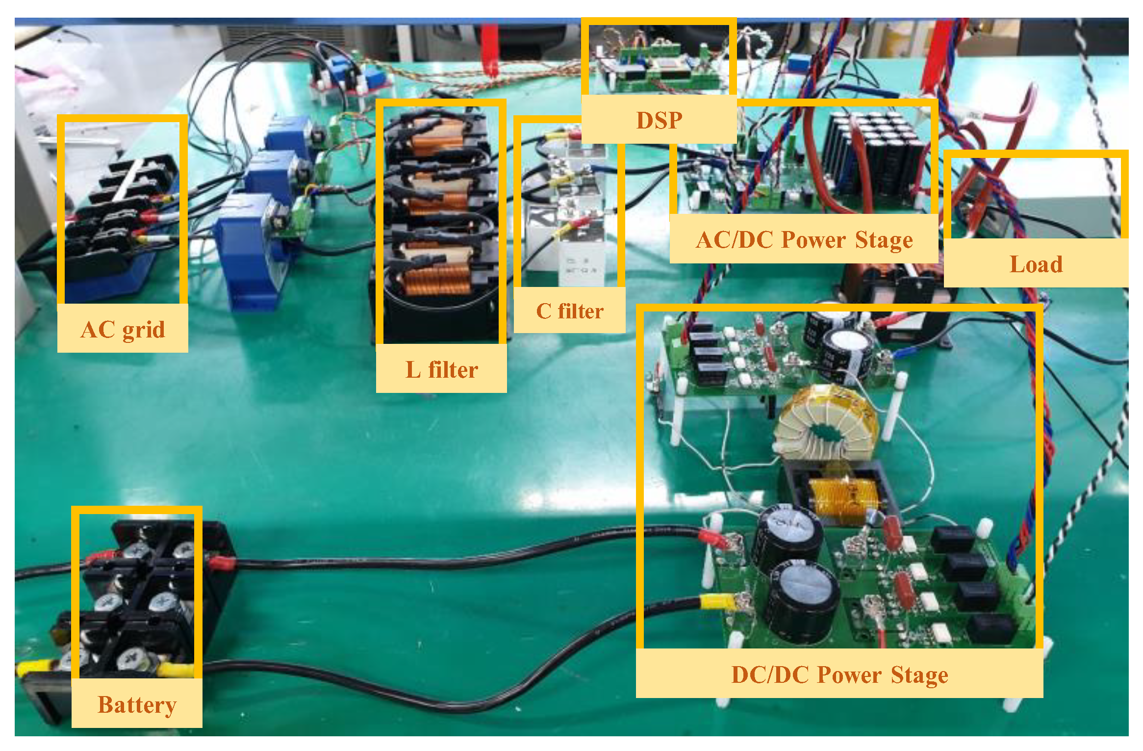
The specifications of a 3.6-kw prototype converter are listed in Table 1. The experimental setup is shown in Figure 12. The line-to-line grid voltage connected to the input of the converter is 220 V. In the case of the diode rectifier or the boost-type AC-DC converter, the regulated minimum output DC voltage level is 311 V. However, under the proposed system configuration, the DC output can be regulated by stepping down to 110 V, which is the target voltage level. The buck rectifier is connected to the AC grid, and the DAB converter is interfaced between the output stage and the battery to operate as the UPS. The PWM signals and the protection algorithm are implemented by a digital signal processor of TMS320F28335 manufactured by Texas Instrument (TI).

Table 1.
System Parameters.

Figure 12.
Photograph of experimental setup.
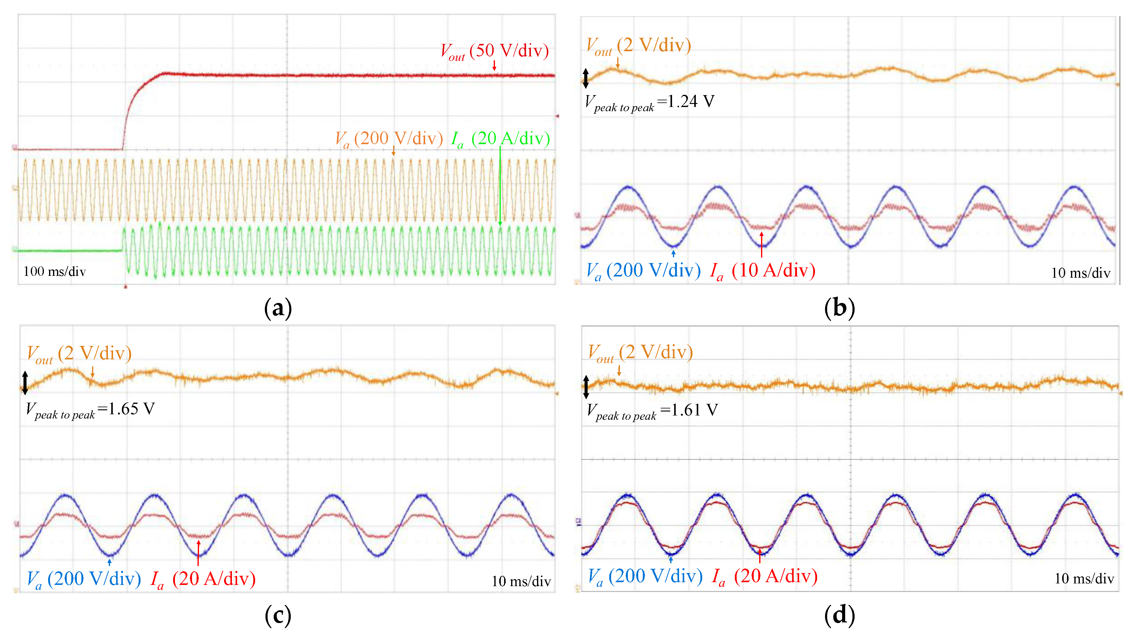
Figure 13 shows the experimental results of the buck rectifier. Va, Ia, and Vout are the grid input voltage, grid input current, and output DC voltage, respectively. In Figure 13a, the output voltage of the buck rectifier is well regulated to 110 V. The steady-state waveforms under various load conditions are depicted in Figure 13b–d according to the output power. The input grid current is regulated to have the same phase with the grid voltage for the unity power factor and the low THD. The measured power factor and THD of Figure 12d is 0.99% and 9.2%, respectively. In the condition of Figure 13, the power switches are not under the fault condition. The output voltage ripples are less than 2 V in the normal condition; however, the voltage ripples are expected to increase under the faulty cases.
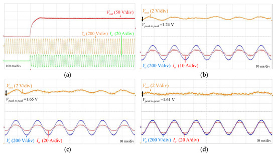
Figure 13.
Experimental waveforms of the proposed buck rectifier: (a) Transient operation, (b) Pout = 800 W, (c) Pout = 1700 W, (d) Pout = 3600 W.
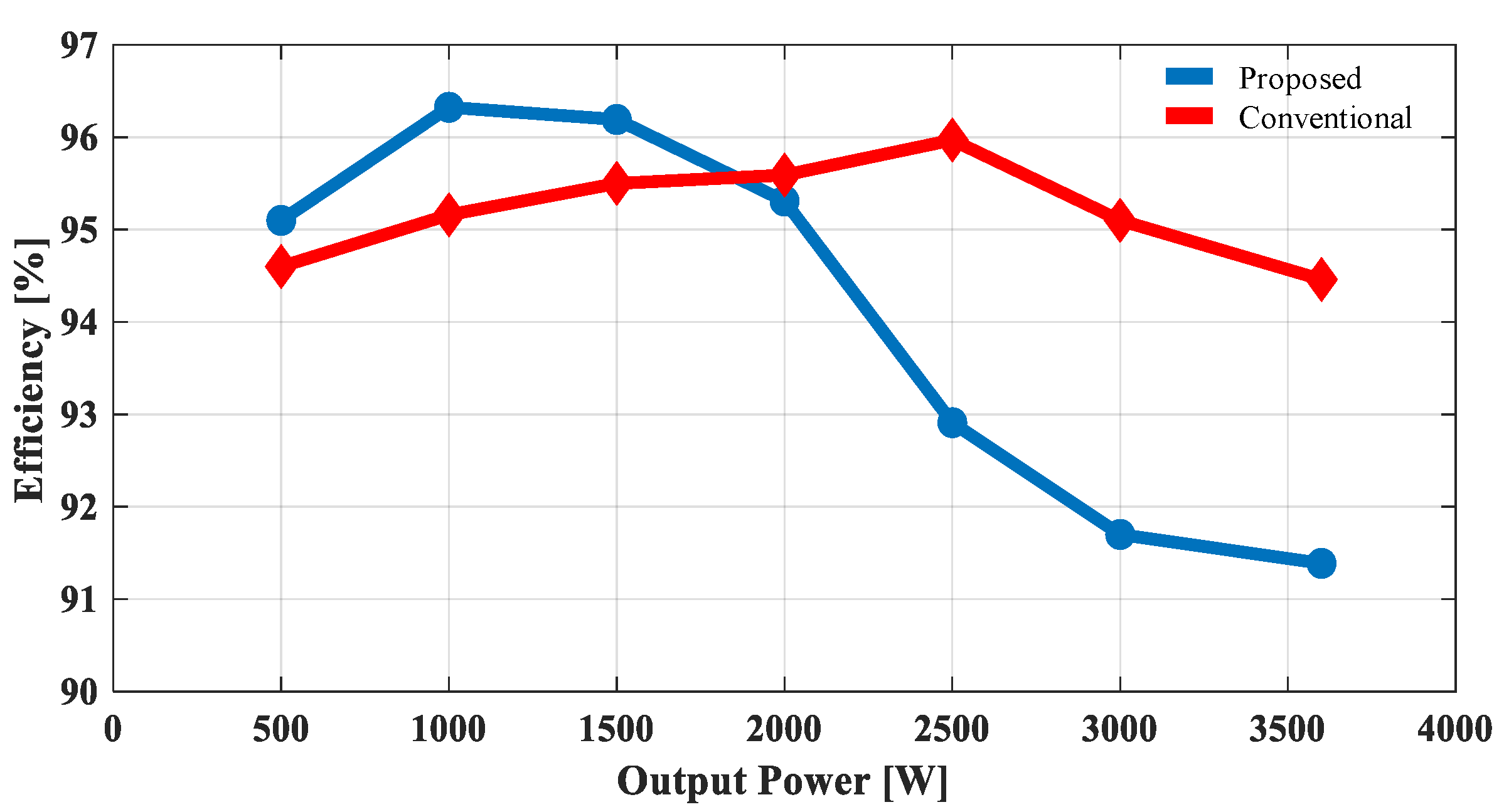
The power conversion efficiency curves of the proposed buck rectifier and the conventional voltage source inverter are shown in Figure 14. The blue circle marked curve and the red diamond marked curve shows the efficiency of the proposed buck rectifier and the conventional voltage source inverter, respectively. In the proposed buck rectifier, the peak efficiency is 96.324% at 1000 W, and the overall efficiency is higher than 91%. The efficiency decreases as the output power rises because of the conduction loss increment. Figure 15 shows the loss breakdown at 1000 and 3600 W. As seen, the conduction loss of the MOSFET at 3600 W is bigger than that of 1000 W compared with the other power losses, which decreases efficiency as output power goes up.
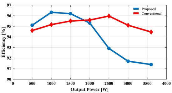
Figure 14.
Power conversion efficiency curve of the proposed buck rectifier.
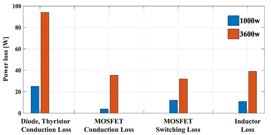
Figure 15.
Loss breakdown at the output power of 1000 and 3600 W.
Comparing with the conventional voltage-fed bridge rectifiers, the proposed buck rectifier has a demerit in terms of the conduction loss because it has additional power diodes connected to the bridge in series and thyristor. There is a trade-off between the reliability and the efficiency in the proposed converter, which depends on the target applications. Therefore, at high power conditions, the efficiency of the proposed converter is lower than that of the conventional converter due to large conduction losses caused by diodes and the thyristor.
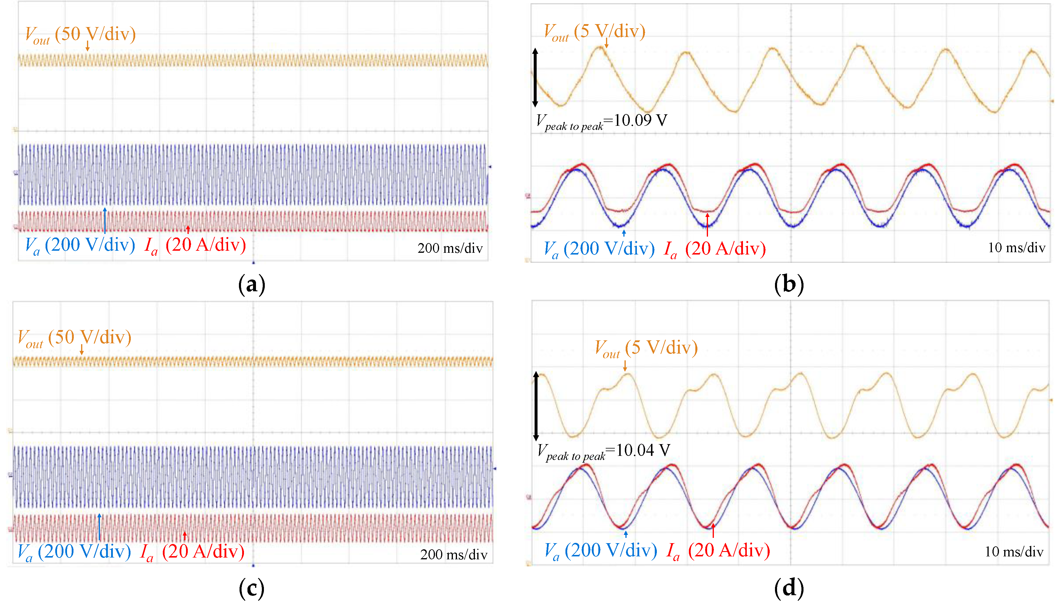
Figure 16 shows the output voltage regulation under the switch fault conditions. A single switch a1 and two parallel switches a1 and b1 are shorted to make the fault situation in Figure 16a,c, respectively. Even if the switches are shorted, the series-connected diodes can block the shoot-through so that the output voltage is not collapsed. The shorted switches cannot be controlled; however, other normal switches can still be controlled by the modulation algorithm shown in Figure 5. Therefore, in Figure 15a,c, the output voltage is well regulated to 110 V, but the voltage ripples are increased from 2 (shown Figure 13) to 10 V, as shown in Figure 16b,d. These experimental waveforms verify that the level of the voltage ripple can be used as an indicator to detect the fault conditions, which are used for the proposed protection algorithm.
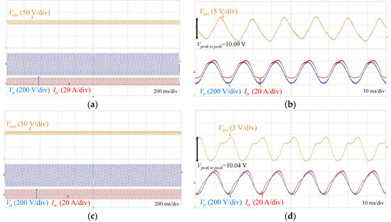
Figure 17 shows the operation of the buck rectifier with the DAB converter under the switch fault condition. As shown in the left side waveforms of Figure 17, the output voltage can be regulated under the switch fault condition within 10 V peak-to-peak voltage ripples. After the detection of this fault, the thyristor is turned off by using the proposed protection algorithm. This fault condition is the same as that of Figure 16a. After the faulty circuit is isolated from the AC grid, the output voltage naturally decreases. When the output voltage is decreased to 90 V, the DAB converter operates as the UPS to supply the electric power to the DC grid. Then, the output voltage is recovered to 110 V within 60 ms by the voltage regulation of the DAB converter. Consequently, shown in Figure 17, the output voltage can be properly regulated under the high reliability guaranteed by the proposed buck rectifier, the series-connected thyristor, and the protection algorithm, even if the switch fault occurs in the proposed system.
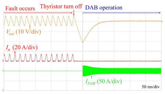
Figure 17.
Output voltage regulation using the proposed protection algorithm and DAB converter.
4. Conclusions
The AC-DC power conversion system is proposed for the DC grid application, which requires high reliability against various fault conditions. It consists of the three-phase buck rectifier and the DAB converter employing the battery to obtain the UPS capability. In the proposed system, the series-connected thyristor is used to disconnect the output stage from the faulty system without any additional devices. Therefore, the proposed three-phase buck rectifier employing the thyristor can completely isolate the output stage from the AC grid under the fault conditions. Before the disconnection under the fault conditions, the three-phase buck rectifier can regulate the output voltage with the increased voltage ripple, which is a great benefit of the proposed system in the reliability manner. The protection algorithm and the DAB converter operating as the UPS can also maintain the output voltage after the disconnection by the series-connected thyristor. The effectiveness of the proposed system is verified by a 3.6-kW prototype with an output voltage level of 110 V. The overall efficiency of the buck rectifier is high, and the peak efficiency is 96.324%. The power factor and THD is 0.99% and 9.2%, respectively. Even under the short-switch faults, the buck rectifier can regulate the output voltage level to 110 V with 10 V peak-to-peak voltage ripples. By using the protection algorithm, after the short-switch occurs, the thyristor is turned off, and the DAB converter restores the output voltage to 110 V within 60 ms, which guarantees a highly reliable DC power.
Author Contributions
Conceptualization, J.-Y.L. and J.-H.J.; Methodology, J.-Y.L., K.-W.H., and K.-T.K.; Experiment and verification, J.-Y.L. and K.-W.H.; Writing-original draft, J.-Y.L. and J.-H.J.; Supervision and guide, J.-H.J. All authors have read and agreed to the published version of the manuscript.
Funding
This research was funded by SAMSUNG ELECTRONICS Co. Ltd., grant number 2.190683.01.
Conflicts of Interest
The authors declare no conflict of interest.
References
- Elsayed, A.T.; Mohamed, A.A.; Mohammed, O.A. DC Microgrids and Distribution Systems: An Overview. Electr. Power Syst. Res. 2015, 119, 407–417. [Google Scholar] [CrossRef]
- AlLee, G.; Tschudi, W. Edison redux: 380 Vdc brings reliability and efficiency to sustainable data centers. IEEE Power Energy Mag. 2012, 10, 50–59. [Google Scholar] [CrossRef]
- Joseph, S.C.; Dhanesh, P.R. Lvdc architecture for residential application. In Proceedings of the 2016 IEEE International Conference on Power Electronics, Drives and Energy Systems (PEDES), Trivandrum, India, 14–17 December 2016; pp. 1–4. [Google Scholar]
- Wu, T.F.; Kuo, C.L.; Sun, K.H.; Chang, Y.C. DC-bus voltage regulation and power compensation with bi-directional inverter in dc-microgrid applications. In Proceedings of the 2011 IEEE Energy Conversion Congress and Exposition, Phoenix, AZ, USA, 17–22 September 2011; pp. 4161–4168. [Google Scholar]
- Lin, B.R.; Hung, Z.L. A single-phase bidirectional rectifier with power factor correction. In Proceedings of the IEEE Region 10 International Conference on Electrical and Electronic Technology, Singapore, 19–22 August 2001; Volume 2, pp. 601–605. [Google Scholar]
- Zhu, Q.; Wang, L.; Zhang, L.; Yu, W.; Huang, A.Q. Improved medium voltage AC-DC rectifier based on 10kV SiC MOSFET for Solid State Transformer (SST) application. In Proceedings of the 2016 IEEE Applied Power Electronics Conference and Exposition (APEC), Long Beach, CA, USA, 20–24 March 2016; pp. 2365–2369. [Google Scholar]
- Celanovic, N.; Boroyevich, D. A comprehensive study of neutral-point voltage balancing problem in three-level neutral-point-clamped voltage source PWM inverters. IEEE Trans. Power Electron. 2000, 15, 242–249. [Google Scholar] [CrossRef]
- Rabkowski, J.; Sak, T.; Strzelecki, R.; Grabarek, M. SiC-based T-type modules for multi-pulse inverter with coupled inductors. In Proceedings of the 2017 11th IEEE International Conference on Compatibility, Power Electronics and Power Engineering (CPE-POWERENG), Cadiz, Spain, 4–6 April 2017; pp. 568–572. [Google Scholar]
- Aamir, M.; Mekhilef, S.; Kim, H.J. High-Gain Zero-Voltage Switching Bidirectional Converter with a Reduced Number of Switches. IEEE Trans. Circuits Syst. II 2015, 62, 816–820. [Google Scholar]
- Pires, V.F.; Foito, D.; Cordeiro, A. A DC–DC Converter with Quadratic Gain and Bidirectional Capability for Batteries/Supercapacitors. IEEE Trans. Ind. Appl. 2018, 54, 274–285. [Google Scholar] [CrossRef]
- Stupar, A.; Friedli, T.; Minibock, J.; Kolar, J.W. Towards a 99% Efficient Three-Phase Buck-Type PFC Rectifier for 400-V DC Distribution Systems. IEEE Trans. Power Electron. 2012, 27, 1732–1744. [Google Scholar] [CrossRef]
- Guo, B.; Wang, F.; Burgos, R.; Aeloiza, E. Control of three-phase buck-type rectifier in discontinuous current mode. In Proceedings of the 2013 IEEE Energy Conversion Congress and Exposition, Denver, CO, USA, 15–19 September 2013; pp. 4864–4871. [Google Scholar]
- Safaee, A.; Jain, P.K.; Bakhshai, A. An Adaptive ZVS Full-Bridge DC–DC Converter with Reduced Conduction Losses and Frequency Variation Range. IEEE Trans. Power Electron. 2015, 30, 4107–4118. [Google Scholar] [CrossRef]
- Kamtip, S.; Bhumkittipich, K. Comparison between mechanical circuit breaker and solid state circuit breaker under abnormal conditions for low voltage systems. In Proceedings of the 2015 18th International Conference on Electrical Machines and Systems (ICEMS), Pattaya, Thailand, 25–28 October 2015; pp. 1091–1096. [Google Scholar]
- Guo, Y.; Wang, G.; Zeng, D.; Li, H.; Chao, H.A. Thyristor Full-Bridge-Based DC Circuit Breaker. IEEE Trans. Power Electron. 2020, 35, 1111–1123. [Google Scholar] [CrossRef]
- Kazmierkowski, M.P.; Malesani, L. Current control techniques for three-phase voltage-source PWM converters: A. survey. IEEE Trans. Ind. Electron. 1998, 45, 691–703. [Google Scholar] [CrossRef]
- Rivetta, C.H.; Emadi, A.; Williamson, G.A.; Jayabalan, R.; Fahimi, B. Analysis and control of a buck DC-DC converter operating with constant power load in sea and undersea vehicles. IEEE Trans. Ind. Appl. 2006, 42, 559–572. [Google Scholar] [CrossRef]
- Zhao, B.; Song, Q.; Liu, W.; Sun, Y. Overview of Dual-Active-Bridge Isolated Bidirectional DC–DC Converter for High-Frequency-Link Power-Conversion System. IEEE Trans. Power Electron. 2014, 29, 4091–4106. [Google Scholar] [CrossRef]


© 2020 by the authors. Licensee MDPI, Basel, Switzerland. This article is an open access article distributed under the terms and conditions of the Creative Commons Attribution (CC BY) license (http://creativecommons.org/licenses/by/4.0/).