Article

Effect of Suction and Discharge Conditions on the Unsteady Flow Phenomena of Axial-Flow Reactor Coolant Pump

1
College of Energy Engineering, Zhejiang University, Hangzhou 310027, China
2
State Key Laboratory of Fluid Power Transmission and Control, Hangzhou 310027, China
*
Author to whom correspondence should be addressed.
Energies 2020, 13(7), 1592; https://doi.org/10.3390/en13071592
Submission received: 11 February 2020 / Revised: 19 March 2020 / Accepted: 23 March 2020 / Published: 1 April 2020
(This article belongs to the Special Issue Next Generation of Hydraulic Machines)

Abstract

:
In order to study the effects of the suction and discharge conditions on the hydraulic performance and unsteady flow phenomena of an axial-flow reactor coolant pump (RCP), three RCP models with different suction and discharge configurations are analyzed by computational fluid dynamics (CFD) method. The CFD results are validated by experimental data. The hydraulic performance of the three RCP models shows little difference. However, the unsteady flow phenomena of RCP are significantly affected by the variation of suction and discharge conditions. Compared with that of Model E-S (baseline, elbow-single nozzle), the pressure pulsation in rotating frame of Model S-S (straight pipe-single nozzle) and Model E-D (elbow-double nozzles) is weakened in different degrees and forms, due to the more uniform flow fields upstream and downstream of the impeller, respectively. It indicates that the generalized rotor-stator interaction (RSI) actually exists between the rotating impeller and all stationary components causing the circumferentially non-uniform flow. Furthermore, improving the circumferential uniformity of the flow upstream and downstream of impeller (suction and discharge flow) also contributes to reducing the radial dynamic fluid force acting on the impeller. Compared with those of Model E-S, the dynamic FX and FY of Model S-S are severely weakened, and those of Model E-D also gain a minor amplitude decrease at fBPF. In contrast, the general pressure pulsation in fixed frame is mainly related to the rotating impeller and barely affected by the suction and discharge conditions.

1. Introduction

The pressure pulsation and dynamic fluid force of internal unsteady flow have significant influences on the performance and operation reliability of turbomachinery. They may result in excessive vibration and noise, and even lead to the fatigue failure of components. Due to significant fluid-dynamic perturbations, these unsteady flow phenomena have attracted the extensive attention of researchers.
The reactor coolant pump (RCP) is a key piece of equipment in a nuclear power plant. It is used to force the coolant circulating in the primary loop of the pressurized water reactor (PWR), thus transferring heat from the nuclear fuel core to the steam generator [1]. The operation reliability of RCP is directly related to the safety of the nuclear power plant, which makes it particularly crucial and significant to study the flow instabilities in RCP. In recent years, a number of relevant studies have been conducted for a mixed-flow RCP with the radial diffuser and spherical casing. Long et al. [2,3] experimentally investigated the pressure pulsation of this mixed-flow RCP under different flow rates and rotational speeds. Ni et al. [4] studied the pressure pulsation, vorticity fluctuation, and unsteady flow structure in the mixed-flow RCP, and discussed the correlation among them. Additionally, the unsteady flow phenomena in an uncommon mixed-flow RCP with an eccentric impeller were also investigated by Tao et al. [5]. However, with regard to the axial-flow RCP which is also widely used in nuclear power plants, the unsteady flow phenomena and the relevant characteristics are barely studied. Furthermore, even for the general axial-flow pump, there are only a few relevant studies reported. Zhang et al. [6] investigated the pressure pulsation as well as the pressure and velocity distribution in the axial-flow pump. Xie et al. [7] compared the pressure pulsation in an axial-flow prototype pump and its scaled model. Chen et al. [8] studied the pressure pulsation, vibration acceleration, and noise of an axial-flow pump. Further research on the unsteady flow of axial-flow pump is still required, especially for the axial-flow RCP.
The unsteady flow phenomena in pumps are fundamentally related to the geometric structure of the flow-passing components. In order to study the effects of various geometry parameters on unsteady flow in pumps, extensive researches have been conducted. In most researches, the geometry modifications of impeller were considered. Gao et al. [9] investigated the effect of the impeller blade trailing edge profile on the pressure pulsation of a centrifugal pump with low specific speed, and discussed the reason through the analysis of vorticity distribution. González et al. [10] studied the steady and unsteady radial fluid forces in two volute centrifugal pumps with different impeller diameters and thereby different tongue gaps as well. Using different research methods, Spence et al. [11], Fu et al. [12], and Song et al. [13] respectively investigated the effect of the impeller stagger angle on the double-suction centrifugal pump. Spence et al. [14] then conducted a parametric study investigating the effects of four impeller geometric features on the pressure pulsation. For the mixed-flow pump, Hao et al. [15] studied the effects of tip clearance size and symmetry on the radial fluid force. With respect to the geometry of diffuser, Guo et al. [16,17] carried out an experimental study on the pressure pulsation and radial fluid force of a centrifugal pump with a varying number of diffuser vanes. For the mixed-flow RCP mentioned before, Ni et al. [18] studied the effect of diffuser vane trailing edge profile on the pressure pulsation. Five profiles of the diffuser vane trailing edge were designed and the unsteady vorticity distribution was analyzed to reveal the mechanism. Jiang et al. [19] and Wang et al. [20] investigated the effect of the circumferential relative position (clocking position) between the diffuser and volute on centrifugal pumps, by the numerical and experimental methods, respectively. Moreover, Zhang et al. [21,22] proposed a slope volute for the centrifugal pump in their studies and the effects of the volute modification on the flow structure and pressure pulsation were discussed.
In addition to the geometry of the main body components (impeller, diffuser, and volute), the suction and discharge configurations, which determine the inflow and outflow conditions of the pump, also have great effects on unsteady flow phenomena. In a few studies, the effects of the inflow condition have been confirmed and studied. In order to improve the operation stability of the centrifugal pump, Liu et al. [23] designed a series of inlet guide vanes to modify the inflow condition and the effects of the inlet guide vanes on the pressure pulsation and unsteady flow patterns were investigated. For the mixed-flow RCP, Long et al. [24] studied the influences of the non-uniform inflow caused by a special channel head on the pressure pulsation and dynamic radial fluid force. In the research of Van Esch [25], a non-uniform inflow was obtained in the experiments by a flow redistribution device to imitate the situation encountered in the practical installation of a waterjet pump, and the effects of such non-uniform inflow on the performance and radial fluid forces were studied. Moreover, the effects of man-made radial and lateral non-uniform inflows on the pressure pulsation and dynamic radial fluid forces of an axial-flow pump were discussed in the paper of Shi et al. [26]. In reality, the non-uniform inflow of pumps is usually caused by the elbow arranged at the suction inlet of impeller, due to the pipeline layout. Nevertheless, the effect of the elbow at the suction inlet has not been specially studied. On the other side, for security reasons, the casing of RCP is usually designed to be spherical or cylindrical with a one-side radial nozzle for flow discharge. The asymmetric discharge condition is also considered to have an effect on the unsteady flow in the RCP, which needs to be investigated and analyzed in detail.
In this study, three axial-flow RCP models with different suction and discharge conditions are compared. Based on the computational fluid dynamics (CFD) method, the hydraulic performance, pressure pulsation, and dynamic fluid force of the three models are investigated. By the fast Fourier transform (FFT) approach, the frequency spectra of pressure pulsation and dynamic fluid force are obtained and analyzed in detail. The internal flow field, pressure pulsation in rotating frame and rotor-stator interaction (RSI) inside are also discussed to reveal the reasons for the effects of suction and discharge variations.

2. Pump Model

2.1. Main Geometry and Parameters

The pump investigated in this paper is a scale-down model of an axial-flow RCP. This type of axial-flow RCP is widely employed in nuclear power plants (NPPs). The main geometry of the RCP model pump is illustrated in Figure 1. It mainly consists of an unshroud axial-flow impeller, an axial rear diffuser, and a peculiar pump casing. The numbers of the twisted impeller blades and diffuser vanes are 5 and 14, respectively. The pump casing is used to divert flow from the axial direction to the radial direction. Considering the pressure bearing capacity of the structure, the pump casing is designed to be cylinder-shaped with a radial discharge nozzle. The specific speed of the RCP model pump is 120. The other key geometrical and design parameters of it are listed in Table 1.

2.2. Suction and Discharge Configurations

In order to study the effect of the suction and discharge conditions, three RCP models with different suction and discharge configurations are considered in this study, as shown in Figure 2. The three models are termed as E-S, S-S, and E-D, respectively, according to their suction-discharge arrangements (elbow-single nozzle, straight pipe-single nozzle, and elbow-double nozzles).
In detail, Model E-S is the baseline model with the same arrangement as the experiment. A 90° elbow is arranged on the suction side of Model E-S, of which the curvature radius equals to 1.8 times the suction pipe diameter. On the discharge side, the pump casing of Model E-S is the conventional form with single radial discharge nozzle. In contrast, on the suction side of Model S-S, the 90° elbow is replaced by a piece of straight pipe with the same diameter and length. With respect to Model E-D, a new pump casing with double symmetrically distributed discharge nozzles (adding an identical discharge nozzle on the opposite side of the original one) is employed on the discharge side, and the same 90° elbow as that of Model E-S is arranged on the suction side. Beyond this, the impeller and diffuser geometries of the three models remain consistent.

3. CFD Method

3.1. Computational Domain and Meshes

The computational domain of model RCP used in CFD analysis is shown in Figure 3 (taking that of Model E-S as an example). It includes the impeller, diffuser, pump casing, elbow (or straight pipe for Model S-S), and appropriate extension tubes on the suction and discharge sides. In detail, on the suction side of pump, a large-diameter pipe with a reducer downstream is added into the CFD calculation, which is in accordance with the experimental pipeline. On the other side, the discharge tube domain is extra extended by 11 times the pipe diameter to reduce the influence of the outlet boundary and improve the accuracy of calculation. In order to maintain consistency among models, the same suction extension tube domain is appended upstream for Model S-S, and both the double discharge tube domains of Model E-D are extended in the same manner as mentioned above.
The high-quality hexahedral meshes are applied to discretize the whole computational domain, as shown in Figure 3 and 4, by means of the commercial software ANSYS ICEM-CFD. The suitable topology structure of mesh is built for each component according to the specific geometry of it, and the optimized nodes distribution is determined focusing on the mesh quality. Furthermore, the near-wall grid resolution is enhanced to satisfy the demand of the turbulence model, especially for the meshes of impeller, diffuser, and casing, as shown in Figure 4. In particular, 10 layers of grids are arranged within the tiny tip clearance, and the adjacent meshes are also accordingly refined. The corresponding crucial y+ value within the whole computational domain is set in the range between 4 and 260, which is suited to the turbulence model (realizable k-ε model) used in the present study and validated to be appropriate as well. The grid independence investigation is performed on Model E-S at the design flow rate with four different grid numbers, and the results are shown in Table 2. Considering the calculation accuracy and cost, about 4.0 million (4.5 million for Model E-D, due to the double discharge nozzles) grids in total for the whole domain are considered appropriate. The detailed grid number and mean grid volume of each component domain is summarized in Table 3. The minimum and mean determinant 2×2×2 values, which represent the quality of meshes, are 0.38 and 0.94 in the whole domain, respectively.

3.2. Solving Method and Condition

The steady and unsteady three-dimensional RANS equations were solved by the finite volume method in commercial CFD code Ansys Fluent 18.0. The Realizable k-ε model was used to close the RANS equations. The enhanced wall treatment was applied to solve the near-wall flow. The velocity-pressure coupling was dealt with the SIMPLEC scheme. The second-order upwind scheme was used for the spatial discretization of convection terms in the momentum, turbulent kinetic energy, and turbulent dissipation rate equations. The temporal discretization in the unsteady calculation was accomplished by the second-order implicit time integration.
The fluid zones were connected by interface pairs. The rotational motion of the impeller zone was defined by the multi-reference frame model (MRF) in the steady calculation, and then by the sliding mesh model (SMM) in the unsteady calculation. Incompressible water with a density of 998.1 kg/m3 and a viscosity of 1.048 kg/m·s was taken as the working fluid, according to the operating condition in experiment (about 1 atm gauge pressure, 21 °C on the suction side of pump). Two definition schemes of the inlet-outlet boundary conditions were considered and compared in this study. In the first scheme, the constant gauge total pressure (103.5 kPa) was given at the inlet, while the outward mass flow rate (235.55 kg/s for the design working condition) was specified at the outlet. This combination of pressure inlet and mass flow rate outlet boundary conditions is termed as PiMo in the following pages. In the other setup scheme, the mass flow rate was specified at the inlet, while the constant gauge static pressure (163.0 kPa) was given at the outlet. This combination of mass flow rate inlet and pressure outlet boundary conditions is termed as MiPo. Turbulent intensity at the inlet was specified as 10%. These boundary conditions were all defined according to the experiment. All solid surfaces were set to be hydraulically smooth and applied with the no-slip condition.
Steady calculations were firstly performed at a series of flow rates for the three RCP models. Then, the converged steady results at the design flow rate were used to initialize the unsteady calculations. The time-step size Δt of the unsteady calculation was set as 133.3 μs, during which the impeller rotates 1°. Accordingly, one revolution of the impeller takes 360 time-steps. For each unsteady case, 15 revolutions of the impeller were calculated in total, and the last 10-revolution results were taken for fast Fourier transform and further analyses. The computation was conducted on a workstation with an AMD Opteron processor (24 cores). The computing time for each steady and unsteady calculation case was about 3 hours and 216 hours, respectively.

3.3. Coordinate System and Monitoring Points

The rectangular coordinate system adopted in the CFD method is illustrated in Figure 5. The coordinate origin is set at the center of impeller. The rotating axis of impeller is specified as Z-axis. The positive direction of Z-axis is consistent with the flow direction as well as the rotating direction of impeller. The Y-axis is parallel with the suction pipe upstream of the elbow in Model E-S, and the suction flow is opposite to the positive direction of Y-axis. The X-axis is perpendicular to the plane on which the 90° elbow lies. The angle between the X-axis and the center line of discharge pipes equals to 5°, and the discharge nozzle of Model E-S is on the positive side of X-axis.
In order to obtain the pressure pulsation at various locations of flow field, a series of fixed monitoring points are set on six axial sections, which are termed as Ii, Itc, Io, Dp, Do, and Cp, respectively, as shown in Figure 6. Eight points at mid span and eight points in blade tip clearance are uniformly distributed on Section Ii (at the impeller inlet) and Section Itc (within the impeller), respectively. At the impeller outlet, fourteen points at mid span are set on Section Io. Seven of them are set close to the leading edge (LE) of the diffuser vane, while the other seven are set in the middle of two adjacent vanes. On Section Dp, seven points are set centrally in every other flow passage of the diffuser. Correspondingly, seven other points are set at the exit of the diffuser flow passage on Section Do. On Section Cp in the pump casing, eight points are circumferentially set in the middle of the annular flow passage.
Additionally, in order to investigate the pressure pulsation in the rotating frame fixed to the impeller, three monitoring points rotating at the same speed as the impeller are set in the impeller region. The rotating of monitoring points is realized through coordinate modification at each time step in Ansys Fluent 18.0, by means of the journal files with the related instructions. As shown in Figure 7, the three rotating monitoring points, termed as Rim, Rpm, and Rom, are placed on the mid-span steam surface of impeller and on the same center streamline. Respectively, Point Rim is located at the impeller inlet, Point Rpm is centered in the flow passage, and Point Rom is at the impeller outlet.

4. Experimental Test

The RCP model pump with the same suction and discharge configurations as Model E-S was tested on a closed-loop test rig, focusing on the hydraulic performance and pressure pulsation. The test was conducted according to the IEC 60193-1999 International Standard. The test loop is sketched in Figure 8. The tested model RCP was driven by a speed-controlled DC (direct-current) motor. The working medium in test loop was water. The system pressure was controlled by a specific unit connected to the water tank on the suction side of tested pump, consisting of a vacuum pump, compressor, and exhaust valves. The water temperature was kept by the electronic temperature control unit with a water cooler arranged upstream of the water tank. The pressure and temperature in water tank were maintained at 1 atm (gauge pressure) and 21 °C, respectively, during the test in the present study. The flow rate was regulated by a drum valve (used for energy dissipating) in the test loop. A booster pump was also installed downstream to surmount the excessive pressure drop in system.
The pump head was measured by a rotary piston manometer, which was connected to two pressure measuring sections on the suction side and discharge side, respectively. In consideration of the uneven flow close to pump, the measuring sections were set on the piping and at appropriate distances from the pump. The friction losses between the measuring sections and reference sections (at the welds of pump and piping) were taken into consideration by means of the loss coefficients on suction and discharge sides, according to the test standard. Additionally, another rotary piston manometer was used to measure the suction pressure. The unsteady pressure was measured by two high-resolution piezoelectric quartz transducers, which were mounted on the suction and discharge pipes close to the pump. The sampling rate for unsteady pressure was 2 kHz, and the sampling time was 4 s. The specific locations of the unsteady pressure measuring points can be seen in Figure 5. The flow rate was measured by a high-precision venturi flowmeter arranged downstream of the rectifier (for flow straightening). The water temperature was measured by a platinum thermal resistance probe fitted into the water tank. The hydrodynamic torque was measured by a hydrostatically supported dynamometer connected to the motor shaft by the universal shaft, consisting of a lever arm, load cell, and load masses. The friction torque was taken into account as a function of the rotating speed determined by previous tests. The rotating speed was measured on the dynamometer shaft with a toothed disk, by an electromagnetic pick-up. All the measuring devices were accurately calibrated before testing.

5. Results and Discussion

5.1. Experimental Validation

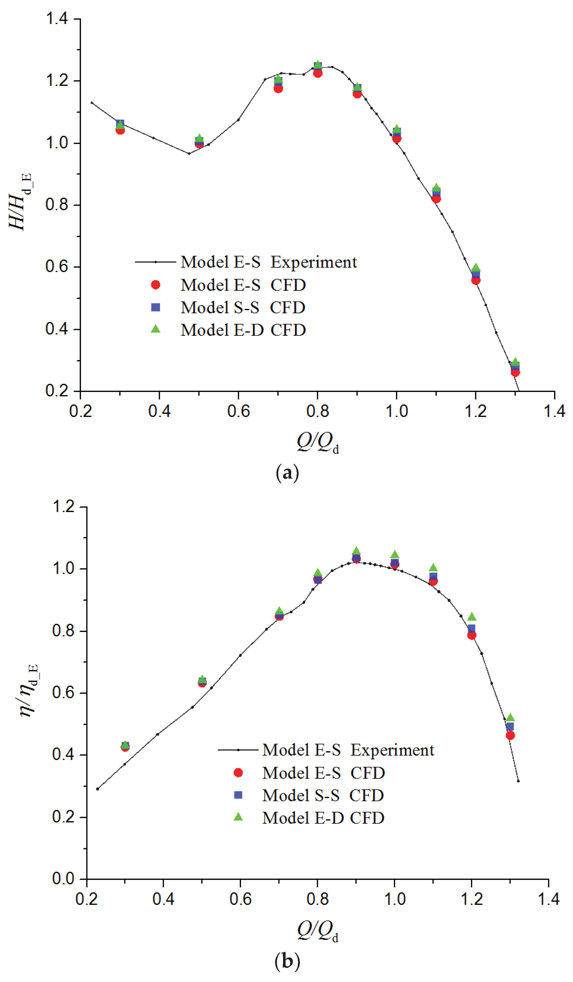
The hydraulic performance of Model E-S obtained by the CFD and experimental methods are shown and compared in Figure 9. The head and efficiency are calculated on basis of the stagnation pressure difference between the suction and discharge reference sections of pump (located at the impeller inlet and pump casing outlet, respectively), which is consistent in CFD and experimental methods. The measurement errors for head and efficiency are 0.102% and 0.219%, respectively, in experiment. Nine flow rates corresponding to 30%, 50%, 70%, 80% 90%, 100%, 110%, 120%, and 130% of the design flow rate are considered in the CFD method. The head and efficiency in Figure 9 are also expressed as the ratios to the corresponding experimental data of Model E-S at design flow rate. Overall, the CFD results of hydraulic performance are in good agreement with experimental data, especially around the design flow rate and at high flow rates. At the design flow rate, the relative CFD prediction errors for head and efficiency are 1.5% and 1.6%, respectively. Larger prediction error occurs in the part-load flow rate range (Q < Qd, i.e., 0.3Qd-0.9Qd). The head is underestimated in the hump region, while the efficiency is overestimated at minimal flow rates. These are mainly attributed to the limited capacity of the steady CFD calculation with the RANS turbulence model for predicting the complicated flow phenomena at part-load flow rate, such as the stall flow and separate flow. Nevertheless, in general, the accuracy of the CFD prediction for the hydraulic performance is acceptable within the concerned flow rate range. The CFD results of the hydraulic performance and the CFD method for steady calculation in this study are validated to be reliable.
The CFD results of the hydraulic performance shown in Figure 9 are all obtained by the steady calculations employing the aforementioned PiMo boundary conditions (BCs, for short) scheme. However, adopting the PiMo or MiPo BCs combination almost makes no difference on the steady calculation results. The calculation results under PiMo BCs and MiPo BCs would overlap with each other in the figure at each flow rate. For this reason, those under MiPo BCs are not given herein.
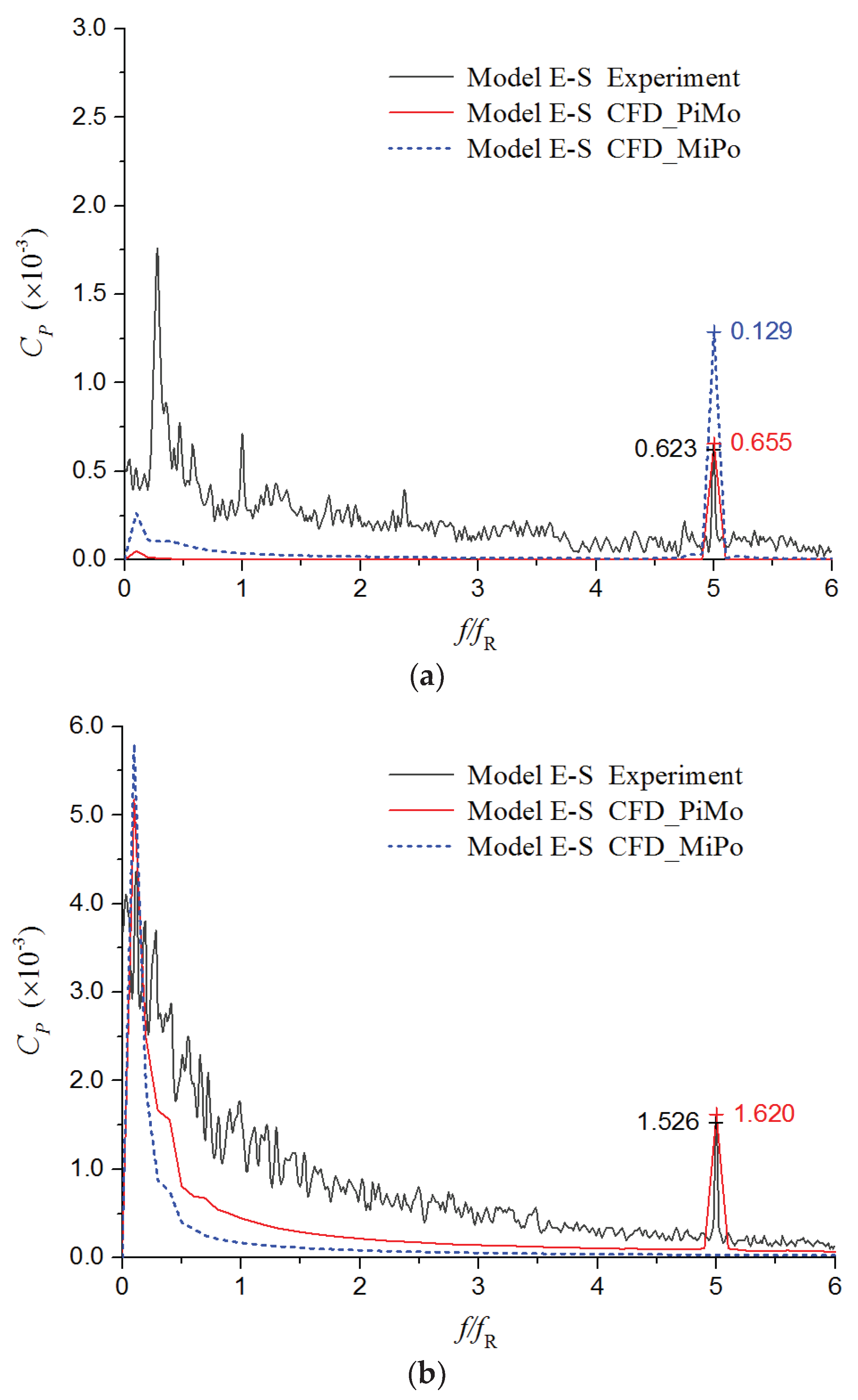
Moreover, in order to validate the unsteady CFD results, the spectra of the pulsating pressure at two measuring points (M1 and M2) obtained by the CFD and experimental methods are shown together in Figure 10. Furthermore, both the unsteady calculation results under PiMo BCs and MiPo BCs are presented herein. The frequency is expressed as the ratio to the impeller rotating frequency fR (20.83 Hz), and the amplitude is normalized to be the pressure coefficient CP:
C P = P 0.5 ρ u 2 m 2
where P is the pressure (Pa), ρ is the density of fluid (kg/m3), and u2m is the peripheral velocity at the mid-span of the impeller outlet (m/s).
As shown in Figure 10, for both measuring points, the CFD method employing the PiMo BCs scheme accurately predicts the pressure pulsation components at the blade passing frequency fBPF (5fR), which are related to the rotor-stator interaction (RSI). In contrast, the CFD method employing the MiPo BCs scheme grossly overestimates the pressure amplitude at fBPF for the suction measuring point M1 and entirely misses the component at 
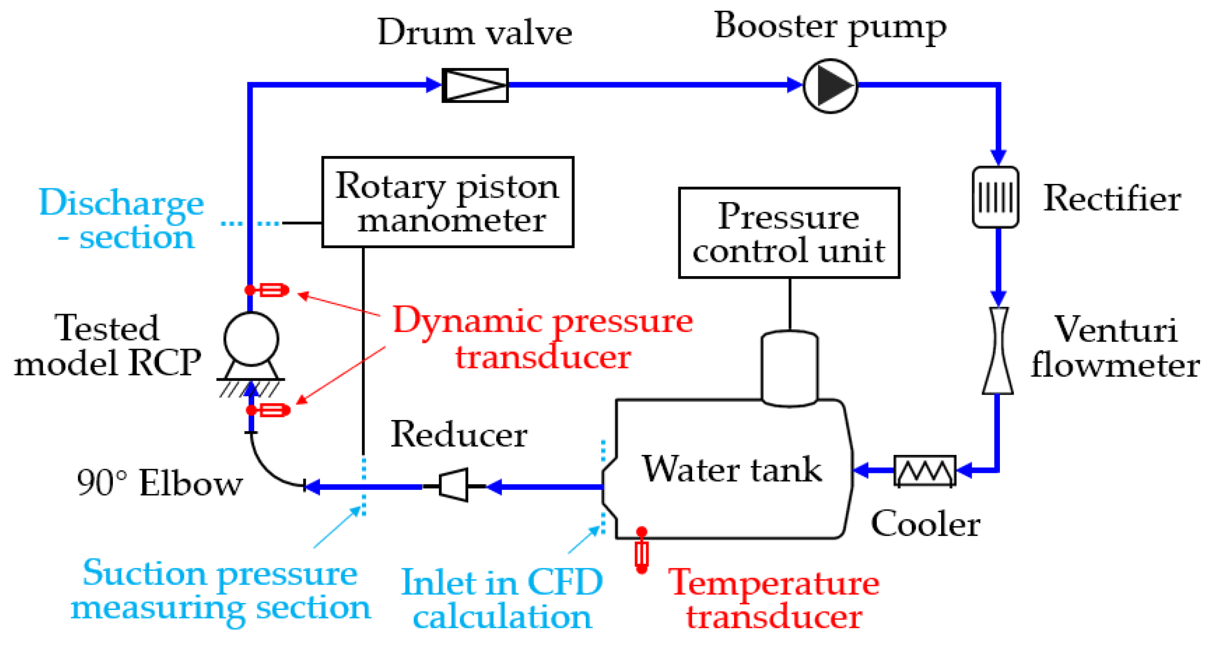
fBPF for the discharge measuring point M2. The reason for this is that, the water tank connected with pressure control unit is arranged on the suction side of pump in experiment, as shown in Figure 8. Consequently, setting constant pressure at the inlet as the PiMo BCs scheme is more reasonable and accordant with the actual situation in experiment. On the contrary, the false setting of the constant pressure outlet in the MiPo BCs scheme severely inhibits the pressure pulsation component at fBPF on the discharge side of pump. This inhibiting effect is even found in the pump casing and diffuser by further comparison. Meanwhile, the overlarge pressure amplitude at fBPF is motivated on the suction side of pump, without the actual constant pressure limit at the inlet.
Besides the components at fBPF, a mass of broadband low-frequency components (BLFCs, for short) also appear on the experimental pressure spectra, for both the measuring points. However, neither of CFD calculations under PiMo BCs and MiPo BCs accurately captures these pressure pulsation components. The BLFCs of pressure pulsation at the discharge measuring point M2 are mainly caused by the complex instable flow in the cylindrical casing which is discussed in the following section. For the instability of this chaotic flow, the realizable k-ε RANS model lacks the prediction capacity. The chaotic flow in pump casing, as well as the instable flow upstream of pump, also has a motivating effect on the BLFCs at the suction measuring point M1. Meanwhile, the chaotic instable flow also interacts with the boundary layer flow, which further makes the BLFCs of the pressure pulsation taken from the near-wall region in the experiment more complex and intense. Besides, the system instability of the test rig, unbalance of rotors due to inevitable manufacturing errors, and non-linear interactions between components are also considered to account for the BLFCs of the experimental pressure pulsation at points M1 and M2. These issues are all beyond the research capability of the CFD method used in the present paper.
Nevertheless, because the focus of this study is the unsteady flow phenomena related to the RSI (with frequencies as fBPF and the upper harmonics), the unsteady calculation results under PiMo BCs, which agree quite well with the experimental data for pressure pulsation components at fBPF, are considered acceptable. On the other side, because the measuring points are located relatively far away from the impeller, the pressure pulsation components at fBPF of them are severely attenuated. Actually, in the more crucial and concerned region around the impeller, the component at fBPF is overwhelmingly dominant for pressure pulsation and dynamic fluid force (see following sections). Hence, the following unsteady study on the basis of the CFD calculation results under PiMo BCs is reasonable.

5.2. Hydraulic Performance

By the steady CFD calculations employing PiMo BCs combination, the hydraulic performance of the three RCP models with different suction and discharge configurations is obtained, as shown in Figure 9. The head curves and the efficiency curves of the three models all have the same shape. A conspicuous section with the positive slope appears in the flow rate range between 50%Qd and 80%Qd on the head curve. From the efficiency curves, the best efficiency point is located at the flow rate of 90%Qd, and high efficiency was achieved from 80%Qd to 110%Qd.
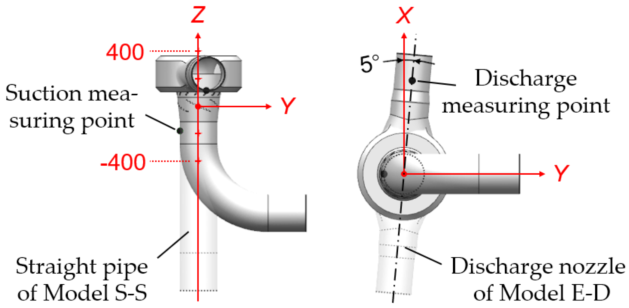
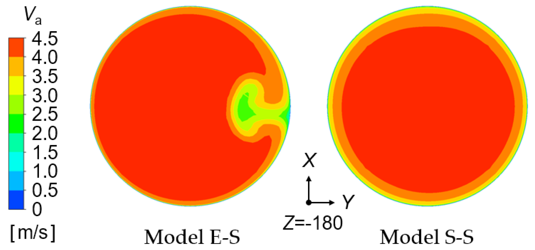
Comparing the performance of Model E-S and Model S-S, which have the different suction configurations, the head of Model S-S (with straight suction pipe) is higher in the whole flow rate range than that of Model E-S (with an elbow on the suction side), and the efficiency of Model S-S is also higher than that of Model E-S at the overload flow rate. In the part-load flow rate range, Model S-S and Model E-S have nearly the same efficiency. In detail, at the design flow rate, the head and efficiency of Model S-S are, respectively, 2.0% and 0.5% higher than those of Model E-S. These differences in hydraulic performance between Model E-S and Model S-S mainly result from their different suction flow conditions. The axial velocity distribution on the suction flow section 0.4DS upstream of impeller inlet (between the impeller and elbow for Model E-S) is shown in Figure 11. After passing through the elbow, the suction flow of Model E-S becomes obviously asymmetric in the circumferential direction. A distinct flow region with low axial velocity is formed on the side in Y direction of section center (the small-curvature side of elbow). Meanwhile, due to the existence of the distinct low-axial-velocity region, the near-wall low-velocity area of Model E-S is reduced overall, compared with that of Model S-S. Both the asymmetric axial velocity distribution and near-wall low-velocity area reduction of suction flow are detrimental to the work performing of impeller. (Existence of the near-wall low-velocity area could concentrate more flow into the main flow region of impeller instead of the tip leakage region.) Consequently, Model E-S gets the lower head. With respect to the efficiency, because the power and head of pump almost vary by the same proportion, the efficiency of these two models is nearly equivalent in the partial flow rate range. Specially, at the overload flow rate, with the rise of pump head, the flow circulation at the impeller outlet increases and the flow angles in the diffuser and casing return to be more suitable. Consequently, Model S-S with the higher head also achieves a higher efficiency at overload flow rates.
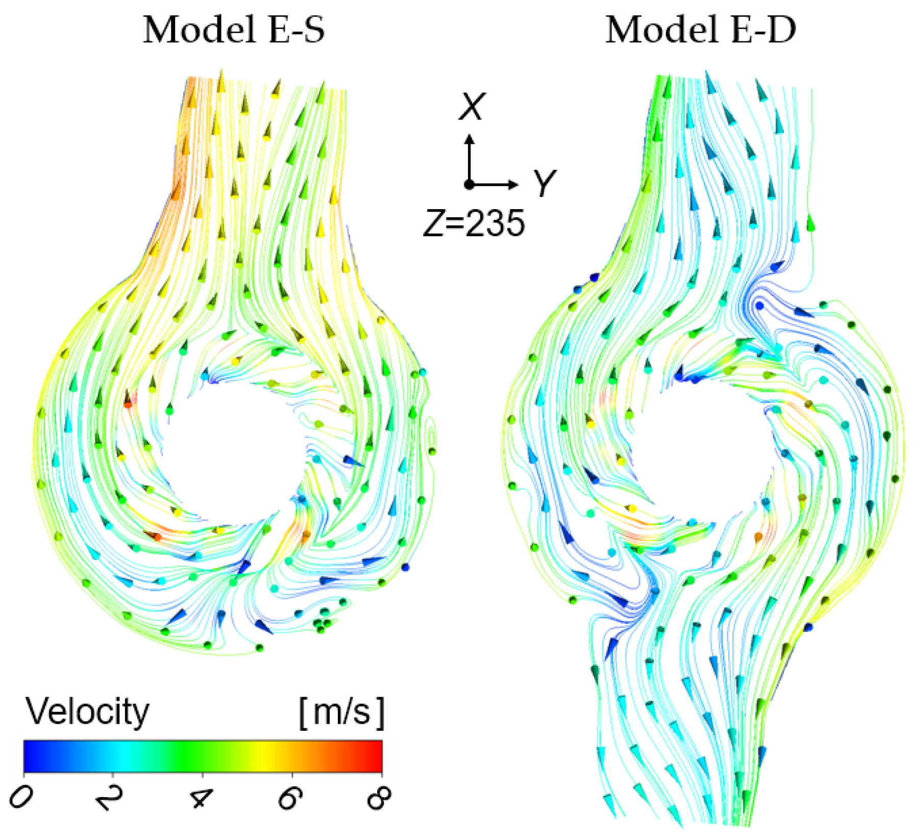
When it comes to the comparison of Model E-S and Model E-D with the different discharge configurations, in the whole flow rate range, Model E-D with the double-discharge casing achieves both the higher head and higher efficiency than Model E-S with the single-discharge casing. Furthermore, with the increase of flow rate, Model E-D gains more advantages in the head and efficiency. In detail, at the design flow rate, the head and efficiency of Model E-D is, respectively, 2.7% and 2.8% higher than those of Model E-S. The pump power of Model E-S and Model E-D is roughly the same in the whole flow rate range. The differences in head and efficiency between them are mainly due to the flow pattern change and consequent loss variation in pump casing. The flow conditions in the two pump casings are revealed in Figure 12, by means of the streamlines and velocity distribution on the middle axial section. The arrows indicate the flow direction and the color of streamline represents the magnitude of velocity. As shown, the axial flow from diffuser turns radial in the cylindrical casing. The flow rushes toward the discharge nozzle through the internal annular flow passage, actually with unceasing rolling inside as well. Due to the difference in the discharge nozzle number, different flow patterns are formed in the two casing. By comparison, due to the addition of another discharge nozzle, the flow distance in the double-discharge casing is reduced overall. Meanwhile, compared with that in the single-discharge casing, the total flow passage area in the double-discharge casing increases, which results in a significant decrease in the internal flow velocity, especially in the region near the discharge nozzle. Both the flow distance reduction and flow velocity decrease in the double-discharge casing are beneficial to the loss reduction. Consequently, compared with Model E-S, Model E-D achieves a higher head and efficiency. Additionally, since the relationship between the loss in casing and the flow rate is approximately quadratic, the head and efficiency differences between Model E-D and Model E-S also increase with the flow rate.

5.3. Pressure Pulsation in Rotating Frame

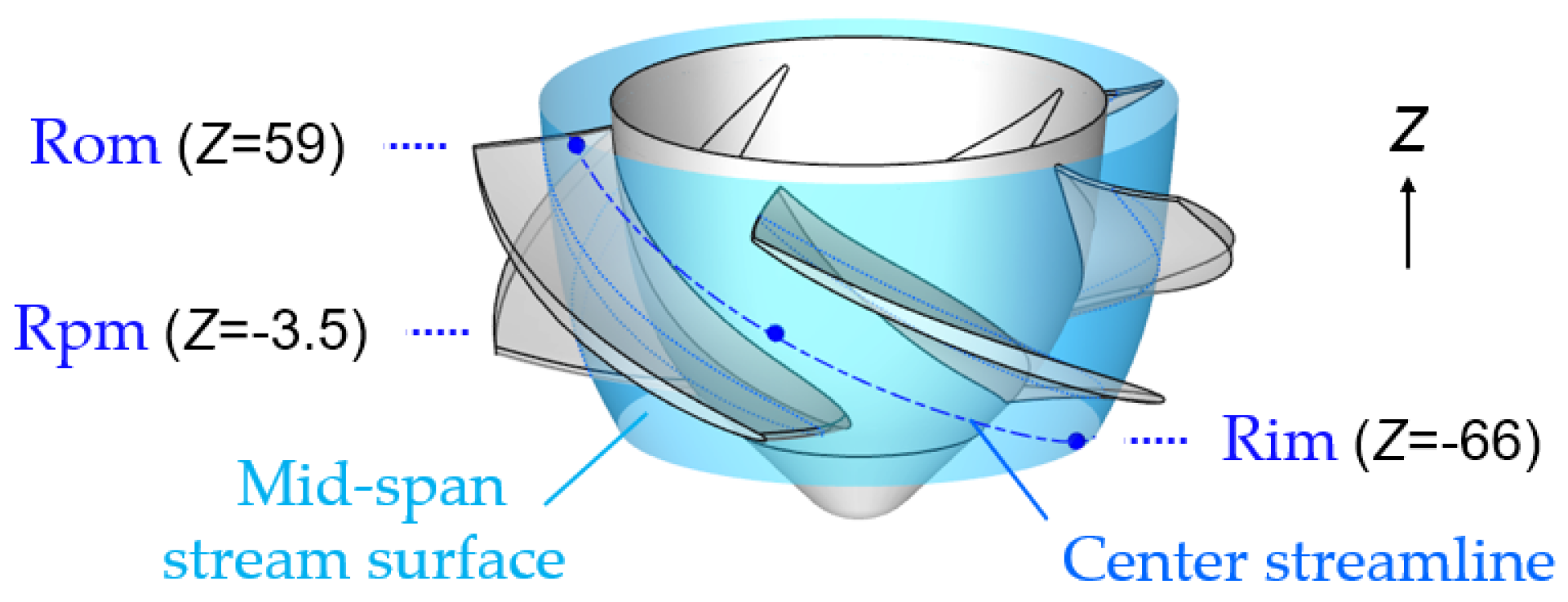
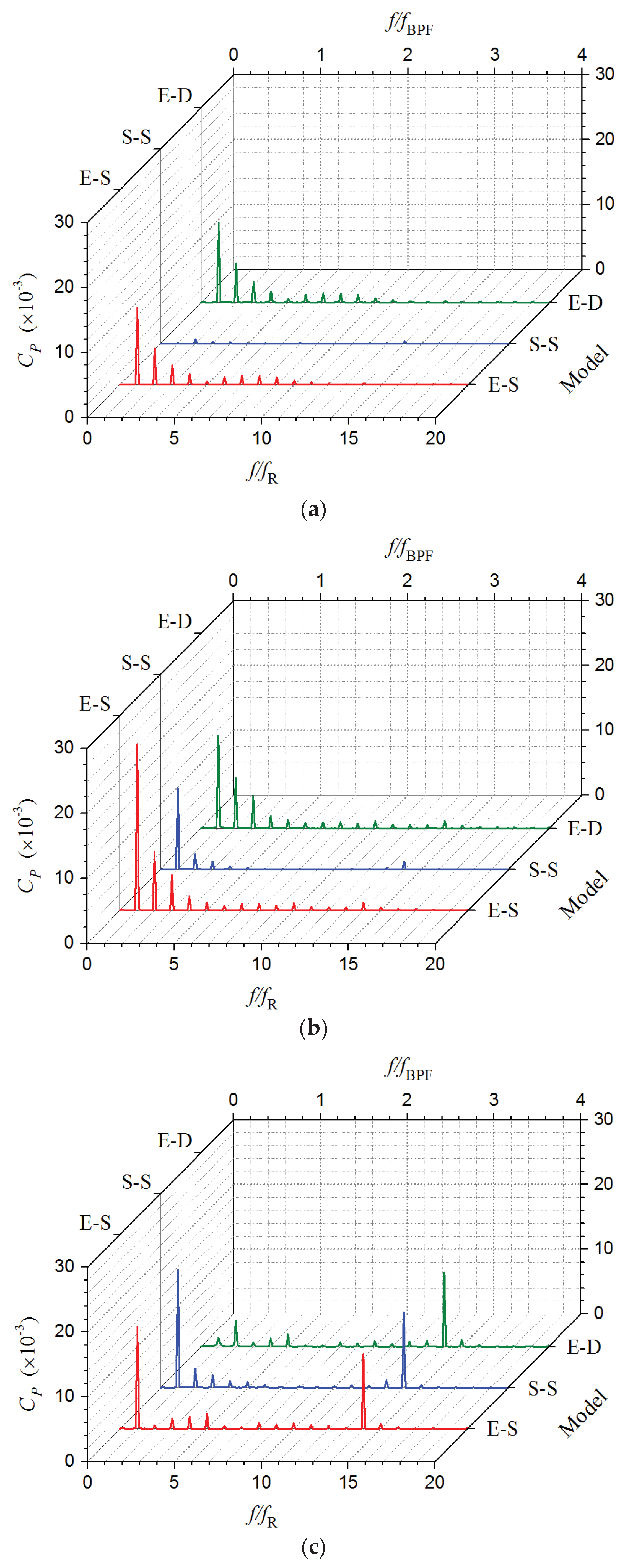
For the three RCP models, the spectra of the pulsating pressure at the three monitoring points in rotating frame are compared in Figure 13. The frequency is expressed as the ratios to the impeller rotating frequency fR and blade passing frequency fBPF, and the amplitude is normalized as the pressure coefficient CP. As shown, for the pressure spectra of rotating Point Rim at the impeller inlet, those of Model E-S and Model E-D (with the same suction elbow) are almost the same. The pressure pulsation components at 
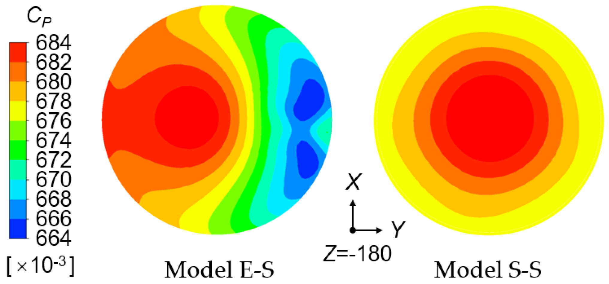
fR and the harmonic frequencies of them are both obvious. In contrast, no obvious peak is observed on the pressure spectrum of Model S-S (with straight suction pipe) herein. The reason for this could be explained by the pressure distribution on the suction flow section 0.4DS upstream of the impeller inlet. As shown in Figure 14, downstream of the elbow, the pressure distribution on the suction flow section of Model E-S (as well as Model E-D) becomes obviously asymmetric in the circumferential direction. Overall, the pressure there gradually decreases along the positive Y direction. A low-pressure region is formed on the side in positive Y direction of section center (the small-curvature side of elbow), while high pressure appears on the opposite side. Furthermore, in the impeller inlet region, this asymmetric pressure distribution in fixed frame still exists. Consequently, for Model E-S and Model E-D, the point in rotating frame close to the impeller inlet, such as Point Rim, would pass through a low-pressure region and then a high-pressure region overall in a rotational cycle. As a result, the pressure pulsation at Point Rim of them is dominated by the component at fR. Furthermore, due to the irregularity of pressure fluctuation, upper harmonic components also arise. Conversely, for Model S-S, the pressure distribution on the suction flow section is roughly uniform in the circumferential direction. Therefore, no obvious pressure pulsation in rotating frame is generated in the impeller inlet region of Model S-S.
With regard to the pressure spectra of Point Rom at the impeller outlet, those of Model E-S and Model S-S (both employing the single-discharge casing) are roughly the same, which are dominated by components at fR and 14fR. However, on the pressure spectrum of Model E-D, only the same spike at 14
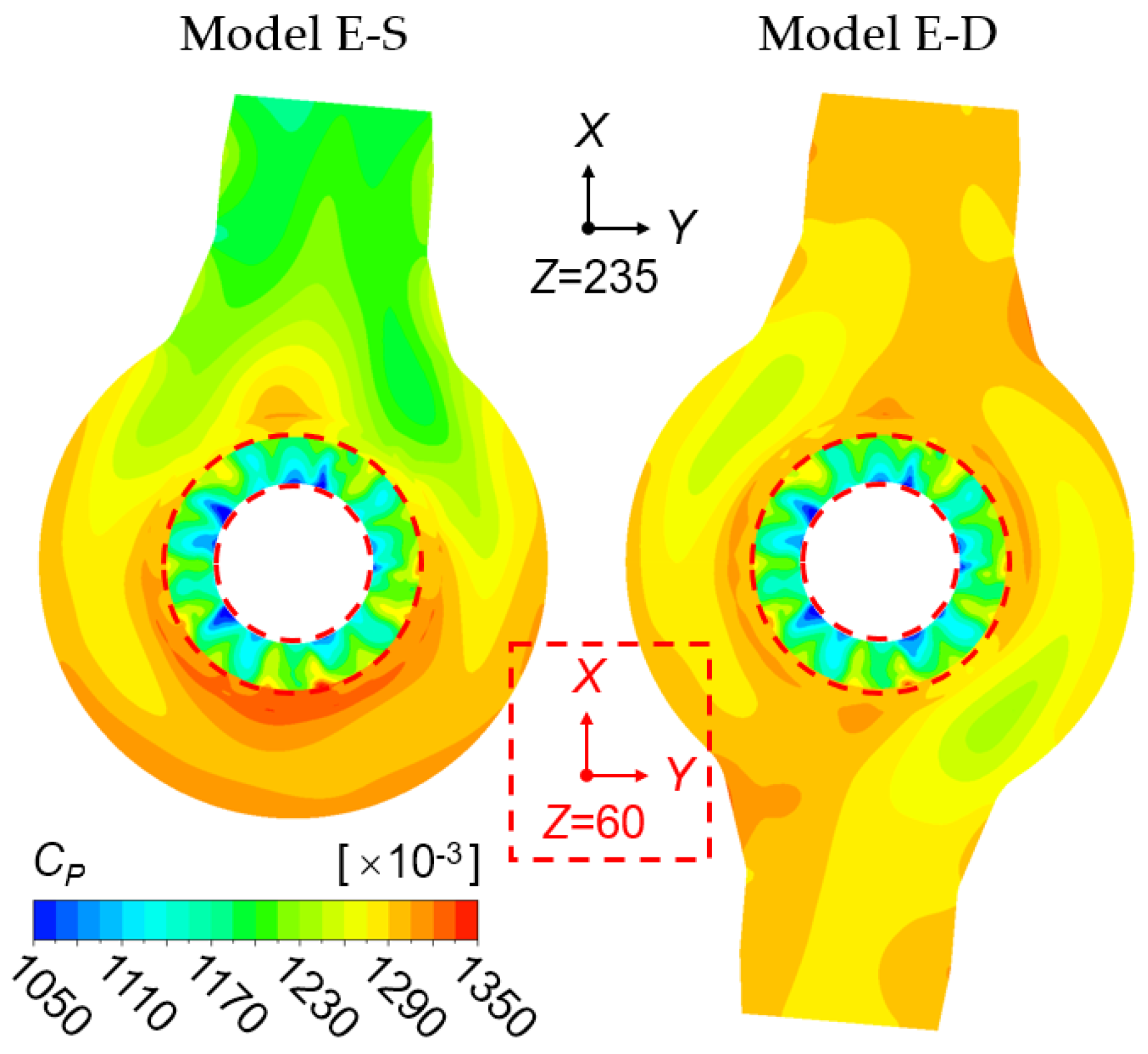
fR is observed. The component at fR of it almost disappears. In order to reveal the reasons, for Model E-S and Model E-D, the pressure contours at the impeller outlet (within red dashed circular rings) and those on the middle axial section of pump casing are stacked together and shown in Figure 15. Firstly, due to the impact of diffuser, for both models, 14 pairs of alternately distributed high-pressure and low-pressure regions in the circumferential direction are observed at the impeller outlet. It is exactly this pressure distribution in the fixed frame that causes the pressure pulsation component at 14fR in the rotating frame close to the impeller outlet. Besides the impact of diffuser, the pressure distribution at the impeller outlet is also affected by the flow condition downstream in the pump casing. In the single-discharge casing, the pressure distribution is quite uneven in the circumferential direction. Low pressure appears in the discharge nozzle region, while high pressure appears on the opposite side. Furthermore, with a certain deflection in the counter-clockwise direction due to the circumferential motion of the flow downstream of impeller, this asymmetric bipolar-opposite distribution of pressure (which has a high-pressure region on one side and a low-pressure region on the opposite side) also appears at the impeller outlet. As a result, for Model E-S and Model S-S, the component at fR of the pressure pulsation in rotating frame is motivated in the region close to the impeller outlet. Moreover, because the pressure distribution at the impeller outlet is relatively regular, the harmonics at 2fR~4fR of Point Rom are not as remarkable as those of Point Rim. By contrast, in the double-discharge casing, due to the symmetry of the structure, the pressure distribution is roughly symmetric and visibly more uniform. Accordingly, the pressure distribution at the impeller outlet of Model E-D is also relatively symmetric. Consequently, no obvious pressure pulsation component at fR arises at Point Rom which is set in the rotating frame and close to impeller outlet. In addition, for Model E-D, the double-discharge pump casing also stimulates the pressure pulsation component at 2fR to some extent.
Within the flow passage of impeller, both the flow patterns upstream and downstream of the impeller have effects on the pressure pulsation in rotating frame. For Model E-D, the pressure pulsation at Point Rpm is mainly motivated by the asymmetric suction flow related to the elbow, as that at Point Rim. Consequently, the pressure spectrum of Model E-D at Point Rpm is similar to that at Point Rim. Furthermore, the effect of the asymmetric suction flow is greater at Point Rpm than that at Point Rim. Hence, the pressure pulsation amplitudes at fR~3fR (which are related to the irregular asymmetric suction flow, as stated previously) of Point Rpm are larger than those of Point Rim. In contrast, for Model S-S, the pressure pulsation at Point Rpm is mainly motivated by the asymmetric flow downstream of impeller related to the single-discharge casing. Consequently, the pressure spectrum of Model S-S at Point Rpm is similar to that at Point Rom apart from 14fR. Furthermore, the effect of the downstream asymmetric flow is weakened at Point Rpm, compared with that at Point Rom. Hence, the pressure pulsation amplitude at fR (which are related to the downstream asymmetric flow) of Point Rpm is smaller than that of Point Rom. For Model E-S, both the asymmetric suction flow and asymmetric flow downstream of impeller have motivating effects on the pressure pulsation at Point Rpm. Furthermore, because the phase difference between the asymmetric pressure distribution at the impeller inlet and outlet is just close to the blade wrap angle, the pressure pulsation component at fR of Model E-S is greatly enhanced at Point Rpm. Besides, within the flow passage of impeller, the effect of diffuser on the pressure pulsation in rotating frame is severely weakened. Thus, unlike those of Point Rom, no obvious component at 14fR was observed on the spectra of Point Rpm.
Overall, for the axial-flow RCP, the variation of the suction and discharge configurations greatly affects the pressure pulsation in rotating frame. As stated above, all the circumferentially non-uniform flow patterns related to the stationary components upstream and downstream would motivate the corresponding components of pressure pulsation in the rotating frame of impeller. Compared with the suction pipe with elbow and the single-discharge casing, respectively, the straight suction pipe of Model S-S and the double-discharge casing of Model E-D result in more uniform flow upstream and downstream of impeller. Consequently, the pressure pulsation in the rotating frame of Model S-S and Model E-D is reduced overall in the impeller region, compared with that of Model E-S. The pressure pulsation in rotating frame actually reveals and evaluates the impacts of stationary components on the rotating impeller region which are the one aspect of RSI. The above results show that, for the axial-flow RCP, the unsteady flow field in the rotating frame around impeller is affected by all the stationary components, not only the diffuser but also the suction elbow and cylindrical pump casing. The RSI, which plays a significant role in the unsteady flow phenomena, exists not only between the impeller (rotor) and diffuser (stator). In fact, the generalized RSI exists between the rotating impeller and all stationary components that cause circumferentially non-uniform flow. Or rather, the RSI is actually the interaction between the rotating circumferentially non-uniform flow field of impeller and the fixed one related to the stationary components. The results also indicate that, the straight suction pipe of Model S-S and the double-discharge casing of Model E-D, which respectively make the flow fields upstream and downstream more uniform in the circumferential direction, have less interference to the rotating flow field of impeller. Consequently, compared with that in Model E-S, the RSIs in Model S-S and Model E-D are weakened in different degrees. Improving the circumferential uniformity of flow fields upstream and downstream of the impeller region contributes to the reduction of RSI in the axial-flow RCP.

5.4. Pressure Pulsation in Fixed Frame

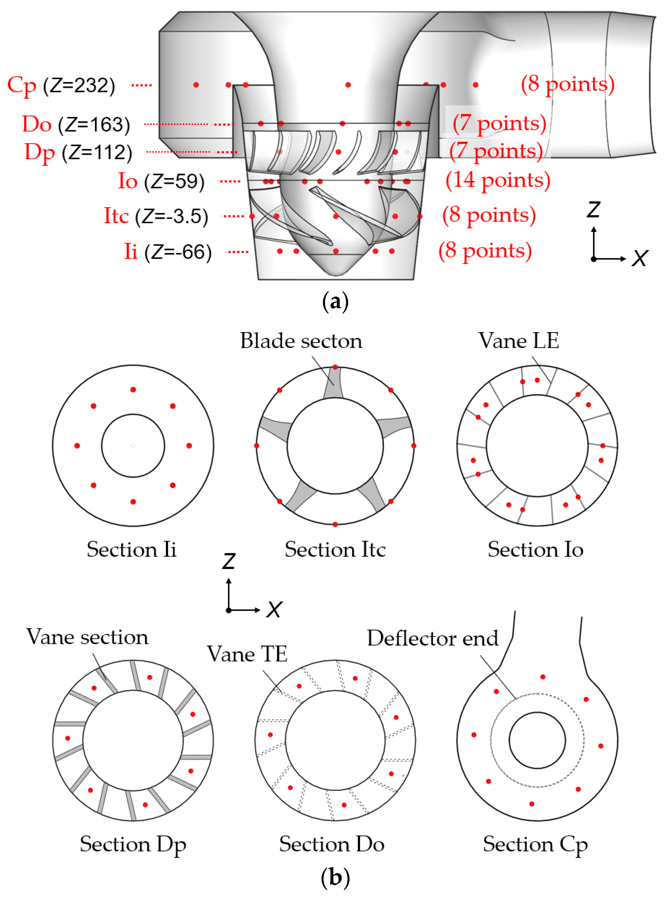
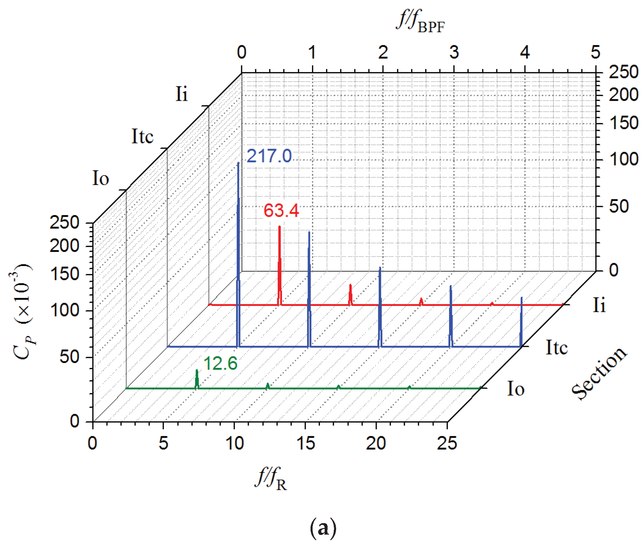
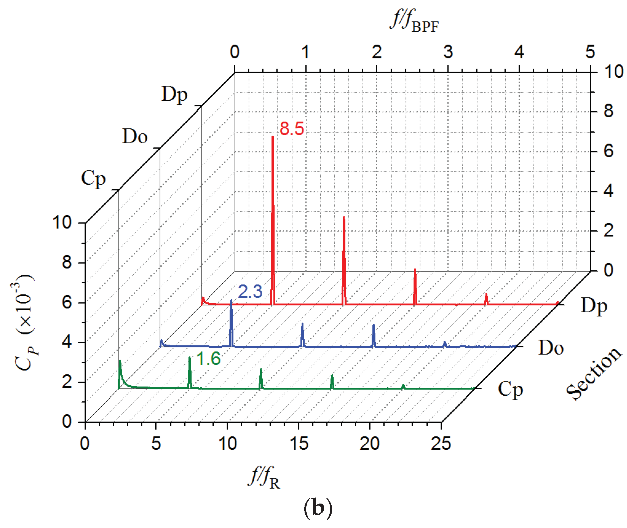
In order to get an overall view of the pressure pulsation in the fixed frame, the pressure spectra of fixed monitoring points are averaged on each axial section (see Figure 6). As an example, the obtained average pressure spectra of Model E-S on the six sections are shown in Figure 16. As shown, the pressure spectra are all dominated by components at the blade passing frequency fBPF (5fR) and its harmonic frequencies. Because the pressure pulsation in fixed frame is mainly caused by the rotating of the impeller with 5 equispaced blades and uneven flow field around. The pressure pulsation (of monitoring points in the blade tip clearance) on Section Itc in the middle of impeller (main exciting source) is the strongest of all, which is related to the huge pressure difference between the blade tip gap and flow passage of impeller. Moreover, due to the complex flow condition in the tip leakage region, the amplitudes of harmonics at 2fBPF~5fBPF on Section Itc are still quite large (unlike those on the other sections). From here on, the pressure pulsation components at fBPF and upper harmonic frequencies gradually attenuate upstream and downstream. The pressure pulsation on Section Ii at the impeller inlet is still very strong, of which the average amplitude at fBPF is about 30% of that on Section Itc. Whereas, on Section Io at the impeller outlet, the pressure pulsation is severely weakened, compared with that at the impeller inlet. The average pressure pulsation amplitude at fBPF of Section Io is only about one fifth of that of Section Ii. Entering the flow passage of diffuser, the pressure pulsation on Section Dp is further weakened. Then, after passing through the diffuser, the pressure pulsation components at fBPF and the harmonic frequencies become comparatively rather week. The average amplitudes at fBPF of Section Do and Section Cp are approximately two orders of magnitude lower than that of Section Itc in the middle of impeller.
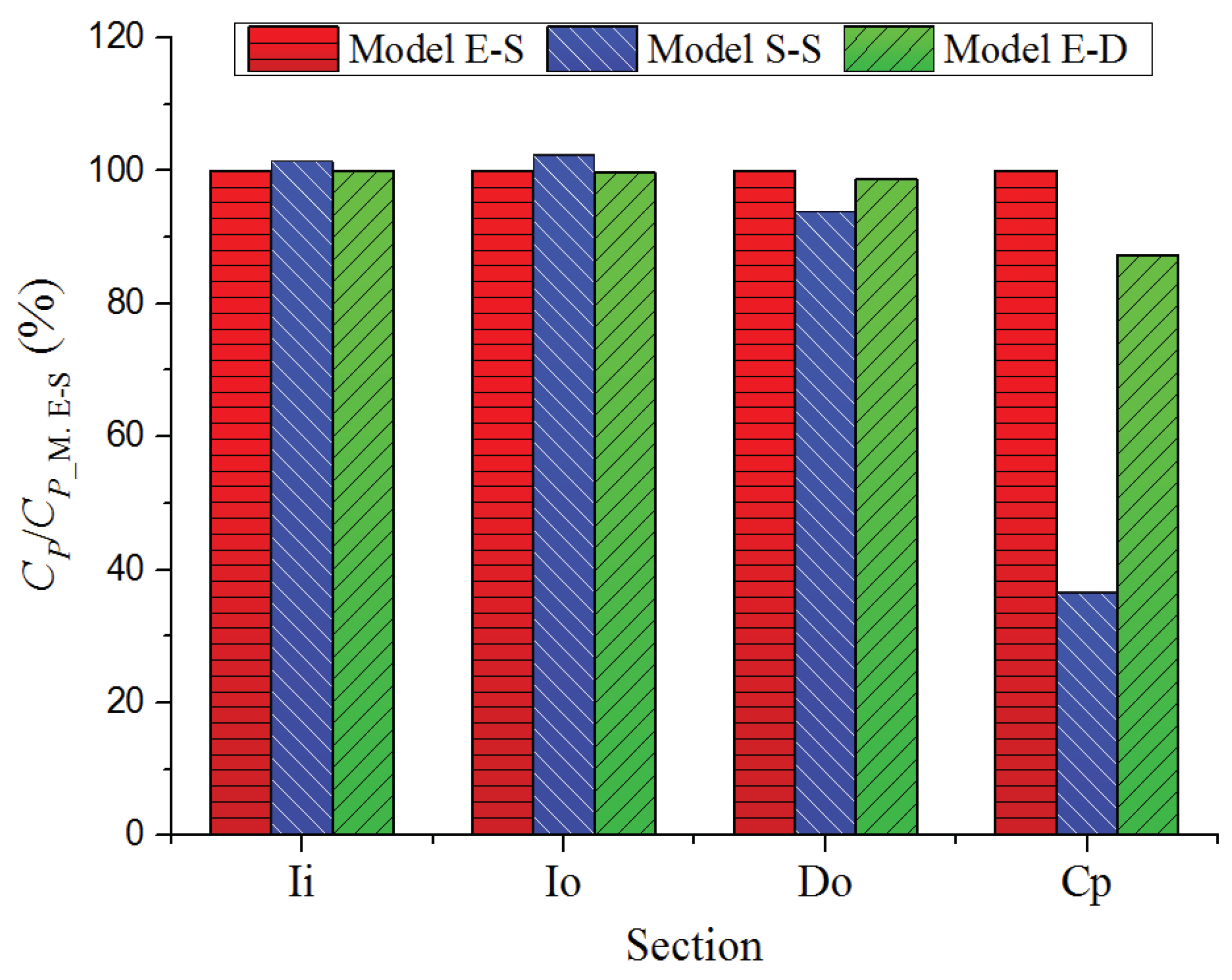
Moreover, in order to investigate the effects of suction and discharge conditions on the pressure pulsation, the average pressure pulsation amplitudes at fBPF on each section of the three RCP models are compared in Figure 17. For ease of comparison, on each section, the average pressure pulsation amplitudes are expressed as the Relative CP, which is the ratio of CP to that of Model E-S. As shown in Figure 17, on Section Ii and Section Io near the impeller, the pressure pulsation amplitudes at fBPF of the three models are without much difference. This is because, in the region close to impeller, the pressure pulsation in the fixed frame is directly affected by the rotating impeller, which is exactly unmodified in this study for the three models. Distinctively, the pressure pulsation amplitudes at fBPF of Model S-S is slightly higher on Section Ii and Section Io. The reason for this is that, the uniform suction flow of Model S-S makes the flow distribution in the 5 flow passages of impeller more accordant, which thereby enhances the pressure pulsation component at fBPF to a small extent. In contrast, on Section Do and Section Cp, compared with those of Model E-S, the pressure pulsation amplitudes at fBPF of Model S-S and Model E-D become obviously smaller, especially for those of Model S-S and those on Section Cp which is comparatively far away from the impeller. On Section Cp, the average amplitudes at fBPF of Model S-S and Model E-D are 36.5% and 87.3% of that of Model E-S, respectively. The pressure pulsation in fixed frame reflects the other aspect of the RSI, i.e., the impact of rotating impeller on the stationary flow field. Thus, this difference considered to be related to the weakened RSI between the impeller and straight suction pipe in Model S-S, as well as that (the weakened RSI) between the impeller and double-discharge casing in Model E-D. Nevertheless, the absolute difference of pressure pulsation amplitude among the three models on Section Do and Section Cp is actually not large, because the pressure pulsation is quite weak there, as that of Model E-S shown in Figure 16. Hence, for the axial-flow RCP, the variations of suction and discharge conditions studied in this article overall have no significant effect on the pressure pulsation in fixed frame.

5.5. Dynamic Fluid Force

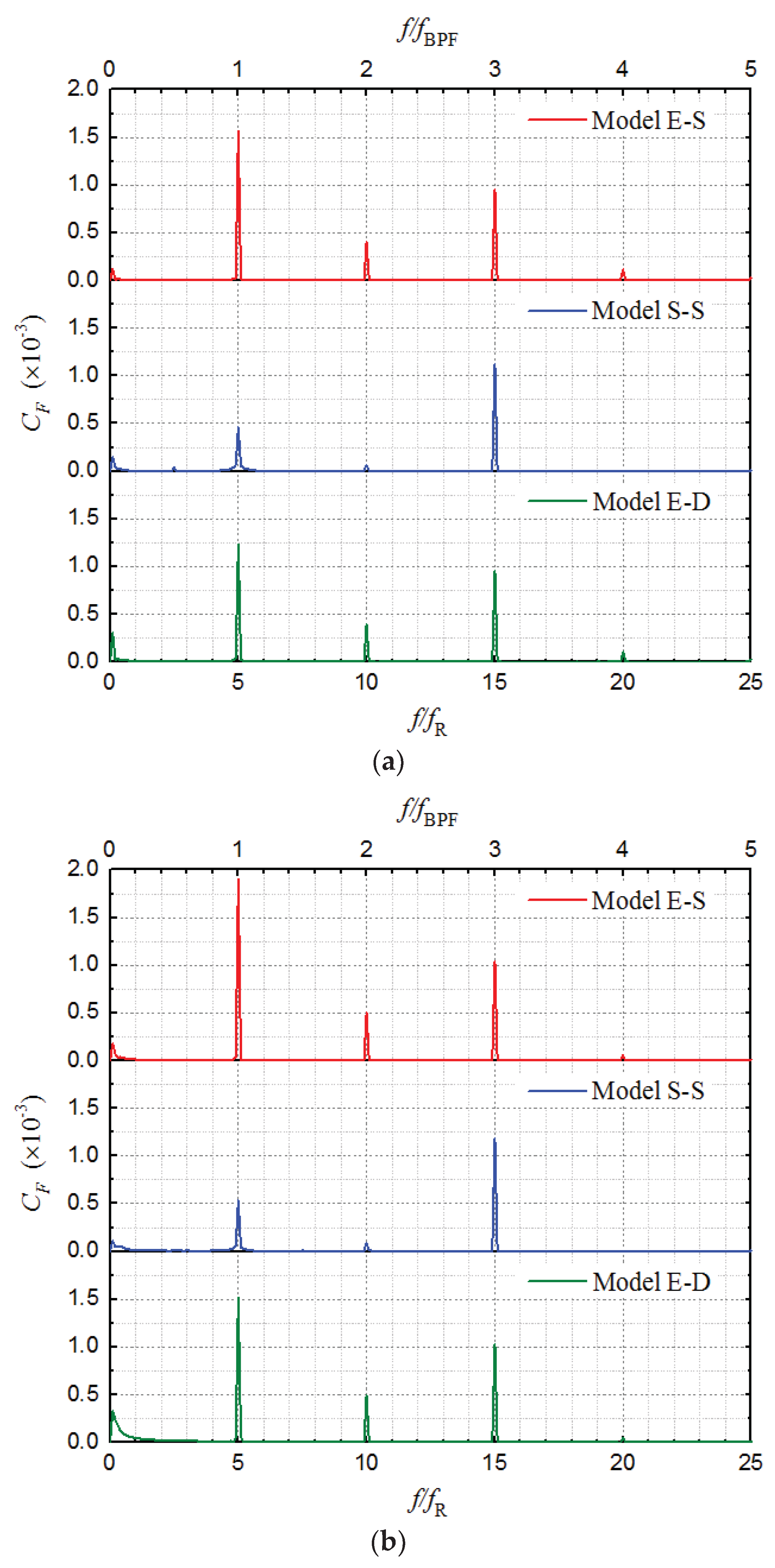
The dynamic fluid force is another important unsteady flow phenomenon, which plays a more direct role in the vibration and noise inducing of pump. Among the dynamic fluid forces, those radially acting on the impeller are particularly significant and critical. Herein, for the three RCP models with different suction and discharge configurations, the spectra of the radial dynamic fluid forces acting on impeller are obtained and compared in Figure 18. The direction of forces is defined in accordance with the coordinate system specified in Figure 5, and the amplitude is normalized as the force coefficient CF:
C F = F 0.5 ρ u 2 m 2 × π D 2 m b 2
where F is the force (N), D2m is the diameter at the mid-span of impeller outlet (m), and b2 is the width of impeller outlet (m).
As shown in Figure 18, the components of radial dynamic fluid forces are mainly at fBPF, 2fBPF, and 3fBPF on every spectrum. The force amplitudes at 3fBPF of the three models are basically the same (merely those of Model S-S are slightly larger). The difference among the three models is mainly in the components at fBPF and 2fBPF. For the force amplitudes at fBPF and 2fBPF, those of Model E-S are the largest of all. Compared with those of Model E-S, the amplitudes of Model S-S significantly decrease at both fBPF and 2fBPF. The force amplitudes at fBPF of Model S-S are only 29.1% and 27.9% of those of Model E-S in the X and Y directions, respectively. The force amplitudes at fBPF of Model E-D also decrease to some extent, compared with those of Model E-S. The force amplitudes at fBPF of Model E-D are respectively 78.0% and 79.6% of those of Model E-S in the X and Y directions. The force amplitudes of Model E-D are nearly equal to those of Model E-S at 2fBPF. Additionally, there is no significant difference between the spectra of FX and FY. For each model, the amplitudes at fBPF, 2fBPF, and 3fBPF of FY are just a little higher than those of FX.
From the results stated above, for the axial-flow RCP, the suction and discharge conditions also have significant effects on the radial dynamic fluid forces acting on impeller. The reason for this is considered to be related to the variation of the RSI (which would cause dynamic fluid forces with frequencies as fBPF and the upper harmonics). As concluded in Section 5.3, the RSI actually exists between the rotating impeller and all stationary components that cause flow to be non-uniform in circumferential direction. The RSI is basically the interaction between the rotating circumferentially non-uniform flow flied around the impeller and the fixed one related to the stationary components. The strength of the RSI is greatly affected by the circumferential uniformity of the flow fields upstream and downstream of impeller in the fixed frame. The straight suction pipe of Model S-S and the double-discharge casing of Model E-D bring more uniform flow fields and proved to have less interference to the rotating flow field of impeller. Consequently, compared with that in Model E-S, the RSIs in Model S-S and Model E-D are weakened. The radial dynamic fluid forces acting on impeller are mainly induced by the RSI. The weakening of RSI leads to the reduction of radial dynamic fluid forces. As a result, compared with those of Model E-S, the amplitudes of the radial dynamic fluid forces acting on impeller of Model S-S and Model E-D decrease at fBPF and 2fBPF in different degrees. Furthermore, because the suction flow of Model S-S is almost completely uniform in the circumferential direction, its amplitudes of the dynamic FX and FY at fBPF and 2fBPF become quite small. By contrast, the change of RCP casing from single-discharge to double-discharge just partially improves the circumferential uniformity of the flow field downstream of impeller. Consequently, the dynamic FX and FY of Model E-D only gain a minor amplitude decrease at fBPF, compared with those of Model E-S. In addition, the further investigation indicates that, the component of radial dynamic fluid forces at 3fBPF is mainly caused by the resonance between the impeller and diffuser. Furthermore, as mentioned previously, because the suction flow of Model S-S is almost uniform, its flow distribution in the 5 flow passages of impeller is more accordant. Therefore, the resonance between the impeller and diffuser of it is exacerbated to a small extent. This is the reason why the components of Model S-S slightly increase at 3fBPF, compared with those of the other two models.

6. Conclusions

In this study, three axial-flow RCP models with different suction and discharge configurations are investigated by the CFD method.
The CFD results are validated by the experimental data. The steady CFD method accurately predicts the hydraulic performance of RCP. As for the prediction of pressure pulsation, the accuracy is greatly affected by the setting of inlet and outlet boundary conditions. The unsteady CFD method adopting the PiMo (pressure inlet and mass flow rate outlet) BCs which is more accordant with the actual situation in experiment, accurately predicts the pressure pulsation component at the blade passing frequency. However, for the broadband low-frequency components of pressure pulsation, which are complex but secondary, the CFD method employing the realizable k-ε model has certain limitations in accurate prediction.
The hydraulic performance of the three RCP models shows no significant difference. The head of Model S-S with straight suction pipe is slightly higher than that of Model E-S with an elbow on the suction side, because the non-uniform suction flow resulting from the elbow is detrimental to the work performing of the impeller. On the other side, because the double-discharge pump casing is beneficial to the internal loss reduction, Model E-D achieves both the higher head and higher efficiency than Model E-S with the single-discharge casing, especially at large flow rates.
For the axial-flow RCP, the pressure pulsation in the rotating frame is greatly affected by the variation of suction and discharge configurations. Compared with that of Model E-S, the pressure pulsation in the rotating frame of Model S-S and Model E-D is weakened overall in the impeller region. All the circumferentially non-uniform flow patterns upstream and downstream caused by the stationary components would motivate corresponding components of pressure pulsation in the rotating frame of impeller.
The pressure pulsation in rotating frame reveals and evaluates the impacts of stationary components on the rotating impeller region. For the axial-flow RCP, not only the diffuser (stator), but also the suction elbow and cylindrical pump casing, have interference to the rotating flow field of impeller. The RSI actually exists between the rotating impeller and all stationary components that cause non-uniform flow in the circumferential direction. The strength of RSI is greatly affected by the circumferential uniformity of the flow fields upstream and downstream of impeller in the fixed frame. Compared with that in Model E-S, the RSIs in Model S-S and Model E-D are weakened in different degrees. Improving the circumferential uniformity of flow fields upstream and downstream of impeller leads to reduction of the RSI in the axial-flow RCP.
With regard to the pressure pulsation in fixed frame, it is extremely strong in the impeller region and gradually attenuates upstream and downstream. The pressure pulsation in fixed frame is mainly related to the rotating impeller with uneven flow field around. The variations of suction and discharge conditions studied in this article have no significant effect on it, especially in the region close to impeller.
The suction and discharge conditions also have effects on the radial dynamic fluid forces acting on impeller. Compared with those of Model E-S, the dynamic FX and FY of Model S-S are severely weakened, and those of Model E-D also gain a certain amplitude decrease at fBPF. The reason for this is related to the variation of RSI. The weakening of RSI eventually leads to the reduction of radial dynamic fluid force. Therefore, improving the circumferential uniformity of the flow upstream and downstream of impeller also contributes to reducing the dynamic fluid force acting on impeller.

Author Contributions

Conceptualization, X.C. and D.W.; methodology, X.C., S.L. and P.W.; validation, D.W. and S.Y.; formal analysis, X.C. and S.Y.; investigation, X.C., S.L. and P.W.; resources, D.W.; data curation, X.C., D.W. and S.Y.; writing—original draft preparation, X.C. and S.L.; writing—review and editing, X.C., S.Y. and D.W.; visualization, X.C.; supervision, S.Y. and D.W.; project administration, S.Y. and D.W.; funding acquisition, S.Y. All authors have read and agreed to the published version of the manuscript.

Funding

This research was funded by National Natural Science Foundation of China, grant number 51706199, and Lab of Advanced Space Propulsion, grant number LabASP-2018-01.

Acknowledgments

This research was supported by HPC Center of Zhejiang University (Zhoushan Campus).

Conflicts of Interest

The authors declare no conflict of interest.

Nomenclature

CFforce coefficient
CPpressure coefficient
DSdiameter of suction pipe, mm
D2mdiameter at the mid-span of impeller outlet, mm/m
Fforce, N
FX, FYradial dynamic fluid force acting on impeller in the X, Y direction, N
Hhead, m
Ppressure, Pa
Qflow rate, m3/s
REturning radius of the suction elbow, mm
Vaaxial velocity, m/s
X, Y, Zx, y, z direction
ZBnumber of impeller blades
ZVnumber of diffuser vanes
b2width of impeller outlet, mm/m
ctip clearance size, mm
ffrequency, Hz
fRimpeller rotating frequency, Hz
fBPFblade passing frequency, Hz
ggravity acceleration, m/s2
nrotation speed, r/min
nsspecific speed
u2mperipheral velocity at the mid-span of impeller outlet, m/s
Δt time-step size in unsteady CFD calculation, s
Φflow rate coefficient
Ψhead coefficient
ηpump efficiency
ρdensity of fluid, kg/m3
Subscript
dparameter at design flow rate
E experimental parameter
M. E-S parameter of Model E-S
Abbreviations
BCs boundary conditions
BLFCs broadband low-frequency components
MiPo mass flow rate inlet and pressure outlet (boundary conditions)
PiMo pressure inlet and mass flow rate outlet (boundary conditions)

References

  1. Todreas, N.E.; Kazimi, M.S. Principal characteristics of power reactors. In Nuclear Systems I: Thermal Hydraulic Fundamentals, 2nd ed.; Taylor & Francis Group: Boca Raton, FL, USA, 2011; Volume 1, pp. 1–28. [Google Scholar]
  2. Long, Y.; Wang, D.; Yin, J.; Hu, Y. Experimental investigation on the unsteady pressure pulsation of reactor coolant pumps with non-uniform inflow. Ann. Nucl. Energy 2017, 110, 501–510. [Google Scholar] [CrossRef]
  3. Xu, R.; Long, Y.; Wang, D. Effects of rotating speed on the unsteady pressure pulsation of reactor coolant pumps with steam-generator simulator. Nucl. Eng. Des. 2018, 333, 25–44. [Google Scholar] [CrossRef]
  4. Ni, D.; Yang, M.; Zhang, N.; Gao, B.; Li, Z. Unsteady flow structures and pressure pulsations in a nuclear reactor coolant pump with spherical casing. ASME J. Fluids Eng. 2017, 139, 051103. [Google Scholar] [CrossRef]
  5. Tao, R.; Xiao, R.; Liu, W. Investigation of the flow characteristics in a main nuclear power plant pump with eccentric impeller. Nucl. Eng. Des. 2018, 327, 70–81. [Google Scholar] [CrossRef]
  6. Zhang, D.; Shi, W.; Chen, B.; Guan, X. Unsteady flow analysis and experimental investigation of axial-flow pump. J. Hydrodyn. 2010, 22, 35–43. [Google Scholar] [CrossRef]
  7. Xie, C.; Tang, F.; Zhang, R.; Zhou, W.; Zhang, W. Numerical calculation of axial-flow pump’s pressure fluctuation and model test analysis. Adv. Mech. Eng. 2018, 10, 1–13. [Google Scholar] [CrossRef]
  8. Chen, E.; Ma, Z.; Zhao, G.; Li, G.; Yang, A. Numerical investigation on vibration and noise induced by unsteady flow in an axial-flow pump. J. Mech. Sci. Technol. 2016, 12, 5397–5404. [Google Scholar] [CrossRef]
  9. Gao, B.; Zhang, N.; Li, Z.; Ni, D.; Yang, M. Influence of the blade trailing edge profile on the performance and unsteady pressure pulsations in a low specific speed centrifugal pump. ASME J. Fluids Eng. 2016, 138, 051106. [Google Scholar] [CrossRef]
  10. González, J.; Parrondo, J.; Santolaria, C.; Blanco, E. Steady and unsteady radial forces for a centrifugal pump with impeller to tongue gap variation. ASME J. Fluids Eng. 2006, 128, 454–462. [Google Scholar] [CrossRef]
  11. Spence, R.; Amaral-Teixeira, J. Investigation into pressure pulsations in a centrifugal pump using numerical methods supported by industrial tests. Comput. Fluids 2008, 37, 690–704. [Google Scholar] [CrossRef]
  12. Fu, D.; Wang, F.; Zhou, P.; Xiao, R.; Yao, Z. Impact of impeller stagger angles on pressure fluctuation for a double-suction centrifugal pump. Chin. J. Mech. Eng. 2018, 31, 1–14. [Google Scholar] [CrossRef] [Green Version]
  13. Song, Y.; Yu, Z.; Shi, G.; Liu, X. Influence of impeller staggered arrangement on radial force and pressure fluctuation for a double-suction centrifugal pump. Adv. Mech. Eng. 2018, 10, 1–13. [Google Scholar] [CrossRef]
  14. Spence, R.; Amaral-Teixeira, J. A CFD parametric study of geometrical variations on the pressure pulsations and performance characteristics of a centrifugal pump. Comput. Fluids 2009, 38, 1243–1257. [Google Scholar] [CrossRef] [Green Version]
  15. Hao, Y.; Tan, L.; Liu, Y.; Xu, Y.; Zhang, J. Energy performance and radial force of a mixed-flow pump with symmetrical and unsymmetrical tip clearances. Energies 2017, 57, 57. [Google Scholar] [CrossRef] [Green Version]
  16. Guo, S.; Okamoto, H. An experimental study on the fluid forces induced by rotor-stator interaction in a centrifugal pump. Int. J. Rotating Mach. 2003, 9, 135–144. [Google Scholar] [CrossRef]
  17. Guo, S.; Okamoto, H.; Maruta, Y. Measurement on the fluid forces induced by rotor-stator interaction in a centrifugal pump. JSME Int. J. 2006, 49, 434–442. [Google Scholar] [CrossRef] [Green Version]
  18. Ni, D.; Yang, M.; Gao, B.; Zhang, N.; Li, Z. Numerical study on the effect of the diffuser blade trailing edge profile on flow instability in a nuclear reactor coolant pump. Nucl. Eng. Des. 2017, 332, 92–103. [Google Scholar] [CrossRef]
  19. Jiang, W.; Li, G.; Liu, P.; Fu, L. Numerical investigation of influence of the clocking effect on the unsteady pressure fluctuations and radial forces in the centrifugal pump with vaned diffuser. Int. Commun. Heat Mass Transf. 2016, 71, 164–171. [Google Scholar] [CrossRef]
  20. Wang, W.; Pei, J.; Yuan, S.; Yin, T. Experimental investigation on clocking effect of vaned diffuser on performance characteristics and pressure pulsations in a centrifugal pump. Exp. Therm. Fluid Sci. 2018, 90, 286–298. [Google Scholar] [CrossRef]
  21. Zhang, N.; Yang, M.; Gao, B.; Li, Z.; Ni, D. Experimental and numerical analysis of unsteady pressure pulsation in a centrifugal pump with slope volute. ASME J. Fluids Eng. 2015, 137, 061103. [Google Scholar] [CrossRef]
  22. Zhang, N.; Yang, M.; Gao, B.; Li, Z.; Ni, D. Experimental investigation on unsteady pressure pulsation in a centrifugal pump with special slope volute. J. Mech. Sci. Technol. 2015, 10, 4231–4238. [Google Scholar] [CrossRef]
  23. Liu, M.; Tan, L.; Gao, S. Influence of geometry of inlet guide vanes on pressure fluctuations of a centrifugal pump. ASME J. Fluids Eng. 2018, 140, 091204. [Google Scholar] [CrossRef]
  24. Long, Y.; Wang, D.; Yin, J.; Hu, Y.; Ran, H. Numerical investigation on the unsteady characteristics of reactor coolant pumps with non-uniform inflow. Nucl. Eng. Des. 2017, 320, 65–76. [Google Scholar]
  25. Van Esch, B.P.M. Performance and radial loading of a mixed-flow pump under non-uniform suction flow. ASME J. Fluids Eng. 2009, 131, 051101. [Google Scholar] [CrossRef]
  26. Shi, W.; Zhang, G.; Zhang, D.; Wu, S.; Xu, Y. Effects of non-uniform suction flow on performance and pressure fluctuation in axial-flow pumps. J. Drain. Irrig. Mach. Eng. 2014, 32, 277–282. [Google Scholar]
Figure 1. Main geometry of the reactor coolant pump (RCP) model pump.
Energies 13 01592 g001
Figure 2. Pump models with different suction and discharge configurations: (a) Model E-S (baseline, elbow-single nozzle); (b) Model S-S (straight pipe-single nozzle); and (c) Model E-D (elbow-double nozzles).
Energies 13 01592 g002
Figure 3. Computational domain and meshes (Model E-S).
Energies 13 01592 g003
Figure 4. Meshes at specific locations.
Energies 13 01592 g004
Figure 5. Rectangular coordinate system specified in computational fluid dynamics (CFD) method and pressure pulsation measuring points in experiment (unit: mm).
Energies 13 01592 g005
Figure 6. Monitoring points in the fixed frame: (a) Six axial sections of monitoring points (unit: mm) and (b) monitoring points on each axial section.
Energies 13 01592 g006
Figure 7. Monitoring points in the rotating frame (unit: mm).
Energies 13 01592 g007
Figure 8. Sketch of the test loop.
Energies 13 01592 g008
Figure 9. Hydraulic performance of the RCP models: (a) Head and (b) efficiency.
Energies 13 01592 g009
Figure 10. Comparison of pressure spectra between the CFD and experimental results: (a) Suction measuring point M1 and (b) discharge measuring point M2.
Energies 13 01592 g010
Figure 11. Contours of axial velocity on the suction flow section under different suction conditions (at design flow rate, unit: mm).
Energies 13 01592 g011
Figure 12. Streamlines on the middle section of pump casing under different discharge conditions (at design flow rate, unit: mm).
Energies 13 01592 g012
Figure 13. Pressure spectra of monitoring points in the rotating frame: (a) Point Rim at the impeller inlet; (b) Point Rpm in the impeller flow passage; and (c) Point Rom at the impeller outlet.
Energies 13 01592 g013
Figure 14. Contours of static pressure coefficient on the suction flow section under different suction conditions (at design flow rate, unit: mm).
Energies 13 01592 g014
Figure 15. Contours of static pressure coefficient at the impeller outlet and on the middle section of casing under different discharge conditions (at design flow rate, unit: mm).
Energies 13 01592 g015
Figure 16. Average pressure spectra of Model E-S on each axial section of monitoring points in the fixed frame: (a) In the flow region of impeller and (b) in the flow region of diffuser and casing.
Energies 13 01592 g016aEnergies 13 01592 g016b
Figure 17. Comparison of the average pressure pulsation amplitude at fBPF on each axial section of monitoring points in the fixed frame.
Energies 13 01592 g017
Figure 18. Spectra of the radial dynamic fluid forces acting on impeller: (a) In the X direction (FX) and (b) in the Y direction (FY).
Energies 13 01592 g018
Table 1. Key parameters of the RCP model pump.
ParameterValue
Specific speed, ns = nQd0.5/Hd0.75 (r/min, m3/s, m)120
Rotation speed, n (r/min)1250
Design flow rate coefficient, Φd = Qd/πD2mb2u2m0.31
Design head coefficient, Ψd = 2gHd/u2m20.61
Nominal impeller diameter, DI (mm)300
Casing diameter, DC (mm)628
Suction pipe diameter, DS (mm)274.5
Discharge pipe diameter, DD (mm)243.4
Blade tip clearance, c (mm)0.7
Diameter at the mid-span of impeller outlet, D2m (mm)254.8
Width of impeller outlet, b2 (mm)57.1
Peripheral velocity at the mid-span of impeller outlet, u2m = πnD2m/60 (m/s)16.9
Impeller blades number, ZB5
Diffuser vanes number, ZV14
Table 2. Results of grid independence investigation.
Total Grid Number (×104)Head Coefficient Ψ
1950.6219
2840.6227
4000.6236
5170.6239
Table 3. Grid number and mean grid volume of each domain.
DomainGrid Number (×104)Mean Grid Volume (mm3)
Impeller1733
Diffuser965
Pump casing72 (92 for Model E-D)124
Elbow (or Straight pipe)17384
Suction extension tube163227
Discharge extension tube26613
Whole400 (446 for Model E-D)-

