High Technology Readiness Level Techniques for Brushless Direct Current Motors Failures Detection: A Systematic Review


Abstract
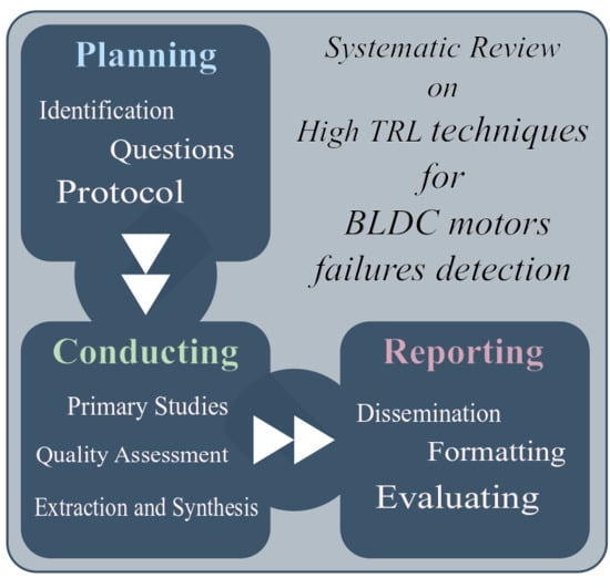
1. Introduction
- Planning the review
- identification of the need
- research questions
- review protocol
- evaluating protocol
- Conducting the review
- selection of primary studies
- study quality assessment
- extraction and synthesis of data
- Reporting the review
- specifying dissemination mechanisms
- formatting the main report
- evaluating the report
2. Planning
2.1. Research Questions
- RQ.1:
- Which are the most common faults of BLDC motors?
- RQ.2:
- Which parameters are used for fault detection in BLDC motors?
- RQ.3:
- Which type of failure can be detected by each technique?
- RQ.4:
- Which technique requires less computational power?
- RQ.5:
- Which technique requires less sensors?
- RQ.6:
- Which technique gives the best results for each type of failure?
2.2. Review Protocol
- IEEE Xplore Digital Library
- Scopus
- ACM Digital Library
- Science Direct
- Web of Science
- Data of the article (e.g., author, year of publication, etc.)
- The type of failure
- The type of technique used
- The type of sensors used
- If it presents experiments or simulations
- If the algorithm has been tested at different speeds or loads
- If the algorithm has been tested in dynamic or stationary conditions
3. Conducting
- to significantly reduce the large number of studies that have been obtained, by using the inclusion and exclusion criteria,
- to extract a features table in which the main characteristics of each article are highlighted.
3.1. Selection of Primary Studies
3.2. Study Quality Assessment
3.3. Extraction and Synthesis Of Data
- Year of publication;
- The category of the detected fault. This field can be one or more of the following items: armature faults, mechanical faults or permanent magnet faults;
- The class of the technique used for the detection. The main categories have been selected to be:
- -
- Radio-frequency emissions monitoring,
- -
- Electromagnetic field monitoring,
- -
- Infrared recognition,
- -
- Noise and vibration monitoring,
- -
- Model, AI, and neural-network-based techniques,
- -
- Temperature measurements,
- -
- Chemical analysis,
- -
- Acoustic noise measurements,
- -
- Parameters estimation,
- -
- MCSA,
- -
- Other (specify).
The last item has been left if some technique cannot be classified into the previously listed categories; - The sensor(s) needed for the failure detection technique implementation;
- If the demonstration of the effectiveness of the proposed detection techniques has been carried out with simulations and/or experiments;
- If the simulations and/or experiments have been carried out under different working conditions, such as different speeds and/or different loads;
- If the proposed technique is capable of working during changes in load and/or speed or the working conditions should be kept stationary;
- Other limitations and/or advantages. This feature is the only one that is subjective, but it contains useful information that cannot be collected in the other features.
4. Reporting
4.1. Discussion
- radio-frequency emissions monitoring,
- temperature measurements,
- infrared recognition,
- chemical analysis.
4.1.1. Rq.1: Most Common Failures of Bldc Motors
4.1.2. Rq.2: Parameters Used for Failure Detection in Bldc Motors
- Output torque
- Torque-meters shall be used to measure this variable and it can provide very useful information. The problem resides in the fact that this type of sensors are often big and expensive.
- Current
- The current is always already measured by the motor controller and there are an immense quantity of failure detection algorithms based on this variable.
- Voltage
- The voltage is also commonly measured by the motor controller.
- Vibrations
- By placing accelerometers on the motor, it is possible to measure its vibration level. The algorithms based on vibration analysis could present problems when used in moving systems, like aircraft, due to the coupling of external and unpredictable vibrations.
- Magnetic flux
- The magnetic flux gives a deep insight on how the motor is working. In order to measure it, it is usually necessary to include in the motor winding so called search coils, i.e., some additional windings not connected to the phases. The inclusion of these additional coils is not common and, although being a simple procedure, it need to unmount the motor, rewound it and to extract from the interior as many pairs of wires as many search coils as are inserted. An alternative to this procedure is to place external magnetic sensors on the stator to sense the stray magnetic fields.
- Back-EMF,
- Magnetic flux,
- Winding resistance,
- Winding inductance.
4.1.3. Rq.3: Type of Failures Detectable by Each Technique
4.1.4. Rq.4: Computational Power Needed for Each Technique
4.1.5. Rq.5: Sensors Needed for Each Technique
4.1.6. Rq.6: Best Detection Results
4.2. General Considerations About The Techniques
5. Conclusions
Author Contributions
Funding
Conflicts of Interest
Abbreviations
| AI | Artificial Intelligence |
| BLDC | Brushless Direct Current |
| FEM | Finite Element Method |
| HF | High Frequency |
| MCSA | Motor Current Signature Analysis |
| NN | Neural Network |
| SR | Systematic Review |
| SVM | Support Vector Machine |
| TRL | Technology Readiness Level |
Appendix A. Nomenclature
- Fault :
- Unpermitted deviation of at least one feature (characteristic property) of the system out of the acceptable standard condition threshold. The fault is a state of the system and can be of various types (manufacturing, assembly, maintenance, software, operators, wrong operation). It may not affect the correct functioning of the overall system
- Failure :
- Permanent interruption of a system’s ability to perform a required function under determined operating conditions.
- Malfunction :
- Intermittent irregularity in the fulfilment of a system’s function. It can arise from one or more faults.

References
- Fico, V.M.; Vázquez, A.L.R.; Prats, M.Á.M.; Bernelli-Zazzera, F. Failure detection by signal similarity measurement of brushless DC motors. Energies 2019, 12. [Google Scholar] [CrossRef]
- Basak, D.; Tiwari, A.; Das, S.P. Fault diagnosis and condition monitoring of electrical machines-A review. In Proceedings of the IEEE International Conference on Industrial Technology, Mumbai, India, 15–17 December 2006; pp. 3061–3066. [Google Scholar] [CrossRef]
- Buchwald, H.; Avidor, Y.; Braunwald, E.; Jensen, M.D.; Pories, W.; Fahrbach, K.; Schoelles, K. Bariatric surgery: A systematic review and meta-analysis. JAMA 2004, 292, 1724–1737. [Google Scholar] [CrossRef] [PubMed]
- Renehan, A.G.; Tyson, M.; Egger, M.; Heller, R.F.; Zwahlen, M. Body-mass index and incidence of cancer: A systematic review and meta-analysis of prospective observational studies. Lancet 2008, 371, 569–578. [Google Scholar] [CrossRef]
- Kitchenham, B.; Charters, S. Guidelines for performing systematic literature reviews in software engineering. In EBSE Technical Report; Elsevier: Amsterdam, The Netherlands, 2007; pp. 1–65. [Google Scholar]
- Hall, T.; Beecham, S.; Bowes, D.; Gray, D.; Counsell, S. A systematic literature review on fault prediction performance in software engineering. IEEE Trans. Softw. Eng. 2011, 38, 1276–1304. [Google Scholar] [CrossRef]
- Kitchenham, B.; Brereton, O.P.; Budgen, D.; Turner, M.; Bailey, J.; Linkman, S. Systematic literature reviews in software engineering—A systematic literature review. Inf. Softw. Technol. 2009, 51, 7–15. [Google Scholar] [CrossRef]
- Ierardi, C.; Orihuela, L.; Jurado, I. Distributed Estimation Techniques for Cyber-Physical Systems: A Systematic Review. Sensors 2019, 19, 4720. [Google Scholar] [CrossRef]
- Ge, Y.; Song, B.; Pei, Y.; Mollet, Y.A.; Gyselinck, J.J. Analytical Expressions of Isolation Indicators for Permanent-Magnet Synchronous Machines Under Stator Short-Circuit Faults. IEEE Trans. Energy Convers. 2019, 34, 984–992. [Google Scholar] [CrossRef]
- Kao, I.H.; Wang, W.J.; Lai, Y.H.; Perng, J.W. Analysis of Permanent Magnet Synchronous Motor Fault Diagnosis Based on Learning. IEEE Trans. Instrum. Meas. 2019, 68, 310–324. [Google Scholar] [CrossRef]
- Heydarzadeh, M.; Zafarani, M.; Nourani, M.; Akin, B. A Wavelet-Based Fault Diagnosis Approach for Permanent Magnet Synchronous Motors. IEEE Trans. Energy Convers. 2019, 34, 761–772. [Google Scholar] [CrossRef]
- Zandi, O.; Poshtan, J. Fault Diagnosis of Brushless DC Motors Using Built-In Hall Sensors. IEEE Sensors J. 2019, 19, 8183–8190. [Google Scholar] [CrossRef]
- Liu, X.; Miao, W.; Xu, Q.; Cao, L.; Liu, C.; Pong, P.W.T. Inter-Turn Short-Circuit Fault Detection Approach for Permanent Magnet Synchronous Machines Through Stray Magnetic Field Sensing. IEEE Sens. J. 2019, 1. [Google Scholar] [CrossRef]
- Ye, M.; Huang, J. Bearing Fault Diagnosis under Time-Varying Speed and Load Conditions via Speed Sensorless Algorithm and Angular Resample. In Proceedings of the 2018 23rd International Conference on Electrical Machines (ICEM 2018), Alexandroupoli, Greece, 3–6 September 2018; pp. 1775–1781. [Google Scholar] [CrossRef]
- Ullah, Z.; Lee, S.; Hur, J. A Novel Fault Diagnosis Technique for IPMSM Using Voltage Angle. In Proceedings of the 2018 IEEE Energy Conversion Congress and Exposition (ECCE), Portland, OR, USA, 23–27 September 2018; pp. 3236–3243. [Google Scholar] [CrossRef]
- Moon, S.; Jeong, H.; Lee, H.; Kim, S.W. Interturn Short Fault Diagnosis in a PMSM by Voltage and Current Residual Analysis With the Faulty Winding Model. IEEE Trans. Energy Convers. 2018, 33, 190–198. [Google Scholar] [CrossRef]
- Ahsanullah, K.; Jeyasankar, E.; Vignesh, A.; Panda, S.; Shanmukha, R.; Nadarajan, S. Eccentricity fault analysis in PMSM based marine propulsion motors. In Proceedings of the 20th International Conference on Electrical Machines and Systems, Sydney, NSW, Australia, 11–14 August 2017; pp. 1–6. [Google Scholar]
- Breuneval, R.; Clerc, G.; Nahid-Mobarakeh, B.; Mansouri, B. Hybrid diagnosis of intern-turn short-circuit for aircraft applications using SVM-MBF. In Proceedings of the 2017 IEEE International Conference on Fuzzy Systems (FUZZ-IEEE), Cincinnati, OH, USA, 1–5 October 2017; pp. 1–6. [Google Scholar]
- Heydarzadeh, M.; Zafarani, M.; Ugur, E.; Akin, B.; Nourani, M. A model-based signal processing method for fault diagnosis in PMSM machine. In Proceedings of the Energy Conversion Congress and Exposition (ECCE), Naples, Italy, 9–12 July 2017; pp. 3160–3164. [Google Scholar]
- Mazzoletti, M.A.; Bossio, G.R.; De Angelo, C.H.; Espinoza-Trejo, D.R. A model-based strategy for interturn short-circuit fault diagnosis in PMSM. IEEE Trans. Ind. Electron. 2017, 64, 7218–7228. [Google Scholar] [CrossRef]
- Obeid, N.H.; Battiston, A.; Boileau, T.; Nahid-Mobarakeh, B. Early Intermittent Interturn Fault Detection and Localization for a Permanent Magnet Synchronous Motor of Electrical Vehicles Using Wavelet Transform. IEEE Trans. Transp. Electrif. 2017, 3, 694–702. [Google Scholar] [CrossRef]
- Park, Y.; Fernandez, D.; Lee, S.B.; Hyun, D.; Jeong, M.; Kommuri, S.K.; Cho, C.; Reigosa, D.; Briz, F. On-line detection of rotor eccentricity for PMSMs based on hall-effect field sensor measurements. In Proceedings of the Energy Conversion Congress and Exposition (ECCE), Cincinnati, OH, USA, 1–5 October 2017; pp. 4678–4685. [Google Scholar]
- Zhu, M.; Hu, W.; Kar, N.C. Torque-ripple-based interior permanent-magnet synchronous machine rotor demagnetization fault detection and current regulation. IEEE Trans. Ind. Appl. 2017, 53, 2795–2804. [Google Scholar] [CrossRef]
- Gu, B.G. Study of IPMSM interturn faults part II: Online fault parameter estimation. IEEE Trans. Power Electron. 2016, 31, 7214–7223. [Google Scholar] [CrossRef]
- Jeong, H.; Moon, S.; Lee, J.; Kim, S.W. Inter-turn short fault diagnosis of permanent magnet synchronous machines using negative sequence components. In Proceedings of the 2016 IEEE International Conference on Industrial Technology (ICIT), Taipei, Taiwan, 14–17 March 2016; pp. 170–174. [Google Scholar]
- Mbo’o, C.P.; Hameyer, K. Fault diagnosis of bearing damage by means of the linear discriminant analysis of stator current features from the frequency selection. IEEE Trans. Ind. Appl. 2016, 52, 3861–3868. [Google Scholar] [CrossRef]
- Moon, S.; Lee, J.; Jeong, H.; Kim, S.W. Demagnetization fault diagnosis of a PMSM based on structure analysis of motor inductance. IEEE Trans. Ind. Electron. 2016, 63, 3795–3803. [Google Scholar] [CrossRef]
- Sen, B.; Wang, J. Stator interturn fault detection in permanent-magnet machines using PWM ripple current measurement. IEEE Trans. Ind. Electron. 2016, 63, 3148–3157. [Google Scholar] [CrossRef]
- Abed, W.; Sharma, S.; Sutton, R.; Motwani, A. A robust bearing fault detection and diagnosis technique for brushless DC motors under non-stationary operating conditions. Control. Autom. Electr. Syst. 2015, 26, 241–254. [Google Scholar] [CrossRef]
- Akar, M.; Hekim, M.; Orhan, U. Mechanical fault detection in permanent magnet synchronous motors using equal width discretization-based probability distribution and a neural network model. Electr. Eng. Comput. Sci. 2015, 23, 813–823. [Google Scholar] [CrossRef]
- Çira, F.; Arkan, M.; Gümüş, B. A new approach to detect stator fault in permanent magnet synchronous motors. In Proceedings of the 2015 IEEE 10th International Symposium on Diagnostics for Electrical Machines, Power Electronics and Drives (SDEMPED), Guarda, Portugal, 1–4 September 2015; pp. 316–321. [Google Scholar]
- Lee, S.T.; Kim, K.T.; Hur, J. Diagnosis technique for stator winding inter-turn fault in BLDC motor using detection coil. In Proceedings of the 2015 9th International Conference on Power Electronics and ECCE Asia (ICPE-ECCE Asia), Seoul, Korea, 1–5 June 2015; pp. 2925–2931. [Google Scholar]
- Moosavi, S.; Djerdir, A.; Ait-Amirat, Y.; Khaburi, D. ANN based fault diagnosis of permanent magnet synchronous motor under stator winding shorted turn. Electr. Power Syst. Res. 2015, 125, 67–82. [Google Scholar] [CrossRef]
- Chakraborty, S.; Keller, E.; Ray, A.; Mayer, J. Detection and estimation of demagnetization faults in permanent magnet synchronous motors. Electr. Power Syst. Res. 2013, 96, 225–236. [Google Scholar] [CrossRef]
- Haddad, R.Z.; Strangas, E.G. Fault detection and classification in permanent magnet synchronous machines using Fast Fourier Transform and Linear Discriminant Analysis. In Proceedings of the 2013 9th IEEE International Symposium on Diagnostics for Electric Machines, Power Electronics and Drives (SDEMPED), Valencia, Spain, 27–30 August 2013; pp. 99–104. [Google Scholar]
- Nyanteh, Y.D.; Srivastava, S.K.; Edrington, C.S.; Cartes, D.A. Application of artificial intelligence to stator winding fault diagnosis in Permanent Magnet Synchronous Machines. Electr. Power Syst. Res. 2013, 103, 201–213. [Google Scholar] [CrossRef]
- Sarikhani, A.; Mohammed, O.A. Inter-turn fault detection in PM synchronous machines by physics-based back electromotive force estimation. IEEE Trans. Ind. Electron. 2013, 60, 3472–3484. [Google Scholar] [CrossRef]
- Urresty, J.C.; Riba, J.R.; Romeral, L. Diagnosis of interturn faults in PMSMs operating under nonstationary conditions by applying order tracking filtering. IEEE Trans. Power Electron. 2013, 28, 507–515. [Google Scholar] [CrossRef]
- Abu-Rub, H.; Ahmed, S.M.; Iqbal, A.; Toliyat, H.A.; Rahimian, M.M. Incipient bearing fault detection for three-phase Brushless DC motor drive using ANFIS. In Proceedings of the IEEE International Symposium on Diagnostics for Electric Machines, Power Electronics & Drives, Bologna, Italy, 5–8 September 2011; pp. 620–625. [Google Scholar]
- Leboeuf, N.; Boileau, T.; Nahid-Mobarakeh, B.; Clerc, G.; Meibody-Tabar, F. Real-time detection of interturn faults in PM drives using back-EMF estimation and residual analysis. IEEE Trans. Ind. Appl. 2011, 47, 2402–2412. [Google Scholar] [CrossRef]
- Arellano-Padilla, J.; Sumner, M.; Gerada, C. Winding condition monitoring scheme for a permanent magnet machine using high-frequency injection. IET Electr. Power Appl. 2011, 5, 89–99. [Google Scholar] [CrossRef]
- Kim, K.H.; Gu, B.G.; Jung, I.S. Online fault-detecting scheme of an inverter-fed permanent magnet synchronous motor under stator winding shorted turn and inverter switch open. IET Electr. Power Appl. 2011, 5, 529–539. [Google Scholar] [CrossRef]
- Ondel, O.; Boutleux, E.; Clerc, G. Diagnosis by pattern recognition for PMSM used in more electric aircraft. In Proceedings of the IECON 2011-37th Annual Conference on IEEE Industrial Electronics Society, Melbourne, VIC, Australia, 7–10 November 2011; pp. 3452–3458. [Google Scholar]
- Ebrahimi, B.; Faiz, J.; Araabi, B. Pattern identification for eccentricity fault diagnosis in permanent magnet synchronous motors using stator current monitoring. IET Electr. Power Appl. 2010, 4, 418–430. [Google Scholar] [CrossRef]
- Ebrahimi, B.M.; Faiz, J. Feature extraction for short-circuit fault detection in permanent-magnet synchronous motors using stator-current monitoring. IEEE Trans. Power Electron. 2010, 25, 2673–2682. [Google Scholar] [CrossRef]
- Quiroga, J.; Cartes, D.; Edrington, C.; Liu, L. Neural network based fault detection of PMSM stator winding short under load fluctuation. In Proceedings of the 13th Power Electronics and Motion Control Conference, Poznan, Poland, 1–3 September 2008; pp. 793–798. [Google Scholar]
- Rosero, J.; Cusido, J.; Garcia, A.; Romeral, L.; Ortega, J. Fault detection of eccentricity by means of joint time-frequency analysis in PMSM under dynamic conditions. In Proceedings of the International Symposium on Intelligent Signal Processing, Alcala de Henares, Spain, 3–5 October 2007; pp. 1–6. [Google Scholar]
- Rosero, J.; Cusido, J.; Ortega, J.; Romeral, L.; Garcia, A. PMSM Bearing Fault Detection by means of Fourier and Wavelet transform. In Proceedings of the IECON 2007—33rd Annual Conference of the IEEE Industrial Electronics Society, Taipei, Taiwan, 5–8 November 2007; pp. 1163–1168. [Google Scholar]
- Rosero, J.; Cusido, J.; Garcia, A.; Romeral, L.; Ortega, J. Detection of stator short circuits in PMSM by mean of joint time-frequency analysis. In Proceedings of the IEEE International Symposium on Diagnostics for Electric Machines, Power Electronics and Drives (SDEMPED 2007), Cracow, Poland, 6–8 September 2007; pp. 420–425. [Google Scholar]
- Barendse, P.; Pillay, P. A new algorithm for the detection of faults in permanent magnet machines. In Proceedings of the IECON 2006 - 32nd Annual Conference on IEEE Industrial Electronics, Paris, France, 6–10 November 2006; pp. 823–828. [Google Scholar]
- Rajagopalan, S.; Aller, J.M.; Restrepo, J.A.; Habetler, T.G.; Harley, R.G. Detection of rotor faults in brushless DC motors operating under nonstationary conditions. IEEE Trans. Ind. Appl. 2006, 42, 1464–1477. [Google Scholar] [CrossRef]
- Ierardi, C.; Orihuela, L.; Jurado, I. Guidelines for a systematic review in systems and automatic engineering. In Case study: Distributed estimation techniques for cyber-physical systems. In Proceedings of the European Control Conference, Limassol, Cyprus, 12–15 June 2018; pp. 2230–2235. [Google Scholar]
- Moher, D.; Liberati, A.; Tetzlaff, J.; Altman, D. Reprint-preferred reporting items for systematic reviews and meta-analyses: The PRISMA statement. Phys. Ther. 2009, 89, 873–880. [Google Scholar] [CrossRef] [PubMed]
- Nandi, S.; Toliyat, H.A.; Li, X. Condition monitoring and fault diagnosis of electrical motors-A review. IEEE Trans. Energy Convers. 2005, 20, 719–729. [Google Scholar] [CrossRef]
- Heydarzadeh, M.; Zafarani, M.; Akin, B.; Nourani, M. Automatic fault diagnosis in PMSM using adaptive filtering and wavelet transform. In Proceedings of the 2017 IEEE International Electric Machines and Drives Conference (IEMDC), Miami, FL, USA, 21–24 May 2017; pp. 1–7. [Google Scholar]
- Isermann, R. Fault-Diagnosis Systems: An Introduction from Fault Detection to Fault Tolerance; Springer: Berlin, Germany, 2006; pp. 1–475. [Google Scholar] [CrossRef]


| Cite | Year | Fault Type | Technique Used | Sensors Used | Experiments or Simulations | Various Speed/Loads | Working Condition | Limitations/ Advantages |
|---|---|---|---|---|---|---|---|---|
| [9] | 2019 | Armature faults | Parameters Estimation | Voltage, Current and Position sensors | Both | Both | Stationary conditions | It propose indicators deduced from symmetrical component of phase currents in the reference frame. The method has been validate at various speed, loads and short circuit resistance magnitude for ITSC and at constant speed, load, resistance magnitude for PPSC. The algorithm computational load is nos specified. |
| [10] | 2019 | Permanent Magnetic faults | Model, AI and neural-network-based techniques | Voltage and Current sensors | Both | Various Speed | Stationary conditions | Experimentally tested with 5 motor conditions (1 healthy, 4 faulty) with good detection performances. Proposes two failure extraction methods and compares them. Training time and computational load not specified. |
| [11] | 2019 | Mechanical faults | MCSA | Voltage and Current sensors | Both | Both | Stationary conditions | Uses wavelet decomposition of the current signal and an adaptive filter to estimate and remove the fundamental component. Tested using two case studies, i.e., broken magnet and eccentricity fault, automatic fault classification with SVM and average accuracy of 96%. Training time and computational load not specified. |
| [12] | 2019 | Permanent Magnetic faults | Other (Hall Effect Sensors flux analysis) | Hall Effect Sensors | Experiments | Various Speed | Non-Stationary conditions | Method capable of detecting bearing and permanent magnets faults by analysing respectively the cascade DWT-CWT transform of the speed signal and the kurtosis index of the duty cycle signal of the hall sensor output. Electrically independent from the motor. Influence of load not specified. Computational load not specified. |
| [1] | 2019 | Permanent Magnetic faults | Other (Signals Similarity Analysis) | Voltage and Current sensors | Both | Various Speed | Stationary Conditions | The method has been tested with FEM simulations and experimentally with good results. The test effect of torque on the method has not benn evaluated. The method can be used only for multipole motors. |
| [13] | 2019 | Armature faults | Electromagnetic field monitoring | Tunneling Magnetoresistive sensors | Both | Both | Stationary Conditions | The method is capable of detecting both location and severity of inter-turn short-circuit by sensing the stray magnetic field outside the stator yoke. It needs the installation of TM sensors around the motor body. Computational load not specified. |
| [14] | 2018 | Mechanical faults | Other (Angular Resample) | Voltage and Current sensors | Experiments | Both | Non-Stationary conditions | Method based on the angular resample of speed obtained with a sensorless observer. Computational load not specified. Torque variation not specified. |
| [15] | 2018 | Permanent Magnetic faults | Other (Voltage Angle) | Voltage and Current sensors | Both | Various Speed | Stationary Conditions | The method takes advantage from the variations of the voltage angle observed during demagnetisation and inter-turns short faults to identify their presence. The method is temperature-dependant. A clear detection threshold is not defined. Computational load not specified. |
| Cite | Year | Fault Type | Technique Used | Sensors used | Experiments or Simulations | Various Speed/Loads | Working Condition | Limitations/ Advantages |
|---|---|---|---|---|---|---|---|---|
| [16] | 2018 | Armature faults | Parameters Estimation | Current and Voltage sensors | Both | Both | Stationary condition | The method is affected by the magnitude of the stator current, should be used in constant torque conditions. |
| [17] | 2017 | Mechanical faults | Electromagnetic field monitoring, search coils, coils wound around motor shafts | Search coil | Simulations | Various Speeds | Stationary Conditions | The method is independent from motor variables, but needs the search coil to be installed on the stator. |
| [18] | 2017 | Armature faults | Model, AI, and neural-network -based techniques, Parameters Estimation | Current, Voltage and Speed sensors | Experiments | Both | Stationary Conditions | This method has been tested experimentally on an aeronautical motor, but the experiment set-up has not been presented. The algorithm is very fast (≈ 15 msec), but the computation time for the features is not taken into account. Also it needs a large database for training the algorithm. |
| [19] | 2017 | Permanent Magnetic and Mechanical faults | Model, AI, and neural -network-based techniques | Current sensor | Experiments | Various Loads | Stationary Conditions | Two failures introduced on an experimental platform and a 10-fold validation of the algorithm is executed. The algorithm is fast (30 msec), but the training time is not specified. |
| [20] | 2017 | Armature faults | Parameters Estimation | Current and Voltage sensors | Both | Both | Non-Stationary Conditions | The proposed method is just slightly dependent from the load and speed. The authors also demonstrated robustness against parameters variation and inaccuracies by introducing a threshold, but the allowed tolerance is not specified and this quantity can also depend on the motor. |
| [21] | 2017 | Armature faults | MCSA | Current and Voltage sensors | Both | Both | Stationary Conditions | The proposed method is particularised for intermittent faults. The test set-up is not presented. Tests at various loads and speeds have been executed, but their influence on the method is not specified. |
| [22] | 2017 | Mechanical faults | Other (Hall Effect Sensors flux analysis) | Analogue or Digital Hall sensors | Both | Various Loads | Stationary Conditions | The method is independent from speed and demonstrates only a slight dependence from loads. The best accuracy is obtained with analogue Hall effect sensor which are not common, even if the authors provide an alternative based on digital Hall effect sensors. This method can be used only if the Hall sensors are placed in the radial direction. |
| [23] | 2017 | Permanent Magnetic faults | Other (Torque Ripple Analysis) | Torque sensor | Both | Various Loads | Stationary Conditions | No information is given about how the motor speed affects the proposed method. A torque transducer is needed to apply the algorithm. |
| Cite | Year | Fault Type | Technique Used | Sensors Used | Experiment or Simulations | Various Speed/Loads | Working Condition | Limitations/ Advantages |
|---|---|---|---|---|---|---|---|---|
| [24] | 2016 | Armature faults | Parameters estimation | Current, Voltage and Speed sensor | Both | Various Speeds | Non-Stationary Conditions | The method is based on a modified motor model. It is based on computations in the rotating frame (dq). No information about how the load affects the detection method is given. |
| [25] | 2016 | Armature faults | Parameters Estimation | Current and Speed sensors | Experiments | Various speeds | Stationary Conditions | The proposed fault index has a very reduced dependence from motor speed. |
| [26] | 2016 | Mechanical faults | MCSA, Model, AI and NN-based techniques | Current Sensor | Experiments | Various Speeds | Stationary Conditions | The implementation is very close to a real scenario, but in some studied conditions the fail rate of the classifier is relatively high. |
| [27] | 2016 | Permanent Magnetic Faults | Parameters Estimation | Current, Speed and Angle Sensors | Both | Both | Non-Stationary Conditions | The method needs the knowledge of various motor parameters and their variation (or incorrectness) can result in poor diagnosis performances. The authors demonstrated good performances with various demagnetisation levels and working conditions. |
| [28] | 2016 | Armature faults | Other (PWM Ripple Current Measurements) | Current and Voltage sensors | Both | Both | Stationary Conditions | The method needs an electric model of the motor valid for high frequencies. The author demonstrated good sensitivity also at low speed. |
| [29] | 2015 | Mechanical faults | Noise and Vibration Monitoring, Model, AI, NN based techniques, MCSA | Current sensor and Accelerometer | Both | Both | Non-Stationary Conditions | The method is capable to detect and distinguish different bearing failures. Need an accelerometer to be placed close to the bearing. |
| [30] | 2015 | Mechanical faults | Model, AI, NN-based techniques | Current sensor | Experiments | Both | Stationary Conditions | The authors performed an extensive experiment campaign with good results. From the images in the article, the damages reproduced on the bearing appear to be considerable. |
| [31] | 2015 | Armature faults | Model, AI and NN-based techniques, MCSA | Current sensor | Experiments | Both | Stationary Conditions | High detection ratio. The frequency analysis is did with the FFT, this means that during the 12 s of signal acquisition the motor speed and load shall be constant. |
| [32] | 2015 | Armature faults | Electromagnetic field monitoring, Search Coils, Coils wound around motor shaft | Search coil | Both | Various Speeds | Stationary Conditions | The presented method is invasive for an already built motor. The detection time is very short (3–5) ms but it seems be dependent on motor speed; furthermore the hardware used for computations is not presented. |
| [33] | 2015 | Armature faults | Model, AI and NN-based techniques, MCSA | Current sensors | Both | Both | Stationary Conditions | The motor used for experiments has an inherent anomaly, but the algorithm is capable to discern it from the short-circuit. The presented method does not imply any previous knowledge on the motor. They uses FFT, it implies that during the signal acquisition the conditions need to be stationary. |
| Cite | Year | Fault Type | Technique Used | Sensors Used | Experiment or Simulations | Various Speed/Loads | Working Condition | Limitations/ Advantages |
|---|---|---|---|---|---|---|---|---|
| [34] | 2013 | Permanent Magnets faults | Model, AI and NN-based techniques, Parameters Estimation | Current, Voltage and Speed sensors | Experiments | Various loads | Stationary Conditions | Proposes a method for demagnetisation. Comparison of the proposed method with various other established methods. |
| [35] | 2013 | Armature, Permanent Magnets and Mechanical Faults | Model, AI, NN-based techniques, MCSA | Current sensors | Simulations | Both | Stationary Conditions | The paper presents a good variety of motors, faults and working conditions. The detection accuracy obtained is very high, but it can be due to the use of clean signals from simulations. |
| [36] | 2013 | Armature faults | Model, AI and NN-based techniques | Current and Voltage Sensors | Both | Both | Stationary Conditions | The training of the AI has been executed with data from both experiments and simulations. The method uses current measurements in time domain with no need of frequency domain transformation. The method is capable of detecting fault severity and location. |
| [37] | 2013 | Armature faults | Parameters estimation | Current, Voltage and Speed sensors | Both | Various loads | Stationary Conditions | The method compares an estimated back-EMF with a reference one for fault detection. The reference is obtained from a FEM model or from an healthy machine. This method can be very sensible to motor parameters change. The influence of the load is not discussed. |
| [38] | 2013 | Armature faults | MCSA | Current, Voltage and Speed sensors | Both | Both | Non-Stationary Conditions | The proposed method has a low computational burden, but needs access to the motor neutral point to be applied. |
| [39] | 2011 | Mechanical faults | Model, AI and NN-based techniques | Current, Speed and Torque sensors, | Simulations | Both | Non-Stationary Conditions | The method tries to detect mechanical faults by estimating the bearing health status. A torque sensor is used, which is not usually mounted in motors and the validation is carried out by simulation without added noise. |
| [40] | 2011 | Armature faults | Parameters estimation | Current, Voltage and Speed sensors | Both | Both | Non-Stationary Conditions | The back-EMF is estimated when the machine is healthy and then frozen, which causes dependence on motor parameters changes. There is a model for compensate the inverter losses compensation. |
| [41] | 2011 | Armature faults | Other (High Frequency Injection) | Current and Angular Position sensors | Both | Various loads | Stationary Conditions | The method has a very good resolution, but the detection is based on a look-up table. This makes the algorithm ignore all the failures (if any) present before the table creation. |
| [42] | 2011 | Armature faults | MCSA | Current sensors | Experiments | Both | Stationary Conditions | Capable of detecting two failures. Use the FFT for the frequency analysis, but detect periods of stationarity of the motor. Use linear interpolation to define the healthy comparison term. |
| Cite | Year | Fault Type | Technique Used | Sensors Used | Experiment or Simulations | Various Speed/Loads | Working Condition | Limitations/ Advantages |
|---|---|---|---|---|---|---|---|---|
| [43] | 2011 | Armature and Mechanical faults | Model, AI NN-based techniques | Current and Voltage senors | Experiments | Various Loads | Stationary Conditions | Perform an interesting multi-class classification based on seven parameters. The algorithm does not seem capable to classify failures not present the training set. |
| [44] | 2010 | Mechanical faults | Model, AI, NN-based techniques, MCSA | Current sensors | Both | Various loads (Load independence demonstrated analytically) | Stationary Conditions | Study on the impact of SNR. |
| [45] | 2010 | Armature faults | Model, AI, NN-based techniques, MCSA | Current sensors | Both | Various loads (Load independence demonstrated analytically) | Stationary Conditions | Study on the impact of SNR. Two failures studied, with fault severity estimation. |
| [46] | 2008 | Armature faults | Model, AI and NN-based techniques | Current, Voltage and Speed sensors | Experiments | Various Loads | Non-Stationary Conditions | Training of a neural-network to predict current and include initial asymmetries. The predicted value of the current is used as a reference to detect failures under load variations. |
| [47] | 2007 | Mechanical faults | MCSA | Current and Voltage sensors | Both | Both | Non-Stationary Conditions | The experimental set-up is not described. There is a comparison between three technique for time-frequency analysis and relative fault detection. |
| [48] | 2007 | Mechanical faults | MCSA | Current and Voltage sensors | Both | Both | Non-Stationary Conditions | The experimental set-up is not described. |
| [49] | 2007 | Mechanical faults | MCSA | Current and Voltage sensors | Both | Various Speeds | Non-Stationary Conditions | The influence of load is not taken into account. The experimental set-up is not described. |
| [50] | 2006 | Armature, Permanent Magnets and Mechanical faults | MCSA | Current and Speed sensors | Experiments | Both | Non-Stationary Conditions | Method for tracking the fault frequencies during variable speed operations. The test set-up is not described. Various faults have been implemented. |
| [51] | 2006 | Mechanical faults | MCSA | Current and Speed sensors | Both | Both | Non-Stationary Conditions | Two methods presented based on different frequency tracking algorithms. Real-time implementation with processor execution time is also included. |
| IE | IT | PE | ES | WB | TF | SP | SI | OX | KO | SA | AS | MP | |
|---|---|---|---|---|---|---|---|---|---|---|---|---|---|
| IEEEX | |||||||||||||
| ACM | |||||||||||||
| Scopus | |||||||||||||
| WoS | |||||||||||||
| SD |
| Database | Studies |
|---|---|
| IEEE Xplore | 842 |
| Web of Science | 590 |
| Scopus | 697 |
| ScienceDirect | 600 |
| ACM Digital Library | 17 |
| 3167 |
| Num. | Description |
|---|---|
| 1 | The technique should not be restricted to a particular machine (number of phases, etc) |
| 2 | Shall propose at least one detection technique (a parameter or an index that clearly and uniquely identifies the failure or an automatic detection algorithm) |
| 3 | The technique shall have been tested at various operation points (different speed or loads or a combination of both) |
| 4 | The technique shall not need special set-ups, configurations, loads or motor manoeuvres |
| 5 | Characteristics of the detection and diagnosis algorithm:
|
| Num. | Description |
|---|---|
| 1 | Grey literature and secondary studies |
| 2 | Non English written papers |
| 3 | Duplicated studies |
| 4 | Full paper not available |
| 5 | Lack of tests or simulations |
| 6 | Use of big sensors, not embeddable in the motor |
| 7 | Not focused on the selected topic |
| Question | Score | |
|---|---|---|
| Is the problem presented clearly? | Yes/Partly/No | |
| Is the methodology used presented clearly? | Yes/Partly/No | |
| Is there a discussion of the results? | Yes/Partly/No | |
| Does it answer to the presented problem(s)? | Yes/Partly/No | |
| Number of cites | Cites | |
| Where was it published? | Journal / Conference |
| Q1 | Q2 | Q3 | Q4 | Q5 | Q6 | |
|---|---|---|---|---|---|---|
| [9] | Y | Y | P | Y | 3 | Journal |
| [10] | Y | P | Y | Y | 12 | Journal |
| [11] | Y | Y | Y | Y | 5 | Journal |
| [12] | Y | P | Y | P | 1 | Journal |
| [1] | Y | Y | Y | Y | 3 | Journal |
| [13] | Y | Y | P | P | 1 | Journal |
| [14] | Y | Y | Y | Y | 2 | Conference |
| [15] | P | Y | Y | P | 1 | Conference |
| [16] | Y | Y | Y | Y | 1 | Journal |
| [17] | Y | Y | P | P | 0 | Conference |
| [18] | Y | P | P | P | 0 | Conference |
| [19] | Y | P | Y | Y | 1 | Conference |
| [20] | Y | Y | Y | Y | 13 | Journal |
| [21] | Y | N | N | P | 2 | Journal |
| [22] | Y | Y | P | Y | 1 | Conference |
| [23] | Y | P | Y | Y | 7 | Journal |
| [24] | P | Y | P | Y | 7 | Journal |
| [25] | Y | P | P | Y | 5 | Conference |
| [26] | Y | Y | Y | Y | 21 | Journal |
| [27] | Y | P | Y | Y | 18 | Journal |
| [28] | Y | Y | Y | Y | 15 | Journal |
| [29] | Y | Y | Y | Y | 5 | Journal |
| [30] | Y | Y | P | Y | 4 | Journal |
| [31] | Y | Y | P | Y | 5 | Conference |
| [32] | Y | Y | P | P | 3 | Conference |
| [33] | Y | P | Y | P | 30 | Journal |
| [34] | P | N | Y | Y | 20 | Journal |
| [35] | Y | P | N | Y | 19 | Conference |
| [36] | Y | P | Y | Y | 24 | Journal |
| [37] | Y | P | P | P | 70 | Journal |
| [38] | Y | P | Y | Y | 68 | Journal |
| [39] | Y | P | P | Y | 5 | Conference |
| [40] | N | Y | Y | Y | 38 | Journal |
| [41] | Y | Y | Y | Y | 45 | Journal |
| [42] | Y | Y | Y | Y | 35 | Journal |
| [43] | Y | P | P | Y | 6 | Conference |
| [44] | Y | P | Y | Y | 45 | Journal |
| [45] | Y | P | Y | Y | 84 | Journal |
| [46] | Y | P | P | Y | 14 | Conference |
| [47] | P | P | P | P | 3 | Conference |
| [48] | P | P | P | P | 13 | Conference |
| [49] | P | P | P | P | 10 | Conference |
| [50] | P | Y | P | P | 18 | Conference |
| [51] | Y | Y | Y | Y | 108 | Journal |
| Noise and Vibration Monitoring | Electromagnetic Field Monitoring | Motor Current Signature Analysis | Model and AI based techniques | Parameters Estimation | |
|---|---|---|---|---|---|
| Advantages | Most suitable method for detecting mechanical faults, as the accelerometers can be placed close to the vibration source | Can directly measure the electromagnetic field inside the motor, does not need complicated algorithm to detect failures, can virtually detect all the motor failures | Does not need additional sensors, can detect a large variety of failures, is the most used technique | Can be used during non-stationary motor operation, can be used in conjunction with other techniques | Can be used during non-stationary motor operation, can virtually monitor every motor parameter |
| Disadvantages | Need to install accelerometers on the motor, measurements can be corrupted by environmental vibrations, difficult to use in non-stationary motor operation | Need to rewind the stator and to extract as many additional cables as many coils inserted | Need to transform the signal in the frequency domain, the motor current depend on the load, cannot be used during non-stationary motor operation | Need extensive training | The method depends on the knowledge of various motor parameters and on the accuracy of the model, their variation (or incorrectness) can result in poor diagnosis performance |
© 2020 by the authors. Licensee MDPI, Basel, Switzerland. This article is an open access article distributed under the terms and conditions of the Creative Commons Attribution (CC BY) license (http://creativecommons.org/licenses/by/4.0/).
Share and Cite
Fico, V.M.; Martín Prats, M.Á.; Ierardi, C. High Technology Readiness Level Techniques for Brushless Direct Current Motors Failures Detection: A Systematic Review. Energies 2020, 13, 1573. https://doi.org/10.3390/en13071573
Fico VM, Martín Prats MÁ, Ierardi C. High Technology Readiness Level Techniques for Brushless Direct Current Motors Failures Detection: A Systematic Review. Energies. 2020; 13(7):1573. https://doi.org/10.3390/en13071573
Chicago/Turabian StyleFico, Vito Mario, María Ángeles Martín Prats, and Carmelina Ierardi. 2020. "High Technology Readiness Level Techniques for Brushless Direct Current Motors Failures Detection: A Systematic Review" Energies 13, no. 7: 1573. https://doi.org/10.3390/en13071573
APA StyleFico, V. M., Martín Prats, M. Á., & Ierardi, C. (2020). High Technology Readiness Level Techniques for Brushless Direct Current Motors Failures Detection: A Systematic Review. Energies, 13(7), 1573. https://doi.org/10.3390/en13071573