Effect of Vacuum Insulation Panels on Energy Consumption and Thermal Load Transfer between Compartments in a Three-Temperature Frost-Free Refrigerator

Abstract
1. Introduction
2. Experiment Apparatus and Procedures
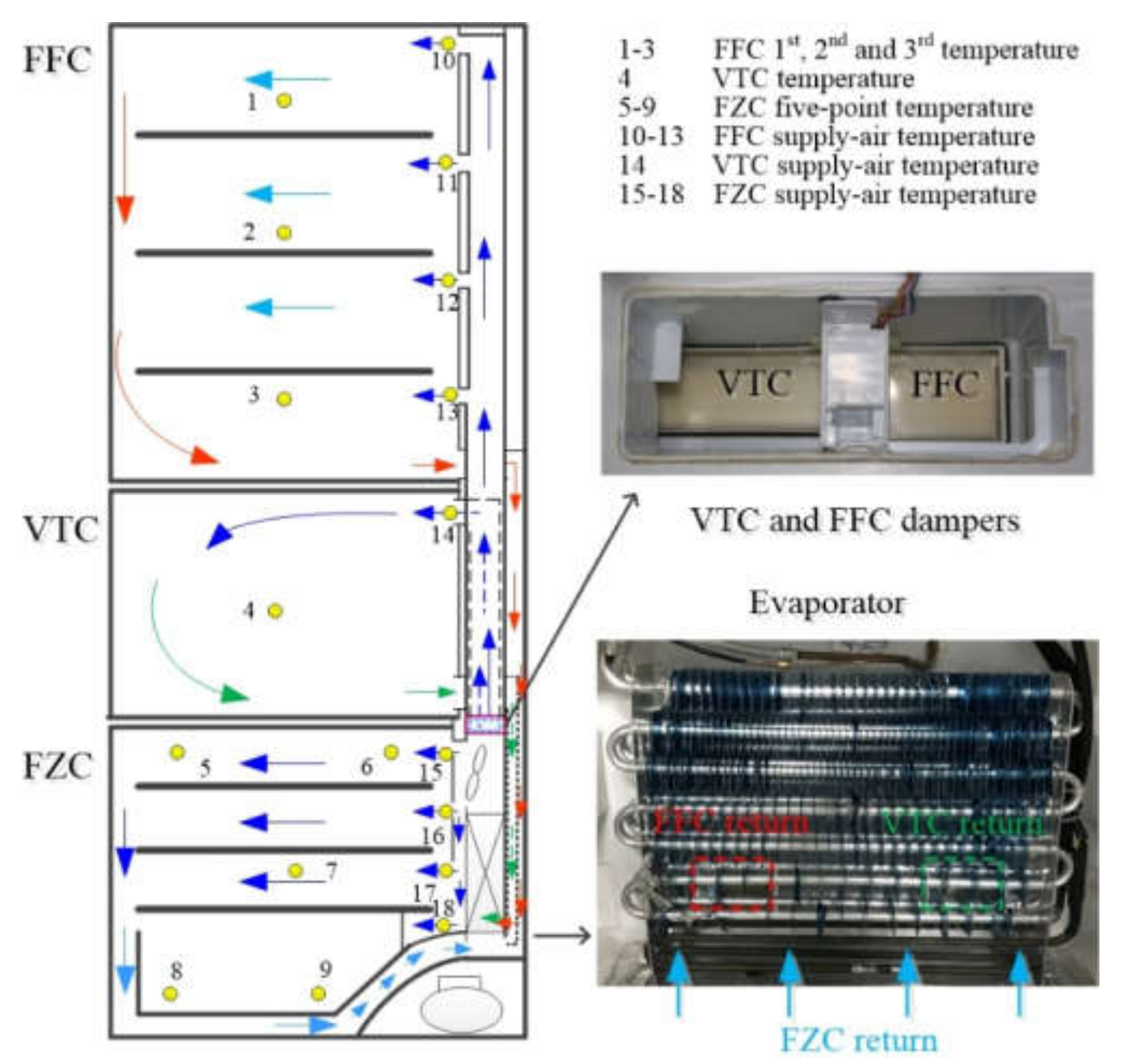
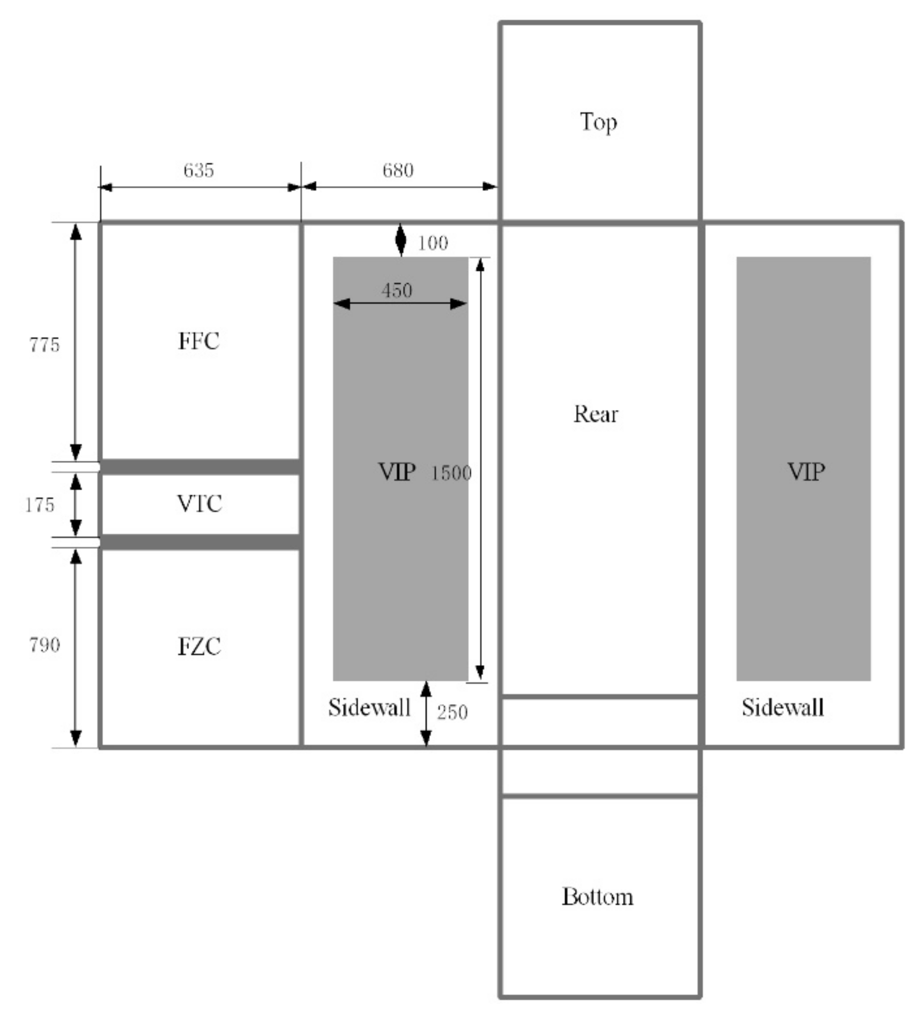
2.1. Experiment Apparatus
2.2. Test Procedures
3. Results and Discussion
3.1. Overall Energy Performance
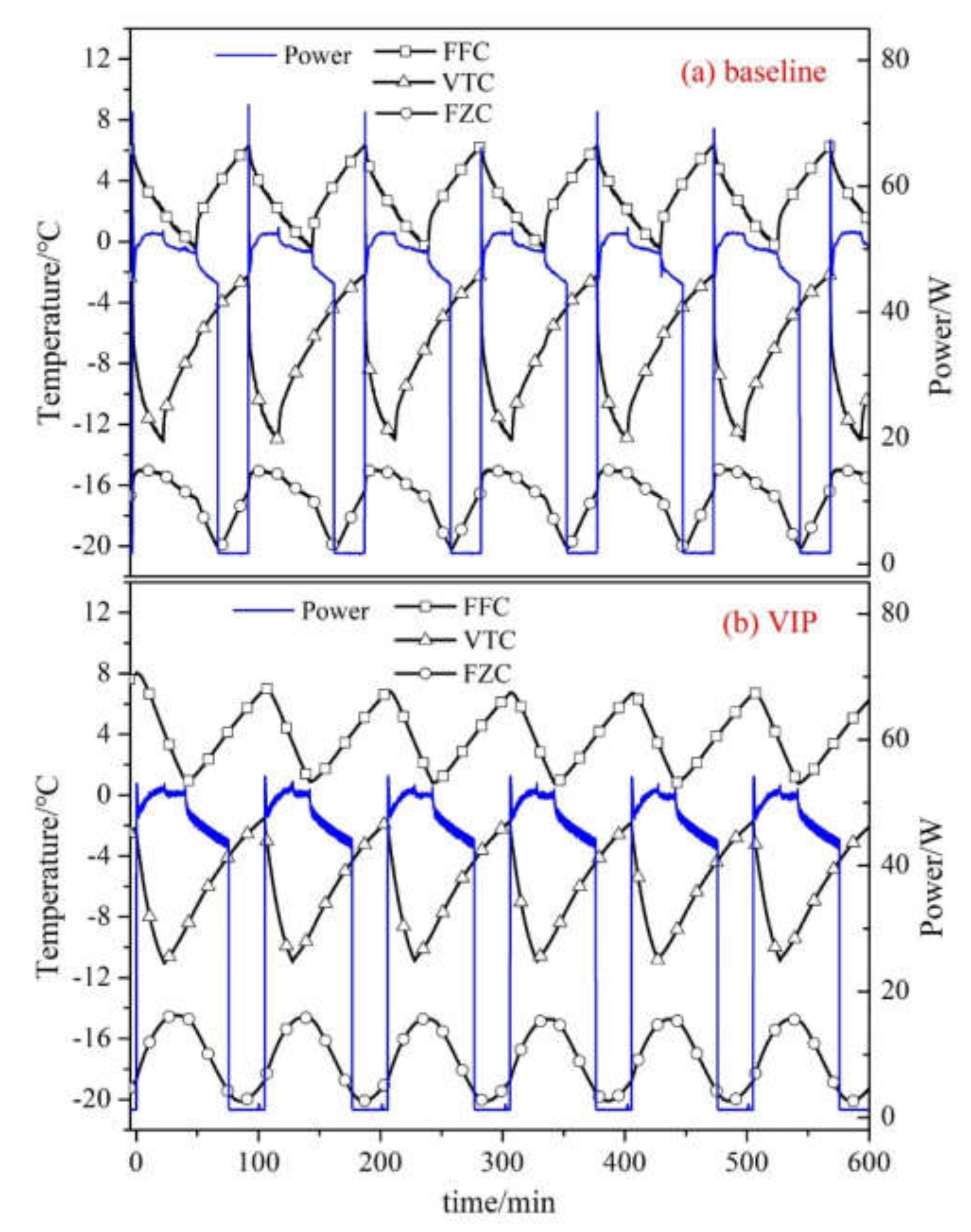
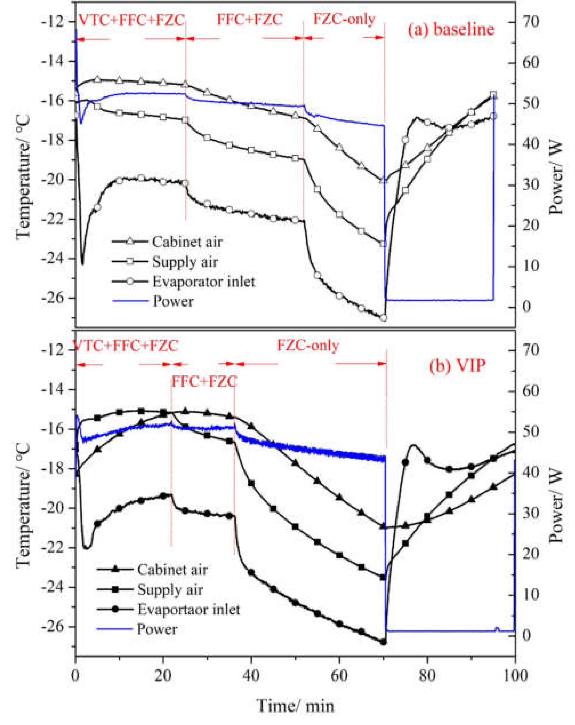
3.2. Dynamic Characteristics
3.3. Thermal Load Transfer
4. Conclusions
- (1)
- VIPs reduce the steady-state energy consumption of the refrigerator by 12.4%, ascribed to the 8.0% lower average power input and 2.9% smaller compressor-off duration.
- (2)
- VIPs accelerate FFC cooling by 27.8% due to better thermal insulation, and therefore shorten the FFC-damper-on duration by 15.5 min. However, the shorter damper-on and longer damper-off durations raise the FFC average temperature by 1.2°C.
- (3)
- The higher FFC cabinet temperature in the VIP case induces thermal load transfer from FFC to FZC through the mixing of return air in the evaporator chamber, thus increasing the FZC-only duration by 15.8 min. Consequently, the compressor-on duration is hardly reduced.
- (4)
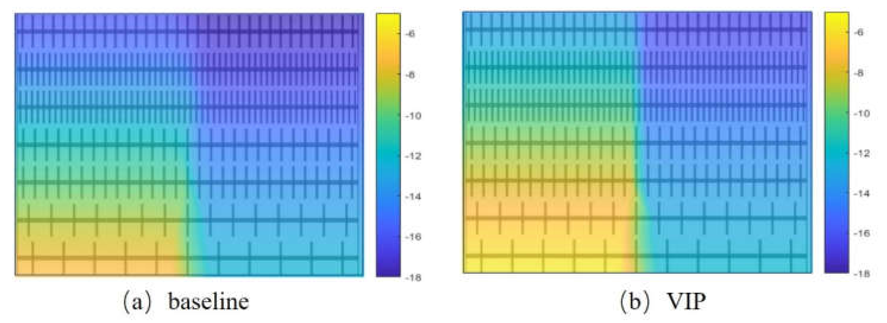
- The simulation results of the heat transfer process through the evaporator in both the baseline and VIP cases were provided to obtain a full view of the thermal load transfer process.
Author Contributions
Funding
Conflicts of Interest
Abbreviations
| FFC | Fresh food compartment |
| VTC | Variable temperature compartment |
| FZC | Freezer compartment |
| VIP | Vacuum insulation panel |
References
- Yoon, W.J.; Jung, H.W.; Chung, H.J.; Kim, Y. Performance optimization of a two-circuit cycle with parallel evaporators for a domestic refrigerator-freezer. Int. J. Refrig. 2011, 34, 216–224. [Google Scholar] [CrossRef]
- Björk, E.; Palm, B. Refrigerant mass charge distribution in a domestic refrigerator. Part I: Transient conditions. Appl. Therm. Eng. 2006, 26, 829–837. [Google Scholar] [CrossRef]
- Björk, E.; Palm, B. Refrigerant mass charge distribution in a domestic refrigerator. Part II: Steady state condition. Appl. Therm. Eng. 2006, 26, 866–871. [Google Scholar] [CrossRef]
- Visek, M.; Jappolo, C.M.; Molinaroli, L.; Olivani, A. Advanced sequential dual-evaporator domestic refrigerator/freezer: System energy optimization. Int. J. Refrig. 2014, 43, 71–79. [Google Scholar] [CrossRef]
- Lu, Z.; Ding, G. Temperature and time-sharing running combination control strategy of two-circuit cycle refrigerator-freezer with parallel evaporators. Appl. Therm. Eng. 2006, 26, 1208–1217. [Google Scholar] [CrossRef]
- Zhang, Z.; Huang, D.; Zhao, R.; Leng, Y. Effect of airflow field optimization around spiral wire-on-tube condenser on a frost-free refrigerator performance. Appl. Therm. Eng. 2017, 114, 785–792. [Google Scholar] [CrossRef]
- Zhao, R.; Huang, D.; Peng, X.; Zhang, Y. Switch loss of a frost-free refrigerator-freezer with parallel dual-evaporator refrigeration system and its mitigation. Sci. Tech. Built Env. 2019, 25, 387–395. [Google Scholar] [CrossRef]
- Cofré-Toledo, J.; Vasco, D.A.; Isaza-Roldán, C.A.; Tangarife, J.A. Evaluation of an integrated household refrigerator evaporator with two eutectic phase-change materials. Int. J. Refrig. 2018, 93, 29–37. [Google Scholar] [CrossRef]
- Xu, J.; Hrnjak, P. Formation, distribution, and movement of oil droplets in the compressor plenum. Int. J. Refrig. 2018, 93, 184–194. [Google Scholar] [CrossRef]
- Xu, J.; Hrnjak, P. Coalescing oil separator for compressors. Int. J. Refrig. 2019, 106, 41–53. [Google Scholar] [CrossRef]
- Xu, J.; Hrnjak, P. Characteristics of oil annular-mist flow in the compressor discharge pipe. Int. J. Refrig. 2019, 107, 145–154. [Google Scholar] [CrossRef]
- Bansal, P.K.; Wich, T.; Browne, M.W. Optimisation of egg-crate type evaporators in domestic refrigerators. Appl. Therm. Eng. 2001, 21, 751–770. [Google Scholar] [CrossRef]
- Boughton, B.E.; Clausing, A.M.; Newell, T.A. An investigation of household refrigerator cabinet thermal loads. HVAC&R Research 1996, 2, 135–147. [Google Scholar]
- Thiessen, S.; Knabben, F.T.; Melo, C.; Gonçalves, J.M. A study on the effectiveness of applying vacuum insulation panelss in domestic refrigerators. Int. J. Refrig. 2018, 96, 10–16. [Google Scholar] [CrossRef]
- Hammond, E.C.; Evans, J.A. Application of vacuum insulation panelss in cold chain-analysis of viability. Int. J. Refrig. 2014, 47, 58–65. [Google Scholar] [CrossRef]
- Trias, F.X.; Oliet, C.; Rigola, J.; Pérez-Segarra, C.D. A simple optimization approach for the insulation thickness distribution in household refrigerators. Int. J. Refrig. 2018, 93, 169–175. [Google Scholar] [CrossRef]
- Sevindir, M.K.; Demir, H.; Ağra Atayılmaz, S.Ö.; Teke, İ. Modelling the optimum distribution of insulation material. Renew. Energy 2017, 113, 74–84. [Google Scholar] [CrossRef]
- Sim, J.S.; Ha, J.S. Experimental study of heat transfer characteristics for a refrigerator by using reverse heat loss method. Int. Commun. Heat Mass Transf. 2011, 38, 572–576. [Google Scholar] [CrossRef]
- Afonso, C.; Castro, M. Air infiltration in domestic refrigerators: The influence of the magnetic seals conservation. Int. J. Refrig. 2010, 33, 856–867. [Google Scholar] [CrossRef]
- Huelsz, G.; Gómez, F.; Piñeirua, M.; Rojas, J.; Alba, M.; Guerra, V. Evaluation of refrigerator/freezer gasket thermal loads. HVAC R Res. 2011, 17, 133–143. [Google Scholar] [CrossRef]
- Kim, H.S.; Sim, J.S.; Ha, J.S. A study on the heat transfer characteristics near the magnetic door gasket of a refrigerator. Heat Mass Transf. 2011, 38, 1226–1231. [Google Scholar] [CrossRef]
- Li, Z.Q.; Zhao, D.; Ding, G.L.; Ren, T.; Miao, S.; Han, X. Effect of enthalpy exchanger on reducing frost accumulation on evaporator in frost-free refrigerator. Int. J. Refrig. 2018, 89, 51–60. [Google Scholar] [CrossRef]
- Zhang, L.; Fujinawa, T.; Saikawa, M. Theoretical study of a frost-free household refrigerator-freezer. Int. J. Refrig. 2016, 62, 60–71. [Google Scholar] [CrossRef]
- Li, Z.Q.; Zhao, D.; Ding, G.L.; Ren, T.; Miao, S.; Han, X.; Noda, T. Improving defrosting performance by controlling frost distribution to match defrosting heat distribution in frost-free household refrigerators. Int. J. Refrig. 2017, 77, 136–148. [Google Scholar] [CrossRef]
- Maldonado, J.M.; Zsembinszki, G.; Gracia, A.D.; Moreno, P.; Albets, X.; González, M.A.; Gabeze, L.F. Control strategies for defrost and evaporator fans operation in walk-in freezers. Int. J. Refrig. 2018, 91, 101–110. [Google Scholar] [CrossRef]
- Liu, Z.B.; Gao, W.Q.; Lang, H.W.; Chi, Y.Y. Experimental study on new type of defrosting system using outdoor air for frost-free household refrigerators. Appl. Therm. Eng. 2018, 134, 256–265. [Google Scholar] [CrossRef]
- Liu, Z.B.; Li, A.; Wang, Q.H.; Chi, Y.Y.; Zhang, L.F. Experimetal study on a new type of thermal storage defrostig system for frost-free household refrigerators. Appl. Therm. Eng. 2017, 118, 256–265. [Google Scholar] [CrossRef]
- Melo, C.; Knabben, F.T.; Pereira, P.V. A experiment study on defrost heaters applied to frost-free household refrigerators. Appl. Therm. Eng. 2013, 51, 239–245. [Google Scholar] [CrossRef]
- Zhao, R.; Huang, D.; Zhang, Z.; Leng, Y. Effect of defrost heat leakage on freezer temperature rise during periodical defrost cycles in a frost-free refrigerator-freezer with an electric heater. Sci. Tech. Built Environ. 2017, 23, 211–217. [Google Scholar] [CrossRef]
- Zhao, R.; Huang, D.; Peng, X.; Yang, H. Reducing cabinet temperature rise during electric heater defrosting of frost-free refrigerators by using a special fan cover to block heat infiltration. Sci. Tech. Built Environ. 2019, 25, 1505–1513. [Google Scholar] [CrossRef]
- Zhao, R.; Huang, D.; Peng, X.; Yang, H. Distributed heaters to reduce temperature rise in freezing cabinet during defrost process and its overall energy effect for a frost-free refrigerator. Int. J. Refrig. 2019, 99, 186–193. [Google Scholar] [CrossRef]
- Zhang, Z.; Huang, D.; Shi, L.; Chi, L. Comparison of independent and synchronous opening control strategies of two air-dampers in three-temperature frost-free refrigerator. Appl. Therm. Eng. 2018, 128, 127–133. [Google Scholar] [CrossRef]
- Knabben, F.T.; Helmes, C.J.L.; Melo, C. In-situ study of frosting and defrosting processes in tube-fin evaporators of household refrigerating appliances. Int. J. Refrig. 2011, 34, 2031–2041. [Google Scholar] [CrossRef]
- Moffat, R.J. Describing the uncertainties in experimental results. Exp. Therm. Fluid Sci. 1998, 1, 3–17. [Google Scholar] [CrossRef]
- Seker, D.; Karatas, H.; Egrican, N. Frost formation on fin-and-tube heat exchangers. Part Ⅰ—Modeling of frost formation on fin-and-tube heat exchangers. Int. J. Refrig. 2004, 27, 367–374. [Google Scholar] [CrossRef]
- Barbosa, J.R.; Melo, C.; Hermes, C.J.L.; Waltrich, P.J. A study of the air-side heat transfer and pressure drop characteristics of tube-fin ‘no-frost’ evaporators. Appl. Energy 2009, 86, 1484–1491. [Google Scholar] [CrossRef]


| Items | Parameters | Items | Parameters |
|---|---|---|---|
| Refrigerator model | BCD-345W | Compressor | Jiaxipera VTH1113Y |
| FZC volume/L | 117 | FFC volume/L | 193 |
| VTC volume/L | 35 | Weight/kg | 95 |
| Throttle device | Capillary tube | Blowing agent | Cyclopentane/VIP |
| Climate class | ST | Refrigerant | R600a |
| Defrost system | Auto electric defrost | Refrigerant charge/g | 52 |
| Cases | Baseline | VIP |
|---|---|---|
| Prototype | three-temperature, single evaporator, capacity supplied by axial fan and air ducts | |
| Insulation | Only cyclopentane | VIPs embedded in cyclopentane |
| Instruments | Thermocouples in cabinets, on evaporator surface and in air ducts; Humidity sensors in return air inlets in all cabinets; Power meter before the plug of the refrigerator. | |
| Test cycles | Four cooling/defrosting cycles with 1st pulling-downing and 2nd~4th normal cooling; | |
| Simulation | Heat transfer on evaporator surface based on temperature/humidity of return air detected by thermocouples and humidity sensors. | |
| Item | Baseline | VIP | Deviation |
|---|---|---|---|
| VTC+FFC+FZC duration/min | 24.67 | 22.07 | −2.6 |
| FF+FZC duration/min | 27.5 | 14.6 | −12.9 |
| FZC-only duration/min | 17.83 | 34.13 | +16.3 |
| Compressor-on duration/min | 70.0 | 70.8 | +0.8 |
| Compressor-off duration/min | 25.0 | 29.27 | +4.27 |
| Compressor-on ratio/% | 73.68 | 70.75 | −2.93 |
| Average power/W | 37.29 | 34.30 | −8.0% |
| Steady-state energy consumption/kW•24 h | 0.659 | 0.577 | −12.4% |
| Cabinet | Baseline | VIP |
|---|---|---|
| FFC/°C | 3.2 | 4.4 |
| VTC/°C | −6.3 | −6.1 |
| FZC/°C | −16.8 | −17.9 |
| Items | Parameters | Items | Parameters |
|---|---|---|---|
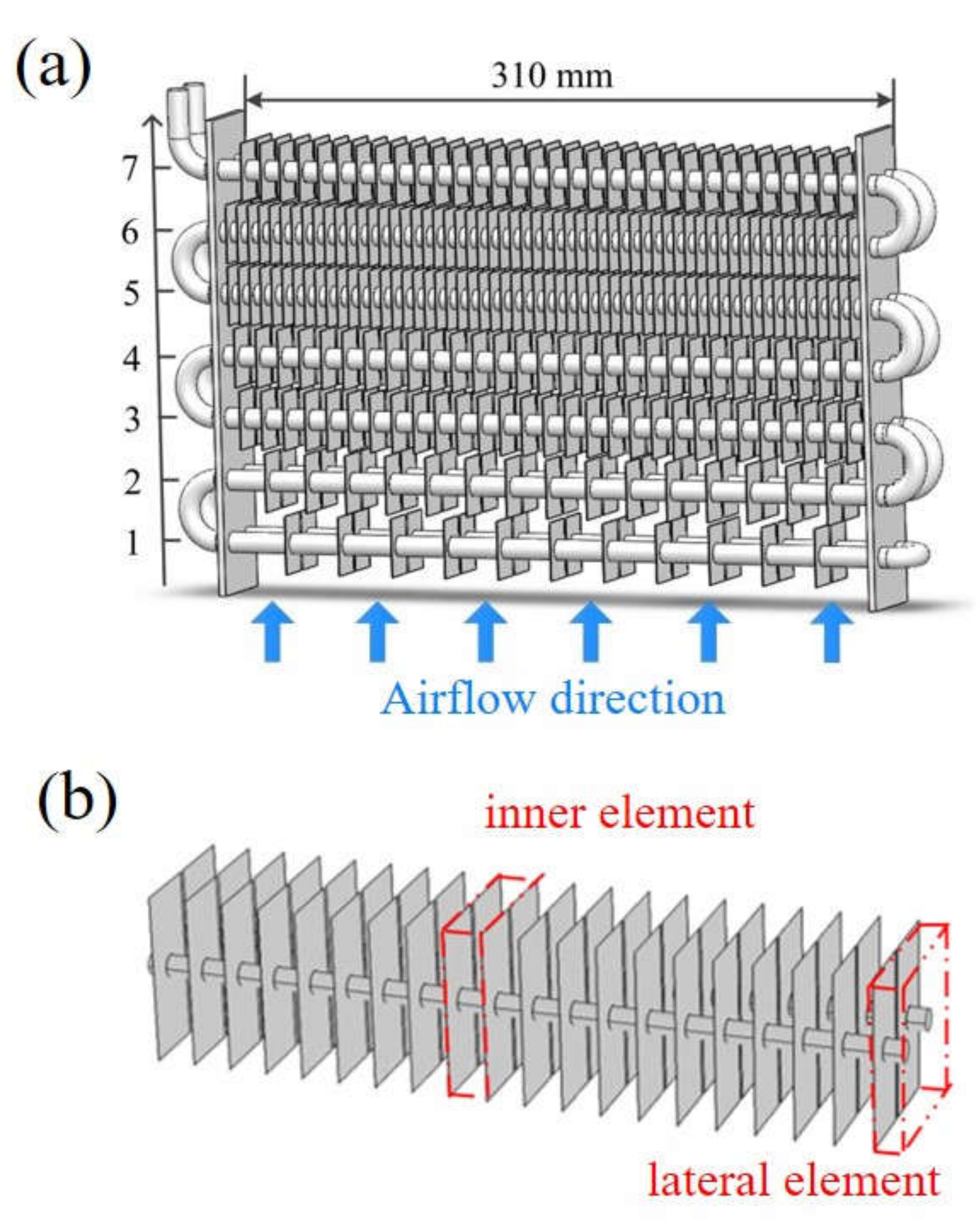
| Rows | 2 | Tubes per row | 7 |
| Fin thickness | 0.15 mm | Fin height | 28 mm |
| Fin width | 60 mm | Tube length | 310 mm |
| Tube out diameter | 8 mm | Tube pitch | 30 mm |
| Row pitch | 30 mm | Fin type | Flat |
| Fins in each row | 11, 15, 29, 29, 58, 58, 33 (from tube 1 to 7 in Figure 6) | ||
| Cases | FZC Return Air | FFC Return Air | VTC Return Air | Evaporator Surface |
|---|---|---|---|---|
| baseline /°C | −13.5 | 0.7 | −10.2 | −21.9 |
| VIP /°C | −12.8 | 2.6 | −10.7 | −20.1 |
| Case | Baseline | VIP |
|---|---|---|
| Experiment/°C | −17.4 | −15.3 |
| Simulation/°C | −17.2 | −15.2 |
© 2020 by the authors. Licensee MDPI, Basel, Switzerland. This article is an open access article distributed under the terms and conditions of the Creative Commons Attribution (CC BY) license (http://creativecommons.org/licenses/by/4.0/).
Share and Cite
Zhao, R.; Qiao, L.; Gao, Z.; Huang, D. Effect of Vacuum Insulation Panels on Energy Consumption and Thermal Load Transfer between Compartments in a Three-Temperature Frost-Free Refrigerator. Energies 2020, 13, 1559. https://doi.org/10.3390/en13071559
Zhao R, Qiao L, Gao Z, Huang D. Effect of Vacuum Insulation Panels on Energy Consumption and Thermal Load Transfer between Compartments in a Three-Temperature Frost-Free Refrigerator. Energies. 2020; 13(7):1559. https://doi.org/10.3390/en13071559
Chicago/Turabian StyleZhao, Rijing, Lin Qiao, Zijian Gao, and Dong Huang. 2020. "Effect of Vacuum Insulation Panels on Energy Consumption and Thermal Load Transfer between Compartments in a Three-Temperature Frost-Free Refrigerator" Energies 13, no. 7: 1559. https://doi.org/10.3390/en13071559
APA StyleZhao, R., Qiao, L., Gao, Z., & Huang, D. (2020). Effect of Vacuum Insulation Panels on Energy Consumption and Thermal Load Transfer between Compartments in a Three-Temperature Frost-Free Refrigerator. Energies, 13(7), 1559. https://doi.org/10.3390/en13071559