Article

Grid-Connected Photovoltaic Systems with Single-Axis Sun Tracker: Case Study for Central Vietnam

1
School of Engineering and Technology, Hue University, Thua Thien Hue 530000, Vietnam
2
Faculty of Thermal, Refrigeration and Construction, Hue Industrial College, Thien Hue 530000, Vietnam
3
Faculty of Electromechanics, Hanoi University of Mining and Geology, 18 Pho Vien, Duc Thang, Bac Tu Liem, Hanoi 100000, Vietnam
4
Center of Excellence for Green Energy and Environmental Nanomaterials (CE@GrEEN), Nguyen Tat Thanh University, Ho Chi Minh City 755414, Vietnam
5
Pyrolysis Technology Research Group, Institute of Tropical Aquaculture and Fisheries (Akuatrop) & Institute of Tropical Biodiversity and Sustainable Development (Bio-D Tropika), Universiti Malaysia Terengganu, Kuala Terengganu 21030, Terengganu, Malaysia
6
Department of Materials Science and Engineering, Korea University, 145 Anam-ro, Seongbuk-gu, Seoul 02841, Korea
7
Department of Materials Science and Engineering, Research Institute of Advanced Materials, Seoul National University, Seoul 08826, Korea
8
Department for Management of Science and Technology Development, Ton Duc Thang University, Ho Chi Minh City 700000, Vietnam
9
Faculty of Applied Sciences, Ton Duc Thang University, Ho Chi Minh City 700000, Vietnam
10
Regional Center of Advanced Technologies and Materials, Department of Physical Chemistry, Faculty of Science, Palacky University, Šlechtitelů 27, 783 71 Olomouc, Czech Republic
11
Institute of Research and Development, Duy Tan University, Da Nang 550000, Vietnam
*
Authors to whom correspondence should be addressed.
Energies 2020, 13(6), 1457; https://doi.org/10.3390/en13061457
Submission received: 3 March 2020 / Revised: 13 March 2020 / Accepted: 17 March 2020 / Published: 20 March 2020
(This article belongs to the Special Issue Photovoltaic Devices)

Abstract

:
Recently, the demand for small grid-connected photovoltaic (PV) systems has been rapidly increasing; this is due to the reduction in the costs of grid-connected storage systems as compared to those of the stand-alone ones. Notably, the performance of the solar tracking system is not only depending on the types but also the region that they are set up and used. To understand how solar tracking systems work globally, we need to know their performance in each country and even the different parts of a country. In this study, two grid-connected PV systems with 250 W solar modules were used to investigate the efficient improvement of a single-axis sun tracking system in Central Vietnam. First, a mechanical tracking device with a linear actuator and a controller was designed and then its performance was comprehensively investigated with a grid-connected PV system. In addition to evaluating the energy gain by the tracking system, this study also considered the energy consumption of the linear actuator with its controller and a small grid-connected PV system; this has generally been omitted in previous works. Experimental results indicate that the total energy consumption of the tracking system was approximately 2–8% of the energy generated by the grid-connected PV system. The maximum overall energy generation was confirmed to have increased by up to 30.3% on a sunny day upon using the proposed tracking system; further, the net energy gain by using the sun tracker was ascertained to be 15.2% in average weather conditions. Based on the success of this work, we will keep experimenting with other parts of Vietnam. Also, we will collaborate with colleagues in other countries to create a guideline for understanding and using the solar tracker regionally and globally.

Graphical Abstract

1. Introduction

In recent years, the demand for renewable and sustainable energy has reached a peak due to the depletion of fossil fuel resources and increasing environmental problems. Various renewable sources such as wind [1,2,3], wave [4,5,6], hydrogen [7,8,9], and solar [10,11,12] energies have been intensively investigated and commercialized. Among these, solar energy is one of the most important sources to harness energy for future applications. It was reported that more than 1.2 × 10⁵ TW of solar energy radiates onto the Earth’s surface, which is far greater than the energy consumption by humans [13]. The utilization of solar energy has been increasing drastically due to the development of science and technologies. For example, the use of solar energy in India has been increased more than eight times within four years from 2014 to 2018 (2.63 GW to 22 GW) [14]. Various strategies have been developed to improve the power conversion efficiency of the photovoltaic (PV) system, including engineering device structure, active materials, and transport materials [15,16,17]. In addition to specifically engineering the intrinsic properties of solar cells, improving their operating conditions is also essential to increase the overall power conversion efficiency of the solar cell systems; for instance, this can be achieved by using a solar concentrator [18,19,20] or a solar tracking system [21,22,23]. Recent studies have demonstrated that the use of a solar tracking device could improve the total energy conversion of a PV system by more than 30–45% [24]. More specifically, the solar tracker is a device that is used to orient the surface of a PV system toward the sun to capture the maximum amount of solar energy possible. Sun trackers can be categorized into two groups, namely: single-axis systems and dual-axis systems [25]. In these systems, mechanical drives can serve as linear actuators, or gearboxes and a DC motor [23]. It should be noted that besides the design of the solar tracker, its performance is also affected by the local climate and the geographic location. The performance of the PV system equipped with a single-axis sun tracking system in Saudi Arabia generates 28–32% more energy as compared to that of a fixed PV system [26]. The improvements effected by sun trackers is approximately 15.13% in Taiwan (single-axis) [27], 20–50% in Europe (single-axis) [28], 30.79% in Turkey (dual-axis) [29], 5.76% in Tunisia (dual-axis and single-axis) [30], and 12–25% in United States of America (single-axis) [31]. Although the sun tracking system could improve the energies gain by the PV modules in many cases, some studies suggest that it is not applicable in hot regions [32]. Thus, before applying the solar tracking system in any region, an intensive investigation should be carried out. To our knowledge, an extensive investigation into the fabrication and operation of solar tracking systems in Vietnam and other Association of Southeast Asian Nations (ASEAN) has been rarely reported [33,34]. To understand the energy gain by the solar tracking system globally, an extensive study in a large area and countries is very important.
In this paper, we designed a single-axis sun tracker and used it in a grid-connected PV system in Central Vietnam (Quang Tri Province). The performance of the sun tracker was then evaluated systematically in various weather conditions. To precisely estimate the improvement in overall power generation by using the tracker, the energy consumption by the tracking system was also taken into account. We found that the energy consumption of the tracker also depends on the local weather conditions, and is higher on sunny days and lower on cloudy or rainy days. This variation generated a fluctuation of approximately 2–8% of the performance of the PV system. After deducting the power lost by the sun tracker, the maximum improvement in power generation on a sunny day was approximately 30.4% as compared to the power generated by a fixed-PV system. Further, the average energy gain by the solar tracker was ascertained to be approximately 15.2%. Based on the data collected from the system under different weather conditions, the performance of the solar tracker has been elucidated in detail in this paper. Therefore, this study facilitates the implementation of sun tracking systems in Vietnam. Moreover, it provides a comprehensive guideline for the design, operation, and investigation of a simple single-axis sun tracking system with a relatively low cost and a high efficiency.

2. Methods and Case Description

2.1. Design of the Sun-Tracking System

2.1.1. Electrical Parameters and Specifications

In this study, two identical systems were used, each including a 250 W solar module 60 (6 × 10) monocrystalline silicon photovoltaic cell in serial connection and 3 bypass diode and a 250 W maximum-power-point-tracking (MPPT) microinverter. The PV modules were mono-crystalline and attributed to the specifications presented in Table 1. Table 2 records the parameters of the MPPT microinverters.
The PV systems were installed in the yard of the Quang Tri Branch of Hue University, Quang Tri, Vietnam (latitude 16 °N, longitude 107 °E). The electricity produced by the PV solar modules was injected directly into the grid.
The proposed sun tracking system consists of a mechanical frame, a linear actuator, an electronic control system, and azimuth positioning sensors. Each azimuth positioning sensor consists of two small solar cells, which were used to test the eastern and western lights on the plane of the solar module. The controller includes a microcontroller that compares the signal from the light sensors and outputs an H-bridge control signal to the linear actuator.

2.1.2. Design of Mechanical Parameters

Two identical grid-connected PV systems were placed on two different mechanical systems. One of them was a sun tracking system and the other was a fixed-tilted PV system, as illustrated in Figure 1. For the fixed PV system, the solar cell was tilted at an angle of 16 °N toward a North–South orientation. The annual optimum tilt angle for the fixed system was found to be approximately equal to the latitude of the location [35,36,37].
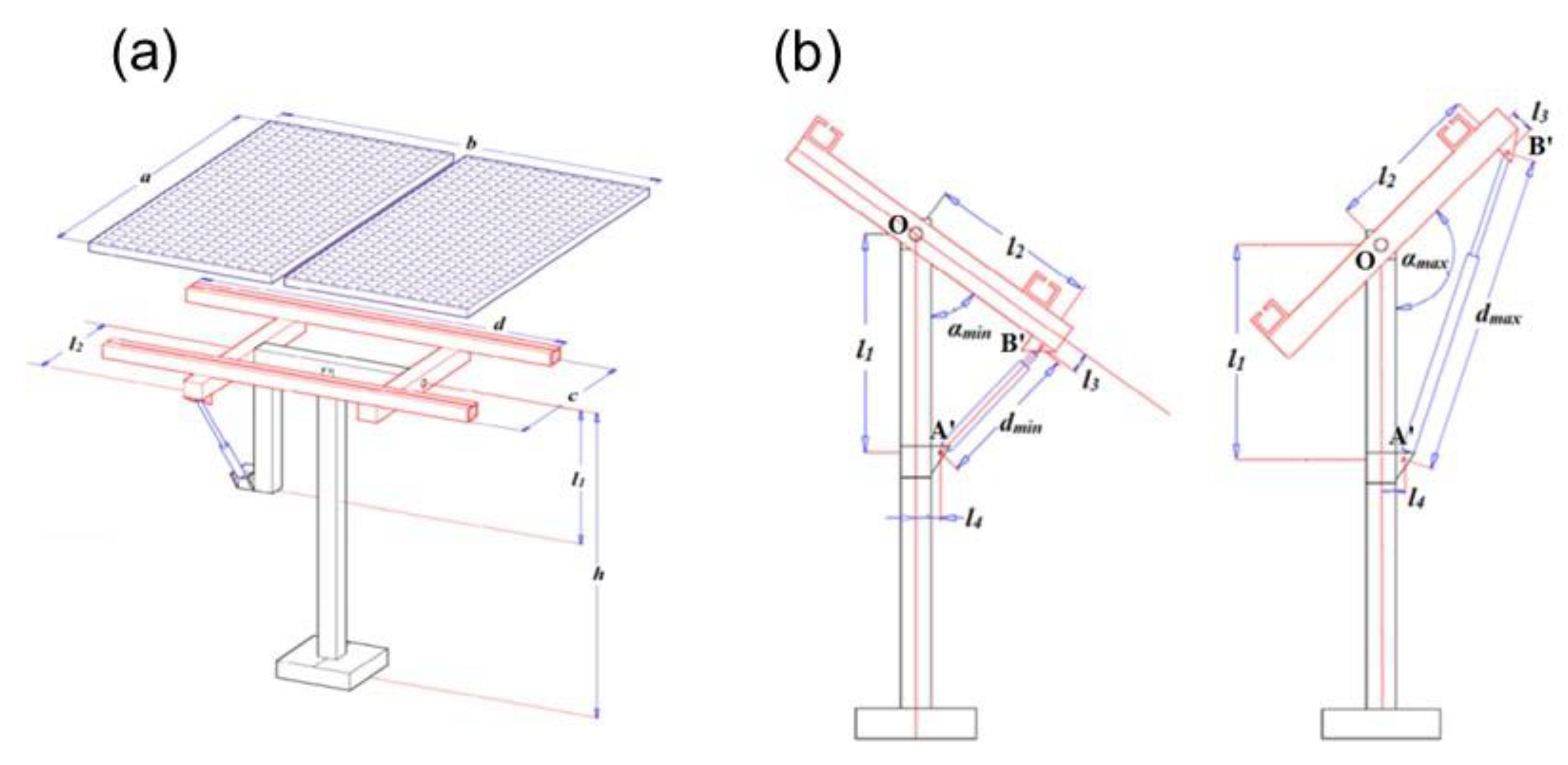
The sun-tracking PV system was designed with the East–West rotation orientation. Figure 2a illustrates the mechanical structure of the proposed single-axis sun tracker, with the size of the solar modules being a × b = 1640 × 1984 mm2 and its weight being m = 34 kg. A rectangular frame of dimension c × d = 1000 × 2000 mm2 and height h = 1500 mm was chosen for the solar modules. To simplify the problem, we chose the following dimensions:
{ l 1 = h / 2 l 2 = c / 2 l 3 = c / 20 l 4 = h / 20
where l1 is the distance from the axis of rotation to the anchor locations of the lower-end actuator; l2 is the distance from the axis of rotation to the anchor locations of the upper-end actuator. l3 is the distance from the axis of the roller bearings, B’, to the frame of the solar modules, and l4 is the distance from the axis of roller bearings, A’, to the pillars.
Figure 2b depicts the sides of the single-axis sun tracker along the axis of rotation. Angle αmin is the initial rotation angle between the support frame and the vertical axis (pillars) and it can be varied between 0° and 90°. To ensure symmetrical operation, the maximum angle is chosen as αmax = 180° − αmin. The selection of the initial rotation angle depends on the requirements of the sun tracking system. The initial rotation angle is inversely proportional to the amount of energy captured by the PV; this is because smaller initial angles enable an increased collection of sunlight during early mornings and late afternoons. However, selecting a low initial angle increases energy loss as more energy is required to execute the rotation.
The next step requires the selection of the parameters of the linear actuator—stroke (Dstr), fully retracted length (dmin), completely extended length (dmax), and force (F). Using geometric transformations and the selected dimensions (1), the optimal dimensions of the linear actuator are calculated as follows:
{ d min 2 = 0.2525 [ h 2 + c 2 2 h c c o s ( α min 11.4 ° ) ] d max 2 = 0.2525 [ h 2 + c 2 2 h c c o s ( 168.6 ° α min ) ] D str = d max d min
The actuator force is calculated by determining the dynamics of the system, and focusing on the crucial relationship between the torques. This system was equipped with three-roller bearings corresponding to the points O, A’, and B’. The friction torque on the normal roller bearings was negligible as compared to the total torque; therefore, it was ignored in this case. The torque around the point O is given as follows [38]:
M qt = M act M e M wind
The actuator torque at the center of rotation of the tracking system was:
M act = F ( c o s ( θ ) . l 3 + s i n ( θ ) . l 2 )
where F is the force of linear actuator; θ is the angle between the plane of the solar modules and the straight line along the linear actuator. The eccentric moment of the tracking system can be given by:
M e = m g . c o s ( α ) . e
where m is the weight of the solar modules; e is the eccentricity, which is the distance from the center of the modules to the center of rotation of the system in a direction perpendicular to the modules, and α is the angle between the solar modules and the vertical axis.
The aerodynamic torque from ambient wind corresponding to the axis of the rotation system [27] can be given by:
M wind = C M . 0.613 . v wind 2 . A . a
where CM is a coefficient that depends on the angle between the wind direction and the solar modules; vwind (m/s) is the wind speed; A(m2) is the surface area of the solar modules, and a (m) is the width of each solar modules.
Typically, during the calculation of the aerodynamic torque, its maximum value is chosen as CM = 0.6 [27]. We assume that the tracking system is activated when the wind is at level 6 (associated with a maximum speed of 13.8 m/s). We also assume that if the rotational part and the solar modules lie on the same plane, then the calculated torque of the rotational part is determined according to theoretical mechanics. In the case of intermittent rotation of the system, the initialization process is repeated several times. Therefore, the equation including the inertia torque is:
M qt = J . ε max = m a 2 12 ε max
where εmax (rad/s2) is the angular acceleration of the system during initialization; J (Kg.m2) is the moment of inertia of the rotational part and the solar modules, and m (kg) is the weight and a (m) is the width of the solar modules.
Choosing an angular acceleration of 1 rad/s2, we calculate the force of the linear actuator. Table 3 records the dependence of dimensions and the maximum actuator force (Fmax) on the initial rotation angle.
In this paper, the proposed initial rotation angle is 60°. Based on the data presented in Table 3, linear actuator type HF-TGA-A 450-12-4 was selected and it comprised a stroke of 450 mm, an input voltage of 12VDC, 4 mm/s of speed, 1500 N of force (maximum load), a proximity sensor, and fully retracted and extended lengths of 555 and 1005 mm, respectively. In addition, to control the linear actuator, we used the single-axis solar tracking controller WST03-5 and the light sensor from two PV cells.
After designing the tracking system with a rotation angle between 55° and 125°, the system performed satisfactorily on under the wind speed of 6.6–8.3 m/s [29].

2.2. Case Study

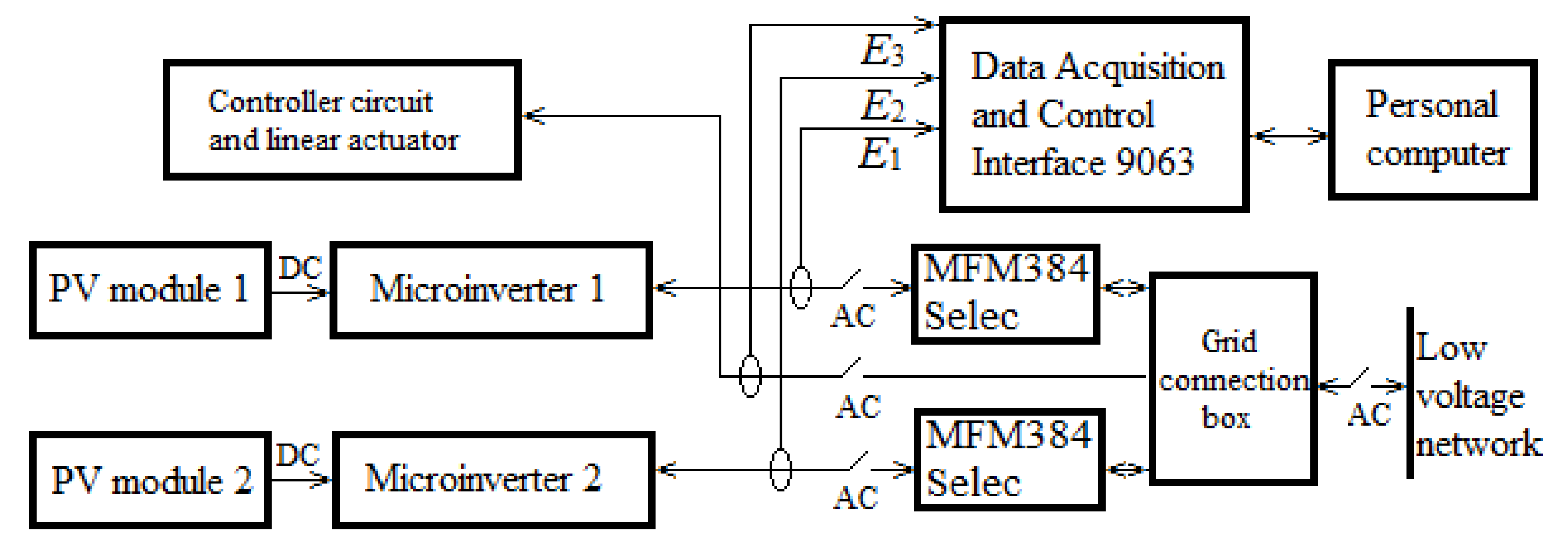
Active power and energy were measured using the Data Acquisition and Control Interface (DACI) 9063 device of Labvolt company. The block diagram of the measurement system is presented in Figure 3. To measure the alternating current and voltage from the grid-connected PV system with sun tracking, the following inputs were employed: The insulated current input I1 with an accuracy of 1% at a range of −4 to +4 A, and the insulated voltage input E1 with an accuracy of 1% at a range of 800 A. To measure the alternating current and voltage from grid-connected PV system without sun tracking the following inputs were employed: the insulated current input I2 with an accuracy of 1% at a range of −4 to +4 A, and the insulated voltage input E2 with an accuracy of 1% at a range of 800 A. To measure the consumption of alternating current and voltage by the controller circuit and linear actuator, the following inputs were employed: The insulated current input I3 with an accuracy of 1% at a range of −4 to +4 A, and the insulated voltage input E3 with an accuracy of 1% at the range of 800 A.
Metering and Data Table (computer-based instruments) of the 3.17.01 LVDAC-EMS software on personal computer through a serial interface was used to calculate and display current, voltage, active power, and the energy values from DACI 9063. The data-recording interval was 10 s. The data sets were processed on the Origin software to draw the desired graphs.
Further, the MFM384 Selec multifunction meter was used to store the values of energy generated by the grid-connected PV systems. The accuracies of the parameters of the MFM384 Selec multifunction meter are as follows: Voltage is ±0.5% of the full scale, the current is ±0.5% of the full scale, and the active power is 1%.
DACI 9063 of Labvolt company and MFM384 Selec multifunction meter were used in the electrical laboratory of Quang Tri Branch of Hue University.

3. Result and Discussion

3.1. Evaluation of Energy Consumption by the Sun Tracker

To compare the efficiency of the two systems, the measurement of the daily energy generated by the system with sun tracking was required (E1); further, the energy generated by the system without sun tracking (E2) and the total power consumption of the controller circuit and the linear actuator was also necessitated (E3).
The average improvement in energy generation can be calculated as a percentage using the following equation:
η = E 1 E 2 E 2 100
More precisely, by including the energy consumed by the actuator and the controller, the overall efficiency of the sun tracking system compared to the fixed one can be given by:
η * = E 1 E 2 E 3 E 2 100
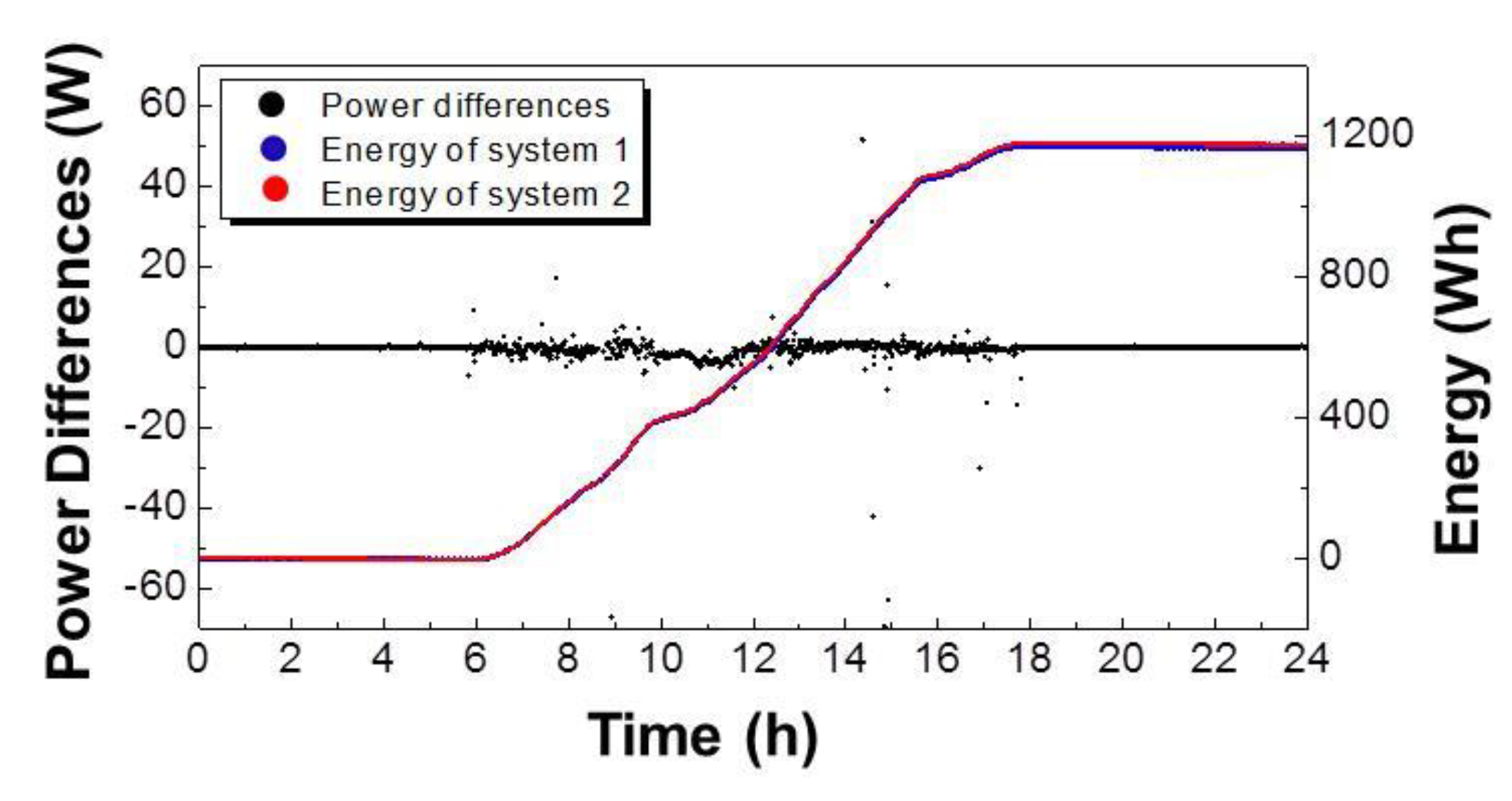
Both systems used identical solar modules and MPPT microinverters. The power and energy generated by the two systems were measured at the same time under the same conditions. The experiment was carried out on a sunny day. The results of the measurements are depicted in Figure 4.
The average difference in power generated by the two systems was observed to be approximately 0.38 W and the energies generated by the two systems were almost the same (1166.8 Wh for system 1, 1175.6 Wh for system 2). The average energy difference obtained during the day was approximately 0.7%, which is negligible. Therefore, the two grid-connected PV systems can be considered to be almost identical and can be used to check the effectiveness of sun tracking. This result indicates that the prepared systems are reliable for studying the performance of the sun tracking system. Following this step, we gathered measurements from June 2018 to September 2018 (3 months) and selected sunny, cloudy and rainy days to be the three specific case studies.
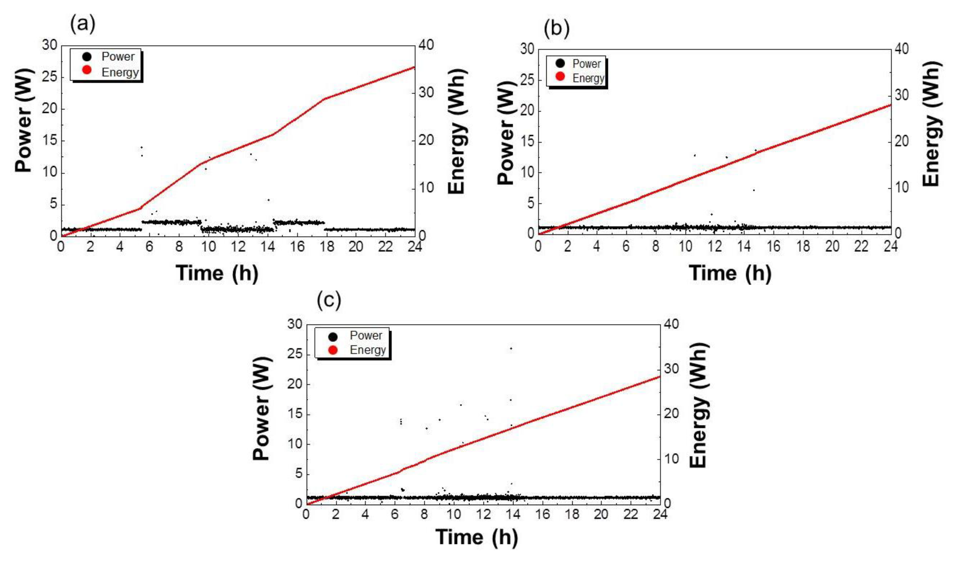
First, the power and energy consumptions were evaluated and are depicted in Figure 5. It is obvious that on a sunny day the tracking system worked more efficiently, and thus consumed more energy. However, there were no distinguishable differences between the same on the cloudy and rainy days. Typically, the energy needed by the tracking system on a sunny day was 35.6, 28.1, and 28.5 Wh, respectively. These values were further used to evaluate the overall improvement in energy generation by the sun tracking system.

3.2. Performance of the Sun Tracking System on a Sunny Day

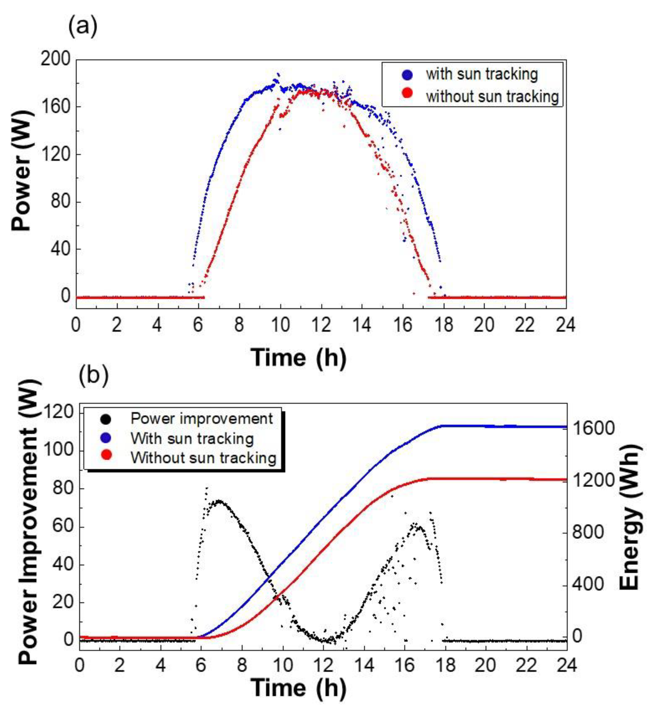
The electrical power generated by both systems recorded on a sunny day is presented in Figure 6. On the sunny day when the experiment was carried out, the temperature was 29 °C until 8 AM. Then the temperature rose to 39 °C around 11:30 and stable until 2 PM. After that, the temperature reduced steadily to 29 °C until 6 PM. The sky on this day is clear with no clouds that interfere with the performance of the PV system. The power generated by both the systems increased from sunrise until midday and then reduced until the sunset. Fluctuations were noticed in the power generated by both systems due to shadows caused by the intermittent heavy clouds. During this period, only a small amount of solar radiation coincided with the solar modules and; therefore, both systems produced approximately the same amount of power regardless of the incidence angle. A significant difference in power generation between the systems was noticed from sunrise until 11:30 AM and from 02:00 PM until sunset (Figure 6a). During the noon period, from 11:30 AM to 02:00 PM, both systems possessed the same azimuth and angle to the sun; therefore, the power generated by the two systems was quite similar. The average difference between the daily energies generated by grid-connected PV systems with and without sun tracking was observed to be 33.3%. After considering the consumption of the tracker, the overall efficiency was ascertained to be 30.3%. The energies generated by a PV system with and without a sun tracker were 1555 and 1277 Wh, respectively (Figure 6b).

3.3. Performance of the Sun Tracking System on a Cloudy Day

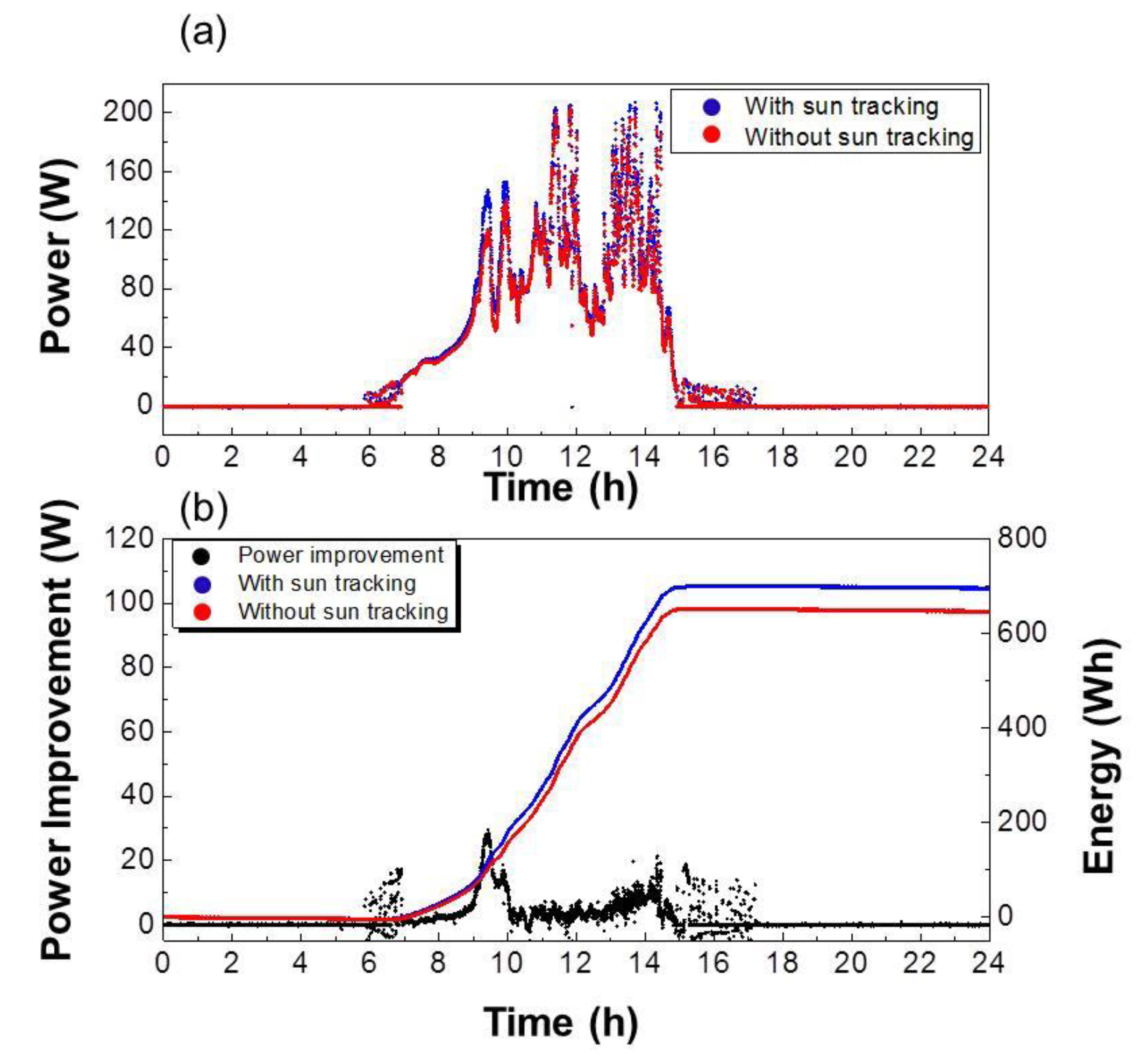
The power generated by both systems on a cloudy day is presented in Figure 7a. On this day, the temperature was 27, 36 and 28 °C from 8 AM to 11:30 to 2 PM and 6 PM, respectively. The sun was partially hindered by clouds. As is apparent from the figure, the power generated by both systems was almost identical. After 3.00 PM, the sky started to become heavily overcast, and thus both systems stopped working and the power generated during this period approached zero. After subtracting the energy consumed by the sun tracker, the overall energy gain was ascertained to be only 3.2%. The total energies generated by a PV system with and without a sun tracker were 695 and 646 Wh, respectively (Figure 7b).

3.4. Performance of the Sun Tracking System on a Rainy Day

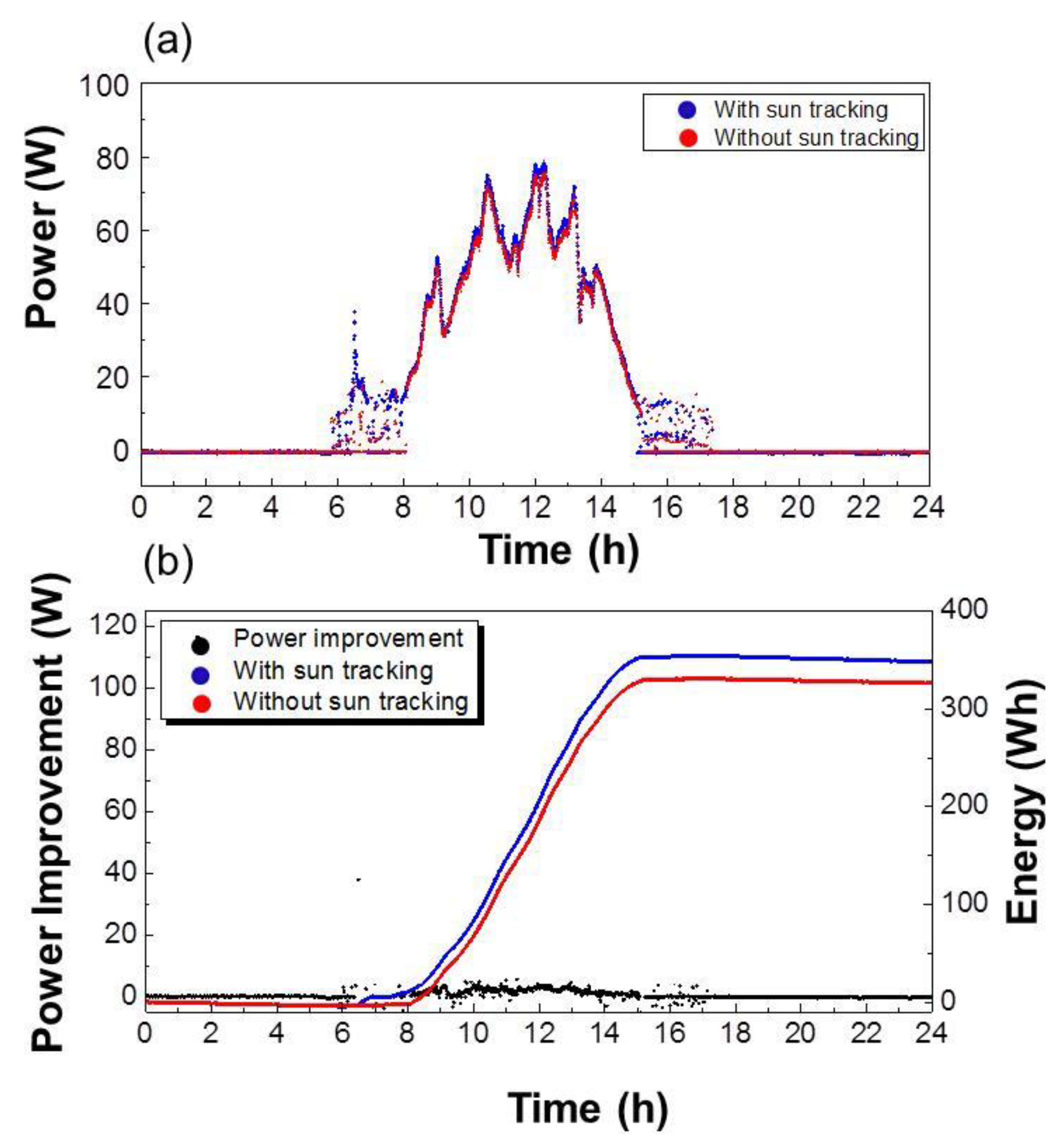
The power generation of the PV system on a rainy day is depicted in Figure 8a. On the whole rainy day, the temperature fluctuated around 25 to 29 °C from the morning to the afternoon. The sun radiation was blocked by clouds most of the time. Because of the heavy cloud and rain that blocked the solar radiation to be incident on both the systems, an extremely low amount of power was generated. The maximum output power of the system was approximately 78 W at noon. The daily energy gain by the system with the sun tracker was 347.9 Wh, and the daily energy gain by the system without the sun tracker was 326.0 Wh (Figure 8b). The daily energy consumption by the actuator and the controller was 28.5 W. It should be noted that during rainy days, the probability of the actuators and controllers to work was less than that on sunny days. Although the day was overcast, the difference between the average daily energies generated by the grid-connected PV system with and without sun tracking was still noticeable at a power difference of 6.7%. Unfortunately, the increase in the generated energy was less than the amount of energy consumed by the tracking system; thus, the overall efficiency was observed to be −2%.
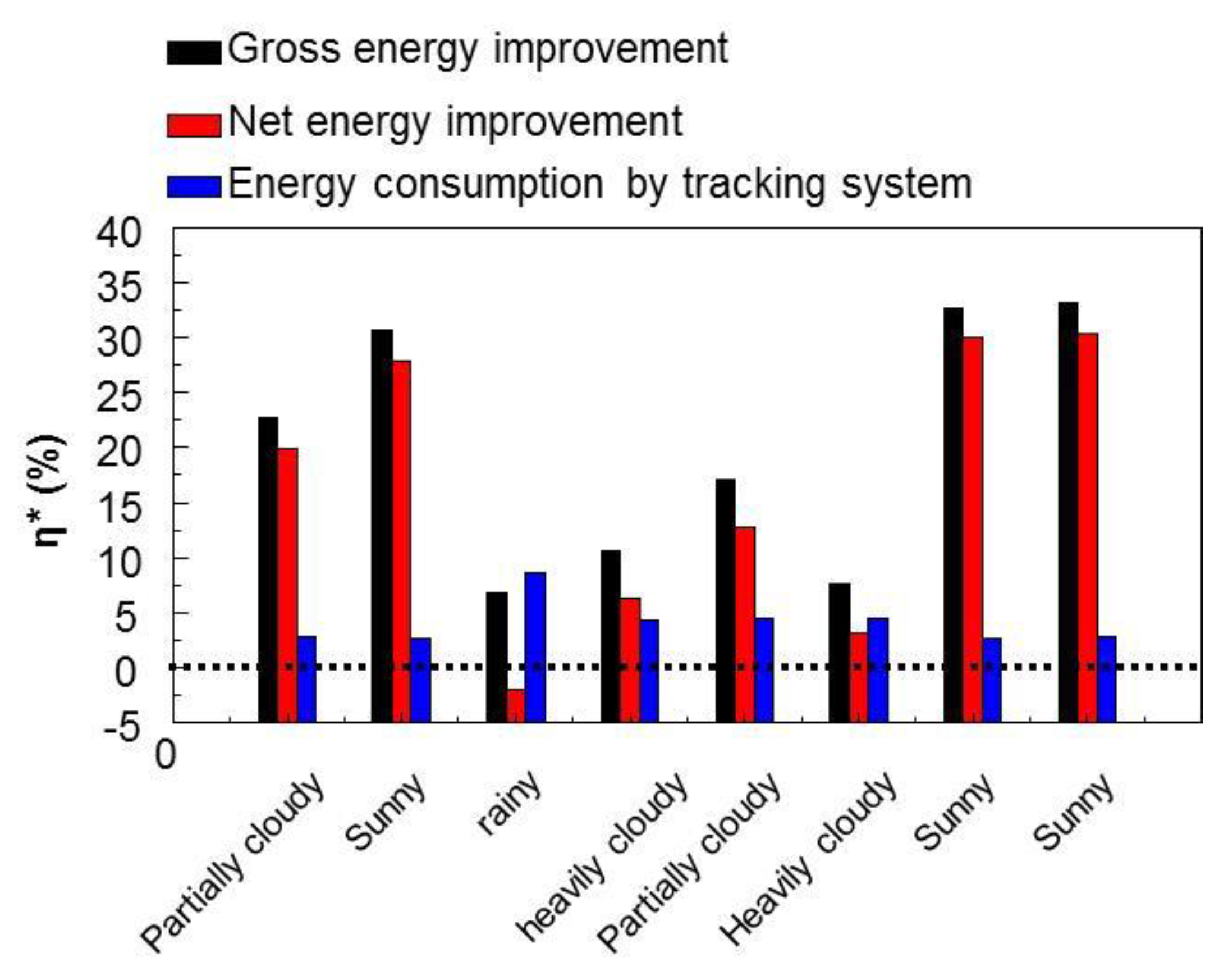
Energy enhancement of the tracking system under different weather conditions is depicted in Figure 9. As is apparent from the figure, the power of the PV system was improved in most cases; however, this not true for days with excessively heavy rains. The net energy improvement recorded was 15.2%, which was evaluated continuously for 90 d of experiment regardless of the weather conditions. This result verifies the important role of sun trackers in grid-connected PV systems in Central Vietnam.

4. Conclusions

This study analyzes the improved efficiency of grid-connected photovoltaic systems by using a single-axis sun tracker in Central Vietnam. Grid-connected 250 W PV systems with and without single-axis sun-tracking were designed and installed; further, their performances were investigated. The results demonstrated a significant difference in power generation between the two systems, especially during early mornings and late afternoons. At noon, the power generated by both systems was almost identical. On a sunny day, the maximum energy generated by the PV with the sun tracker was 1732 Wh, and the average energy consumption of the controller and the linear actuator was 35 Wh. The overall efficiency of the grid-connected PV system was improved by up to 30.3% and 15.2% in sunny and average weather conditions, respectively; this was achieved by using a single-axis sun tracker. Therefore, this work indicates that a simple hand-made sun tracing system could improve the performance of solar plants effectively. This work also demonstrated that the energy consumption of the sun tracker is too small compared to the energies gain, thus it can be operated all the time of years without turning off. To fully understand the performance of sun trackers globally, more investigations in other regions in Vietnam and other countries are very necessary.

Author Contributions

Conceptualization, X.C.N.; methodology, X.C.N., Q.V.L. and V.-H.N.; formal analysis, T.H.N., N.Y.D., D.M.N., D.-V.N.V., S.S.L., D.H., M.S.; investigation, X.C.N.; writing—review and editing, X.C.N., V.-H.N., R.S.V., S.Y.K., and Q.V.L.; supervision, V.-H.N., R.S.V., S.Y.K., and Q.V.L.; project administration, X.C.N. and Q.V.L.; funding acquisition, X.C.N., and S.Y.K. All authors have read and agreed to the published version of the manuscript.

Funding

This work was supported by a National Research Foundation of Korea (NRF) grant funded by the Korean government (MSIP) [grant numbers 2017K1A3A1A67014432, 2018R1A4A1022647] and by a grant (No. DHH2017-13-03) from Hue University.

Conflicts of Interest

The authors declare no conflicts of interest.

Abbreviations

NomenclatureAbbreviationUnit
Peak maximum powerPmpWp
Open-circuit voltageVocV
Short-circuit currentIscA
Peak maximum voltageVmpV
Peak maximum currentImpA
Input voltageUinVDC
Output voltageUoutVAC
Total harmonic distortionTHD%
Width of solar panelamm
Length of solar panelbmm
WeightmKg
Dimension 1 of rectangular framecmm
Dimension 2 of rectangular framedmm
Height of rectangular framehmm
Distance from the axis of rotation to the anchor locations of the lower-end actuator;l1mm
Distance from the axis of rotation to the anchor locations of the upper-end actuatorl2mm
Distance from the axis of the roller bearings, B’, to the frame of the solar panelsl3mm
Distance from the axis of roller bearings, A’, to the pillarsl4mm
Initial rotation angle between the support frame and the vertical axis (pillars)αmin°
Maximum angleαmax°
Stroke of linear actuatorDstrmm
Fully retracted length of linear actuatordminmm
Completely extended length of linear actuatordmaxmm
Force of linear actuatorFN
Actuator torqueMactNm
Angle between the plane of the solar panel and the straight line along the linear actuatorθ°
Eccentric momentMeNm
The eccentricityem
Angle between the solar panel and the vertical axisα°
Aerodynamic torqueMwindNm
Coefficient that depends on the angle between the wind direction and the solar panelCM
Wind speedvwindm/s
Surface area of the solar panelAm2
Inertia torqueMqtNm
Angular accelerationεmaxrad/s2
Moment of inertia of the rotational part and the solar panelsJKg.m2
Daily energy generated by the system with sun trackingE1Wh
The energy generated by the system without sun trackingE2Wh
The total power consumption of the controller circuit and the linear actuatorE3Wh
Average improvementη%
Overall efficiencyη*%

References

  1. Faturay, F.; Vunnava, V.S.G.; Lenzen, M.; Singh, S. Using a new USA multi-region input output (MRIO) model for assessing economic and energy impacts of wind energy expansion in USA. Appl. Energy 2020, 261, 114141. [Google Scholar] [CrossRef]
  2. Emeksiz, C.; Demirci, B. The determination of offshore wind energy potential of Turkey by using novelty hybrid site selection method. Sustain. Energy Technol. Assess. 2019, 36, 100562. [Google Scholar] [CrossRef]
  3. Zhao, L.-C.; Zou, H.-X.; Yan, G.; Liu, F.-R.; Tan, T.; Wei, K.-X.; Zhang, W.-M. Magnetic coupling and flextensional amplification mechanisms for high-robustness ambient wind energy harvesting. Energy Convers. Manage. 2019, 201, 112166. [Google Scholar] [CrossRef]
  4. Zhang, H.; Zhou, B.; Vogel, C.; Willden, R.; Zang, J.; Zhang, L. Hydrodynamic performance of a floating breakwater as an oscillating-buoy type wave energy converter. Appl. Energy 2020, 257, 113996. [Google Scholar] [CrossRef]
  5. Xu, X.; Robertson, B.; Buckham, B. A techno-economic approach to wave energy resource assessment and development site identification. Appl. Energy 2020, 260, 114317. [Google Scholar] [CrossRef]
  6. Cuttler, M.V.W.; Hansen, J.E.; Lowe, R.J. Seasonal and interannual variability of the wave climate at a wave energy hotspot off the southwestern coast of Australia. Renew. Energy 2020, 146, 2337–2350. [Google Scholar] [CrossRef]
  7. Maggio, G.; Nicita, A.; Squadrito, G. How the hydrogen production from RES could change energy and fuel markets: A review of recent literature. Int. J. Hydrogen Energy 2019, 44, 11371–11384. [Google Scholar] [CrossRef]
  8. Fonseca, J.D.; Camargo, M.; Commenge, J.-M.; Falk, L.; Gil, I.D. Trends in design of distributed energy systems using hydrogen as energy vector: A systematic literature review. Int. J. Hydrogen Energy 2019, 44, 9486–9504. [Google Scholar] [CrossRef]
  9. Chapman, A.; Itaoka, K.; Hirose, K.; Davidson, F.T.; Nagasawa, K.; Lloyd, A.C.; Webber, M.E.; Kurban, Z.; Managi, S.; Tamaki, T.; et al. A review of four case studies assessing the potential for hydrogen penetration of the future energy system. Int. J. Hydrogen Energy 2019, 44, 6371–6382. [Google Scholar] [CrossRef]
  10. Zhang, Y.; Ren, J.; Pu, Y.; Wang, P. Solar energy potential assessment: A framework to integrate geographic, technological, and economic indices for a potential analysis. Renew. Energy 2020, 149, 577–586. [Google Scholar] [CrossRef]
  11. Lobaccaro, G.; Croce, S.; Lindkvist, C.; Munari Probst, M.C.; Scognamiglio, A.; Dahlberg, J.; Lundgren, M.; Wall, M. A cross-country perspective on solar energy in urban planning: Lessons learned from international case studies. Renew. Sust. Energ. Rev. 2019, 108, 209–237. [Google Scholar] [CrossRef]
  12. Kaya, O.; Klepacka, A.M.; Florkowski, W.J. Achieving renewable energy, climate, and air quality policy goals: Rural residential investment in solar panel. J. Environ. Manage. 2019, 248, 109309. [Google Scholar] [CrossRef] [PubMed]
  13. Li, G.; Shittu, S.; Diallo, T.M.O.; Yu, M.; Zhao, X.; Ji, J. A review of solar photovoltaic-thermoelectric hybrid system for electricity generation. Energy 2018, 158, 41–58. [Google Scholar] [CrossRef]
  14. Awasthi, A.; Shukla, A.K.; SR., M.M.; Dondariya, C.; Shukla, K.N.; Porwal, D.; Richhariya, G. Review on sun tracking technology in solar PV system. Energy Rep. 2020, 6, 392–405. [Google Scholar] [CrossRef]
  15. Ghosh, B.K.; Weoi, C.N.J.; Islam, A.; Ghosh, S.K. Recent progress in Si hetero-junction solar cell: A comprehensive review. Renew. Sust. Energ. Rev. 2018, 82, 1990–2004. [Google Scholar] [CrossRef]
  16. Parida, B.; Yoon, S.; Jeong, S.M.; Cho, J.S.; Kim, J.-K.; Kang, D.-W. Recent progress on cesium lead/tin halide-based inorganic perovskites for stable and efficient solar cells: A review. Sol. Energy Mater. Sol. Cells 2020, 204, 110212. [Google Scholar] [CrossRef]
  17. Mohamad, A.A. Physical properties of quasi-solid-state polymer electrolytes for dye-sensitised solar cells: A characterisation review. Sol. Energy 2019, 190, 434–452. [Google Scholar] [CrossRef]
  18. Li, G.; Xuan, Q.; Akram, M.W.; Golizadeh Akhlaghi, Y.; Liu, H.; Shittu, S. Building integrated solar concentrating systems: A review. Appl. Energy 2020, 260, 114288. [Google Scholar] [CrossRef]
  19. Wang, J.; Yuan, Y.; Zhu, H.; Cai, T.; Fang, Y.; Chen, O. Three-dimensional macroporous photonic crystal enhanced photon collection for quantum dot-based luminescent solar concentrator. Nano Energy 2019, 67, 104217. [Google Scholar] [CrossRef]
  20. Delgado-Sanchez, J.-M. Luminescent solar concentrators: Photo-stability analysis and long-term perspectives. Sol. Energy Mater. Sol. Cells 2019, 202, 110134. [Google Scholar] [CrossRef]
  21. Hafez, A.Z.; Yousef, A.M.; Harag, N.M. Solar tracking systems: Technologies and trackers drive types – A review. Renew. Sust. Energ. Rev. 2018, 91, 754–782. [Google Scholar] [CrossRef]
  22. Sumathi, V.; Jayapragash, R.; Bakshi, A.; Kumar Akella, P. Solar tracking methods to maximize PV system output – A review of the methods adopted in recent decade. Renew. Sust. Energ. Rev. 2017, 74, 130–138. [Google Scholar] [CrossRef]
  23. Al-Rousan, N.; Isa, N.A.M.; Desa, M.K.M. Advances in solar photovoltaic tracking systems: A review. Renew. Sust. Energ. Rev. 2018, 82, 2548–2569. [Google Scholar] [CrossRef]
  24. Abu-Khader, M.M.; Badran, O.O.; Abdallah, S. Evaluating multi-axes sun-tracking system at different modes of operation in Jordan. Renew. Sust. Energ. Rev. 2008, 12, 864–873. [Google Scholar] [CrossRef]
  25. Nsengiyumva, W.; Chen, S.G.; Hu, L.; Chen, X. Recent advancements and challenges in Solar Tracking Systems (STS): A review. Renew. Sust. Energ. Rev. 2018, 81, 250–279. [Google Scholar] [CrossRef]
  26. Almarshoud, A.F. Performance of solar resources in Saudi Arabia. Renew. Sust. Energ. Rev. 2016, 66, 694–701. [Google Scholar] [CrossRef]
  27. Kuo, K.-C.; Liao, M.-S.; Wang, J.-C.; Lee, Y.-C.; Huang, C.-K.; Chou, C.-Y.; Liu, C.-Y.; Hsu, H.-H.; Chen, P.-H.; Jiang, J.-A. Comprehensive assessment of the long-term energy harvest capabilities for PV systems with different tilt angles: Case study in Taiwan. Renew. Sust. Energ. Rev. 2018, 97, 74–89. [Google Scholar] [CrossRef]
  28. Huld, T.; Cebecauer, T.; Šúri, M.; Dunlop, E.D. Analysis of one-axis tracking strategies for PV systems in Europe. Prog. Photovoltaics 2010, 18, 183–194. [Google Scholar] [CrossRef]
  29. Eke, R.; Senturk, A. Performance comparison of a double-axis sun tracking versus fixed PV system. Sol. Energy 2012, 86, 2665–2672. [Google Scholar] [CrossRef]
  30. Maatallah, T.; El Alimi, S.; Nassrallah, S.B. Performance modeling and investigation of fixed, single and dual-axis tracking photovoltaic panel in Monastir city, Tunisia. Renew. Sust. Energ. Rev. 2011, 15, 4053–4066. [Google Scholar] [CrossRef]
  31. Drury, E.; Lopez, A.; Denholm, P.; Margolis, R. Relative performance of tracking versus fixed tilt photovoltaic systems in the USA. Prog. Photovoltaics 2014, 22, 1302–1315. [Google Scholar] [CrossRef]
  32. Eldin, S.A.S.; Abd-Elhady, M.S.; Kandil, H.A. Feasibility of solar tracking systems for PV panels in hot and cold regions. Renew. Energy 2016, 85, 228–233. [Google Scholar] [CrossRef]
  33. Kies, A.; Schyska, B.; Thanh Viet, D.; von Bremen, L.; Heinemann, D.; Schramm, S. Large-Scale Integration of Renewable Power Sources into the Vietnamese Power System. Energy Procedia 2017, 125, 207–213. [Google Scholar] [CrossRef]
  34. Baulch, B.; Duong Do, T.; Le, T.-H. Constraints to the uptake of solar home systems in Ho Chi Minh City and some proposals for improvement. Renew. Energy 2018, 118, 245–256. [Google Scholar] [CrossRef] [Green Version]
  35. Al-Mohamad, A. Efficiency improvements of photo-voltaic panels using a Sun-tracking system. Appl. Energy 2004, 79, 345–354. [Google Scholar] [CrossRef]
  36. Abdallah, S. The effect of using sun tracking systems on the voltage–current characteristics and power generation of flat plate photovoltaics. Energy Convers. Manag. 2004, 45, 1671–1679. [Google Scholar] [CrossRef]
  37. Benghanem, M. Optimization of tilt angle for solar panel: Case study for Madinah, Saudi Arabia. Appl. Energy 2011, 88, 1427–1433. [Google Scholar] [CrossRef]
  38. Gorjian, S.; Ghobadian, B.; Tavakkoli Hashjin, T.; Banakar, A. Experimental performance evaluation of a stand-alone point-focus parabolic solar still. Desalination 2014, 352, 1–17. [Google Scholar] [CrossRef]
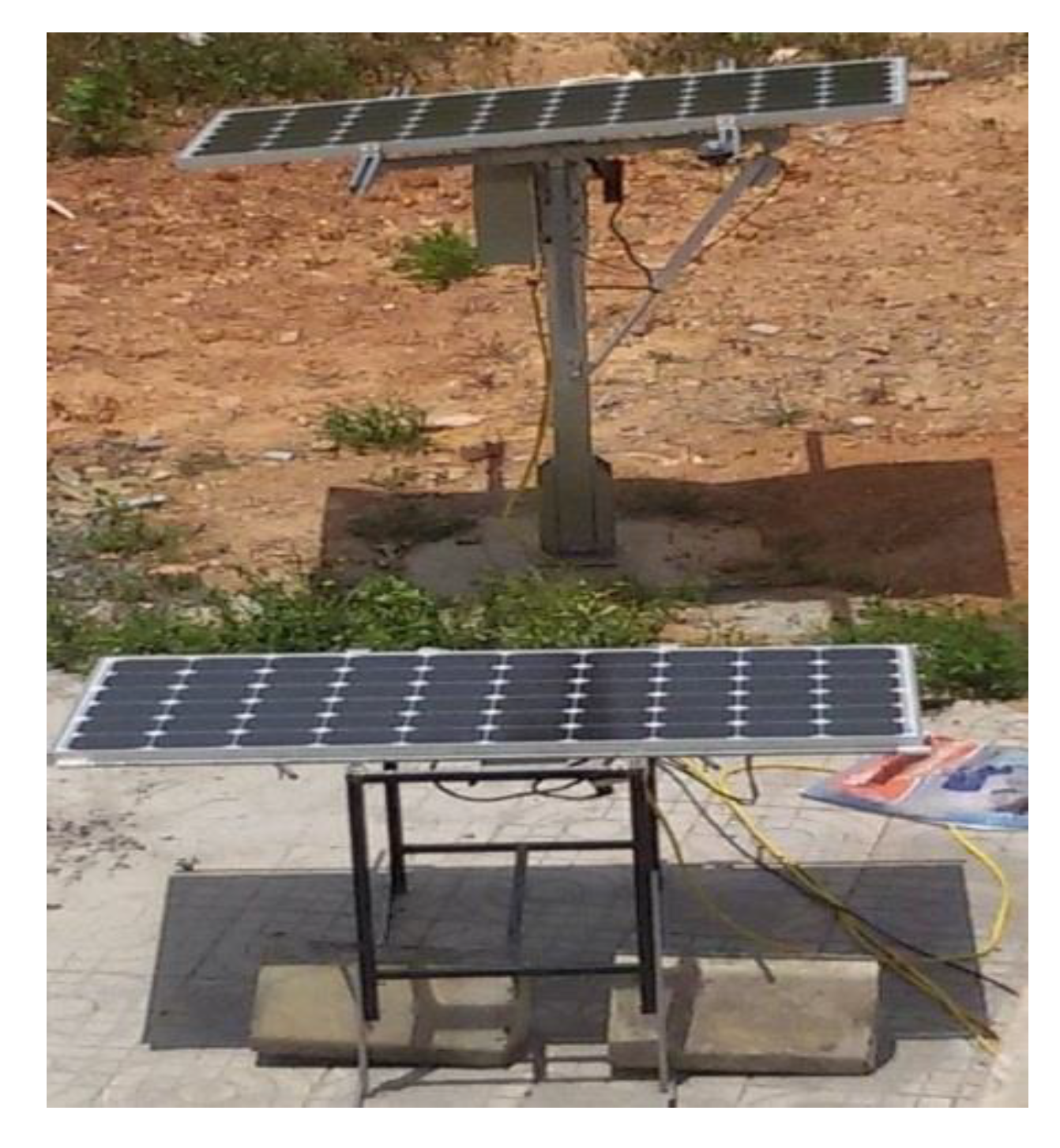
Figure 1. Sun tracking and fixed-tilted PV systems.
Energies 13 01457 g001
Figure 2. Mechanical model of the single-axis sun tracker. (a) General view; (b) view along the axis of rotation.
Energies 13 01457 g002
Figure 3. Block diagram of the measurement system (MFM: multifunction meter).
Energies 13 01457 g003
Figure 4. Differences in power and energy generated by the two systems under the same conditions.
Energies 13 01457 g004
Figure 5. Power and energy consumption of the tracking system on (a) a sunny day, (b) a cloudy day, (c) a rainy day.
Energies 13 01457 g005
Figure 6. (a) Power generation and (b) power improvement and energy gain on a sunny day.
Energies 13 01457 g006
Figure 7. (a) Power generation and (b) power improvement and energy gain on a cloudy day.
Energies 13 01457 g007
Figure 8. (a) Power generation and (b) power improvement and energy gain on a rainy day.
Energies 13 01457 g008
Figure 9. Energy improvement of the sun tracker under different weather conditions.
Energies 13 01457 g009
Table 1. PV electrical specification.
PropertiesValue
Peak maximum power Pmp (Wp)250
Open-circuit voltage Voc(V)37.4
Short-circuit current Isc (A)8.83
Peak maximum voltage Vmp (V)30.0
Peak maximum current Imp (A)8.33
Table 2. Parameters of microinverters.
PropertiesValue
Peak maximum power Pmp (W)250
Input voltage Uin (VDC)22–45
Output voltage Uout (VAC)190–260
Output frequency50/60 (auto)
Total harmonic distortion TDH<3%
Steady output efficiency>90%
MPPT range (VDC)28–36
Power factor>97%
Table 3. Dependence of dimensions and actuator force on the initial rotation angle αmin.
αmin (°)dmin
(mm)
dmax
(mm)
Dstr
(mm)
Fmax
(N)
0375135097510,000
1535413239695701
3041012758652847
4551612066901623
6064311204771332
7577410172431159
9090190101052