Article

Towards Developing an Automated Faults Characterisation Framework for Rotating Machines. Part 1: Rotor-Related Faults

by
Akilu Yunusa-Kaltungo
1,* and
Ruifeng Cao
1,2
1
Department of Mechanical, Aerospace and Civil Engineering, University of Manchester, Manchester M13 9PL, UK
2
School of Mechanical and Vehicle Engineering, Taiyuan University of Technology, Taiyuan 030024, China
*
Author to whom correspondence should be addressed.
Energies 2020, 13(6), 1394; https://doi.org/10.3390/en13061394
Submission received: 14 January 2020 / Revised: 2 March 2020 / Accepted: 12 March 2020 / Published: 17 March 2020
(This article belongs to the Section K: State-of-the-Art Energy Related Technologies)

Abstract

:
Rotating machines are pivotal to the achievement of core operational objectives within various industries. Recent drives for developing smart systems coupled with the significant advancements in computational technologies have immensely increased the complexity of this group of critical physical industrial assets (PIAs). Vibration-based techniques have contributed significantly towards understanding the failure modes of rotating machines and their associated components. However, the very large data requirements attributable to routine vibration-based fault diagnosis at multiple measurement locations has led to the quest for alternative approaches that possess the capability to reduce faults diagnosis downtime. Initiatives aimed at rationalising vibration-based condition monitoring data in order to just retain information that offer maximum variability includes the combination of coherent composite spectrum (CCS) and principal components analysis (PCA) for rotor-related faults diagnosis. While there is no doubt about the potentials of this approach, especially that it is independent of the number of measurement locations and foundation types, its over-reliance on manual classification made it prone to human subjectivity and lack of repeatability. The current study therefore aims to further enhance existing CCS capability in two facets—(1) exploration of the possibility of automating the process by testing its compatibility with various machine learning techniques (2) incorporating spectrum energy as a novel feature. It was observed that artificial neural networks (ANN) offered the most accurate and consistent classification outcomes under all considered scenarios, which demonstrates immense opportunity for automating the process. The paper describes computational approaches, signal processing parameters and experiments used for generating the analysed vibration data.

1. Introduction

The past few decades have been characterised by very significant population growths (i.e., from 2.53 billion in 1950 to 7.16 billion in 2011 and predicted to reach 14.4 billion within the next 6 decades) across the world [1]. As a direct consequence of this unprecedented growth, the global primary energy consumption has correspondingly risen from 3701 Mtoe in the mid-1960s to approximately 13511 Mtoe in 2017 [1,2]. Besides the strains exerted by current energy demands on existing energy generation and distribution systems across the world, the sustainability of present scenarios is questionable, owing to the rapid depletion of primary energy resources such as crude oil, coal, and natural gas (estimated to be completely depleted in 50.2, 52.6 and 134 years, respectively) [2]. Additionally, the global upsurge in initiatives aimed at shifting the energy paradigm towards renewable and more sustainable sources is gradually increasing the attention on alternative sources including wind, solar, etc. However, irrespective of energy generation source, the existence of rotating machines is almost inevitable along the entire supply chain, owing to their versatility and criticality. For instance, wind turbines are basically rotating machines with bearings, blades, gearbox and rotors accounting for incessant failure modes due to variable loading. Such rotating components are also associated with more established energy generation systems such as tidal, geothermal, hydroelectric, wave, etc. Routine health assessment of these systems is often challenged by high cost of downtime, due to their often remote locations. Based on this premises, the ability to cost-effectively guarantee the reliability of such critical energy generating physical industrial assets (PIAs) could be immensely enhanced through the development of potentially autonomous health monitoring methodologies that reduce human intervention.
The complexity and compactness of modern day industrial rotating machines has soared significantly over the past decade due to the advent of high power computational technologies as well as smart design initiatives. On one hand, these smart configurations have in some instances proven useful for reducing routine human interventions and subjectivity. On the other hand however, the resulting close proximity of such highly dynamic components (especially rotors, bearings, electric motors, gears, etc.) require an equally smart faults detection and diagnosis system if operational reliability of systems is to be sustained. Among most of the popular industrial rotating machinery health monitoring techniques, vibration analysis, in particular, has offered profound knowledge about the characteristics of individual components that make up a typical machine train. The guiding principle of any vibration monitoring system is that all machines offer some sort of warning prior to failure. Adequate understanding and trending of such warnings allows for the implementation of commensurate repair/replace actions prior to catastrophic failures.
Vibration signals from typical rotation machines is usually measured in the time domain and subsequently analysed in time [3,4], frequency or time-frequency domains. Central to most of the universally accepted vibration-based condition monitoring (VCM) is the frequency domain approach especially amplitude spectrum analysis [3], due to its interpretation simplicity as well as ease of computation. However, conventional amplitude spectra are often criticised for loss of phase information during the magnitude squared operation that precedes its generation of diagnostic features. This is perhaps why research efforts explored the feasibility of using approaches that possess the capabilities of retaining both amplitude and phase information, including higher order spectra (HOS) [5,6,7,8,9,10,11,12,13,14,15,16,17,18,19,20,21] and higher order coherence (HOC) [8,22,23,24,25]. While HOS and HOC components are able to retain phase and magnitude information, their predominant applications have been centred on individualised computation of features from distinct measurement locations. This approach often leads to heavy data burden especially when dealing with large industrial rotating machines that are often characterised by numerous bearings, with a knock-on effect on the downtime associated with fault diagnosis of such critical machines.
Efforts aimed at rationalising vibration-based condition monitoring data (VCM) through sensor reduction gave rise to the development of data fusion approaches such as coherent composite spectra (CCS) [26,27] and poly coherent composite spectra (pCCS) [7,18]. The principles guiding each of these approaches involve combining Fourier transformations (FT) at all measurement locations so as to generate a single coherent composite spectrum (CCS) [7,18,26,27,28,29]. The fundamental merit of this approach is that the single CCS provides a representation of the entire rotating machine, irrespective of the number of measurement locations, which significantly eases machine characterisation. While previous research endeavours on CCS have yielded very promising results, it is fair to highlight that the characterisation of faults have been manually implemented. The current study therefore aims to build on existing knowledge around CCS and pCCS data fusion application through two fundamental premises—(1) exploration of the possibility of automating existing approaches by testing its compatibility with several machine learning tools (2) incorporation of spectrum energy as a novel feature so as to account for the overall energy content of the CCS, thereby enhancing machine state distinction. This paper therefore describes the computational approaches, signal processing parameters as well as the description of experiments used for generating the analysed vibration data. Additionally, the present study provides key observations on the compatibility of earlier developed CCS with machine learning, through a detailed comparison of the performance of five distinct machine learning tools.

2. Theoretical Background of the Modified Faults Diagnosis Architecture

The proposed faults diagnosis framework is based on a hybrid of various techniques so as to enable the strength(s) of one technique to compensate for the limitation(s) of others [28,29]. Figure 1 provides a flowchart of the proposed automated fault classification approach. The initial stage of the architecture is the collection of vibration data from all bearing locations, followed by the fusion of all such data into a single spectrum using the earlier developed CCS [7,18,26,27,28,29]. Once the CCS is developed, the spectrum energy beneath each of the CCS harmonics is then computed and centralised, prior to dimensionality reduction through principal component analysis (PCA). Feature sets with pre-existing labels are then trained through suitable supervised machine learning models. For feature sets without pre-existing labels, repeat the initial steps up until dimensionality reduction and then project onto the same linear space as the earlier PCA. Finally, the trained model is then used for routine fault classification. Full details of the mathematical computations are provided in the remainder of this section.

2.1. Coherent Composite Spectrum (CCS)

Full details of the computational approach of CCS have been described in several earlier studies [7,18,26,27,28,29]. However, in order for the present study to be independently comprehendible without necessarily consulting other articles, an abridged form of CCS [26,27,28] computation is again provided here. If the number of bearings on a typical industrial rotating machine is b , each of which has a fitted vibration sensor, the measured time-series signals can be divided into n s equal-length segments. The power spectral density (PSD) of the signal x p from the p th bearing at the frequency f k can be calculated as [26,27,28]:
S x p x p ( f k ) = r = 1 n s ( X p r ( f k ) X p r ( f k ) ) n s
where X p r ( f k ) is the discrete Fourier transform (DFT) of the r th segment of the signal x p , and X p r ( f k ) is its complex conjugate, for   p = 1 , 2 , , b . Similarly, the cross-power spectral density (CSD) for the signals x p and x p + 1 can be calculated as:
S x p x p + 1 ( f k ) = r = 1 n s ( X p r ( f k ) X p + 1 r ( f k ) ) n s
The coherence of the signals x p and x p + 1 for background noise suppression can be calculated as:
γ p ( p + 1 ) 2 ( f k ) = | S x p x p + 1 ( f k ) | 2 S x p x p ( f k ) S x p + 1 x p + 1 ( f k )
The coherent CSD of the signals from the p th and ( p + 1 ) th bearings can then be defined as:
S x p γ p ( p + 1 ) 2 x p + 1 r ( f k ) = [ X p r ( f k ) γ p ( p + 1 ) 2 ( f k ) X p + 1 r ( f k ) ]
Therefore, each of the r th segments from each signal can be fused into a single component, X C C S r ( f k ) , thus:
X C C S r ( f k ) = ( S x 1 γ 12 2 x 2 r ( f k ) S x 2 γ 23 2 x 3 r ( f k ) S x ( b 1 ) γ ( b 1 ) b 2 x b r ( f k ) ) 1 ( b 1 )
The CCS for the entire machine can then be calculated as:
S C C S ( f k ) = r = 1 n s X C C S r ( f k ) X C C S r ( f k ) n s
The S C C S ( f k ) is a sequence of complex numbers that allows for the computation of the single-sided amplitude spectrum of the CCS generated from Equation (6):
A C C S ( f k ) = | 2 N S C C S ( f k ) | ,     ( k = 1 , 2 , , N / 2 )

2.2. Feature Extraction

Earlier CCS based diagnoses have only applied maximum amplitude values of each harmonic during classification. In the current study however, we explore the use of an entirely new feature—spectrum energy (SE). Just as root mean square (rms) gives a representation of the energy content of the time waveform, SE provides information about the energy content of the measured vibration signal in the frequency domain. Considering that the CCS represents several time waveforms becomes evident [30]. SE is particularly useful because it is a universal indicator capable of showing changing trends in vibration data either due to the dynamic characteristics of the machine of interest or emergence of incipient faults. For a typical A C C S ( f k ) computed as per Equation (7) at a frequency f k , where f k = ( k 1 ) d f ,   k = 1 , 2 , , N / 2 , N is the number of data points and d f is the frequency resolution, the SE between the selected harmonics at intervals of d f can be defined as:
A S E ( f k ) = i = k l k + l A C C S ( f i ) × d f ,     ( k = 1 , 2 , , N / 2 ;   l = 10 , 15 ,   20 )

2.3. Dimensionality Reduction

The complexity of industrial rotating machines makes typical vibration data non-linear and highly dimensional. This dimensionality often makes diagnosis difficult, owing to the interference of redundant data points with core information that actually indicates variability. In this study, PCA was used to reduce data dimensionality, while still retaining the data points that aid the differentiation of various machine states [31,32,33]. This is particularly useful because it helps rationalise the amount of data that needs to be analysed, thereby reducing the amount of time required to implement the necessary repair/replace decisions. The implementation of PCA in this study was performed in 2 stages. The former stage involved centralising the datasets while the latter stage involved performing the singular value decomposition (SVD) on the aforementioned centralised data.

2.3.1. Data Centralisation and Standardisation

For a real matrix A R m × n , where m is the number of samples and n is the number of features (dimensions), PCA requires the centralisation of each column. In the matrix, A R m × n , a i j represents typical elements of the matrix, while x i j on the other hand is a corresponding element of the centralised matrix X .
To centralise the matrix A , the element x i j of the centralised matrix X is defined as:
x i j = a i j A ¯ j
where A ¯ j is the sample mean of the elements of the j th column of matrix A , which can be computed as:
A ¯ j = 1 m i = 1 m a i j
It is vital to note that the centralised data is of a column-wise zero mean form, which is essential for the subsequent computations.
To standardise the matrix A , the element x i j of the standardised matrix X is defined as:
x i j = ( a i j A ¯ j ) S j
where S j is the sample standard deviation of the j th column of A , which is mathematically represented as:
S j = i = 1 m ( a i j A ¯ j ) 2 m 1
The standardised data is column-wise mean zero with standard deviation that equals unity, while still retaining the shape properties of the original data.

2.3.2. Singular Value Decomposition (SVD)

SVD here was used to perform PCA on the centralised/standardised data, where the SVD of matrix X is defined as:
X = U Σ V T
where the matrix Σ R m × n is a rectangular diagonal matrix of positive numbers σ i , called the singular values of X . The columns of the matrix U R m × m are orthogonal unit vectors, and referred to as the left singular vectors of X . Similarly, the columns of the matrix V R n × n are orthogonal unit vectors and are referred to as the right singular vectors of X .
The covariance matrix C R n × n can thus be computed as:
C = 1 m 1 X T X = 1 m 1 ( U Σ V T ) T U Σ V T = 1 m 1 V Σ T Σ V T = 1 m 1 V Σ ^ 2 V T
where U T U = E , and Σ ^ 2 is defined as:
Σ ^ 2 = Σ T Σ = [ σ 1 2         σ 2 2                 σ n 2 ]
By comparing this to the factorisation of the eigenvectors of the covariance matrix C , it can be seen that the right singular vectors V of X are in fact equivalent to the eigenvectors of C . A relationship between the eigenvalues λ i of C and the singular values σ i of X can also be derived thus:
λ i = σ i 2 m 1
The SVD therefore enables the calculation of the score matrix (result) T R m × n for a PCA, which can be mathematically represented as:
T = X V = U Σ V T V = U Σ
By considering only the first L largest singular values and their corresponding singular vectors, the truncated score matrix T L R m × L can be defined as:
T L = U L Σ L = X V L
where U L R m × L , Σ L R L × L , and V L R n × L .

2.4. Supervised Learning

Supervised learning is a specific machine learning category, whereby an algorithm can either learn a pattern or build a model (function) using labelled training data, and subsequently infer new instances based on such earlier learned patterns or models [33,34,35,36,37,38,39]. Solving a specific supervised learning problem requires the following various steps including; data type determination, training dataset collection, input features determination, learning algorithm determination, adjustment of the learning algorithm parameters and learning accuracy evaluation. Considering that this study represents the first application of machine learning to CCS-based faults diagnosis, the authors found it useful to explore a wide range of machine learning algorithms [40,41], so as to compare their performance under each of the considered scenarios and then select the most appropriate with regards to ease of deployment and accuracy. Based on this premise, the five different classes of supervised learning algorithms considered for this study are k-Nearest Neighbours (k-NN), Naïve Bayes classifier, linear support vector machine (SVM), Gaussian SVM, artificial neural networks (ANN) and K-fold cross-validation. The justification for selecting these particular learning techniques is mainly their reasonably straightforward computational approach and verifiable success with non-linear datasets including vibration data.

2.4.1. k-Nearest Neighbours (k-NN)

k-NN is an instance-based learning algorithm that assumes that instances in a dataset are in the vicinity of other instances, in feature space, with similar properties [40]. The classification of an object is determined by a "majority vote" of its neighbours, and each object is assigned to the most common class of its k nearest neighbours, where k is minimally small integer. In the case k = 1, the class of the object is solely determined by its nearest neighbour. If we define a set of training data with labels, T = { ( x 1 , y 1 ) , ( x 2 , y 2 ) , , ( x N , y N ) } , where x i is the feature vector of each instance and y i = c 1 , c 2 , , c K , i = 1 , 2 , , N is the corresponding label. For a test sample ( x , y ) , the k instances nearest to x are considered by the k-NN algorithm based on a given distance measure. The set of k nearest neighbours of x is written as N k ( x ) . The label of test sample x can thus be decided by the following decision function:
y = arg   max c j x i N k ( x ) I ( y i = c j ) , i = 1 , 2 , , N ;   j = 1 , 2 , , K
where I is the indicator function.

2.4.2. Naïve Bayes Classifier

The Naïve Bayes classifier is a probabilistic classifier based on Bayes’ Theorem, under the assumption of conditional independence between features [40,42]. For the same training set T = { ( x 1 , y 1 ) , ( x 2 , y 2 ) , , ( x N , y N ) } with labels y i = c 1 , c 2 , , c K , i = 1 , 2 , , N , the number of the possible values for x l ( l = 1 , 2 , , n ) is given by S l and the number of the possible values for Y is given by K . Firstly, the assumption of conditional independence implies that the joint probability distribution P ( X , Y ) of the input and output can be calculated by the Naive Bayes classifier, using the conditional probability distribution displayed in Equation (20):
P ( X = x | Y = c j ) = P ( X ( 1 ) = x ( 1 ) , , X ( n ) = x ( n ) | Y = c j ) = l = 1 n P ( X ( l ) = x ( l ) ) , j = 1 , 2 , , K
Secondly, based on the learned model and by applying Bayes’ Theorem, the output label y with the maximum posterior probability can be computed given any input x as:
P ( Y = c j | X = x ) = P ( X = x | Y = c j ) P ( Y = c j ) j P ( X = x | Y = c j ) P ( Y = c j )
y = arg   max c j x i N k ( x ) P ( Y = c j ) l P ( X ( l ) = x ( l ) | Y = c j )

2.4.3. Support Vector Machine (SVM)

SVM constructs a hyperplane or a set of hyperplanes, in high or infinite-dimensional space, which can be used for classification, regression or other tasks [34,39]. The generalisation error of this classifier can be best reduced when the classification boundary is far away from the nearest training data points. The SVM can be viewed as a constrained quadratic optimisation problem, which can be solved using the method of structural risk minimization [42]. The SVM constructs an optimal separation hyperplane f ( x ) = 0 between datasets, given by:
y = f ( x ) = W T x + b = i = 1 N W i x i + b
where W is an N-dimensional vector and b is a scalar.

2.4.4. Artificial Neural Network (ANN)

ANNs are mathematical or computational models that imitate the structure and function of a biological neural network such an animal’s central nervous system, particularly the brain. The networks can be used to estimate or approximate any non-linear function. These networks have the ability to “learn” and summarise data; through experimental application to known data, which implies that ANNs are able to reasonably act as automatic recognition systems by comparing local situations determined by the complexity of learning and solving practical problems under different scenarios. The simplest and most widespread form of an ANN consists of an input layer, a hidden layer, and an output layer. Generally speaking, an ANN is composed of multiple layers of “neurons”. Each layer of neurons has an input and output, where the input is the output from the previous layer. Each layer, L a y e r ( i ) , is composed of N i (where N i signifies N on the i th layer), and each layer of neurons on N i is composed of network neurons [34,36,40]. The collateral neuron takes the output of the corresponding neuron on N i 1 as its input. The connections between neurons are called synapses and each synapse is assigned a weight, which determines the contribution of the previous neuron on the subsequent ones [34,36,40]. The output y can thus be written as:
y = f ( W T x ) = f ( i = 1 N W i x i + b )
where f is the activation function, W are the weights and b is the scalar bias term. The weights W are assigned through an iterative training process. The transfer function adopted here is the sigmoid symmetric transfer function. Since the ANN type is backward propagation, scaled conjugate gradient (SCG) was used as learning algorithm as well as for overfitting avoidance.

2.4.5. K-Fold Cross-Validation

Cross-validation is a model validation technique that enables a machine learning algorithm’s prediction accuracy to be evaluated in practice [41]. In order to perform K-fold cross-validation, the original dataset is split randomly into K subsets of roughly equal size [41]. Of these K subsets, a single subset is retained to be used as validation data, while the other K 1 subsets are used as training data. Cross-validation is then repeated K times, with each subset being used exactly once for validation. These K results are then averaged to obtain a single estimation. The most common value used is K = 10 .

3. Experimental Organisation and Data Source

In order to foster a substantial acceptability of any newly proposed technique, an experimental validation is often required, and this is commonly achieved through the aid of an experimental test rig. A representative test rig may be described as that which has been adequately set-up to correctly simulate the investigated faults in the research. Typical industrial rotating machines are complex and multi-components (e.g., rotors, bearings, gears, couplings, electric motors, blades, etc.) structures that often possess multiple failure modes [43]. As it would be unrealistic to examine all faults classes at a single instance, this study only considers some of the most common rotor-related (i.e., low frequency) faults. The remainder of the section presents further details of various components that comprise the test rig as well as the experimental simulation of the studied rotating machine conditions.

3.1. The Rig

The experimental rig is primarily made up of two mild steel shafts which are connected by a rigid coupling. The longer shaft has a length of 1000 mm and a diameter of 20 mm, while the shorter has a length of 500 mm and a diameter of 20 mm. The longer shaft end of the entire rotor assembly was then coupled to a 0.75 kW electric motor via a flexible coupling. In addition to connecting the rig components, the flexible coupling on the motor end of the rig assembly also serves the function of preventing the transmission of motor-related faults signals. In order to ensure rig balance and acceptable rotor deflections, three similarly machined bright mild steel discs with dimensions of 125 mm × 20 mm × 15 mm (i.e., outer diameter × inner diameter × thickness) were mounted at equal distances on each rotor. The two balance discs mounted on the 1000 mm shaft were located at 300 mm and 190 mm from the flexible coupling and bearing 2, respectively. The third balance disc was placed at mid-span of the 500 mm shaft (i.e., 210 mm from bearings 3 and 4, respectively). The shaft assembly was then supported by 4 SKF-type flange-mounted antifriction ball bearings. Each bearing was secured to its pedestal by four 6 mm-thick bright mild steel threaded bars. Vibration data from each bearing is collected via a 100 mV/g accelerometer mounted at 45 degrees. The rationale behind the diagonally mounted accelerometer is sensor reduction as well as the expectation that both vertical and horizontal responses can be reasonably represented. Figure 2 shows the experimental rig assembly and its core components.

3.2. Dynamic Characteristics

Experimental modal analysis is a widely acknowledged design testing and qualification tool across various engineering disciplines [44]. Adequate knowledge about the modal properties of a structure immensely paves way for design upgrades, faults diagnosis and remaining useful life enhancement [45,46]. Based on this premise, the impact-response method of experimental modal analysis was also used here to establish an understanding of the dynamic behaviours of the rig as well as validate the origins of subsequent faults diagnostic [47,48,49,50] features (especially spectral peaks). During the experimental modal testing, the complete rig assembly was excited by an ICP-PCB type instrumented hammer and the corresponding vibration responses were measured using the accelerometers. The first few natural frequencies (by appearance) of the experimental rig assembly were determined to be 47 Hz, 55.54 Hz, 57.98 Hz and 127 Hz. The use of threaded bars to connect bearings to their pedestal provided comparable flexibilities in both vertical and horizontal directions. Hence the natural frequencies in both directions were very similar.

3.3. Simulation of Faults

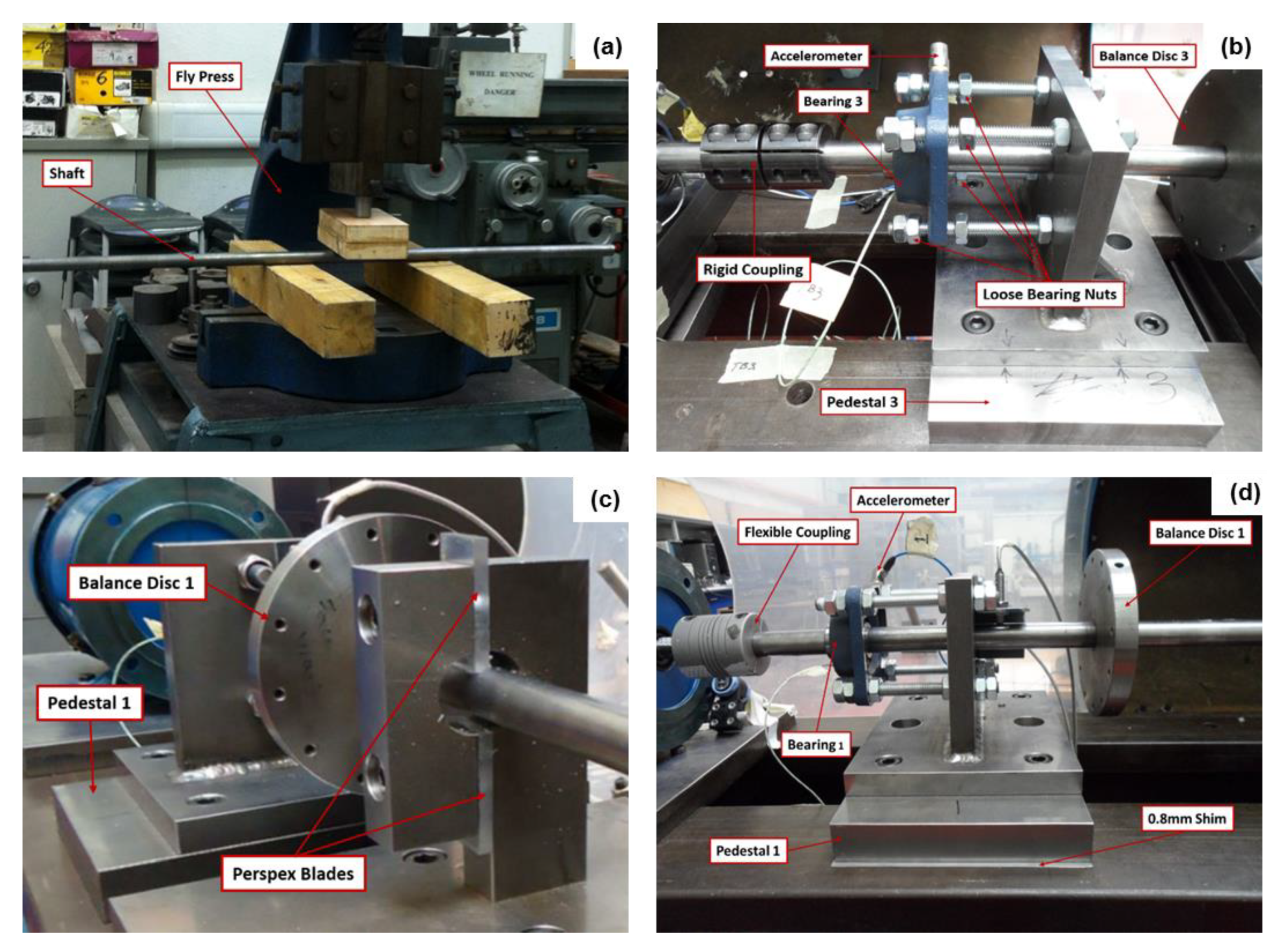
A total of five (i.e., baseline relatively healthy and four faults cases as shown in Figure 3) commonly encountered rotor-related cases were experimentally simulated, so as to cover a reasonably wide range of practical operating conditions of typical industrial rotating machines. It was impossible to achieve a perfect alignment while setting up the baseline case, as often is the situation in real-life scenarios. A summarised description of the mode of experimental simulation for each case, the location of the fault on the rig assembly and the severities are provided in Table 1 for simplification. Considering that several modern-day industrial rotating machines operate at multiple speeds, vibration data were collected at 3 distinct speeds; 1200 rpm (20 Hz), 1800 rpm (30 Hz) and 2400 rpm (40 Hz) for each case. This approach provides the opportunity to extensively understand the dynamics of the studied class of machines under different operating conditions. Under each experimental scenario (i.e., under each case and each machine speed), vibration data were obtained at a sampling rate of 10 kHz over a timespan of approximately 120 seconds.

4. Data Arrangement and Signal Processing Parameters

In this study, vibration data were collected under a total of 15 experimental scenarios. A scenario here represents a specific machine condition (e.g., rotor misalignment) at a specific machine speed (e.g., 40 Hz). Prior to applying any of the tools within the proposed hybrid framework, it was crucial to ensure that the measured vibration data under individual scenarios exhibit comparable signal processing characteristics such as number of data points, frequency resolution, sampling frequency, etc.

4.1. Data Arrangement for CCS Data Fusion

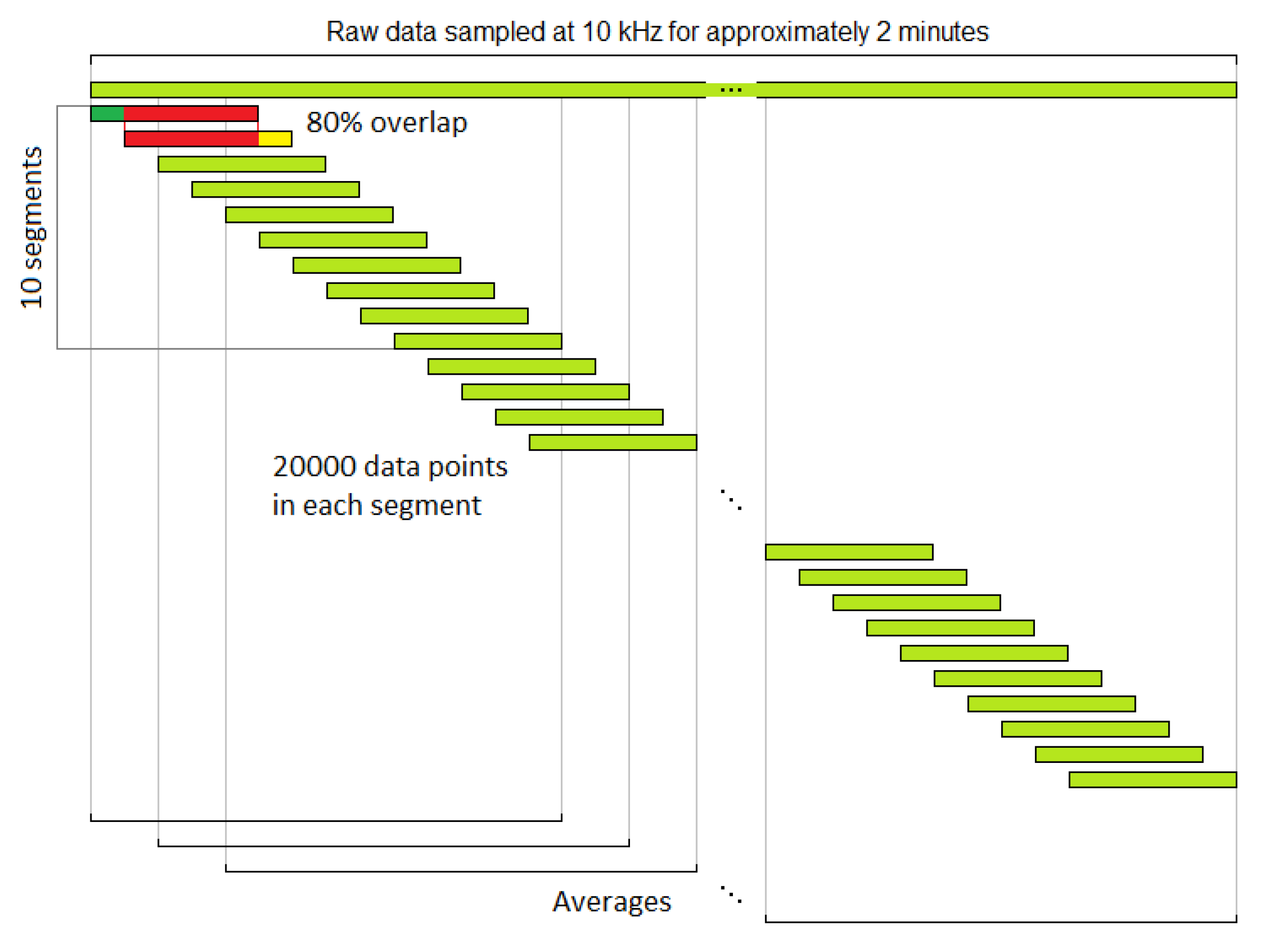
Data preparation for CCS commences with averaging. In the present work, an “average” refers to single complete CCS calculation, which is then converted into a sample with a number of features, for training, validating, or classification in the subsequent stage for machine learning classification. A two-stage overlap method was used for generating enough averages from the raw data (the higher the number of averages, the higher the similarities between the reconstructed and original signals). As shown in Figure 4, the initial stage of data preparation involves splitting the raw data into segments of 20,000 data points with an overlap of 80%. The next stage is to calculate the i th CCS average of the [ 2 ( i 1 ) + 1 ] to [ 2 ( i 1 ) + 10 ] th segments from each bearing pedestal using Hanning window. The sampling rate used is F S = 10 kHz and the frequency resolution is d f = 0.5 Hz. The number of raw data points, as well as the number of averages generated for each case is listed in Table 2.
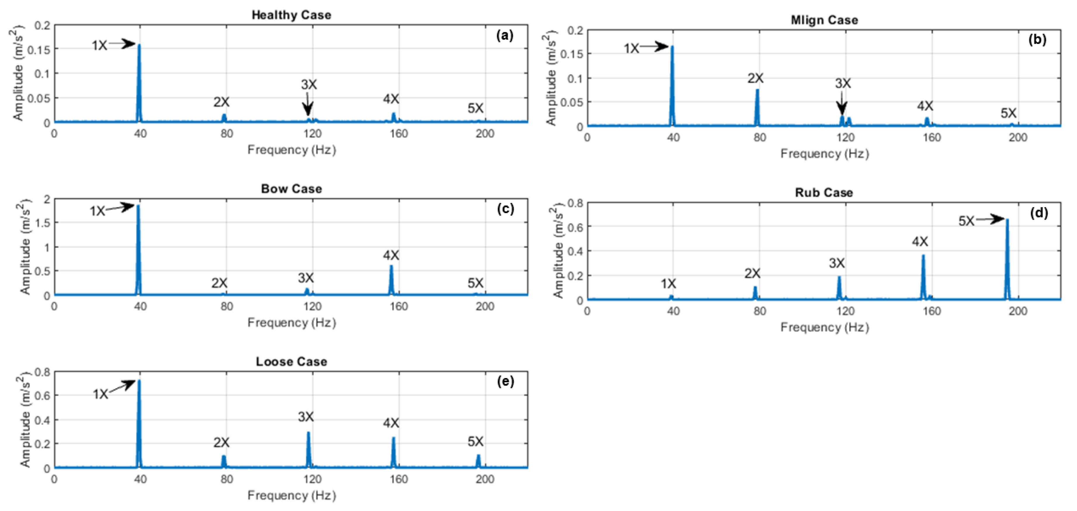
After the data preparation, Equations (1)–(7) were then use to generate the typical CCS shown in Figure 5. Each spectrum represents a specific case (i.e., Healthy, Bow, Loose, Mlign and Rub) at 2400 rpm (40 Hz). It is useful to reiterate that each CCS is a fusion of all vibration data from all 4 bearings, thereby providing a complete dynamics of the entire machine. During the faults diagnosis, only the first five harmonic components were considered, as it was adjudged that these would contain sufficient information to distinguish faults at these frequencies. Based on the types and magnitudes of the harmonics present alone, the Bow case exhibits much higher amplitudes at all harmonics than the other cases. In the Rub case however, the patterns of harmonics amplitudes can be described as the reverse of the Bow. The higher harmonics (especially 3X, 4X and 5X) had the highest amplitudes as opposed to Bow which had a far superior 1X amplitude. The Loose and Bow cases also displayed similar 1X and 4X harmonic patterns. Unlike in the other cases whereby harmonic patterns sometimes appeared similar but amplitudes may differ and vice versa, Healthy and Mlign cases were immensely similar and almost undistinguishable on all counts. This phenomenon was anticipated because of the low severity of misalignment in Mlign case coupled with the inherent residual misalignment in the Healthy case. In order to enhance the ability to distinguish faults at all speeds, SE feature was applied here based on Equation (8). The computed SEs for the harmonics were then used as inputs to the PCA stage.

4.2. Data Arrangement for Dimensionality Reduction

The SE of the CCS allows for the extraction of two features. Firstly the SE of 1X, 2X, 3X, 4X and 5X; and secondly the normalised harmonics is basically their ratios (e.g., 2X/1X, 3X/1X, 4X/1X and 5X/1X). By centralising and standardising each of these features according to Equations (9)–(12), 4 input data types (i.e., centralised SE, centralised ratio, standardised SE and standardised ratio), were generated for the PCA. The PCA converts these original features into the same number of principal components (PCs). The percentage of explained variance of each component indicates how much information the resultant PC holds. Typically, the first few PCs hold the vast majority of information. Based on this premise, the remaining PCs can, therefore, be discarded to reduce dimensionality of the dataset without necessarily compromising diagnosis quality. Table 3 provides a list of the percentages of explained variance for each PC for the different features at all speeds. Additionally, it is apparent that the combination of PCs 1 and 2 account for more than ¾ of the explained variance for each feature at all speeds.
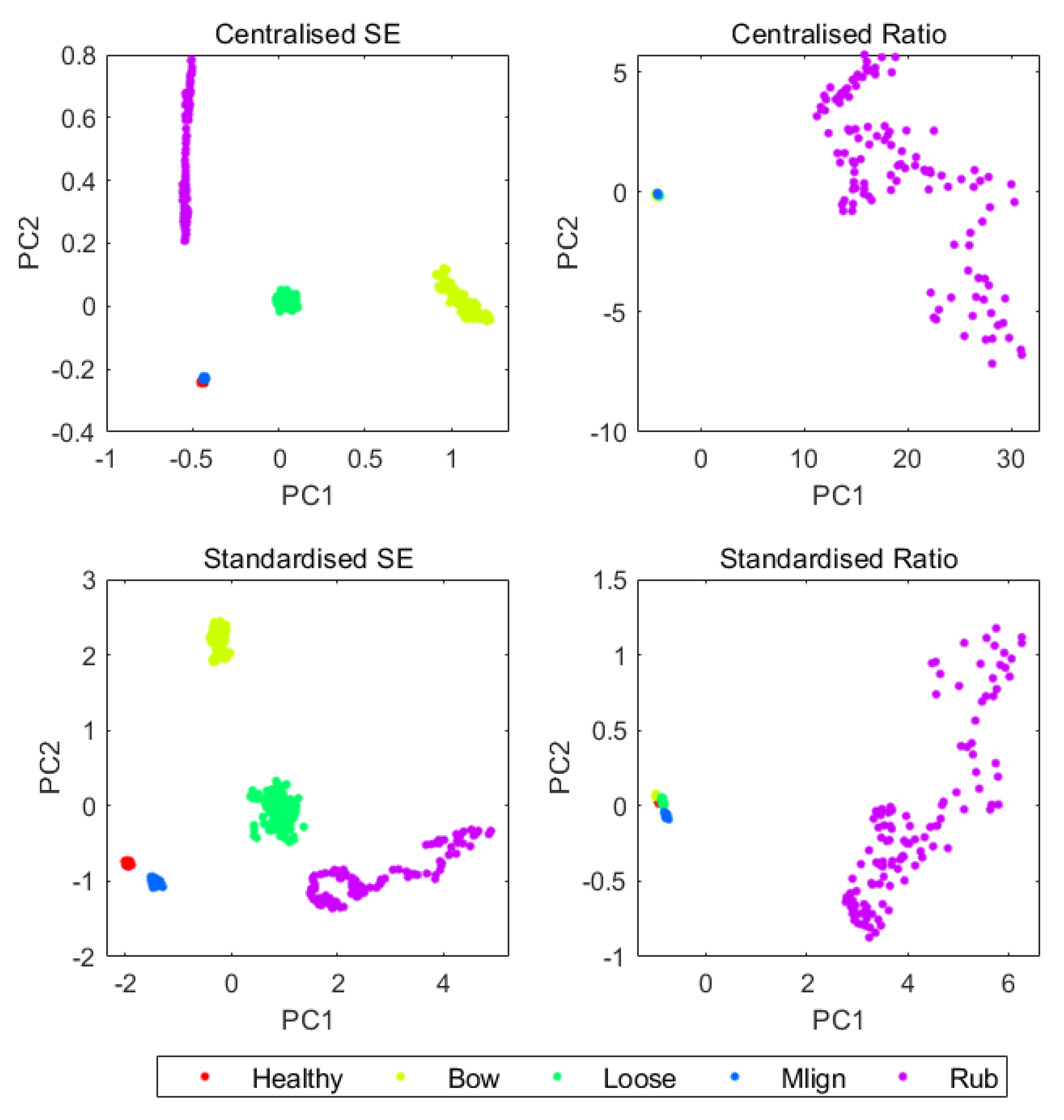
Figure 6 compares the PCA results of all four features at 40Hz so as to examine the stability of SE with PCA alone, so as to justify the need for more advanced machine learning approaches. Of all the speeds considered, only 40 Hz offered reasonable separation for all cases with SE as a feature. This was perhaps due to the enhanced amplitude of vibration at this speed due to its closeness to the first natural frequency. Despite the reasonably good performance of SE at 40 Hz, the use of PCA alone is limited because it is unable to effectively integrate all speeds into a single map. This is due to disparity in amplitude of vibration at different speeds. Hence multiple charts would be required for each speed.

5. Data Analysis and Discussion of Results

The results will be initially examined in the context of the classification accuracy of the various machine learning techniques with regards to all features at all machine speeds. This comparison would give an indication of the most optimised technique-feature combinations under different scenarios of speeds and case. The remainder of the results analysis entails the assessment of visualisation strength of the techniques.

5.1. Accuracy Comparison

As previously highlighted, earlier combinations of CCS and PCA for rotor-related faults classification yielded encouraging outcomes, all such efforts were wholly based on manual human observations of perceived patterns of new unlabelled samples. The dominance of human intervention was adjudged a potential weak link especially from the viewpoint of repeatability, which could eventually jeopardise the quality diagnosis when dealing with critical industrial rotating machines. Therefore, implementing an approach that is capable of learning historical patterns and then using such knowledge to perform future classifications would highly enhance reliability. By using PCs 1 and 2 with labels as input data for training and validating the machine learning classifiers as well as K-fold cross-validation method (i.e., K = 10), Table 4 displays a comparison of their accuracies for all features.
The results show that feature type has a significant effect on classification accuracy. The features which demonstrated the best performance at the PCA stage (i.e., centralised ratio at 20 Hz, standardised ratio at 30 Hz, and standardised SE at 40 Hz) also represent the best features for automatic fault classification for all the tested machine learning classifiers.

5.2. Visualised Decision Rules

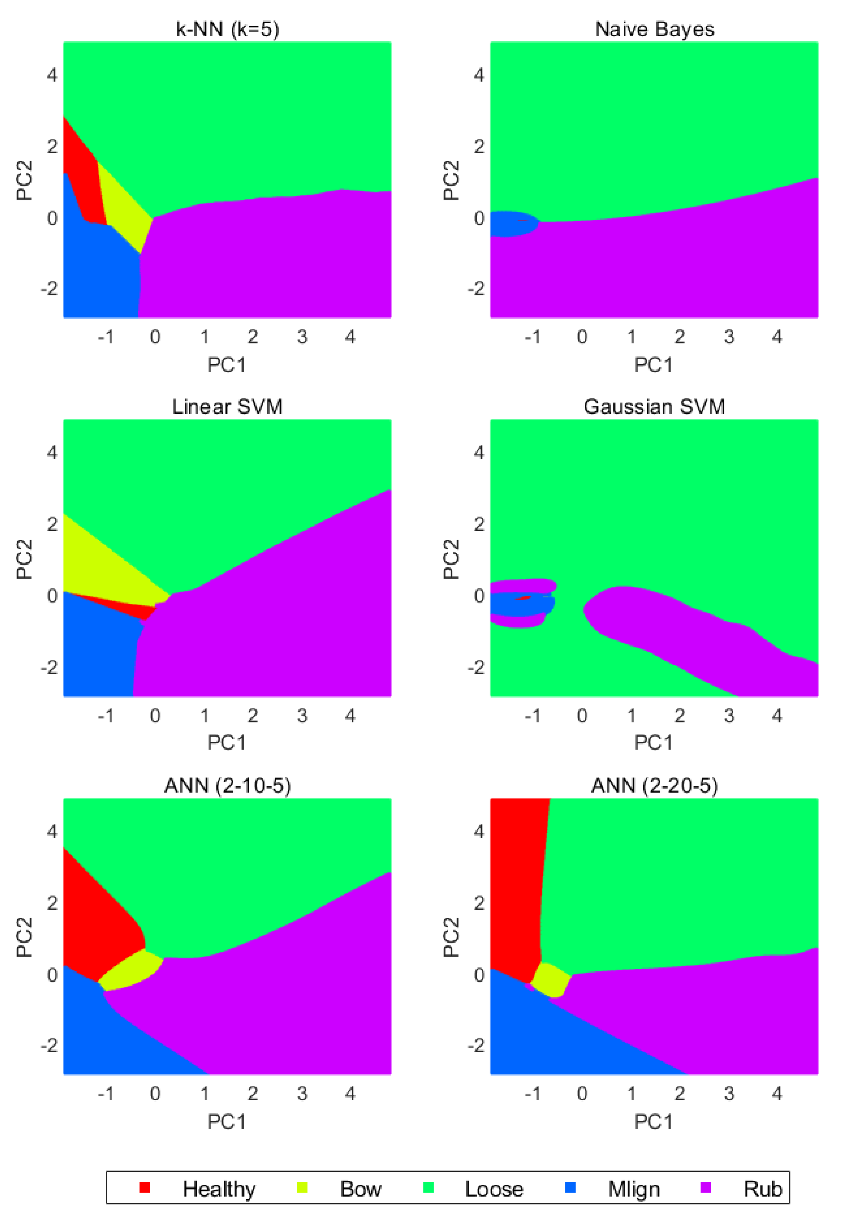
In order to further enhance understanding of the classification mechanisms, the 2D decision rules presented in Figure 7, Figure 8 and Figure 9 were developed. The trained classifiers divide the relevant regions of the PC1-PC2 plane into different sections. Each section of the region corresponds to individual faults. Furthermore, new unlabelled data points will then be assigned to sections that exhibit similar characteristics.
It is important to highlight that, under all three machine speeds examined, instances of severe over-fitting phenomena occurred for both Naïve Bayes and Gaussian SVM classifiers. The sections corresponding to Healthy and Mlign cases are quite minimal which could lead to incorrect classification of future data points. While a similar phenomenon was also evident for linear SVM under the Healthy case at 30 Hz, it demonstrated good outcomes at 20 Hz and 40 Hz speeds. K-NN and the two ANN classifiers displayed very good performance at all speeds. Judging by all-round performance, ANN offered the best results under all scenarios. The ANN architecture adopted here was based on a two-layered backward propagation (BP) network that applied sigmoid hidden and soft max output neurons. This architecture has the capability to classify vectors arbitrarily, provided adequate neurons exist within its hidden layer. The 2-10-5 and 2-20-5 configurations visible in Table 4 respectively represent the input number of neurons for the hidden layer output whereby the two inputs represent PC1 and PC2. The datasets was divided into 70 (for training), 15 (for validation) and 15 (for testing).

6. Conclusions and Future Work

Industrial rotating machines faults detection and classification using vibration-based approaches is widely applied across various industries over several decades. Despite the wealth of knowledge attributable to these classes of approaches, a significant amount of time is still attributable to their field-based implementation, which consequently impacts overall downtime and organisational profit margins. This is perhaps why recent research efforts have immensely focussed on the development of techniques that are capable of rationalising faults diagnosis data through data fusion. Such initiatives include the development of a composite spectrum (CCS) approach that uses a single spectrum to describe entire rotating machine dynamics, irrespective of the number of measurement locations. While initial findings from this approach yielded very encouraging outcomes, there still exist significant opportunities for improvement especially with regard to minimising or eliminating human intervention/subjectivity so as to enhance repeatability.
Building upon the earlier CCS multi-sensor data fusion technique, the current study presents an automatic hybrid approach that uses spectrum energy (SE) as its feature. The proficiency of the new SE feature with various machine learning classifiers with regards to different machine scenarios of speed and conditions is presented. This multi-features/multi-classifiers/multi-scenarios approach allows for adequate performance comparison. It was observed that classifiers, such as Naïve Bayes and Gaussian support vector machine (SVM), displayed instances of severe overfitting, owing to the minimal nature of the sections corresponding to Healthy and Mlign cases which could lead to incorrect classification of future data points. While this situation was also apparent for linear SVM under the Healthy case at 30 Hz, its performance at other speeds was quite good. While K-NN classifiers displayed reasonably good performance at all speeds, ANN offered an all-round best set of results under all scenarios. The findings recorded in the current study demonstrate immense opportunity for automating data fusion-based faults classification of industrial rotating machines. While the current study only examined rotor-related faults, future studies are planned towards testing the presented approach on other classes of faults especially high frequency faults associated with bearings and gears.

Author Contributions

Conceptualization, Validation, Data curation: A.Y.-K. and R.C.; Methodology, Resources, Writing—review and editing, Visualization, Supervision: A.Y.-K.; Software, Formal analysis, Investigation, Writing—original draft preparation: R.C. All authors have read and agreed to the published version of the manuscript.

Funding

This research received no external funding.

Conflicts of Interest

The authors declare no conflict of interest.

References

  1. Yunusa-Kaltungo, A.; Sinha, J. Condition Monitoring: A Simple and Practical Approach; LAP Lambert Academic Publishing: Saarbrücken, Germany, 2012. [Google Scholar]
  2. Kostek, R.; Landowski, B.; Muślewski, Ł. Simulation of rolling bearing vibration in diagnostics. J. Vibroengin. 2015, 17, 4268–4278. [Google Scholar]
  3. Saidi, L.; Ali, J.B.; Fnaiech, F. Application of higher order spectral features and support vector machines for bearing faults classification. ISA Trans. 2015, 54, 193–206. [Google Scholar] [CrossRef] [PubMed]
  4. Liang, B.; Iwnicki, S.D.; Zhao, Y. Application of power spectrum, cepstrum, higher order spectrum and neural network analyses for induction motor fault diagnosis. Mech. Syst. Signal Process. 2013, 39, 342–360. [Google Scholar] [CrossRef]
  5. Yunusa-Kaltungo, A.; Sinha, J.K.; Nembhard, A.D. Use of composite higher order spectra for faults diagnosis of rotating machines with different foundation flexibilities. Measurement 2015, 70, 47–61. [Google Scholar] [CrossRef]
  6. Yunusa-Kaltungo, A.; Sinha, J.K. Faults diagnosis in rotating machines using higher order spectra. In Proceedings of the ASME Turbo Expo 2014: Turbine Technical Conference and Exposition, Düsseldorf, Germany, 16–20 June 2014; American Society of Mechanical Engineers Digital Collection; ASME: New York, NY, USA, 2014. [Google Scholar]
  7. Arthur, N.; Penman, J. Induction machine condition monitoring with higher order spectra. IEEE Trans. Ind. Electron. 2000, 47, 1031–1041. [Google Scholar] [CrossRef]
  8. Chow, T.W.; Tan, H.Z. HOS-based nonparametric and parametric methodologies for machine fault detection. IEEE Trans. Ind. Electron. 2000, 47, 1051–1059. [Google Scholar] [CrossRef]
  9. McCormick, A.C.; Nandi, A.K. Bispectral and trispectral features for machine condition diagnosis. IEEE Proc. Vis. Image Signal Process. 1999, 146, 229–234. [Google Scholar] [CrossRef]
  10. Yang, D.M.; Stronach, A.F.; MacConnell, P.; Penman, J. Third-order spectral techniques for the diagnosis of motor bearing condition using artificial neural networks. Mech. Syst. Signal Process. 2002, 16, 391–411. [Google Scholar] [CrossRef]
  11. Yunusa-Kaltungo, A.; Sinha, J.K. Combined bispectrum and trispectrum for faults diagnosis in rotating machines. Proc. Inst. Mech. Eng. Part O J. Risk Reliab. 2014, 228, 419–428. [Google Scholar]
  12. Luo, S.; Cheng, J.; Zeng, M.; Yang, Y. An intelligent fault diagnosis model for rotating machinery based on multi-scale higher order singular spectrum analysis and GA-VPMCD. Measurement 2016, 87, 38–50. [Google Scholar] [CrossRef]
  13. Saidi, L.; Henao, H.; Fnaiech, F.; Capolino, G.A.; Cirrincione, G. Application of higher order spectral analysis for rotor broken bar detection in induction machines. In Proceedings of the 8th IEEE Symposium on Diagnostics for Electrical Machines, Power Electronics & Drives, Bologna, Italy, 5–8 September 2011; pp. 31–38. [Google Scholar]
  14. Yunusa-Kaltungo, A.; Sinha, J.K.; Elbhbah, K. HOS analysis of measured vibration data on rotating machines with different simulated faults. In Proceedings of the Advances in Condition Monitoring of Machinery in Non-Stationary Operations, Lyon, France, 15–17 December 2014; Springer: Berlin/Heidelberg, Germany, 2016; pp. 81–89. [Google Scholar]
  15. Saidi, L.; Ali, J.B.; Fnaiech, F. Bi-spectrum based-EMD applied to the non-stationary vibration signals for bearing faults diagnosis. ISA Trans. 2014, 53, 1650–1660. [Google Scholar] [CrossRef] [PubMed]
  16. Yunusa-Kaltungo, A.; Sinha, J.K. Generic vibration-based faults identification approach for identical rotating machines installed on different foundations, VIRM 11-Vibrations in Rotating. Machinery 2016, 11, 499–510. [Google Scholar]
  17. de la Rosa, J.J.; Muñoz, A.M. Higher-order cumulants and spectral kurtosis for early detection of subterranean termites. Mech. Syst. Signal Process. 2008, 22, 279–294. [Google Scholar] [CrossRef]
  18. Saidi, L.; Fnaiech, F. Bearing defects decision making using higher order spectra features and support vector machines. In Proceedings of the IEEE 14th International Conference on Sciences and Techniques of Automatic Control & Computer Engineering-STA’2013, Sousse, Tunisia, 20–22 December 2013; pp. 419–424. [Google Scholar]
  19. McCormick, A.C. Cyclostationary and Higher-order Statistical Signal Processing Algorithms for Machine Condition Monitoring. Ph.D. Thesis, University of Strathclyde, Glasgow, UK, 1998. [Google Scholar]
  20. Howard, I.M. Higher-order spectral techniques for machine vibration condition monitoring. Proc. Inst. Mech. Eng. Part G J. Aerosp. Eng. 1997, 211, 211–219. [Google Scholar] [CrossRef]
  21. Collis, W.B.; White, P.R.; Hammond, J.K. Higher-order spectra: The bispectrum and trispectrum. Mech. Syst. Signal Pr. 1998, 12, 375–394. [Google Scholar] [CrossRef]
  22. Rivola, A.; White, P.R. Use of higher order spectra in condition monitoring: Simulation and experiments. In Proceedings of the 1999 ASME Design Engineering Technical Conferences, Las Vegas, NV, USA, 12–15 September 1999; Paper No. DETC99/VIB-8332; ASME: New York, NY, USA, 1999. [Google Scholar]
  23. Yunusa-Kaltungo, A.; Sinha, J.K. A comparison of signal processing tools: Higher order spectra versus higher order coherences. J. Vib. Eng. Technol. 2015, 3, 461–472. [Google Scholar]
  24. Elbhbah, K.; Sinha, J.K. Vibration-based condition monitoring of rotating machines using a machine composite spectrum. J. Sound Vib. 2013, 332, 2831–2845. [Google Scholar] [CrossRef]
  25. Sinha, J.K.; Elbhbah, K. A future possibility of vibration based condition monitoring of rotating machines. Mech. Syst. Signal Process. 2013, 34, 231–240. [Google Scholar] [CrossRef]
  26. Yunusa-Kaltungo, A.; Sinha, J.K.; Elbhbah, K. An improved data fusion technique for faults diagnosis in rotating machines. Measurement 2014, 58, 27–32. [Google Scholar] [CrossRef]
  27. Yunusa-Kaltungo, A.; Sinha, J.K.; Nembhard, A.D. A novel fault diagnosis technique for enhancing maintenance and reliability of rotating machines. Struct. Health Monit. 2015, 14, 604–621. [Google Scholar] [CrossRef] [Green Version]
  28. Nembhard, A.D.; Sinha, J.K. Unified Multi-speed analysis (UMA) for the condition monitoring of aero-engines. Mech. Syst. Signal Process. 2015, 64, 84–99. [Google Scholar] [CrossRef]
  29. Jolliffe, I. Principal Component Analysis; Springer: Berlin/Heidelberg, Germany, 2011. [Google Scholar]
  30. Nagbe, K.; Cugliari, J.; Jacques, J. Short-Term Electricity Demand Forecasting Using a Functional State Space Model. Energies 2018, 11, 1120. [Google Scholar] [CrossRef] [Green Version]
  31. Shen, Y.; Abubakar, M.; Liu, H.; Hussain, F. Power Quality Disturbance Monitoring and Classification Based on Improved PCA and Convolution Neural Network for Wind-Grid Distribution Systems. Energies 2019, 12, 1280. [Google Scholar] [CrossRef] [Green Version]
  32. Papaioannou, G.P.; Dikaiakos, C.; Dramountanis, A.; Papaioannou, P.G. Analysis and Modeling for Short- to Medium-Term Load Forecasting Using a Hybrid Manifold Learning Principal Component Model and Comparison with Classical Statistical Models (SARIMAX, Exponential Smoothing) and Artificial Intelligence Models (ANN, SVM): The Case of Greek Electricity Market. Energies 2016, 9, 635. [Google Scholar]
  33. AbuBaker, M. Data Mining Applications in Understanding Electricity Consumers’ Behavior: A Case Study of Tulkarm District, Palestine. Energies 2019, 12, 4287. [Google Scholar] [CrossRef] [Green Version]
  34. Fei, W.; Moses, P. Fault Current Tracing and Identification via Machine Learning Considering Distributed Energy Resources in Distribution Networks. Energies 2019, 12, 4333. [Google Scholar] [CrossRef] [Green Version]
  35. Zeng, B.; Guo, J.; Zhu, W.; Xiao, Z.; Yuan, F.; Huang, S. A Transformer Fault Diagnosis Model Based On Hybrid Grey Wolf Optimizer and LS-SVM. Energies 2019, 12, 4170. [Google Scholar] [CrossRef] [Green Version]
  36. Feng, S.; Chen, J.; Tang, Y. Identification of Low Frequency Oscillations Based on Multidimensional Features and ReliefF-mRMR. Energies 2019, 12, 2762. [Google Scholar] [CrossRef] [Green Version]
  37. Xiao, C.; Liu, Z.; Zhang, T.; Zhang, L. On Fault Prediction for Wind Turbine Pitch System Using Radar Chart and Support Vector Machine Approach. Energies 2019, 12, 2693. [Google Scholar] [CrossRef] [Green Version]
  38. Liu, R.; Yang, B.; Zio, E.; Chen, X. Artificial intelligence for fault diagnosis of rotating machinery: A review. Mech. Syst. Signal Process. 2018, 108, 33–47. [Google Scholar] [CrossRef]
  39. Pająk, M.; Muślewski, Ł.; Landowski, B.; Grządziela, A. Fuzzy identification of the reliability state of the mine detecting ship propulsion system. Pol. Marit. Res. 2019, 26, 55–64. [Google Scholar] [CrossRef] [Green Version]
  40. Russell, S.J.; Norvig, P. Artificial Intelligence: A Modern Approach; Pearson Education Limited: Kuala Lumpur, Malaysia, 2016. [Google Scholar]
  41. Yunusa-Kaltungo, A.; Kermani, M.M.; Labib, A. Investigation of critical failures using root cause analysis methods: Case study of ASH cement PLC. Eng. Fail. Anal. 2017, 73, 25–45. [Google Scholar] [CrossRef]
  42. Reynolds, P.; Pavic, A. Quality assurance procedures for the modal testing of building floor structures. Exp. Tech. 2000, 24, 36–41. [Google Scholar] [CrossRef]
  43. Ewins, D.J. Basics and state-of-the-art of modal testing. Sadhana 2000, 25, 207–220. [Google Scholar] [CrossRef] [Green Version]
  44. Ewins, D.J. Modal Testing: Theory, Practice and Application, 2nd ed.; Research Studies Press: Hertfordshire, UK, 2000. [Google Scholar]
  45. Wang, J.; Xu, M.; Zhang, C.; Huang, B.; Gu, F. Online Bearing Clearance Monitoring Based on an Accurate Vibration Analysis. Energies 2020, 13, 389. [Google Scholar] [CrossRef] [Green Version]
  46. Aggarwal, A.; Strangas, E.G. Review of Detection Methods of Static Eccentricity for Interior Permanent Magnet Synchronous Machine. Energies 2019, 12, 4105. [Google Scholar] [CrossRef] [Green Version]
  47. Li, X.; Elasha, F.; Shanbr, S.; Mba, D. Remaining Useful Life Prediction of Rolling Element Bearings Using Supervised Machine Learning. Energies 2019, 12, 2705. [Google Scholar] [CrossRef] [Green Version]
  48. Salomon, C.P.; Ferreira, C.; Sant’Ana, W.C.; Lambert-Torres, G.; Borges da Silva, L.E.; Bonaldi, E.L.; de Oliveira, L.E.L.; Torres, B.S. A Study of Fault Diagnosis Based on Electrical Signature Analysis for Synchronous Generators Predictive Maintenance in Bulk Electric Systems. Energies 2019, 12, 1506. [Google Scholar] [CrossRef] [Green Version]
  49. Shi, R.; Zhang, X. VSG-Based Dynamic Frequency Support Control for Autonomous PV–Diesel Microgrids. Energies 2018, 11, 1814. [Google Scholar] [CrossRef] [Green Version]
  50. Caruso, M.; Di Tommaso, A.O.; Marignetti, F.; Miceli, R.; Ricco Galluzzo, G. A General Mathematical Formulation for Winding Layout Arrangement of Electrical Machines. Energies 2018, 11, 446. [Google Scholar] [CrossRef] [Green Version]
Figure 1. Proposed automated fault classification approach flow chart.
Energies 13 01394 g001
Figure 2. Experimental rig.
Energies 13 01394 g002
Figure 3. Faults simulation (a) rotor bow (b) bearing looseness (c) rotor rub (d) rotor misalignment.
Energies 13 01394 g003
Figure 4. Two-stage overlap method for the preparation of datasets.
Energies 13 01394 g004
Figure 5. Typical CCS for all cases at 40Hz. (a) Healthy; (b) Mlign; (c) Bow; (d) Rub; (e) Loose.
Energies 13 01394 g005
Figure 6. PCA results for four feature extraction methods at 40 Hz.
Energies 13 01394 g006
Figure 7. Visualised decision rules for the centralised ratio at 20 Hz.
Energies 13 01394 g007
Figure 8. Visualised decision rules for the standardised ratio at 30 Hz.
Energies 13 01394 g008
Figure 9. Visualised decision rules for the standardised SE at 40 Hz.
Energies 13 01394 g009
Table 1. Description of experimentally simulated cases.
CaseDescriptionAbbreviationSeverity and Location
1Healthy with residual misalignmentHealthyThe reference case likely contains some residual misalignment at the couplings, due to manufacturing and assembly imperfections
2Rotor bowBow3.4 mm run-out was created at the centre of the 1000 mm shaft.
3Rotor misalignmentMlign0.8 mm mild steel shim beneath RHS of bearing 1 foundation
4Bearing loosenessLooseLoosening some of the bearing 3 threaded bar nuts
5Rotor rubRubPartial rub using two Perspex blades (TDC and BDC of 1000 mm shaft), 275 mm from bearing 1
Table 2. The number of raw data points and averages in each case.
Speed20Hz30Hz40Hz
Case CodeRaw DataAveragesRaw DataAveragesRaw DataAverages
Healthy1,272,0001531,279,0001531,110,000132
Bow1,266,0001521,271,0001521,266,000152
Loose1,058,0001261,248,0001501,261,000151
Mlign996,000118927,000109928,000110
Rub1,259,0001511,271,000152994,000118
Total-700-716-663
Table 3. Percentage of explained variance by each PC.
SpeedFeature ExtractedPC1PC2PC3PC4PC5PC 1&2
20 HzCentralised SE98.80460.93270.19150.06970.001599.7373
Centralised ratio83.422811.35854.66200.5567N/A94.7813
Standardised SE47.357235.689013.23283.37190.349283.0462
Standardised ratio45.853626.793722.39154.9611N/A72.6473
30 HzCentralised SE80.267814.57104.83460.31960.006994.8389
Centralised ratio86.417210.93022.34090.3117N/A97.3474
Standardised SE50.290232.792014.75932.13180.026783.0822
Standardised ratio57.785424.819215.98711.4083N/A82.6047
40 HzCentralised SE85.349413.20580.77430.60890.061698.5552
Centralised ratio97.35502.36940.24330.0323N/A99.7244
Standardised SE55.118931.600410.72111.85110.708586.7193
Standardised ratio97.59271.58370.65590.1677N/A99.1764
Table 4. Accuracy of different machine learning classifiers (%).
SpeedFeature Extractedk-NN k = 5Naïve BayesLinear SVMGaussian SVMANN 2-10-5ANN 2-20-5
20HzCentralised SE98.1498.2998.498.197.797.9
Centralised Ratio98.7198.5798.999.399.099.3
Standardised SE93.4385.4394.094.493.394.0
Standardised Ratio88.5784.7188.088.789.790.1
30HzCentralised SE94.1394.4196.194.794.195.9
Centralised Ratio96.7996.5197.998.683.583.9
Standardised SE99.1698.4698.999.498.398.6
Standardised Ratio100100100100100100
40HzCentralised SE98.1997.8998.098.596.898.0
Centralised Ratio10095.1799.499.787.998.0
Standardised SE100100100100100100
Standardised Ratio10010010010099.896.2