Abstract
The article presents an assessment of the potential for using low enthalpy geothermal resources for electricity generation on the basis of the Małopolskie Voivodeship (southern Poland). Identification the locations providing the best prospects with the highest efficiency and possible gross power output. Thermodynamic calculations of power plants were based on data from several geothermal wells: the Bańska PGP-1, Bańska IG-1, Bańska PGP-3 and Chochołów PIG-1 which are working wells located in one of the best geothermal reservoirs in Poland. As the temperature of geothermal waters from the wells does not exceed 86 °C, considerations include the use of binary technologies—the Organic Rankine Cycle (ORC) and Kalina Cycle. The potential gross capacity calculated for existing geothermal wells will not exceed 900 kW for ORC and 1.6 MW for Kalina Cycle. In the case of gross electricity, the total production will not exceed 3.3 GWh/year using the ORC, and will not exceed 6.3 GWh/year for the Kalina Cycle.
1. Introduction
The development of the energy sector, including electricity generation, increasingly takes into account the use of renewable energy sources (RES). This is particularly evident in the countries of the European Union (EU), which are obliged to reduce emissions of pollutants into the atmosphere, increase energy efficiency and increase the share of renewable energy in the structure of total gross energy generation [1]. However, this does not only apply to European Union countries, because it should be noted globally that in 2018 the share of renewable energy sources in total electricity generation was 26%, in heating and cooling it was 10%, while in transport 3.3% [2]. There is a change of direction in the energy market, in which RES plays an increasingly important role. This arises not only from concern for the environment, but is also an attempt to diversify energy sources in developing countries. This is particularly important in the case of electricity generation, since there is an increase in the consumption of electricity. In 2018, 181 GW of renewable energy capacity was installed worldwide for the purposes of electricity generation, and the total installed capacity reached the level of 2378 GW [2].
Analyzing data for individual renewable energy technologies, it should be noted that, by far at the end of 2018, hydropower was characterized by the largest installed capacity in the world—1132 GW. Wind energy with 591 GW came second, followed by 505 GW from photovoltaic, bio-energy with 130 GW, geothermal energy with 13.3 GW, concentrating solar thermal technologies (CSR) with 5.5 GW, and ocean energy with 0.5 GW [2]. Among the available renewable energy technologies, stable and continuous electricity generation can be provided by hydropower, biomass/biogas, and geothermal energy [3]. Solar power (photovoltaics) and wind energy, despite the fact that they are the most dynamically developing technologies [4], are heavily dependent on atmospheric conditions, and energy generation is often difficult to predict. Hence the need for RES development towards more stable sources. In view of the above, the generation of electricity using geothermal energy is of particular importance. This is undoubtedly a source of energy that fits in with the strategy of a low-carbon energy mix becoming the basis of a modern economy [5,6].
The temperature and hydrogeological conditions determine the technology of electricity generation using geothermal energy. Due to the type of energy carrier and its temperature, several basic ways are highlighted for converting the heat energy accumulated in geothermal vapor or waters, as well as in hot dry rocks, into electricity. These are dry steam power plants (180–300 °C), single-flash or double-flash steam power plants (150–320 °C), Organic Rankine Cycle and Kalina Cycle (90–150 °C) [7]. Most of the geothermal power plants in the world use energy accumulated in wet or less dry geothermal fluids [8]. From the point of view of the geothermal conditions in Poland (temperatures up to 100 °C), it is necessary to consider Organic Rankine Cycle (ORC) and Kalina Cycle technologies. A classification of geothermal resources in Poland by temperature, enthalpy and exergy was presented by Barbacki (2012) [9]. In both cases, the thermodynamic cycle is based on the use of an additional working fluid (Figure 1) [10]. Geothermal water is extracted by the production well, which transfers heat to the evaporator with a working fluid that has a significantly lower boiling point temperature. The energy released by the evaporator causes the working fluid to evaporate. In the case of ORC installations, many types of organic working fluids are used i.e. R600a, R236a and R227ea. In systems based on the Kalina Cycle, an inorganic working fluid, a mixture of ammonia and water, is used [10,11]. The Kalina Cycle uses a change in the solubility of ammonia in water, which is related to the varying temperature of the ammonia/water mixture. The potential energy accumulated in the working medium vapor (associated with the high pressure of the working medium vapor) is used by a turbine connected to the generator. The working fluid is returned to the evaporator for reuse. In many cases, geothermal water is injected into the rock or used for other purposes such as heat generation, recreation etc.
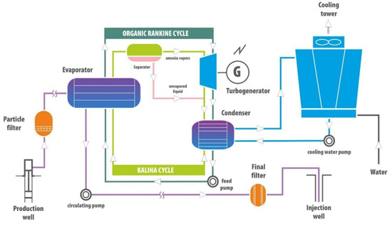
Figure 1.
Simplified comparison of the Organic Rankine Cycle (ORC) and the Kalina Cycle (based on [7,12]).
For the thermodynamic calculations, it was necessary to recognize thermal and hydrogeological parameters in the research area. Małopolska Voivodship located in southern Poland was selected, which resulted from a very interesting and diversified geological structure of the region, as well as the fact that the first geothermal heating plant in Poland—PEC Geotermia Podhalańska S.A. operates in this area.
No geothermal power plant has been commissioned in Poland. However many studies have been carried out to determine the potential of electricity generation using geothermal energy which has resulted in the “Atlas of the possible use of geothermal waters for combined production of electricity and heat using binary systems in Poland” in 2014 [13]. This study presents the locations of the 10 best prospects for electricity generation. The evaluation was done in a comprehensive manner, taking into consideration the issue of heat generation which is an indispensable process accompanying the operation of the ORC power plant, and taking into account economic and ecological factors. The results obtained, considered in the context of the amount of electricity generated in the ORC system, indicate that the area with the best prospects is the Podhale region in the Małopolska voivodeship. Studies on a laboratory installation, which will allow one to generate electricity using Polish geothermal resources, have been described in Nowak et al. (2010) [14]. This generates electricity using heat from the district heating network. Electricity production by direct geothermal steam utilization is not relevant for Poland because of accessible geothermal conditions [15].
The global experience resulting from the operation of a geothermal power plant based on the ORC and the Kalina Cycle indicates that electricity generation always takes place in combination with heat generation. The exception is one installation in Chena Hot Springs (Alaska), due to the low temperature of the geothermal source (74 °C). Taking into account the Polish conditions connected with the use of geothermal energy and high demand for heat, the calculation was made on the assumption that both electricity and heat will be generated.
Key parameters influencing electricity generation are geothermal water temperature and flow rate. Rock mass temperature is determined by the density of the Earth’s thermal flux, thermal conductivity and specific heat of the rocks. The performance of potential geothermal exploration depends on many lithostratigraphic factors and rock tectonics, however, it can be estimated on the basis of the drilling data analysis.
Based on a literature analysis [10,12,13,15,16,17,18,19,20] and considering the parameters of geothermal power plants in the world, the minimum water temperature was assumed to be 74 °C and the geothermal flow rate to be 100 m3/h. The temperature standard is based on the operating parameters of the ORC plant in Chena Hot Spring (Alaska), the geothermal power plant with the lowest water temperature in the world. However, it should be added that the installation is also characterized by the low condensing temperature [7,19,21]. In the case of a geothermal water flow rate, the assumed value of 100 m3/h is also dictated by the approximate geothermal capacity of Chena Hot Spring in Alaska (115 m3/h) and in Neustadt-Glewe (110 m3/h) in Germany [21,22,23].
2. Materials and Methods
Data for 184 drilling wells located in the study area were used to identify geological and hydrogeological conditions. Due to the aim of this work, the geological information obtained from drilling depths exceeding 2000 m b.g.s. (meters below ground surface) was crucial. In order to assess the variability of rock mass thermal parameters in the Małopolska, borehole data and additional literature were used [24,25,26,27,28,29] to prepared maps for the distribution of geothermal gradient and temperatures at depths of 0.5, 1000, 2000, 3000, 4000 m b.g.s.
Both the geothermal gradient distribution map and depth temperature distribution maps were made used point data in two- and three-dimensional system and their exposure in the assumed coordinate system. This is possible thanks to the use of mathematical formulas and the interpolation and extrapolation of values in an area not covered by data.
The method of kriging was used, which is considered to give the best results for isoline maps created by interpolation [30]. A linear variogram model was used, which is the basic interpolation giving the effect of a regular value grid. The interpolation grid geometry parameters were determined automatically, based on the range of input data variability.
Albers Equal Area cartographic projection based on Krassovsky ellipsoid (1940), at the Central Meridian 190, was used to present the thermal parameter. The methodology was developed at the Department of Fossil Fuels of the AGH University of Science and Technology in Cracow [25].
Geothermal gradient map was prepared on the basis of temperature interpretation in individual holes, based on the formula [26]:
where:
- GT—geothermal gradient [°C/100 m]
- Ts—temperature at the top geothermal aquifer [°C]
- Tp—average annual surface temperature (mainly 0.5 m above sea level) [°C]
- Z—the depth of retaining the ceiling of the tested hydro-geothermal level [m b.g.s.]
In order to use formula (1), it was necessary to determine the average temperature at a depth of 0.5 m above sea level For this purpose, data published by Górecki [ed.] (2006) [25], Górecki [ed.] (2011) [28] and Górecki [ed.] (2012) [29] were used. The data obtained as a result of calculations were used to elaborate a geothermal gradient distribution map.
The data used to prepare the depth temperature maps were primarily the thermal profiles of the geothermal wells: Bańska PGP-1, Bańska IG-1, Głogoczów IG-1, Potrójna IG-1, Siekierczyna IG-1 and Zawada 8K. Lack of sufficient thermal data in the studied area, especially in its northern and western parts, caused that as supplementary data were used values from the geothermal gradient distribution map and depth distribution maps presented in the works of Górecki [ed.] (2006) [25], Górecki [ed.] (2011) [28] and Górecki [ed.] (2012) [29]. Temperature maps at the designated depths were made based on the results of calculations according to the formula [26]:
where:
- Ts—temperature at the top geothermal aquifer [°C]
- Tp—average annual surface temperature (mainly 0.5 m above sea level) [°C]
- GT—geothermal gradient of the tested level [°C/100 m]
- Zp—ordinate of the land surface [m a.s.l.]
- Zs—ordinate of the top geothermal aquifer [m a.s.l.]
In the thermodynamic calculations, it was assumed that the temperature of the geothermal water leaving the geothermal power plant would be at least 60 °C. The working fluid condensation temperature was adopted as a constant value of 30 °C. The amount of gross geothermal electricity produced was calculated from the gross power and working time. It was assumed that the power plant’s working time would be about 4000 h.
In the case of Organic Rankine Cycle, for detailed calculations, four dry working fluids were selected: R227ea, R600a, R236fa, R245fa and two wet: R1234yf and R134a. For the calculations, a thermodynamic model was developed with values of temperature, pressure, enthalpy and entropy at specific points determined using NIST REFPROP 9.1. It was assumed that a power plant based on the Organic Rankine Cycle consisted of a turbine, a condenser, a feed pump, a preheater, an evaporator and a superheater (Figure 2). The gross power can be described in accordance with the first principle of thermodynamics [10,17,31,32]:
where:
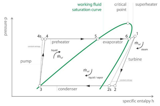
Figure 2.
Pressure enthalpy diagram with applied specific points; Explanation: 1–2s—isentropic expansion of the working fluid in the turbine; 2–2s—cooling of the working fluid in the condenser; 2s–3—condensation of the working fluid in the condenser; 3–4s—isentropic pumping of the working fluid by the feed pump; 5—heating of the working fluid in the preheater; 5–6—evaporating of the working fluid in the evaporator; 6–1—superheating of the working medium in the superheater (based on [10]).
- gross power [W]
- —heat flux supplied to the superheater, evaporator and preheater [W]
- —thermal efficiency [-]
- —mass flow of the working fluid [kg/s]
- hwf1, hwf4—specific enthalpy [kJ/kg]
The efficiency of the geothermal power plant was calculated based on the formula:
where:
- —thermal efficiency [-]
- hwf1, hwf2, hwf3, hwf4—specific enthalpy [kJ/kg]
The Organic Rankine Cycle, along with the characteristic points for which the enthalpy value is required, is shown in Figure 2.
For the calculation model, it was assumed that the Kalina Cycle consisted of a turbine (combined with a generator), a low-temperature recuperator, a condenser, a feed pump, a high-temperature recuperator, an evaporator and a separator (Figure 3). Calculations were made for mixtures in the proportion of 82% to 92% of ammonia content in relation to water. Each of the listed components should be considered separately when designing the system. The gross power was calculated based on the formula [10,17,31,32]:
where:
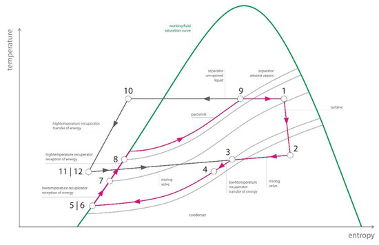
Figure 3.
Pressure entropy diagram with applied specific points; Explanation: 1–2—isentropic expansion of the working fluid in turbine, 2–3—mixing of ammonia vapors with the liquid part of the mixture; 3–4 and 6–7—heat transfer in low-temperature recuperator; 4–5—condensation of the working medium in the condenser; 5–6—isentropic pumping of the working medium through the feed pump; 7–8 and 10–11—heat transfer in the high-temperature recuperator; 8–9—evaporation of the working medium in the evaporator; 9–1—separation of ammonia vapors from the part of the mixture which has not evaporated; 11–12—expansion in the expansion valve (based on [33]).
- gross power [W]
- —heat flux supplied to the evaporator [W]
- —thermal efficiency [-]
- —mass flow of the working fluid [kg/s]
- hwf1, hwf8—specific enthalpy [kJ/kg]
The efficiency of the geothermal power plant was calculated based on the formula:
where:
- —thermal efficiency [-]
- hwf4, hwf5, hwf8, hwf9—specific enthalpy [kJ/kg]
The Kalina Cycle with the characteristic points for which the enthalpy value is required is shown in Figure 3.
During thermodynamic model studies, it was found that for the geothermal water temperature range analyzed the optimum percentage of ammonia in the mixture was 85% to 89%. To determine this range, a trial and error method of thermodynamic analysis was carried out using NIST REFPROP 9.1 for ammonia content in a mixture of 75% to 90%. Thus, the results of the three types of the mixture were presented: 85%, 87% and 89% ammonia content. The turbine pressure was selected in the range of 1500–3000 kPa for optimum results.
3. Characteristic of Research Area
Małopolskie Voivodeship is situated in the southern part of Poland, bordered by the Świętokrzyskie Voivodeship (north), Podkarpackie Voivodeship (east), Silesian Voivodeship (west) and the southern border with Slovakia (Figure 4). It occupies an area of 15,183 km2, which is 5% of Poland’s territory. This area is inhabited by approximately 3.3 million people and the level of urbanization is about 49.3%.
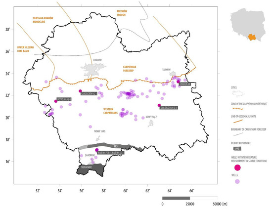
Figure 4.
Map of the main geological units of the Małopolskie Voivodeship (based on [24,34]).
Geologically, the Małopolskie Voivodeship comprises several structures, including the Upper Silesian Coal Basin, the Miechów Trough, the Silesian-Kraków Monocline, the Carpathian Foredeep and the Western Carpathians (Figure 4). The geological structure of the research area and its geothermal conditions have been well-recognized and described in the literature e.g., [25,28,29].
The terrain is high and mountainous. More than 50% of the area is above 500 m. Within the research area, 6 national parks, 11 landscape parks, 10 protected landscape areas and 84 nature reserves have been established. In terms of hydrology, the area of the Małopolskie Voivodeship is within the catchment of two river basins, the Vistula (90% of the area) and the Danube.
The Upper Silesian Coal Basin covers the western part of the Małopolskie Voivodeship, taking a small percentage of the whole voivodeship. It is characterized by an average geothermal gradient of 3.15 °C/100 m [35], with higher values of geothermal gradient and temperature recorded in the western part of the basin. The occurrence of geothermal waters was identified in Palaeozoic and Mesozoic formations: Triassic, Locally Jurassic, Carboniferous and Permian [36]. Due to the shallow Mesozoic deposits and unfavorable reservoir parameters of the Palaeozoic, geothermal parameters within the Upper Silesian Coal Basin are characterized by a temperature of 20 to 100 °C and a potential flow rate not exceeding 40 m3/h [24]. The deep coal mines of the Upper Silesian Coal Basin have a certain potential, but the temperature of geothermal waters does not exceed 45 °C [37]. From the perspective of electricity generation, this excludes the possibility of their use.
The Silesian–Kraków Monocline covers the north-western part of the Małopolska Voivodeship. Within it, geothermal waters were found in Palaeozoic and Mesozoic formations. However, the possibility of obtaining them is limited primarily by the poor recognition of the geothermal conditions of the Palaeozoic. In the case of younger Mesozoic layers (Triassic and on a smaller scale Jurassic) the temperature of geothermal waters does not exceed 20 °C [24,38,39].
The Miechów Trough is one of the structures of the Polish Lowlands, and is specifically the south-eastern part of the Szczecin–Łódzko-Miechów synclinorium. The average geothermal gradient values in the Miechów Trough range from 1.72 to 2.96 °C/100 m and the heat flux density is about 50 mW/m2 [35,40]. Within the Miechów Trough, the occurrence of geothermal waters has been observed in Palaeozoic and Mesozoic formations. The greatest hydrogeological potential in this area is represented by Devonian, Reich (Upper Triassic), Dogger (Central Jurassic) and Cenoman (Upper Chalk). The geothermal waters do not exceed 102 °C and the maximum flow rate is 20 m3/h [24]. Therefore, from the point of view of electricity generation, the Miechów Trough area is excluded from consideration due to the low flow rates of the production wells.
The Carpathian Foredeep is about 300 km long and is from a few (in the vicinity of Cracow) to 100 km (in the eastern part) wide, extending between the Carpathians to the south and the highlands of Central Poland to the north and occupying an area of about 20,000 km2 (6.5% of the area of Poland). Geothermal waters occurring in the area of the Carpathian Foredeep are primarily associated with Neogene (Miocene), Mesozoic (Cenoman, Dogger) and locally Palaeozoic (Carboniferous, Devonian) rocks. The thermal flux in the area of the Carpathian Foredeep is in the range of 60–95 mW /m2. The geothermal gradient is characterized by a large variability and ranges from 1.8 to over 4.5 °C/100m. The temperatures of geothermal waters are in the range of 20–90 °C, and the flow rate of geothermal waters is typically several cubic meters per hour. Water mineralization in the Carpathian Foredeep rises from east to west in the range of 1–150 g/L [24,41,42,43,44]. Despite locally relatively high temperatures of geothermal waters reaching up to 90 °C, the problem for their use for energy purposes however is the low flow rate not exceeding several cubic meters per hour.
The Western Carpathians are pushed north to the Miocene sediments of the Carpathian Foredeep. In Poland, the Western Carpathians represent the scarp of a mountain chain more than 1300 km long, running from Vienna to the Iron Gate on the Danube. The chain is divided into the Inner Carpathians (late Cretaceous folds) and younger Outer Carpathians (Flysch) and at the boundary between them is a band of pale rock.
The occurrence of geothermal waters has been reported in the Western Carpathians in Palaeozoic, Mesozoic and Neogene formations. The thermal flux in the Polish part of the Western Carpathians oscillates at the level of 60–95 mW/m2. The geothermal gradient is characterized by a number of variations, ranging from 2 to over 3.6 °C/100 m [28]. The temperatures of geothermal waters are in the range of 20–127 °C (temperatures above 80 °C occur in the area of the Podhale Basin), and the flow rate is from several cubic meters per hour to a maximum of 550 m3/h (Banská PGP-1) [45,46]. The mineralization of geothermal waters in the Polish part of the Western Carpathians ranges from about 0.5 to over 120 g/L, whereas in the best prospect from the point of view of the prevailing geothermal conditions, the area of the Podhale Basin, it is about 3 g/L [45,47,48].
The best prospect from the point of view of electricity generation is the area of the Podhale Basin. This area (a dozen kilometers wide), is a vast asymmetric depression at the foot of the Tatra Mountains, being part of the Central Carpathian Palaeogean Basin. This basin is composed of the Reglowa and Wierchowa nappes and a crystalline massif of the Tatra Mountains with sediment cover [45,49,50]. The aquifers of the Podhale Geothermal System are limestone and Triassic dolomites (with the most abundant geothermal waters in Małopolskie Voivodeship), sandstones and carbonate rocks (Jurassic) and eocene carbonates. The Tatra Mountains have the functions of a supply area and barrier to the south, while an impermeable northern boundary of the basin is the Pieniny Klippen Belt. The insulating cover is the Podhalansian Flysch [24,45]. The thermal flow in the area of the Podhale Geothermal System ranges from 55 to 60 mW/m2 and the geothermal gradient ranges from 1.9 to 2.3 °C/100 m. Geothermal waters at a depth of 2.0–3.2 km are characterized by a temperature of about 80–95 °C (geothermal water temperature rises with increasing depth northward from the supply zone, which is the Tatra), with a flow rate of 50–550 m3/h. The reservoir has an artesian character; the maximum static head pressure is up to 29 bar. The mineralization of geothermal waters in the area discussed amounts to approx. 3 g/dm3 [45].
4. Results
4.1. Geothermal Conditions in Research Area
Based on the results of the analysis, it should be stated that the highest values of the geothermal gradient (Figure 5) are found in the Silesian-Kraków Monocline—3.0 °C/100 m—and locally the eastern part of the Western Carpathians—also 3.0 °C/100 m. The lowest values of the geothermal gradient are observed in Podhale, around Nowy Targ and Zakopane—2.1 °C/100 m. The range of temperatures at depths of 1000 and 2000 m do not show sufficient value from the point of view of electricity generation. In the case of a temperature at a depth of 1000 the values do not exceed 40 °C and at a depth of 2000 m 70 °C. Temperatures at a depth of 3000 m b.g.s. range from 70 to 100 °C (Figure 6), reaching the highest values in the central part of the Carpathian Foredeep (near Cracow) and in the south-eastern part of the Western Carpathians (east of Nowy Sącz). The lowest temperatures above 70 °C can be observed in the central part of the Western Carpathians (near Nowy Targ) and in the Miechów Trough (north of Cracow). The most favorable temperature parameters were observed at a depth of 4000 m (Figure 7), which results directly from the rise of temperature with depth. The highest temperature values in the Małopolskie Voivodship are characterized by the area of the Upper Silesian Coal Basin and Silesian–Kraków monocline—with temperatures of 130–140 °C. High temperatures are also described in the south-eastern part of the Western Carpathians (east of Nowy Sącz)—from 120 to 130 °C. The lowest temperature values are observed in the eastern part of the Carpathian Foredeep (near Tarnów) and in the central part of the Western Carpathians (around Nowy Targ and Zakopane)—temperatures do not exceed 105 °C.
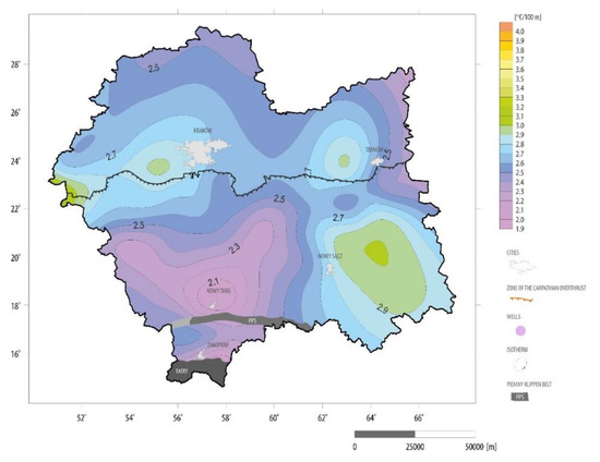
Figure 5.
Map of geothermal gradient in Małopolskie Voivodeship.
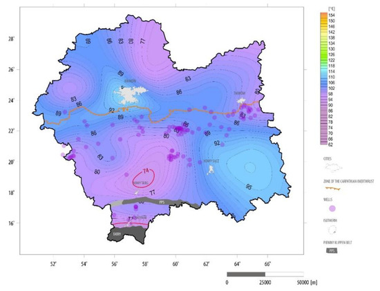
Figure 6.
Distribution of temperature at a depth of 3000 m b.g.s. in Małopolskie Voivodeship.
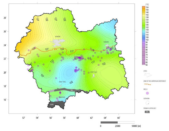
Figure 7.
Distribution of temperature at the depth of 4000 m b.g.s. in Małopolskie Voivodeship.
Rock mass temperatures exceeding 74 °C were observed throughout the Małopolskie Voivodeship at a depth of over 2000 m. The highest temperature can be observed in the Upper Silesian Coal Basin (above 140 °C at a depth of 4000 m) and bordering with that basin, in the Carpathian Foredeep (over 130 °C at a depth of 4000 m), as well as in the south-western part of the Western Carpathians, 120 °C at a depth of 4000 m). The temperatures of the Central Carpathians and the north–eastern part of the Carpathian Foredeep are the least favourable. Despite the most favourable temperature distribution in the Upper Silesian Coal Basin, geothermal waters at temperatures from 20 to 100 °C, the flow does not exceed 40 m3/h [36], which from the point of view of the minimum performance criterion of 100 m3/h, eliminates this area from further analysis. However, the area is characterized by high temperatures at a depth of 4000 m, which exceeds 140 °C, giving the basin an opportunity to consider using enhanced geothermal system (EGS) technology. In the area of the Upper Silesian Coal Basin, compact crystalline complexes have been found at a depth of over 3000 m, which are mostly Precambrian igneous rocks [51]. In addition, there is the possibility of using prospective sedimentary structures, which in the area of the Upper Silesian Coal Basin are carbonite [52]. Unfortunately, the area within the Małopolskie Voivodeship is poorly surveyed by deep boreholes.
In the case of the Silesian–Kraków Monocline, the possibility of exploitation of geothermal waters is limited by poor recognition of the geothermal conditions of the Palaeozoic. Younger Mesozoic layers are characterized by temperatures of geothermal waters not exceeding 20 °C [12] and are too low to be considered for the purposes of electricity generation. As in the case of the thermal conditions of the Upper Silesian Coal Basin, the area of the Silesian-Kraków Monocline is characterized by temperature at a depth of 4000 m of 130 °C, which allows one to analyze the possibility of using hot dry rock structures for energy purposes. However, no deep drilling (> 3,000 m) has been made in the Małopolskie Voivodeship. In the present state of hydrogeological and thermal knowledge, the prospect of using geothermal energy for energy purposes is solely via heat pumps, which, however, do not allow the generation of electricity.
Within the Miechów Trough, the occurrence of geothermal waters has been observed with temperatures of up to 102 °C and a flow rate typically not exceeding 20 m3/h [27]. On the other hand, a Miocene reservoir could be interesting—with a maximum temperature at 76 °C and a flow rate of several to locally 120 m3/h [24]. The high temperatures of the geothermal waters in the Miechów Trough do not correlate with the flow rates, as is the case of the Słomniki IG-1 (depth of 2332.2 m, drilled in 1961). It is characterized by a potentially high productivity of over 100 m3/h but the geothermal water temperature is 18 °C [40]. Temperatures in the area of the Miechów Trough at a depth of 4000 m have a range from 110 °C to 120 °C, but finding out if this area has potential for using EGS requires additional geological survey, which results directly from the lack of deep drilled boreholes.
In spite of locally relatively high temperatures of geothermal waters found in the area of the Carpathian Foredeep, up to 90 °C, the problem of their use for energy purposes is the low flow rate, not exceeding a dozen m3/h [24]. The western part of the Carpathian Foredeep, which borders the Upper Silesian Coal Basin, is characterized by high temperatures of the order of 130–135 °C at a depth of 4000 m, which may be an interesting prospect in the context of the implementation of EGS technology. However, the prospective zone is poorly surveyed by deep boreholes—only two boreholes exceeding 3000 m can be identified: Piotrowice 1 (3072.7 m, drilled in 1969) and Spytkowice 200 (3176.3, drilled in 1968). In the temperature zone of 120 °C there are also other boreholes: Wysoka 3 (2755.0 m, drilled in 1990) and Głogoczów IG-1 (3800.0 m, drilled in 1974).
The Western Carpathians are the most extensive of the areas analyzed. The temperatures of geothermal waters are in the range of 20–130 °C, but temperatures above 80 °C occur only in the area of the Podhale Basin. This is also the only area where the flow rate is associated with relatively high temperatures and ranges from tens of cubic meters, to a maximum of 550 m3/h [45]. Additional attention should be paid to the south-western part of the Western Carpathians within the Małopolskie Voivodship, where the temperatures at a depth of 4000 m are about 120 °C. One of the deep drilling boreholes is located in this area—Siekierczyna IG-1 (4809.9 m).
4.2. Thermodynamic Calculations for Selected Perspective Wells
Analysis of thermal data presented on the maps of deep temperature distribution allowed the most favorable thermal conditions from the point of view of electricity generation to be indicated. Taking into account potential geothermal reservoir capacity data in the Małopolska area, the following production wells were selected for further analysis: Bańska PGP-1, Bańska IG-1, Bańska PGP-3, Chochołów PIG-1. In addition, it was decided to analyze the Bukowina PGP-1 borehole, although its parameters did not meet the minimum temperature and performance criteria. However, the purpose of calculations for this approach, as extremely unfavorable, was to show whether the initial assumptions were correct.
The production wells selected for detailed analysis are shown in Table 1. However, in future consideration may be given to the estimation of the potential power and energy production for areas where EGS technology can be used.

Table 1.
Geothermal wells selected for analysis of electricity generation in Małopolskie Voivodeship.
The analyses and calculations indicate that in the Małopolskie Voivodeship, existing boreholes and a potential geothermal reservoir can be identified, which under favorable conditions might be utilized for electricity generation. Technologies that might be considered in this respect are the Organic Rankine Cycle or the Kalina Cycle. Potential gross geothermal power, calculated for the selected geothermal wells, will not exceed 900 kW for ORC and 1.6 MW for the Kalina Cycle. In the case of gross electricity generation, the amount for ORC technology will not exceed 3.3 GWh, and in the Kalina Cycle will not exceed 6.3 GWh.
The results of the analysis presented in Table 2 show that, assuming use of the full geothermal flow rate, the highest gross power is obtained with the Bańska PGP-1 and it is 1568 kW (with an efficiency of 7%) in the most advantageous variants—assuming the use of the Kalina Cycle and 87% ammonia in the active mixture. Gross power above 500 kW (824 kW for a flow rate of 290 m3/h) is also available for the Bańska PGP-3. The calculations confirm the key implications for geothermal water generation of two parameters: temperature and flow rate. The Bańska PGP-1 and Bańska PGP-3 are both characterized by the highest geothermal water temperature, in both cases 86 °C and a flow rate of 550 m3/h and 290 m3/h, respectively.
Table 2.
Summary of thermodynamic calculations.
Among the technologies analyzed and the working factors, the results obtained for the Kalina Cycle with an ammonia/water mixture of 87% ammonia (Figure 8, Figure 9, Figure 10 and Figure 11) are the most advantageous. This applies to all the solutions analyzed. In contrast to the ORC system, the R245f and R134a dry working fluids are the most preferred for the selected organic working fluids.
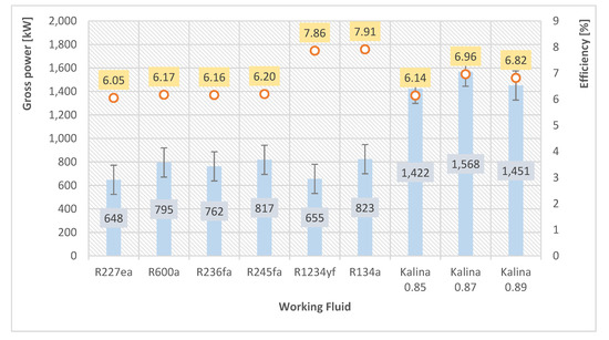
Figure 8.
Comparison of results for Bańska PGP-1, obtained for power and efficiency depending on the working fluid.
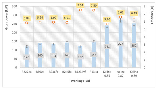
Figure 9.
Comparison of results for Bańska IG-1, obtained for power and efficiency depending on the working fluid.
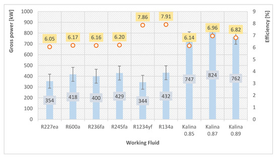
Figure 10.
Comparison of results for Bańska PGP-3, obtained for power and efficiency depending on the working fluid.
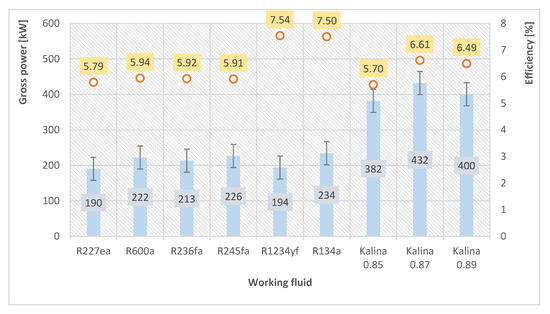
Figure 11.
Comparison of results for Chochołów PIG-1, obtained for power and efficiency depending on the working fluid.
As a major issue when implementing ORC and the Kalina Cycle in the geothermal water temperature range analyzed, the efficiency of the system does not exceed 10% and in most cases, it oscillates at a level of 6–7%. This is the effect of using geothermal waters for electricity generation with a temperature not exceeding 90 °C. The performance values for ORC rounded to the second decimal place are 6% for dry working fluids and 8% for wet working fluids. For the Kalina Cycle, the efficiency was calculated to be 6% for a mixture containing 85% ammonia, and 7% for mixtures containing 87% and 89% ammonia.
It is true, however, that as far as power plants are concerned, and they are possible with both systems, the power of the Kalina Cycle is significantly higher. In the case of ORC systems, the largest possible gross power of 823 kW (R134a) for the Bańska PGP-1 is 48% lower than the maximum gross power for the Kalina Cycle, which is 1568 kW (with a mixture ammonia content of 87%). This is primarily due to the differential pressure of the working medium on the turbine, indicating the need for further pressure optimization in the case of the Kalina Cycle, but not in terms of an increase in power output but rather in terms of the life of the plant. The calculated results refer to the use of the maximum geothermal water flow and represent the total potential for electricity generation.
5. Discussion
Due to the growing range of the population in the world, and thus the increase in the demand for electricity, it is necessary to search for solutions based on renewable energy sources, including low enthalpy geothermal energy. In addition, besides renewable energy, an important role in the future will be the full use of waste heat. Both of the mentioned heat sources can be used to generate electricity using ORC or Kalina Cycle technology [53,54,55]. This is important from an ecological point of view, as well as from an economic and geopolitical one (diversification of energy sources).
In the case of ORC technology, it can be stated that it confirmed its usefulness for low-temperature heat sources [53]. This is due to the relatively simple system configuration, its reliability and flexibility. Kalina’s Cycle, despite the greater complexity resulting from the use of a heterogeneous mixture as a working fluid, can be characterized by higher power obtained in the case of low enthalpy geothermal sources [56]. This is confirmed by the research results presented in this article. The power obtained for the Kalina Cycle is about 40% higher than for ORC, with a similar level of efficiency. The results present by Yari et al. [57] confirm the possibility of obtaining greater output power from the Kalina Cycle, as well as the tests carried out by Rodriguez et al. [58] obtained a result by 18% higher than ORC. The discrepancy between the results presented in this article and obtained by Rodriguez et al. [58] probably results from the working fluid used (for ORC, it was R-290, and the ratio of ammonia to water was 84%). In addition, they can be determined by the temperature on the heat source side, which is confirmed by the results obtained by Fiaschi et al. [59]. Authors of this publication compared sources with temperatures of 120 °C and 212 °C, obtaining a result by 25% for the variant with lower temperature in favor of the Kalina Cycle and a result by 4% worse for the variant with 212 °C. Therefore, Knapek’s (2007) [60] statement confirms that the Kalina Cycle is about 25% more effective than ORC. This may indicate a growing disproportion in the powers obtained for the decreasing temperature on the heat source side, in this case—geothermal water.
One should agree with the statement that in the case of ORC the working fluid used plays a key role in the case of energy conversion efficiency [53]. This is one of the few issues that the system designer influences from the point of view of obtaining optimal thermodynamic conditions [61,62,63]. Among other aspects, for this reason, the research presented in this article analyzes six different organic working fluids and three ammonia-water mixtures.
In addition to the results of efficiency, power and energy obtained, it should be noted that the nominal pressure on the turbine in the case of ORC is lower than in the case of the Kalin Cycle. The consequence of this may be a higher level of costs associated with sealing the installation based on the Kalina Cycle [53]. Another issue is the proportion of the ammonia-water mixture. It should be stated that the higher it is, the greater the energy efficiency, which is confirmed by the research carried out in the work.
The potential for electricity generation for the analyzed area was determined based on the use of available geothermal water resources. However, it should be mentioned that the globally developing EGS technology, using the heat of hot dry rocks, may in the future be an interesting prospect in places where the occurrence of high temperatures does not correspond to the possibility of obtaining sufficiently high efficiency of geothermal water extraction [51,52,64,65]. It does not change the fact that including the availability of low-temperature geothermal resources and their potential, ORC and the Kalina Cycle are currently the technologies with the largest scope of implementation [66,67].
Poland has a geothermal energy resource which could not only be used in the heating sector (geothermal district heating, heat pumps) but also for electricity generation. However, the development of the geothermal energy sector in Poland is limited by barriers such as: lack of the appropriate legal regulations and financial conditions, long and complicated legal and administrative procedures and low awareness of geothermal energy in society. In addition, it should be noticed the formal issues that not only concern Poland, but the ubiquitous applications using geothermal energy, such as the Geothermal Reporting Code [68,69]. It is also clear that for further successful progress in the use of geothermal energy in Poland it is necessary to reduce investment costs to make geothermal energy more competitive compared to fossil fuels [70,71,72]. It is extremely important to take into account the fact that electricity, as well as heat generated using geothermal energy, is considered as ecological. It has no impact on the stage of negative emissions resulting from the conventional fuel combustion processes, which contributes to the development especially in the rural region. This is important, deprived of heating and gas network infrastructure, for those communities where the use of geothermal resources may be a solution to limiting the negative impact of fossil fuels on the environment [73]. However, it should be taken into account that geothermal installations can potentially affect the natural environment, among others due to the drilling process—geological hazards, freshwater use, emission into the water, solid waste, land use, noise emission, light emission and impact on biodiversity. As mentioned above, this does not change the fact that geothermal energy is stable and ecological energy sources compared to other energy carriers.
6. Conclusions
- In the context of the growing demand for electricity in the world, it is necessary to search for solutions that would allow the use of unused energy resources.
- Geothermal energy as a stable source, under certain thermal and hydrological conditions, complement the energy mix in the context of electricity generation.
- Research presented in this article has shown that the Kalina Cycle allows obtaining greater gross power than ORC, up to 40%.
- The efficiency of thermal energy conversion into electricity is similar for the Kalina Cycle and ORC.
- The analysis and calculations show that in the area of Małopolskie Voivodeship existing geothermal wells and reservoirs that demonstrate the potential for electricity generation can be identified.
- Among the analyzed locations, the most favorable conditions were found in the Podhale geothermal system (especially the geothermal wells: Bańska PGP-1 and Bańska PGP-3).
- The potential gross power of a geothermal power plant, calculated for selected geothermal wells (assuming the use of the full geothermal water flow rate), will not exceed 900 kW for the Organic Rankine Cycle and 1600 kW for the Kalina Cycle.
Author Contributions
Conceptualization, M.K. and B.T.; Methodology, M.K., B.T. and L.P.; Formal analysis, M.K. and B.T.; Resources, M.K.; Data curation, M.K.; Writing—original draft preparation, M.K.; Writing—review and editing, M.K., B.T. and L.P.; Visualization, M.K.; Supervision, B.T. All authors have read and agreed to the published version of the manuscript.
Funding
The research was funded under the AGH-UST statutory research grant No. 16.16.140.315/05.
Conflicts of Interest
The authors declare no conflict of interest.
References
- European Parliament. A Policy Framework for Climate and Energy in the Period from 2020 to 2030; European Parliament: Brussels, Belgium, 2014. [Google Scholar]
- REN21. Renewables 2019 Global Status Report; REN21: Paris, France, 2019. [Google Scholar]
- Operacz, A.; Tomaszewska, B. The review of Polish formal and legal aspects related to hydropower plants. Environ. Sci. Pollut. Res. 2016, 23, 18953–18959. [Google Scholar] [CrossRef] [PubMed]
- Bloomberg New Energy Finance. New Energy Outlook 2019, Executive Summary; Bloomberg: New York, NY, USA, 2019. [Google Scholar]
- Kaczmarczyk, M. Methodology and impact categories of environmental life cycle assessment in geothermal energy sector. E3S Web Conf. 2019, 100, 32. [Google Scholar] [CrossRef]
- Kaczmarczyk, M. Potential of existing and newly designed geothermal heating plants in limiting of low emissions in Poland. E3S Web Conf. 2018, 44, 62. [Google Scholar] [CrossRef]
- DiPippo, R. Geothermal Power Plants: Designs and selection guidelines. In Proceedings of the World Geothermal Congress, Antalya, Turkey, 24–29 April 2005. [Google Scholar]
- Bertani, R. Geothermal Power Generation in the World 2010–2014 Update Report. In Proceedings of the World Geothermal Congress 2015, Melbourne, Australia, 19–25 April 2015. [Google Scholar]
- Barbacki, A. Classification of geothermal resources in Poland by exergy analysis—Comparative study. Renew. Sustain. Energy Rev. 2012, 16, 123–128. [Google Scholar] [CrossRef]
- DiPippo, R. Geothermal Power Plants: Principles, Applications, Case Studies and Environmental Impact; Library of Congress Cataloging-in-Publication Data; Elsevier Ltd.: Amsterdam, The Netherlands, 2012. [Google Scholar]
- Kalina, A.I.; Lebowitz, H.M. System Design and Experimental Development of the Kalina Cycle Technology. In Proceedings of the Ninth Annual Industrial Energy Technology Conference, Houston, TX, USA, 16–18 September 1987. [Google Scholar]
- Mirolli, M.; Hjartarson, H.; Mlcak, H.A.; Ralph, M. Testing and Operating Experience of the 2 MW Kalina Cycle Geothermal Power Plant in Húsavík, Iceland. Power Plant: Operation, Maintenance and Materials. Issue OMMI Internet J. 2002, 1, 2. [Google Scholar]
- Bujakowski, W.; Tomaszewska, B. (Eds.) Atlas Wykorzystania Wód Termalnych do Skojarzonej Produkcji Energii Elektrycznej i Cieplnej Przy Zastosowaniu Układów Binarnych w Polsce; Instytut Gospodarki Surowcami Mineralnymi i Energią Polskiej Akademii Nauk: Kraków, Poland, 2014. [Google Scholar]
- Nowak, W.; Borsukiewicz-Gozdur, A.; Klonowicz, P.; Stachel, A.; Hanausek, P.; Klonowicz, W. Wstępne wyniki badań prototypowego układu minisiłowni z ORC zasilanej wodą o temperaturze 100 °C. Przegląd Geol. 2010, 7, 622–625. [Google Scholar]
- Barbacki, A.; Pająk, L. Assessment of possibilities of electricity production in flash geothermal system in Poland. Geomat. Environ. Eng. 2017, 11, 17–29. [Google Scholar] [CrossRef][Green Version]
- Brasz, L.J.; Bilbow, W.M. Ranking of Working Fluids for Organic Rankine Cycle Applications. In Proceedings of the International Refrigeration and Air Conditioning Conference, Purdue University, West Lafayette, IN, USA, 12–15 July 2004. [Google Scholar]
- Borsukiewicz-Gozdur, A.; Nowak, W. Desirable Thermophysical Properties of Working Fluids in Organic Rankine Cycle. In Proceedings of the European Geothermal Congress 2007, Unterhaching, Germany, 30 May–1 June 2007. [Google Scholar]
- Boruskiewicz-Gozdur, A.; Nowak, W.; Wiśniewski, S. Zastosowanie nowych technologii do skojarzonego wytwarzania energii z wykorzystaniem energii geotermalnej dla potrzeb energetyki rozproszonej. In Atlas Geotermalny Karpat Wschodnich; Górecki, W., Ed.; Akademia Górniczo-Hutnicza im. S. Staszica: Kraków, Poland, 2013. [Google Scholar]
- Akbari, M.; Mahmoudi, S.; Yari, M.; Rosen, A. Energy and Exergy Analyses of a New Combined Cycle for Producing Electricity and Desalinated Water Using Geothermal Energy. Sustainability 2014, 6, 1796–1820. [Google Scholar] [CrossRef]
- Kaczmarczyk, M. Impact of rock mass temperature on potential power and electricity generation in the ORC installation. E3S Web Conf. 2017, 24, 02007. [Google Scholar] [CrossRef]
- Lund, J.W. Chena Hot Springs—Low Temperature Power Plant Dedication; IGA NEWS Newsletter of the International Geothermal Association; International Geothermal Association: Reykjavik, Iceland, 2006. [Google Scholar]
- Mink, L.; Karl, B.; Karl, C. An Example of Small Scale Geothermal Energy Sustainability: Chena Hot Springs, Alaska. In Proceedings of the World Geothermal Congress 2015, Melbourne, Australia, 19–25 April 2015. [Google Scholar]
- Weber, J.; Ganz, B.; Schellschmidt, R.; Sanner, B.; Schulz, R. Geothemal Energy Use in Germany. In Proceedings of the World Geothermal Congress 2015, Melbourne, Australia, 19–25 April 2015. [Google Scholar]
- Barbacki, A.P.; Bujakowski, W.; Pająk, L. Atlas Zbiorników Wód Geotermalnych Małopolski; Wydawnictwo Instytutu Gospodarki Surowcami Mineralnymi i Energią PAN: Kraków, Poland, 2006. [Google Scholar]
- Górecki, W. (Ed.) Atlas Zasobów Geotermalnych Formacji Mezozoicznej Na Niżu Polskim; Akademia Górniczo-Hutnicza im. S. Staszica: Kraków, Poland, 2006. [Google Scholar]
- Szczepański, A.; Haładus, A.; Hajto, M. Metodyka analizy podstawowych parametrów hydrogeologicznych zbiorników wód geotermalnych na Niżu Polskim. In Atlas Zasobów Geotermalnych Formacji Mezozoicznej Na Niżu Polskim; Górecki, W., Ed.; Akademia Górniczo-Hutnicza im. S. Staszica: Kraków, Poland, 2006. [Google Scholar]
- Szewczyk, J.; Gientka, D. Terrestrial heat flow density in Poland–A new approach. Geol. Q. 2009, 53, 123–140. [Google Scholar]
- Górecki, W. (Ed.) Atlas Zasobów Geotermalnych Polskich Karpat Zachodnich; Akademia Górniczo-Hutnicza im. S. Staszica: Kraków, Poland, 2011. [Google Scholar]
- Górecki, W. (Ed.) Atlas Geotermalny Zapadliska Przedkarpackiego; Akademia Górniczo-Hutnicza im. S. Staszica: Kraków, Poland, 2012. [Google Scholar]
- Galon, Z. SURFER Podręcznik Użytkownika; Gambit: Kraków, Poland, 2009. [Google Scholar]
- Borsukiewicz-Gozdur, A.; Nowak, W. Maximising the working fluid flow as a way of increasing power output of geothermal power plant. Appl. Therm. Eng. 2007, 27, 2074–2078. [Google Scholar] [CrossRef]
- Borsukiewicz-Gozdur, A.; Nowak, W.; Stachel, A. Systemy do generacji prądu elektrycznego przy wykorzystaniu wód geotermalnych–perspektywy rozwoju w Polsce. In Proceedings of the Materiały Ogólnopolskiego Kongresu Geotermalnego ”Geotermia w Polsce–doświadczenia, stan aktualny, perspektywy rozwoju”, Radziejowice, Poland, 17–19 października 2007. [Google Scholar]
- Guzović, Z.; Majcen, B.; Cvetkowić, S. Possibilities of electricity generation in the Republic of Croatia from medium-temperature geothermal sources. Appl. Energy 2012, 98, 404–414. [Google Scholar] [CrossRef]
- Znosko, J. (Ed.) Atlas Tektoniczny Polski; Państwowy Instytut Geologiczny: Warszawa, Poland, 1998.
- Plewa, S. Rozkład Parametrów Geotermalnych Na Obszarze Polski; Wydawnictwo CPPGSMiE, PAN: Kraków, Poland, 1994. [Google Scholar]
- Różkowski, A. Zapadlisko górnośląskie. In Hydrogeologia Regionalna Polski tom II. Wody Mineralne, Lecznicze I Termalne Oraz Kopalniane; Paczyński, B., Sadurski, A., Eds.; Państwowy Instytut Geologiczny: Warszawa, Poland, 2007. [Google Scholar]
- Małolepszy, Z. Low-enthalpy geothermal waters in coal-mines, Upper Silesia coal basin, Poland. In Proceedings of the World Geothermal Congress 2000, Kyushu-Tohoku, Japan, 28 May–10 June 2000. [Google Scholar]
- Burzewski, S.W. Strukturalne warunki jury olkusko-wolbromskiej jako brzegowe dla hydrodynamiki złóż naftowych niecki nidziańskiej. Kom. Nauk. Geol. PAN Pr. Geol. 1969, 61, 1–85. [Google Scholar]
- Kotlicki, S. Chemizm wód podziemnych południowo-zachodniej części niecki miechowskiej. Biul. Inst. Geol. 1971, 249, 65–133. [Google Scholar]
- Barbacki, A.P. Zbiorniki Wód Geotermalnych Niecki Miechowskiej i Środkowej Części Zapadliska Przedkarpackiego; Studia, Rozprawy, Monografie; Wydawnictwo Instytutu Gospodarki Surowcami Mineralnymi i Energią PAN: Kraków, Poland, 2004. [Google Scholar]
- Moryc, W. Katalog Wierceń Górnictwa Naftowego. Geonafta 1970, I, 3–4. [Google Scholar]
- Moryc, W. Katalog Wierceń Górnictwa Naftowego. Geonafta 1976, I, 5. [Google Scholar]
- Pich, J. Chemizm wód podziemnych w środkowej części zapadliska Przedkarpackiego. Biuletyn Instytutu Geologicznego 1978, 312, 129–190. [Google Scholar]
- Hajto, M.; Szewczyk, J. Analiza termiczna obszaru zapadlisko Przedkarpackiego. In Atlas Geotermalny Zapadliska Przedkarpackiego; Górecki, W., Ed.; Akademia Górniczo-Hutnicza im. S. Staszica: Kraków, Poland, 2012. [Google Scholar]
- Kępińska, B. Warunki Termiczne i Hydrotermalne Podhalańskiego Systemu Geotermalnego; Studia, Rozprawy, Monografie, Zeszyt 135; Wydawnictwo IGSMiE PAN: Kraków, Poland, 2006. [Google Scholar]
- Kępińska, B. Historia badań i wykorzystania wód geotermalnych. In Atlas Zasobów Geotermalnych Polskich Karpat Zachodnich; Górecki, W., Ed.; Akademia Górniczo-Hutnicza im. S. Staszica: Kraków, Poland, 2011. [Google Scholar]
- Chowaniec, J.; Zuber, A.; Ciężkowski, W. Prowincja karpacka. In Hydrogeologia Regionalna Polski Tom II. Wody Mineralne, Lecznicze I Termalne Oraz Kopalniane; Paczyński, B., Sadurski, A., Eds.; Państwowy Instytut Geologiczny: Warszawa, Poland, 2007. [Google Scholar]
- Tomaszewska, B.; Bielec, B.; Miecznik, M. Ocena uwarunkowań hydrogeotermalnych dla uzdatniania części schłodzonych wód termalnych. Model koncepcyjny systemu geotermalnego Podhala. Przegląd Geol. 2015, 63, 1115–1121. [Google Scholar]
- Bujakowski, W.; Tomaszewska, B.; Miecznik, M. The Podhale geothermal reservoir simulation for long-term sustainable production. Renew. Energy 2016, 99, 420–430. [Google Scholar] [CrossRef]
- Oszczypko, N. Charakterystyka tektoniczna i geologiczna polskich Karpat Zachodnich. In Atlas Zasobów Geotermalnych Polskich Karpat Zachodnich; Górecki, W., Ed.; Akademia Górniczo-Hutnicza im. S. Staszica: Kraków, Poland, 2011. [Google Scholar]
- Bujakowski, W.; Barbacki, A.; Bielec, B.; Hołojuch, G.; Kasztelewicz, A.; Kępińska, B.; Miecznik, M.; Pająk, L.; Skrzypczak, R.; Tomaszewska, B. Obszary badawcze w masywach krystalicznych. In Ocena Potencjału, Bilansu Cieplnego i Perspektywicznych Struktur Geologicznych Dla Potrzeb Zamkniętych Systemów Geotermicznych (Hot Dry Rocks) w Polsce; Wójcicki, A., Sowiżdżał, A., Bujakowski, W., Eds.; Ministerstwo Środowiska: Warszawa/Kraków, Poland, 2013. [Google Scholar]
- Sowiżdżał, A.; Hajto, M.; Stefaniuk, M.; Targosz, P.; Kępińska, B.; Kiersnowski, H.; Jureczka, J.; Karwasiecka, M.; Wilk, S.; Rolka, M.; et al. Lokalizacja potencjalnych obszarów badawczych dla niekonwencjonalnych systemów geotermicznych (HDR/EGS) na obszarze Polski. In Ocena Potencjału, Bilansu Cieplnego i Perspektywicznych Struktur Geologicznych dla Potrzeb Zamkniętych Systemów Geotermicznych (Hot Dry Rocks) w Polsce; Wójcicki, A., Sowiżdżał, A., Bujakowski, W., Eds.; Ministerstwo Środowiska: Warszawa/Kraków, Poland, 2013. [Google Scholar]
- Nemati, A.; Nami, H.; Ranjbar, F.; Yari, M. A comparative thermodynamic analysis of ORC and Kalina cycles for waste heat recovery: A case study for CGAM cogeneration system. Case Stud. Therm. Eng. 2017, 9, 1–13. [Google Scholar] [CrossRef]
- Yari, M.; Mahmoudi, S.M. Utilization of waste heat from GT-MHR for power generation in organic Rankine cycles. Appl. Therm. Eng. 2010, 30, 366–375. [Google Scholar] [CrossRef]
- Yari, M.; Mahmoudi, S.M. A thermodynamic study of waste heat recovery from GT-MHR using organic Rankine cycles. Heat Mass Transf. 2011, 47, 181–196. [Google Scholar] [CrossRef]
- Walraven, D.; Laenen, B.; D’haeseleer, W. Comparison of thermodynamic cycles for power production from low-temperature geothermal heat sources. Energy Convers. Manag. 2013, 66, 220–233. [Google Scholar] [CrossRef]
- Yari, M.; Mehr, A.S.; Zare, V.; Mahmoudi, S.M.; Rosen, M.A. Exergoeconomic comparison of TLC (trilateral Rankine cycle), ORC (organic Rankine cycle) and Kalina cycle using a low grade heat source. Energy 2015, 83, 712–722. [Google Scholar] [CrossRef]
- Rodríguez, C.E.C.; Palacio, J.C.E.; Venturini, O.J.; Lora, E.E.S.; Cobas, V.M.; dos Santos, D.M.; Dotto, F.R.L.; Giallucad, V. Exergetic and economic comparison of ORC and Kalina cycle for low temperature enhanced geothermal system in Brazil. Appl. Therm. Eng. 2013, 52, 109–119. [Google Scholar] [CrossRef]
- Fiaschi, D.; Manfrida, G.; Rogai, E.; Talluri, L. Exergoeconomic analysis and comparison between ORC and Kalina cycles to exploit low and medium-high temperature heat from two different geothermal sites. Energy Convers. Manag. 2017, 154, 503–516. [Google Scholar] [CrossRef]
- Knapek, E.; Kittl, G. Unterhaching Power Plant and Overall System. In Proceedings of the European Geothermal Congress 2007, Unterhaching, Germany, 30 May–1 June 2007. [Google Scholar]
- Kang, Z.; Zhu, J.; Lu, X.; Li, T.; Wu, X. Parametric optimization and performance analysis of zeotropic mixtures for an organic Rankine cycle driven by low-medium temperature geothermal fluids. Appl. Therm. Eng. 2015, 89, 323–331. [Google Scholar] [CrossRef]
- Liu, B.; Chien, K.; Wang, C. Effect of working fluids on organic Rankine cycle for waste heat recovery. Energy 2004, 29, 1207–1217. [Google Scholar] [CrossRef]
- Yue, C.; Han, D.; Pu, W.; He, W. Thermal matching performance of a geothermal ORC system using zeotropic working fluids. Renew. Energy 2015, 80, 746–754. [Google Scholar] [CrossRef]
- Beardsmore, G.R.; Rybach, L.; Blackwell, D.; Baron, C. A protocol for estimating and mapping global EGS potential. Geotherm. Resour. Counc. Trans. 2010, 34, 301–312. [Google Scholar]
- Chamorro, C.; García-Cuesta, J.L.; Mondejar, M.E.; Pérez-Madrazo, A. Enhanced geothermal systems in Europe: An estimation and comparison of the technical and sustainable potentials. Energy 2014, 65, 250–263. [Google Scholar] [CrossRef]
- Hurter, S.; Haenel, R. Atlas of Geothermal Resources in Europe; Office for the Official Publications of the European Communities: Luxembourg, 2002.
- Hurter, S.; Schellschmidt, R. Atlas of geothermal resources in Europe. Geothermics 2003, 32, 779–787. [Google Scholar] [CrossRef]
- Toohey, B.; Diebert, L.; Thompson, A.; Yang, D.; Hjartarson, A. The Canadian Geothermal Code for Public Reporting; Canadian Geothermal Energy Association: Calgary, AB, Canada, 2010. [Google Scholar]
- Lawless, J. The Geothermal Reporting Code: Australian Code for Reporting of Exploration Results, Geothermal Resources and Geothermal Reserves, 2nd ed.; Australian Geothermal Energy Group (AGEG) and the Australian Geothermal Energy Association (AGEA): Adelaide, Australia, 2010. [Google Scholar]
- Kępińska, B. Current geothermal activities and prospects in Poland—An overview. Geothermics 2003, 32, 397–407. [Google Scholar] [CrossRef]
- Kępińska, B. Current state and prospects of geothermal energy implementation in Poland. Appl. Energy 2003, 74, 43–51. [Google Scholar] [CrossRef]
- Igliński, B.; Buczkowski, R.; Kujawski, W.; Cichosz, M.; Piechota, G. Geoenergy in Poland. Renew. Sustain. Energy Rev. 2012, 16, 2245–2557. [Google Scholar] [CrossRef]
- Kaczmarczyk, M.; Sowiżdżał, A.; Tomaszewska, B. Energetic and Environmental Aspects of Individual Heat Generation for Sustainable Development at a Local Scale—A Case Study from Poland. Energies 2020, 13, 454. [Google Scholar] [CrossRef]


© 2020 by the authors. Licensee MDPI, Basel, Switzerland. This article is an open access article distributed under the terms and conditions of the Creative Commons Attribution (CC BY) license (http://creativecommons.org/licenses/by/4.0/).