Article

Analytical Modeling of Neutral Point Current in T-type Three-level PWM Converter

Department of Electrical Engineering, Korea National University of Transportation, Chungju 27469, Korea
Energies 2020, 13(6), 1324; https://doi.org/10.3390/en13061324
Submission received: 29 January 2020 / Revised: 28 February 2020 / Accepted: 9 March 2020 / Published: 12 March 2020
(This article belongs to the Section F: Electrical Engineering)

Abstract

:
Since a T-type three-level PWM converter has several intrinsic advantages, it has been researched for various applications such as grid-connected converter systems. However, it necessarily requires an additional voltage control loop for balancing the upper and the lower DC-link voltage. To satisfy this requirement, an offset voltage is widely used to provide a neutral point current without affecting other variables such as total DC-link voltage and three-phase input current. However, these methods are mostly based on the averaged value between the applied offset voltage and the neutral point voltage or current, and there is no exact analytical model. Therefore, in this paper, the exact theoretical relationship between the offset voltage and the neutral point current is analyzed. This result can be expected to be useful for an effective voltage balancing control loop design as well as the better understanding of the whole system operation. The validity of the obtained analytical model is verified by simulation and experimental results.

1. Introduction

Since a T-type three-level PWM converter can generate multi-level output voltage waveforms compared to a conventional two-level PWM converter, it has an advantage in terms of the harmonic reduction. Furthermore, compared to the neutral-point-clamped (NPC) three-level PWM converter [1], the T-type three-level PWM converter has two diodes less per bridge leg. Since the NPC three-level topology was originally developed for medium voltage applications, the switching devices are connected in series to overcome the limited voltage blocking capability of the available devices, and it is related to the increased conduction losses. However, for low voltage applications, the switching devices does not need to be connected in series anymore. Hence, during the positive (P) or negative (N) switching states, only one switching device is conducted, and the reduced conduction losses make the T-type three-level topology the preferred choice for low voltage applications [2]. Therefore, various research has attempted to apply the T-type three-level PWM converter to many applications [2,3,4,5,6,7].
However, the T-type three-level PWM converter requires necessarily the relevant neutral point voltage control loop for stable operation. According to the different applications, it performs various balanced voltage controls between the upper and the lower DC-link voltage [3,8]. To satisfy this requirement, an offset voltage is widely used to provide some neutral point current values which are normally zero in balanced load conditions. Since the offset voltage affects only the difference between the upper and the lower DC-link voltage, it does not disrupt other control variables such as the total DC-link voltage and three-phase input current. Therefore, to control effectively the neutral point voltage or current, it is necessary to understand how the offset voltage works, that is the analytical relationship between the offset voltage and the neutral point voltage or current. However, the conventional research normally used the averaged neutral point current-based neutral point voltage control [3,4] and a predictive method to apply the optimal voltage vector in a selective manner for minimizing the difference of each DC-link voltage [5,6,7,8]. Specifically, in [9], a novel model predictive control to eliminate common-mode voltage is proposed. By considering dead-time effects on common-mode voltage, different voltage vectors were utilized, and it was mentioned ambiguously these vectors also can balance the neutral point voltage. In [10], a three-level T-type neutral-point-clamped indirect matrix converter with novel SVPWM methods is proposed. However, for the neutral-point voltage balancing, two isolated front active rectifier stages with simple algorithm were used to control the upper and lower DC-link voltage independently. Hence, it does not require any voltage balancing control within T-type converter. In [11], a five-level T-type cascade converter for photovoltaic systems was proposed. To implement the voltage balancing control, a simple PI controller was used based on the voltage error input between the upper and lower capacitor to change the modulation index in vertical axis; however, there was no analytical model about that. In [12], a three-phase transformerless T-type multilevel inverter for photovoltaic application was proposed, and a novel hysteresis space vector current control (HSVCC) scheme was used to mitigate the common-mode leakage current and assure capacitor balancing; however, there was no specific explanation how the HSVCC scheme affects the capacitor balancing. In [13], the simplified model predictive control for a T-type inverter was proposed, and the predicted neutral point voltage was used just to select the suitable small vectors without the weighting factor in the cost function for balancing capacitor voltages with reduced execution time. In summary, research about an exact analytical model for the neutral point current has not been presented.
Therefore, this paper proposes the exact analytical modeling for the neutral point current in the T-type three-level PWM converter by using the given system parameters, such as the duty cycle for PWM operation, the grid-side three-phase input current, and the output DC-link voltage based on system operational conditions. Compared to the conventional approach, this paper presented the modeling of neutral point current in an instantaneous manner, not averaged. Moreover, by using the proposed model, it is possible to obtain the average neutral current value by averaging the instantaneous neutral current value. This modeling analysis has been done under the space-vector PWM operation which is a widely adopted method due to the better DC-link voltage utilization. The validity of the obtained mathematical expression for the neutral point current is verified through simulation and experimental results.

2. T-Type Three-Level PWM Converter

2.1. Circuit Configuration

Figure 1 shows the T-type three-level PWM converter system for grid-connected applications. On the AC side, the three-phase voltage source is connected to the output of the T-type three-level PWM converter through an inductor L filter including an equivalent series resistance R. On the DC side, it is assumed that two independent loads are connected to each DC-link voltage (vH and vL). In the balanced condition that each load has a same value, the voltage across each DC-link capacitor C becomes half of the total DC-link voltage vDC. However, in the unbalanced condition that each load has a different value, each DC-link voltage deviates from the original value, and it affects the overall system operations such as power quality and system protection. Hence, in order to prevent these issues and maintain stable operations, a relevant neutral point voltage control scheme based on the offset voltage is required, and in other words, it has to be known how the offset voltage affects the neutral point current io.

2.2. Modeling of Neutral Point Current

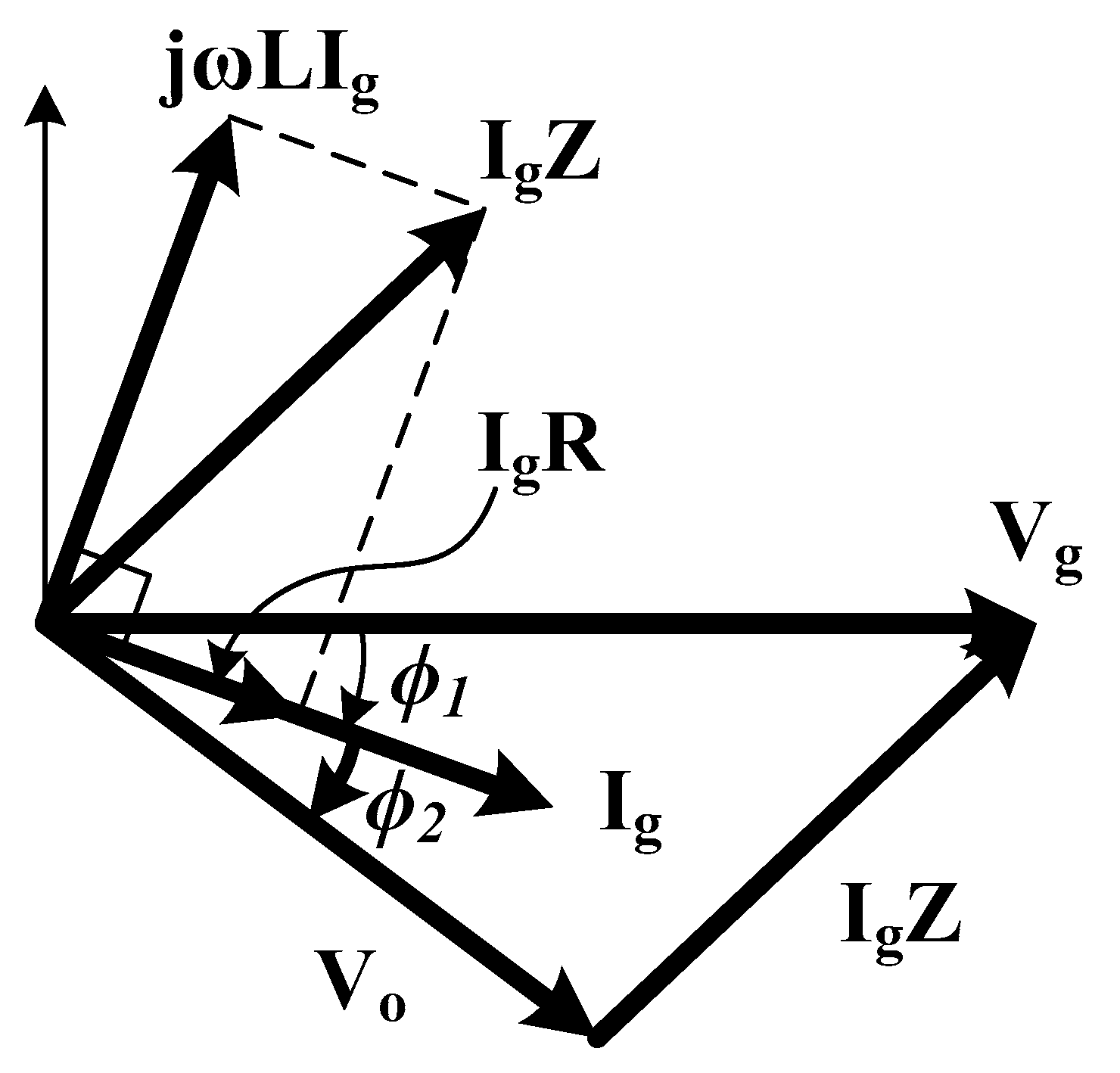
To control the neutral point current effectively, the analytical model for the neutral point current should be obtained. To simplify the analysis, it is assumed that each DC-link voltage is well regulated equivalently (vH = vL = 0.5 × vDC), and three-phase variables are all balanced. Figure 2 shows the phasor diagram of the T-type three-level PWM converter operation. For the unity power factor control in grid-connected applications, the grid current (Ig) is normally controlled to be synchronized with the grid voltage (Vg), but the Φ1 phase delay is assumed for a more general analysis. To operate with this condition, the output voltage (Vo) of the T-type three-level PWM converter should be additionally delayed by the Φ2 radian compared to the grid current.
This steady-state operation can also be presented in the time domain by Figure 3. Each three-phase sinusoidal grid current (iga, igb and igc) is given by (1), where Ip is the peak value, and the other three sinusoidal waveforms (da, db and dc) given by (2) are duties to generate the output voltage (voa, vob, and voc) by comparing with the carriers where the m is the modulation index (0 < m < 1).
i g a = I p cos ( ω t ϕ 1 ) i g b = I p cos ( ω t 2 π / 3 ϕ 1 ) i g c = I p cos ( ω t + 2 π / 3 ϕ 1 )
d a = m cos ( ω t ϕ 1 ϕ 2 ) d b = m cos ( ω t 2 π / 3 ϕ 1 ϕ 2 ) d c = m cos ( ω t + 2 π / 3 ϕ 1 ϕ 2 )
Further, the relational expression between the output voltage and the duty is given by (3).
v o x = 0.5 v D C d o x , ( x = a , b , c )
The duties in (2) are transformed to the novel duties for space vector modulation (SVM) due to the effective DC-link voltage utilization. The offset duty which aims to control the neutral point current should also be considered. Therefore, the final duties (doa, dob, and doc) are generated as shown at the bottom of Figure 3. First, each sector from I to VI is separated based on the zero point crossing of the final duties in one grid period, and then these six sectors are again classified as two subsectors (A and B) based on the reciprocal crossing of the corresponding two final duties. Therefore, the total number of sectors becomes 12, and each sector is not symmetric because of the added offset duty. The Δθ originating from the offset duty is the phase difference between the original and the final duties, and it can be calculated by (4), where dos is the offset duty.
Δ θ = π 2 cos 1 ( 2 3 d o s m )
Here, the SVM scheme presented in [14] is used, and for example, the final duties in sector I-A (θ1 < ωt < θ2) of Figure 3 are given by (5), where dxn(x = a, b, c) is the duties only including SVM method, and Vmax and Vmin are the highest and lowest duty in each sector, respectively.
d o a = d a n + d o s = m cos ( ω t ϕ 1 ϕ 2 ) 0.5 V D C ( V max + V min ) + d o s d o b = d b n + d o s = m cos ( ω t 2 π / 3 ϕ 1 ϕ 2 ) 0.5 V D C ( V max + V min ) + d o s d o c = d c n + d o s = m cos ( ω t + 2 π / 3 ϕ 1 ϕ 2 ) 0.5 V D C ( V max + V min ) + d o s
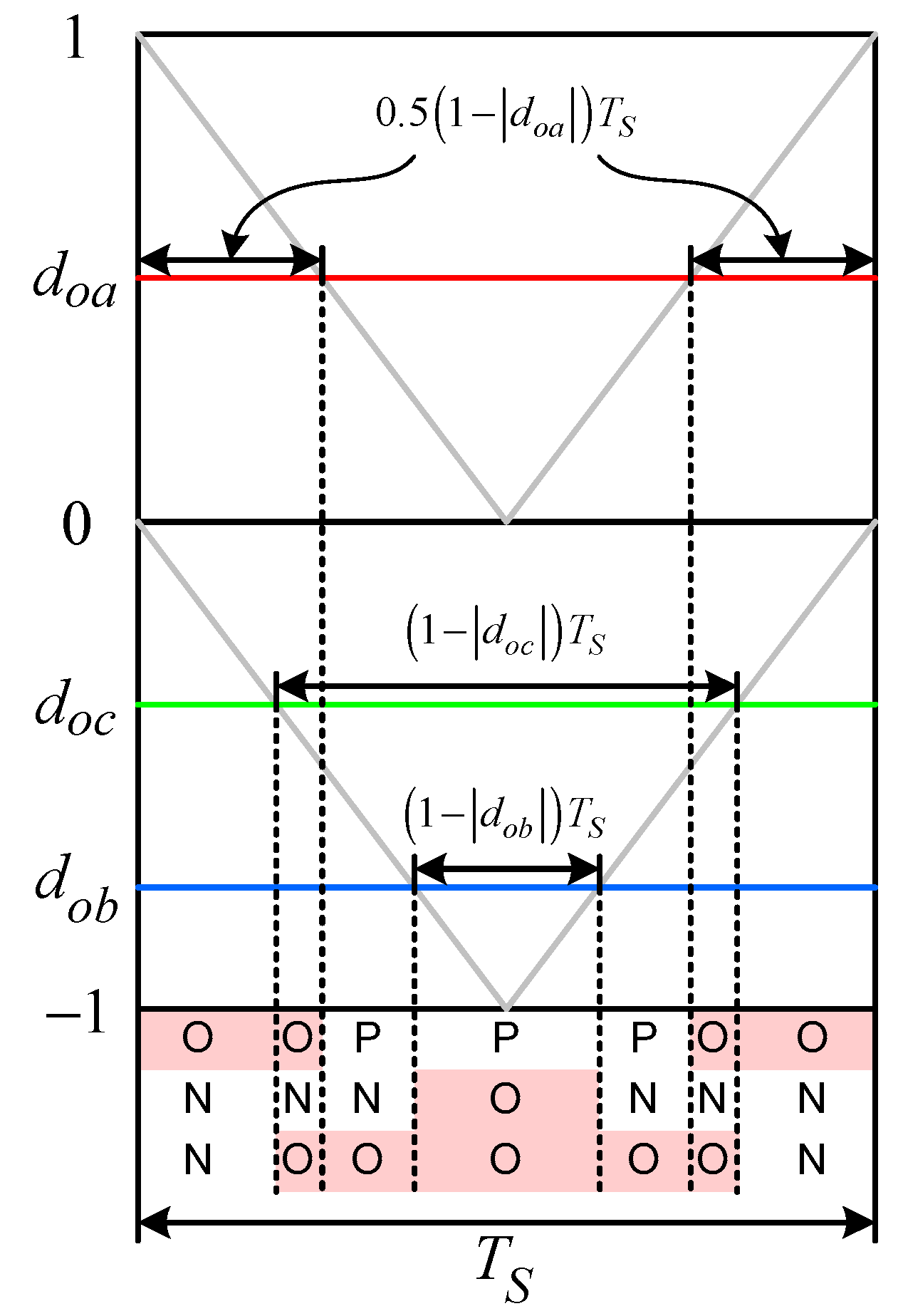
The analytical modeling of the neutral point current can be obtained by the switching state within each sector. The T-type three-level PWM converter has three switching states in each leg: 1) P state in which the upper two switches Sx1 and Sx2 are turned on; 2) O state in which the middle two switches Sx2 and Sx3 are turned on; and 3) N state in which the lower two switches Sx3 and Sx4 are turned on, where x = a, b, c. However, since the neutral point current flows only during the O state, the neutral point current can be calculated by using the O state duration time and the corresponding grid current in each phase. Figure 4 shows one example of the O state duration time in sector I-A of Figure 3 during one sampling period Ts. Although the polarity of the duties continuously changes across each sector, the mathematical expression about the O state duration time within Ts is identical regardless of that polarity, and it can be applied to other sectors in the same way. For the sector I-A, the neutral point current can be obtained as (6), and Table 1 summarizes the mathematical expression for all sectors, where the variables α1, α2, α3, β1, β2, and β3 are given in Appendix A (A1). From Table 1, if the system parameters are given, the exact neutral point current value can be obtained.
i o = ( 1 | d o a | ) i a + ( 1 | d o b | ) i b + ( 1 | d o c | ) i c = d o s ( 2 i a ) d a n i a + d b n i b + d c n i c = 2 d o s · I p cos ( ω t ϕ 1 ) + m · I p ( 3 2 s i n ( 2 ω t 2 ϕ 1 ϕ 2 π 3 ) + 3 4 cos ϕ 2 3 4 s i n ϕ 2 )
The average value of the neutral point current during one grid period can be calculated by (7), and it can be further simplified as (8) assuming the Δθ is zero which means the load condition is balanced (iH = iL). However, even under the unbalanced load condition, the Δθ is very small so that the assumption is reasonable.
i o _ a v g = 1 2 π k = 1 12 [ θ k θ k + 1 i o d ( ω t ) ] = 6 d o s · I p cos Δ θ · cos ϕ 2 π + m · I p 2 π ( 9 2 sin ( 2 · Δ θ ) · cos ϕ 2 9 · Δ θ · cos ϕ 2 )
i o _ a v g 6 d o s · I p cos ϕ 2 π
From (8), it can be concluded that the average neutral point current is proportional to the offset duty and is not related to the power factor because it only includes Φ2 but not Φ1.

3. Simulation and Experimental Results

To verify the obtained analytical model for the neutral point current in the T-type three-level PWM converter, a simulation and experimental tests were performed. The system parameters are summarized in Table 2.
Figure 5 shows the control block diagram of the T-type three-level PWM converter. The three-phase grid voltages (vga, vgb, vgc) were used for phase-locked loop (PLL) to detect the phase angle and frequency of the grid. The detected phase angle θ makes the abc-dq transform of three-phase grid voltages and currents for the synchronous reference frame control. In the inner loop, one current controller was used to regulate the three-phase grid current, and this can be implemented with simple proportional-integral (PI) control or some advanced control such as predictive control for the fast response. Here, the robust predictive control algorithm proposed in [15] was used. In the outer loop, two voltage controllers were used to regulate the total DC-link voltage vDC and the neutral point voltage ve, respectively. The total DC-link voltage controller can be implemented with simple PI control [16]. Furthermore, by using the mathematical expression about the DC-link side of the T-type three-level PWM converter in (9) and (10), the neutral point voltage control loop can be constructed by Figure 6. From this, the PI neutral voltage controller can be designed, and the output becomes the offset voltage and added to the output of the current controller to generate the final gate signals.
C d v H d t = i P v H R H C d v L d t = i n v L R L = i p + i o v L R L , ( i p + i o + i n = 0 )
v e = v H v L = ( R H S C R H + 1 R L S C R L + 1 ) i P R L S C R L + 1 i o
Figure 7 shows the simulation waveforms at the unity power factor (Φ1 = 0) operation under the unbalanced load conditions. The upper and lower loads were set as 100% and 80%, respectively. The Φ2 and the Δθ were calculated as 0.067 and 0.058 radian with a numerical method, respectively. Figure 7a,b show the average and the switching model-based waveforms, respectively. The average model corresponds with the analytical model obtained in this paper. The neutral point current io in Figure 7a follows exactly the expression in Table 1, and the average neutral point current value is about −1.6 [A]. In Figure 7b, although the actual neutral point current io becomes the pulsating waveform due to the switching operation, the averaged current waveform io_Ts calculated in every sampling period has almost same shape with the io in Figure 7a, and the average value for one grid period was similarly measured as −1.6 [A].
Figure 8 shows the simulation waveforms at the non-unity power factor (Φ1 = π/6) operation under the same unbalanced load conditions. The Φ2 and the Δθ were calculated as −0.456 and 0.056 radian with a numerical method, respectively. Figure 8a shows the average model-based waveforms, and this corresponds with the analytical model obtained in this paper. In this case, the average neutral point current value is also about −1.6 [A] corresponding to the same result with the Figure 7a. Hence, it can be verified that the average neutral point current value is not related to the power factor from (8). Figure 8b shows switching model-based waveforms. From the grid phase voltage and current, the non-unity power factor (Φ1 = π/6) operation can be identified. Furthermore, the averaged current waveform io_Ts calculated in every sampling period has almost same shape with the io in Figure 8a, and, inevitably, the average value for one grid period was similarly measured as −1.6 [A].
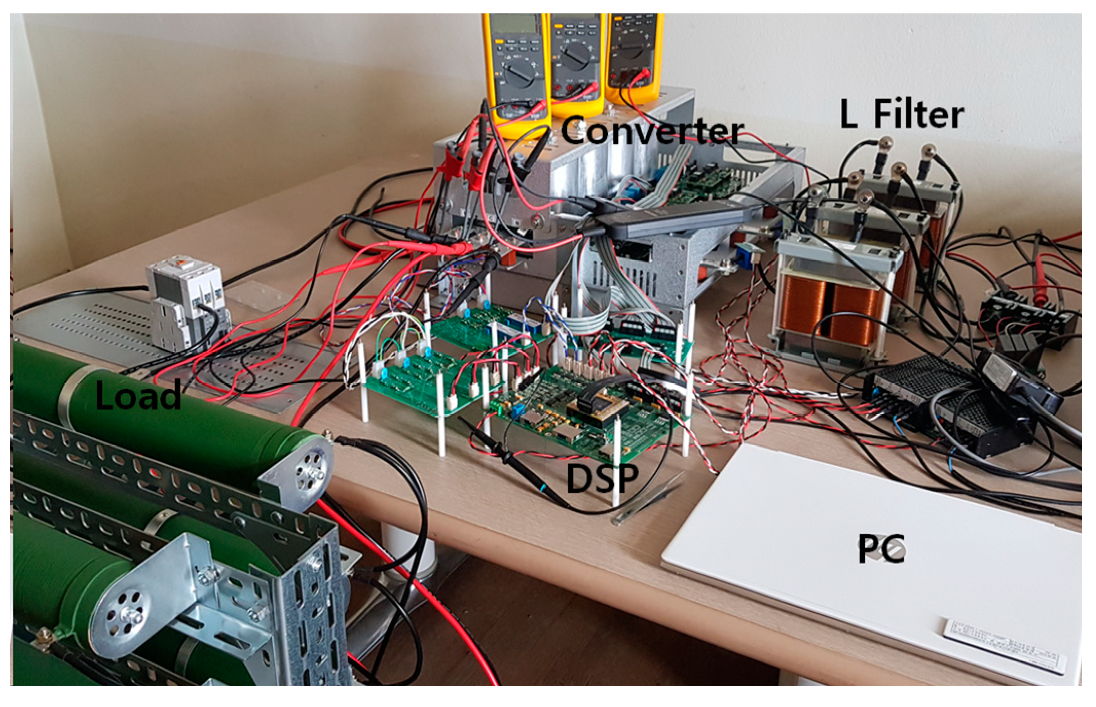
Figure 9 shows the experimental setup of the T-type three-level PWM converter system. For the implementation of the control algorithm, DSP TMS320F28335 was used.
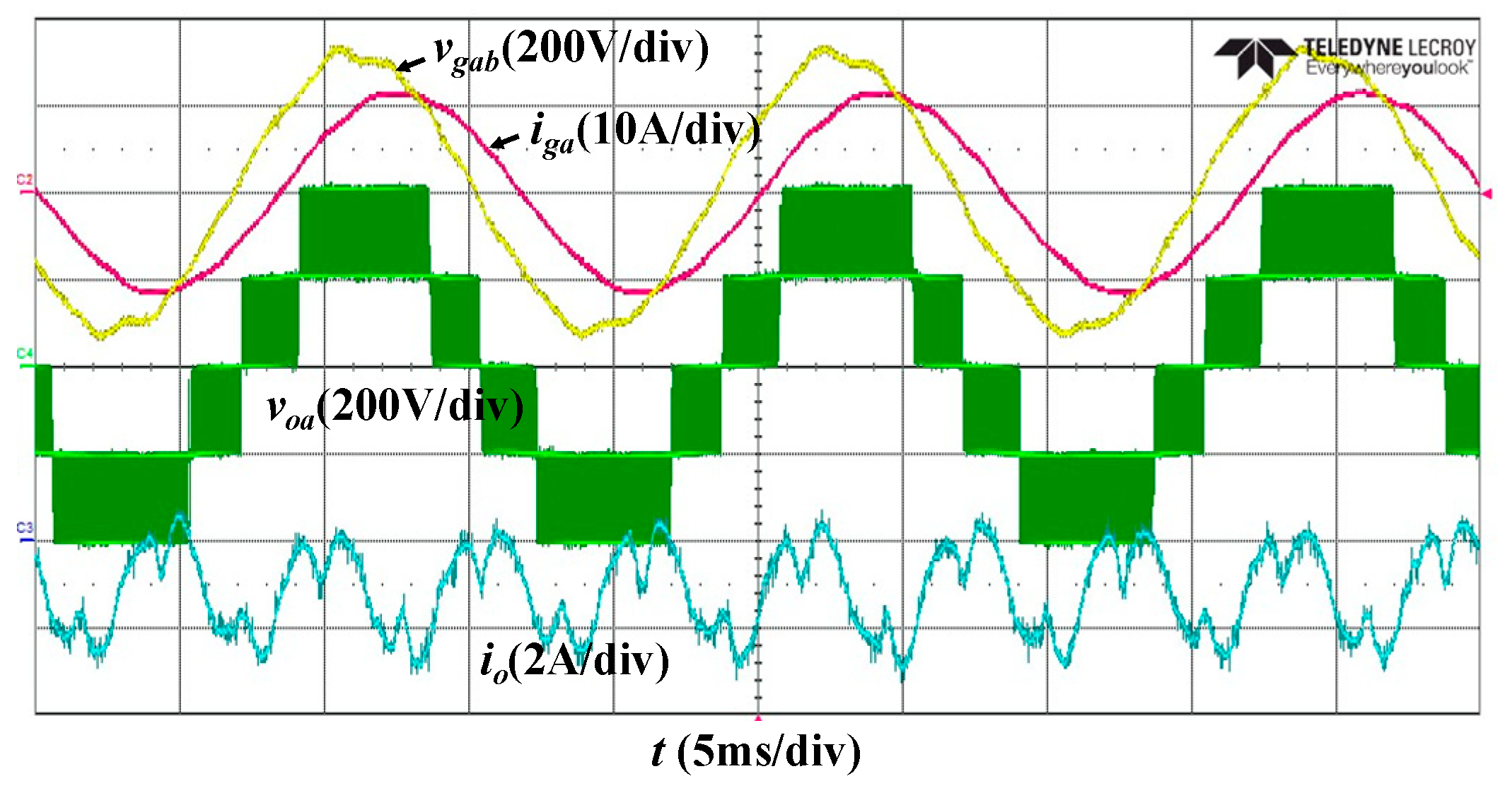
Figure 10 shows the experimental waveforms under the same unbalanced load conditions and unity-power factor operation. The grid phase current iga flows sinusoidally having the phase difference π/6 [rad] compared to the line-to-line grid voltage vgab. Hence, the unity-power factor operation is satisfied. From the converter’s PWM output voltage voa, it can be known that the upper and lower DC-link voltages are well regulated equivalently even if the load is unbalanced. Furthermore, the averaged neutral point current waveform io calculated in every sampling period was identified that it has similar waveform with the simulation result of io in Figure 7a. Hence, the obtained analytical model for the neutral point current was also verified by the experimental results.

4. Conclusions

This paper proposed an analytical model for the neutral point current in the T-type three-level PWM converter. The analysis was performed assuming the upper and lower DC-link voltages are well regulated equivalently even under unbalanced load conditions. The obtained analytical model for the neutral point current was verified by simulation and experimental results. This analytical model can be used for the neutral point voltage control loop design as well as the preliminary investigation about the whole system operation related to the neutral point voltage variation.

Funding

This work was supported by the Korea Institute of Energy Technology Evaluation and Planning (KETEP) and the Ministry of Trade, Industry & Energy (MOTIE) of the Republic of Korea (No. 20192010106690). This work was supported by the National Research Foundation of Korea (NRF) grant funded by the Korea government (MSIP; Ministry of Science, ICT & Future Planning) (No. 2017R1C1B5016982).

Conflicts of Interest

The author declares no conflict of interest.

Appendix A

α 1 = 2 d o s · I p cos ( ω t ϕ 1 ) α 2 = 2 d o s · I p cos ( ω t 2 π / 3 ϕ 1 ) α 3 = 2 d o s · I p cos ( ω t + 2 π / 3 ϕ 1 ) β 1 = ( 3 / 2 ) · sin ( 2 ω t 2 ϕ 1 ϕ 2 ) β 2 = ( 3 / 2 ) · sin ( 2 ω t 2 ϕ 1 ϕ 2 π / 3 ) β 3 = ( 3 / 2 ) · sin ( 2 ω t 2 ϕ 1 ϕ 2 + π / 3 )

References

  1. Nabae, A.; Takahashi, I.; Akagi, H. A new neutral-point-clamped PWM inverter. IEEE Trans. Ind. Appl. 1981, IA-17, 518–523. [Google Scholar] [CrossRef]
  2. Schweizer, M.; Kolar, J.W. Design and implementation of a highly efficient three-level T-type converter for low-voltage applications. IEEE Trans. Power Electron. 2013, 28, 899–907. [Google Scholar] [CrossRef]
  3. Park, Y.; Sul, S.-K.; Lim, C.-H.; Kim, W.-C.; Lee, S.-H. Asymmetric control of dc-link voltages for separate MPPTs in three-level inverters. IEEE Trans. Power Electron. 2013, 28, 2760–2769. [Google Scholar] [CrossRef]
  4. Alemi, P.; Jeung, Y.-C.; Lee, D.-C. DC-link capacitance minimization in T-type three-level AC/DC/AC PWM converters. IEEE Trans. Power Electron. 2015, 62, 1382–1391. [Google Scholar] [CrossRef]
  5. Lee, J.-S.; Lee, K.-B. New modulation techniques for a leakage current reduction and a neutral-point voltage balance in transformerless photovoltaic systems using a three-level inverter. IEEE Trans. Power Electron. 2014, 29, 1720–1732. [Google Scholar] [CrossRef]
  6. Shao, Z.; Zhang, X.; Wang, F.; Cao, R. Modeling and elimination of zero-sequence circulating currents in parallel three-level T-type grid-connected inverters. IEEE Trans. Power Electron. 2015, 30, 1050–1063. [Google Scholar] [CrossRef]
  7. Anthon, A.; Zhang, Z.; Andersen, M.A.E.; Holmes, G.; McGrath, B.; Teixeira, C.A. The benefits of SiC MOSFETS in a T-type inverter for grid-tie applications. IEEE Trans. Power Electron. 2017, 32, 2808–2821. [Google Scholar] [CrossRef] [Green Version]
  8. Xing, X.; Chen, A.; Zhang, Z.; Chen, J.; Zhang, C. Model predictive control method to reduce common-mode voltage and balance the neutral-point voltage in three-level T-type inverter. In Proceedings of the 2016 IEEE Applied Power Electronics Conference and Exposition (APEC), Long Beach, CA, USA, 20–24 March 2016; pp. 3453–3458. [Google Scholar]
  9. Wang, X.; Zou, J.; Dong, Z.; Xie, C.; Li, K.; Guerrero, J.M. Novel Model Predictive Control Method to Eliminate Common-mode Voltage for Three-level T-type Inverters Considering Dead-time Effects. J. Power Electron. 2018, 18, 1458–1469. [Google Scholar]
  10. Tuyen, N.D.; Phuong, L.M.; Lee, H.H. SVPWM Strategies for Three-level T-type Neutral-point-clamped Indirect Matrix Converter. J. Power Electron. 2019, 19, 944–955. [Google Scholar]
  11. Verdugo, C.; Kouro, S.; Rojas, C.A.; Perez, M.A.; Meynard, T.; Malinowski, M. Five-Level T-type Cascade Converter for Rooftop Grid-Connected Photovoltaic Systems. Energies 2019, 12, 1743. [Google Scholar] [CrossRef] [Green Version]
  12. Madasamy, P.; Kumar, V.S.; Sanjeevikumar, P.; Holm-Nielsen, J.B.; Hosain, E.; Bharatiraja, C. A Three-Phase Transformerless T-Type-NPC-MLI for Grid Connected PV Systems with Common-Mode Leakage Current Mitigation. Energies 2019, 12, 2434. [Google Scholar] [CrossRef] [Green Version]
  13. Ngo, V.; Nguyen, M.; Tran, T.; Lim, Y.; Choi, J. A Simplified Model Predictive Control for T-Type Inverter with Output LC Filter. Energies 2019, 12, 31. [Google Scholar] [CrossRef] [Green Version]
  14. Blasko, V. A hybrid PWM strategy combining modified space vector and triangle comparison methods. In Proceedings of the PESC Record. 27th Annual IEEE Power Electronics Specialists Conference, Baveno, Italy, 23–27 June 1996; pp. 1872–1878. [Google Scholar]
  15. Lee, K.-J.; Park, B.-G.; Kim, R.-Y.; Hyun, D.-S. Robust Predictive Current Controller Based on a Disturbance Estimator in a Three-Phase Grid-Connected Inverter. IEEE Trans. Power Electron. 2012, 27, 276–283. [Google Scholar] [CrossRef]
  16. Blaabjerg, F.; Teodorescu, R.; Liserre, M.; Timbus, A.V. Overview of control and grid synchronization for distributed power generation systems. IEEE Trans. Ind. Electron. 2006, 53, 1398–1409. [Google Scholar] [CrossRef] [Green Version]
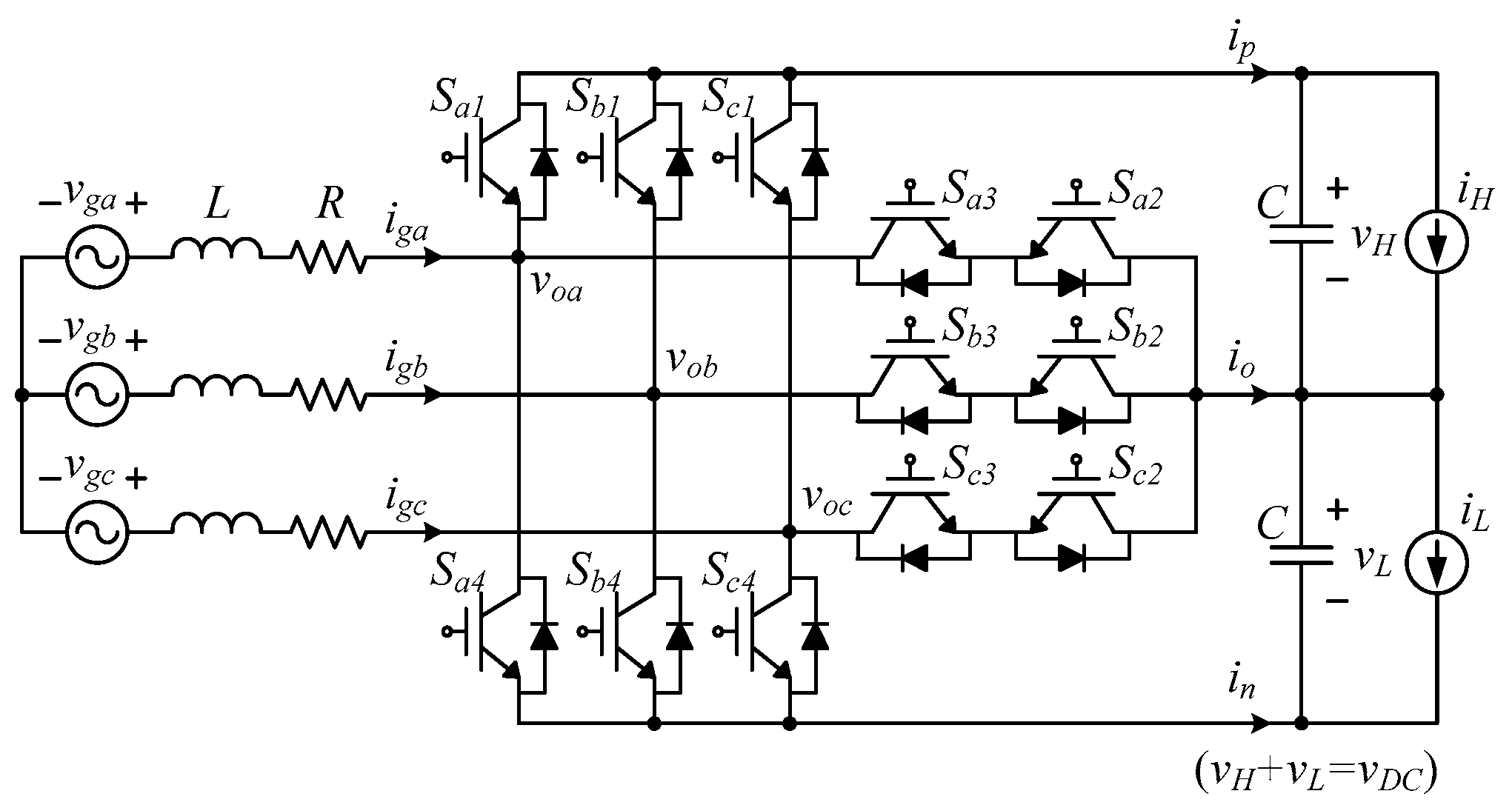
Figure 1. T-type three-level PWM converter system.
Energies 13 01324 g001
Figure 2. Phasor diagram of T-type three-level PWM converter operation.
Energies 13 01324 g002
Figure 3. Theoretical operational waveforms.
Energies 13 01324 g003
Figure 4. The exemplary O state duration time in sector I-A of Figure 3.
Energies 13 01324 g004
Figure 5. Control block diagram of the T-type three-level PWM converter system.
Energies 13 01324 g005
Figure 6. The block diagram for the neutral point voltage control loop.
Energies 13 01324 g006
Figure 7. Simulation waveforms at unity power factor operation under unbalanced load conditions. (a) Average model (da, db, dc: original duties; doa, dob, doc: final duties considering the SVM and offset voltage; iga, igb, igc: grid currents; io: neutral point current). (b) Switching model (vga, vgb, vgc: grid voltages; iga, igb, igc: grid currents; vH, vL: DC-link voltage; io: neutral point current; io_Ts: averaged neutral point current in every sampling period).
Energies 13 01324 g007
Figure 8. Simulation waveforms at non-unity power factor operation under unbalanced load conditions. (a) Average model (da, db, dc: original duties; doa, dob, doc: final duties considering the SVM and offset voltage; iga, igb, igc: grid currents; io: neutral point current). (b) Switching model (vga, vgb, vgc: grid voltages; iga, igb, igc: grid currents; vH, vL: DC-link voltage; io: neutral point current; io_Ts: averaged neutral point current in every sampling period).
Energies 13 01324 g008
Figure 9. Photograph of the experimental prototype.
Energies 13 01324 g009
Figure 10. Experimental waveforms at unity power factor operation under unbalanced load conditions.
Energies 13 01324 g010
Table 1. Neutral Point Current Expression.
SectorNeutral Point Current
IA i o = α 1 + m · I p ( β 2 + ( 3 / 4 ) · cos ϕ 2 ( 3 / 4 ) · s i n ϕ 2 )
B i o = α 1 + m · I p ( β 3 + ( 3 / 4 ) · cos ϕ 2 + ( 3 / 4 ) · s i n ϕ 2 )
IIA i o = α 3 + m · I p ( β 1 ( 3 / 4 ) · cos ϕ 2 + ( 3 / 4 ) · s i n ϕ 2 )
B i o = α 3 + m · I p ( β 2 ( 3 / 4 ) · cos ϕ 2 ( 3 / 4 ) · s i n ϕ 2 )
IIIA i o = α 2 + m · I p ( β 3 + ( 3 / 4 ) · cos ϕ 2 ( 3 / 4 ) · s i n ϕ 2 )
B i o = α 2 + m · I p ( β 1 + ( 3 / 4 ) · cos ϕ 2 + ( 3 / 4 ) · s i n ϕ 2 )
IVA i o = α 1 + m · I p ( β 2 ( 3 / 4 ) · cos ϕ 2 + ( 3 / 4 ) · s i n ϕ 2 )
B i o = α 1 + m · I p ( β 3 ( 3 / 4 ) · cos ϕ 2 ( 3 / 4 ) · s i n ϕ 2 )
VA i o = α 3 + m · I p ( β 1 + ( 3 / 4 ) · cos ϕ 2 ( 3 / 4 ) · s i n ϕ 2 )
B i o = α 3 + m · I p ( β 2 + ( 3 / 4 ) · cos ϕ 2 + ( 3 / 4 ) · s i n ϕ 2 )
VIA i o = α 2 + m · I p ( β 3 ( 3 / 4 ) · cos ϕ 2 + ( 3 / 4 ) · s i n ϕ 2 )
B i o = α 2 + m · I p ( β 1 ( 3 / 4 ) · cos ϕ 2 ( 3 / 4 ) · s i n ϕ 2 )
Table 2. System Parameters.
Output power (Po)3.2 kW
DC-link voltage (vH, vL)200 V
Grid line-to-line voltage220 Vrms
Filter inductance (L)3 mH
Equivalent series resistance (R)0.1 Ω
Output capacitance (C)1680 uF
Switching frequency (fs)10 kHz