Article

Membrane Capacitive Deionization for Cooling Water Intake Reduction in Thermal Power Plants: Lab to Pilot Scale Evaluation

1
VITO nv, Boeretang 200, 2400 Mol, Belgium
2
ENGIE Lab, Rodestraat 125, 1630 Linkebeek, Belgium
*
Author to whom correspondence should be addressed.
Energies 2020, 13(6), 1305; https://doi.org/10.3390/en13061305
Submission received: 13 February 2020 / Revised: 5 March 2020 / Accepted: 6 March 2020 / Published: 11 March 2020
(This article belongs to the Special Issue Energy-Water Nexus)

Abstract

:
Cooling of thermal power stations requires large amounts of surface water and contributes to the increasing pressure on water resources. Water use efficiency of recirculating cooling towers (CT) is often kept low to prevent scaling. Partial desalination of CT feed water with membrane capacitive deionization (MDCI) can improve water quality but also results in additional water loss. A response surface methodology is presented in which optimal process conditions of the MCDI-CT system are determined in view of water use efficiency and cost. Maximal water use efficiency at minimal cost is found for high adsorption current (2.5 A) and short adsorption time (900 s). Estimated cost for MCDI to realize maximal MCDI-CT water use efficiency is relatively high (2.0–3.1 € m−3evap), which limits applicability to plants facing high intake water costs or water uptake limitations. MCDI-CT pilot tests show that water use efficiency strongly depends on CT operational pH. To allow comparison among pilot test runs, simulation software is used to recalculate CaCO3 scaling and acid dosage for equal operational pH. Comparison at equal pH shows that MCDI technology allows a clear reduction of CT water consumption (74%–80%) and acid dosage (63%–80%) at pH 8.5.

Graphical Abstract

1. Introduction

Energy production accounts for 10% of freshwater withdrawal globally [1]. However, a much larger fraction of total freshwater withdrawal is used for energy production in industrialized countries, e.g., USA (50%), Western Europe (50%) and China (86%) [1,2]. The majority of withdrawal is used for cooling in thermal energy production [3]. The consumption of cooling water in thermal power plants depends highly of geographical location, cooling and fuel type [4] and is generally high for nuclear, coal and gas fired plants. The use of large amounts of fresh water for power production contributes to the increasing pressure on local water resources [2,3,4,5]. Reducing the freshwater withdrawal for cooling is expected to result in a substantial reduction in the water footprint of the energy sector. In general, four types of cooling systems can be employed for electricity generation including once-trough, recirculating, dry and hybrid cooling [5]. Dry cooling relies on air as the coolant medium eliminating water withdrawal and consumption totally. The capital cost of dry cooling is approximately ten times higher than that of once-through cooling [5]; as a result, its use is generally restricted to cases where insufficient make up water supply is available. Once-trough cooling using fresh water is less favored due to its large thermal emission to the surface water body; and [6] the number of power plants utilizing wet (evaporative) cooling systems with an open recirculating cooling tower has therefore rapidly increased [7]. Recirculating cooling towers operate in a feed and bleed mode. Circulating water is evaporated to reject heat while fresh feed water is continuously added, and a fraction of the circulating water is discharged as blowdown. Water withdrawal required for cooling depends on the maximum salt concentration that can be maintained in the recirculation water, which is typically limited by operational aspects such as mineral precipitation and scaling [5]. Scaling involves the precipitation of partially water-soluble salts such as calcium carbonate (CaCO3), which is driven by increasing calcium concentration, pH or alkalinity due to evaporation. The CaCO3 hardness of surface water used for cooling depends highly on the geohydrology of the aquifer and can range from soft (<60 mg/L CaCO3) to very hard (>180 mg/L CaCO3). Previously explored strategies to improve water efficiency of wet cooling towers include feed pretreatment [8,9], use of alternative feed sources [10], circulation water conditioning and acidification [11] and blowdown recuperation [12,13,14].
Feed pretreatment can be achieved with several processes or process trains including conventional clarification, ion exchange and membrane filtration. Membrane based water treatment technologies have essential advantages over ion exchange in terms of environmental indicators but produce more effluent [8]. Membrane capacitive deionization (MCDI) is an emerging electromembrane process that makes use of electrostatic adsorption to remove ions from a feed stream. An MCDI cell consists of two carbon electrodes covered with ion exchange membranes and separated by a flow channel. During purification, a feed stream is applied to the flow channel, and an electric potential is applied to the electrodes. Ions of opposite charge are attracted and electrosorbed in electrical double layers in the anode and cathode, respectively, and thus removed from the feed stream. Accumulation of ionic charge on the electrode increasingly compensates the applied potential until electrode regeneration is required. During regeneration, the electric polarity is reversed to cause desorption of adsorbed ions. This cycle of purification and regeneration produces two streams, desalinated water and brine. Ion exchange membranes are placed in front of the electrodes in MCDI to prevent that during regeneration ions of opposite charge are attracted from the bulk fluid. This would result in incomplete regeneration leading to a reduced electrode adsorption capacity and longer regeneration times during the next purification step [15]. Application of MCDI for surface or brackish water desalination is characterized by low energy consumption, high water recovery and low fouling propensity [16] in comparison to pressure driven processes. A recent pilot study from Tan et al. [17], using a similar MCDI module as used in this work, showed the possibility of further reducing energy consumption by 30% to 40% using an innovative energy recovery system. MCDI is expected to be less prone to fouling and scaling than other membrane-based desalination technologies [18]. The membranes in MCDI protect the carbon electrodes [19] and due to frequent electrode reversal, build-up of fouling is prevented in a similar way to electrodialysis reversal [15]. MCDI is therefore a potentially highly interesting technology for cooling tower feed pretreatment. MCDI is currently not yet widely applied on a large scale but is considered a viable alternative for partial demineralization of low salinity streams [15,20,21]. A limited number of MCDI pilot studies has been published [15]. Dorji and coworkers performed a pilot scale test with MCDI as alternative for 2nd stage RO in seawater desalination. The results showed that MCDI can effectively remove bromide and dissolved salt at lower energy consumption (0.15 kWh m−3) compared with second stage RO (0.35 kWh m−3) at high water recovery [22]. Van Limpt and Van der Wal [9] performed an MCDI pilot study in which MCDI is used to desalinate tap water as feed for an industrial cooling tower (500 kW) and a residential cooling unit (4500 kW). Chemical savings of up to 85% and water savings up to 28% at low energy consumption (0.11–0.23 kWh m−3 produced water) were achieved in this study. MCDI water recovery was limited to 80% to prevent calcium carbonate precipitation. However, a preferential uptake of chloride and calcium (20%) was found resulting in a lower risk of CaCO3 scaling. The authors concluded that the energy consumption was similar to what is expected from reverse osmosis (RO). A similar range of energy consumption for RO is mentioned by Qin et al. [23] who developed a mathematical model to compare the energetic performance of MCDI and brackish water RO (BWRO). They concluded BWRO to be significantly more energy efficient than MCDI, at high salt rejections and moderate to high water salinities.
The potential of MCDI for the reduction of cooling water intake in thermal power plants is studied in this paper. An experiments-based approach is used to evaluate the combined performance of MCDI and a cooling tower. Lab scale experimental data is used in a response surface methodology to determine the optimal working conditions of the coupled MCDI-CT system in view of water use efficiency and cost. The resulting optima are reevaluated for real CT feed water samples in MCDI lab tests and subsequently in an MCDI-CT pilot case study.

2. Materials and Methods

2.1. CT Water Efficiency

Recirculating cooling towers operate in a feed and bleed mode. Circulating water is evaporated to reject heat while fresh feed water is continuously added, and a fraction of the circulating water is discharged as blowdown. The water regime of a cooling tower is conventionally expressed in terms of cycles of concentration (COC). COC measures the degree to which the solid impurities in the makeup water are concentrated in the recirculating water of an evaporative system due to evaporation of water. COC is defined (Equation (1)) as the ratio between chloride concentration (chemical COC) in the circulation water and make-up water or in terms of flowrate (physical COC) of make-up (Qmakeup) and evaporate (Qevap).
C O C = [ C l ] c i r c u l a t i o n [ C l ] m a k e u p   Q m a k e u p Q m a k e u p Q e v a p = 1 1 Q e v a p / Q m a k e u p
A more conventional parameter for a system’s water use is water use efficiency or utilization (U), defined as the ratio of effectively used (evaporated) water flow over feed water flow (Equation (2)).
U = Q e v a p Q i n
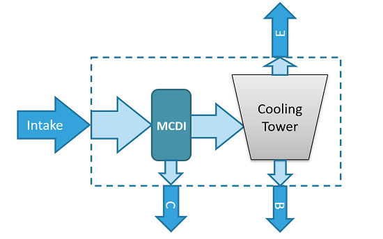
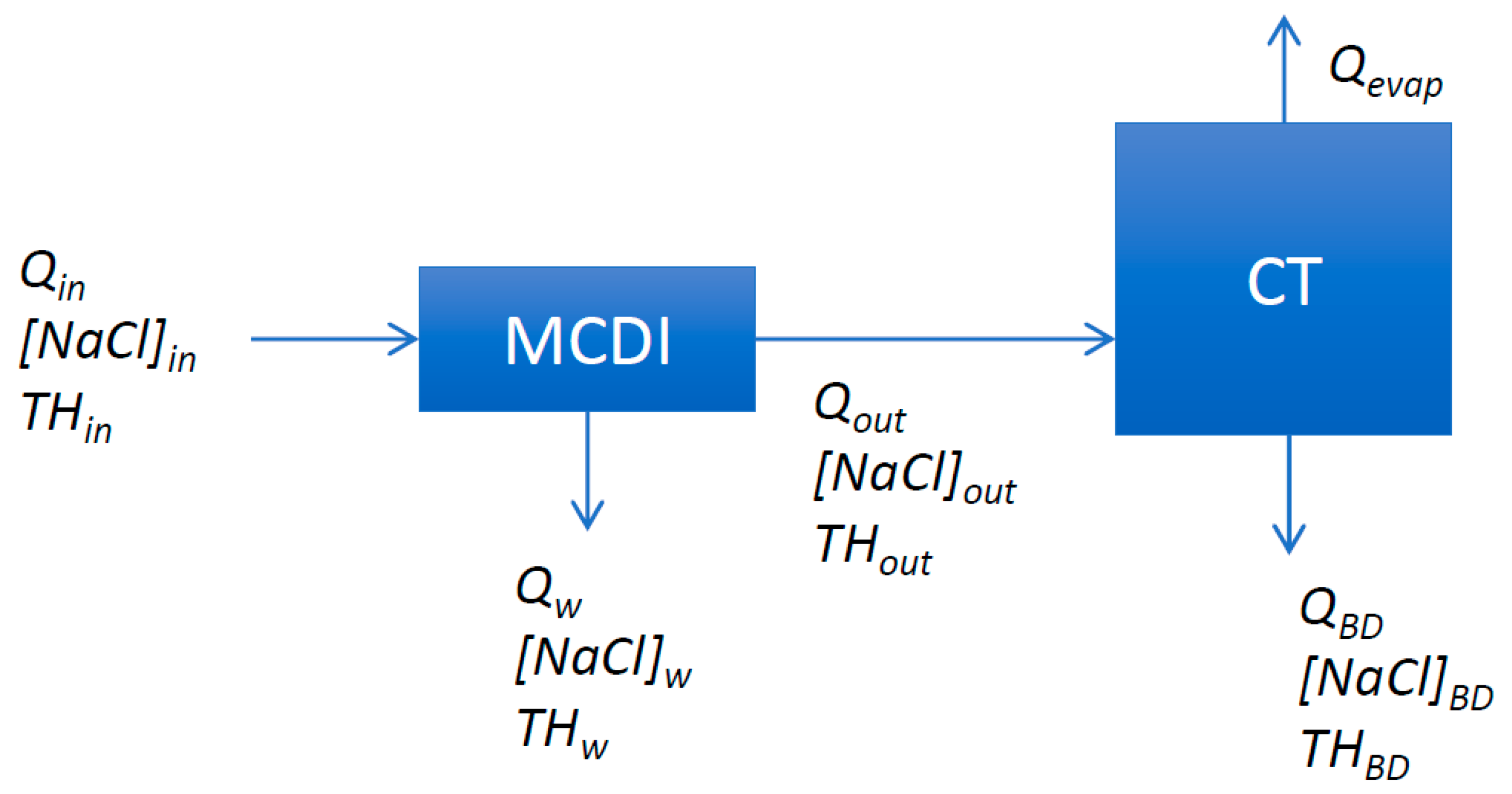
COC is the reciprocal of (1 − U) and therefore a non-linear and less appropriate measure of CT water consumption (Equation (1)). For the coupled MCDI-CT system (Figure 1) it is therefore preferred to use U as a measure for water consumption (Equation (2)).
For the MCDI-CT system, U is found as the ratio (Equation (2)) of evaporate flow and MCDI intake water flow (Qin). The maximal achievable utilization (Umax), i.e., the maximal fraction of intake water flow that can be used for evaporation, is of specific interest when comparing the efficiency of MCDI-CT under various settings and feed water types. Umax is limited by both MCDI water recovery and the maximal CaCO3 concentration that can be achieved in the cooling tower not causing scaling (Equation (3)). For practical use, this can also be expressed in terms of MCDI process characteristics.
U m a x = Q e v a p , m a x Q i n = W R ( 1 T H o u t T H B D ,   m a x )
where Umax is determined by maximal achievable evaporation flow (Qevap,max), MCDI intake flow (Qin), MCDI water recovery (WR), hardness of the MCDI treated water (THout) and maximal allowable hardness in the CT (THBD,max) limited by the maximal solubility of CaCO3. Scaling (by CaCO3) is applied here as single limiting concentration factor for CTs. Several alternative limiting conditions for CT water usage can obviously be envisaged including discharge limitations, material technical limitations (e.g., corrosion) and non CaCO3 related scaling/fouling. These additional limitations could be implemented however following a similar approach.

2.2. MCDI Lab Tests: Setup

The lab-scale setup consists of an Enpar Inc. (Guelph, ON, Canada) lab-scale MCDI cell (0.7 m2 electrode surface) coupled to a Voltea MCDI circulation loop (Sassenheim, the Netherlands). The system is equipped with a DC power supply, pump, conductivity probe, valves, flow meter and a laptop with LabView-based control and data logging software. During operation, the MCDI system passes through cycles of purification and regeneration. During the purification step, charge builds up in the electrodes as ions are adsorbed from the water. Regeneration is achieved by reversing the polarity over the MCDI cell. All experiments are carried out under fixed flow rate, adsorption current and adsorption time. At the start of each experiment, the MCDI-module is shorted and rinsed with feed water for at least 30 min (at adsorption flowrate) until outlet conductivity equals feed conductivity. In each experiment at least 10 cycles (adsorption-desorption) are completed in flow-through mode (no recycle). Desorption is performed at constant voltage (−1.2 V) or at maximal desorption current (110 A) if −1.2 V is not reached; desorption flow rate is equal to adsorption flow rate and constant; maximal current is applied during desorption; the required desorption time is derived from the charge balance. Feed water is filtered (Pall profile II filter cartridge, 5 µm) prior to testing. During experiments pH, EC (µS cm−1), ΔV (V), Q (mL min−1) and I (A) are continuously monitored. Samples are taken from the influent, purified and waste streams during the last 3 cycles and analyzed for Cl (discrete analysis system and spectrophotometric detection), Na and Ca (ICP-OES).

2.3. MCDI Lab Tests: Experimental Design

MCDI parameter screening is performed on synthetic cooling water following a design of experiments (DOE) approach. Synthetic cooling water is prepared from demineralized water, pro analysis grade NaCl (Merck, Darmstadt, Germany) and CaCl2 (≥94% Merck). The chosen experimental design [24] is a half fractional central composite design (CCD) with 5 factors at 2 levels, i.e., a 2(5−1) design, and star points (α = 1.719, 30 runs, 3 center points). This type of design consists of a fractional factorial design with center points and is augmented with a group of ‘star points’ to allow estimation of curvature. The star points are at distance alpha (α) from the center and represent extremes for the low and high settings for all factors. The design is of resolution V, indicating no main effect or two-factor interaction is aliased with any other main effect or two-factor interaction, but two-factor interactions are aliased with three-factor interactions. α is computed for orthogonality using Dell Inc. (2015) Statistica software (data analysis software system, version 12). The design contains 5 factors of which three are MCDI operational factors (adsorption phase time (tads), adsorption current (Iads), adsorption phase flowrate (Qads)) and 2 factors are related to feed water composition ([NaCl]in, feed water hardness (THin)). Factor ranges are selected based on previous experience and real cooling tower feed water qualities (Table 1).
Primary (directly measured) response variables are product water composition ([NaCl]out, THout) and MCDI water recovery (WR). Secondary (calculated) response variables are specific energy use (E, kWh m−3in), estimated cost (Cost, € m−3in) both expressed relative to the feed water flow and selectivity (S, -). Cost estimation is based on the experimental data and standard cost data (unit cell cost: 150 € m−2 electrode, E-cost: 0.1 € kWh−1, cell lifetime: 2 years, installation depreciation: 10 year at 4% rate of investment, yearly maintenance cost: 5% of investment). Where required electrode surface (Ael) is determined from lab cell electrode surface (Acel) and flow (Equation (4)).
A e l = A c e l Q i n
Selectivity [25] is calculated as the ratio of the molar ratio of hardness of the MCDI feed water and the MCDI product water (Equation (5)).
S = M CaCO 3     T H i n     M CaCO 3     T H i n +   M NaCl     [ NaCl ] i n M CaCO 3     T H o u t   ( M )   M CaCO 3     T H o u t   +   M NaCl     [ NaCl ] o u t
where M i (g mol−1) indicates the molar masses of CaCO3 and NaCl, respectively. Least-squares multiple regression analysis (Anova) is applied to determine the functional relationship between factors and responses using following polynomial equation (Equation (6)):
Y = b 0 + i b i X i + i j b i j X i X j + ε
where Y represents a response variable, b regression coefficients, X factors, ε experimental error and i, j running variables. The significance of the generated response surface (RS) equations and model terms are evaluated from Anova table (α > 0.05), adjusted coefficient of performance (R2adj.), residuals distribution and Pareto analysis. Insignificant terms are removed in a stepwise model reduction procedure until a fully reduced model is obtained [26]. Experimental design and statistical analysis are performed with Dell Inc. (2015) Statistica (data analysis software system), visualization with Matlab 2016 version 12 (The MathWorks, Natick, MA, USA) and data preprocessing with MS office (Microsoft).

2.4. CT Feed Water

Cooling tower feed water samples are collected from 3 existing thermal power plant locations (Brussels-Charleroi (BC) Canal, Belgium; Gent-Terneuzen (GT) Canal, Belgium; Eume river, Spain) and treated municipal sewage water (STP effluent; Mol, Belgium). MCDI tests are performed with real cooling water samples to compare the effect of different feed water types on MCDI-CT process parameters (E, S, Umax and Cost). Following process settings are used: (tads, Iads) = (900 s, 2.5 A) and (tads, Iads) = (2000 s, 1 A), for each setting two flowrates are selected (60 and 120 mL min−1).

2.5. MCDI-CT Pilot

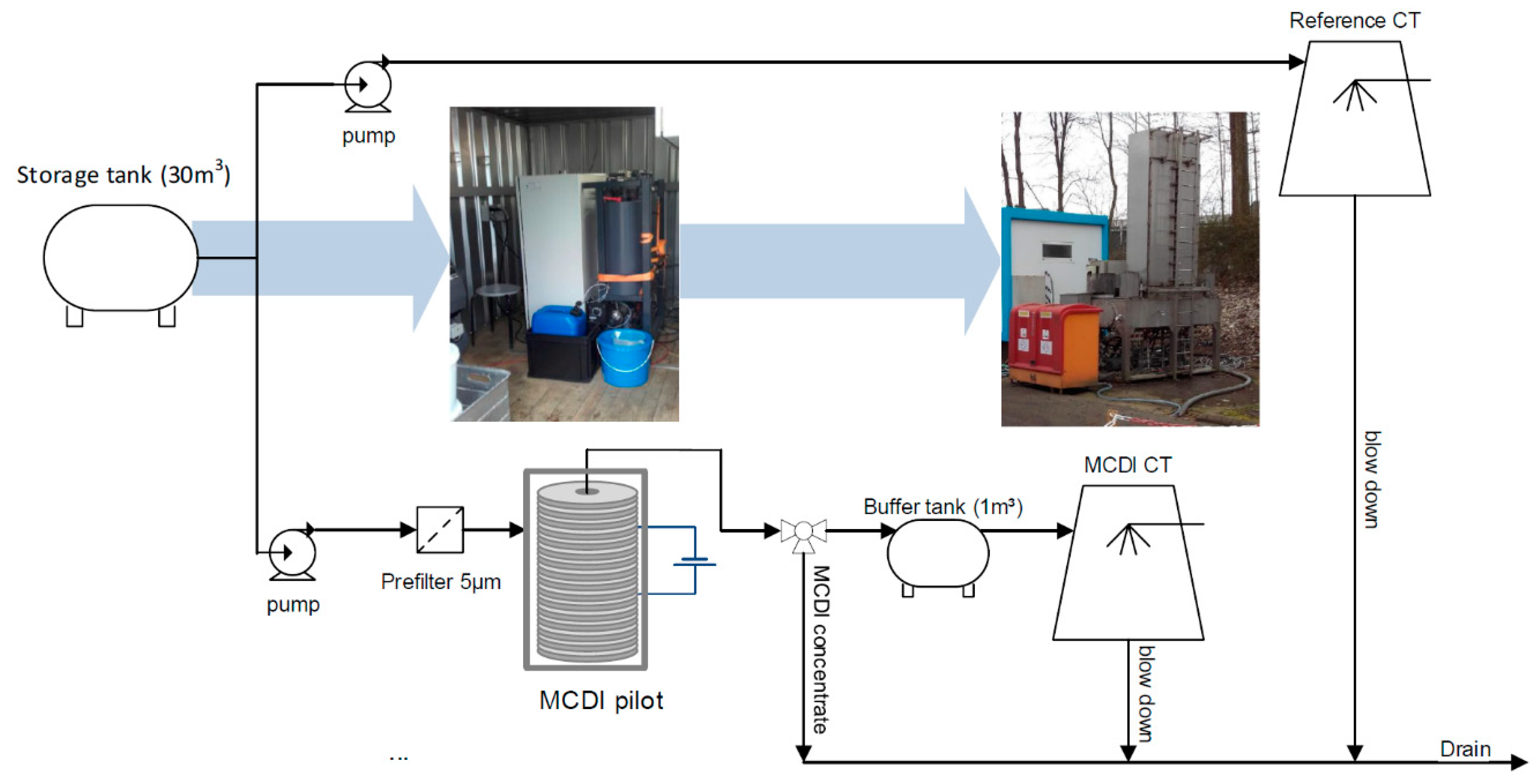
The MCDI-CT pilot installation consists of a 30 m3 feed tank, MCDI container and a mobile cooling tower unit (Merades). The MCDI 10-foot container holds a prefiltration device (5 µm bag filter, Filtermat) coupled to a Voltea CAP-DI IS2 MCDI unit with a capacity of 0.2–1.8 m3 h−1. The pilot is fully automated (Siemens PLC) and remotely controllable, Selenium webdriver with Python is used for data collection. 0.1 M NaOH and 0.1 M citric acid solutions are used for cleaning in place (CIP). Merades consists of two parallel and independent cooling tower loops simulating semi-open cooling circuits. Each circuit consists of a cooling tower basin, circulation pump and a 12 m length condenser pipe. Water is pumped from the cooling water basin through the condenser where water temperature is slowly increased, condenser outlet temperature is controlled, and is subsequently sent to the cooling tower where it is cooled before flowing down back into the cooling tower basin. The cooling tower is equipped with a nozzle to spray the water through a fill. The temperature in the cooling tower basin is regulated by varying the forced air flow (ventilator) in the cooling tower. The COC of the cooling circuit is regulated by a blowdown pump. Merades is equipped with automated injection system and continuous inline monitoring. Make-up and circulation water are monitored for pH and EC (continuously), hardness (TAC and THCa) and chlorides (hourly), LPR corrosion measurement (3 times/week), free and total ATP and total viable count (weekly).
The pilot installation was operated for 6 test runs during a 12-week test period (May–July 2018, Linkebeek Belgium). Feed water is abstracted from Brussels-Charleroi Canal and transported to the pilot location (Engie Laborelec, Linkebeek, Belgium) on ~weekly basis. In each test, Merades loop 1 is fed with untreated Canal water (reference) while loop 2 is supplied with MCDI treated water. COC of both Merades loops is gradually increased until scaling occurs to determine the maximal achievable COC. Condenser inlet pH is maintained constant at pH 8.0 (H2SO4) in each test. Scaling onset is determined from circulating water [Ca2+]/[Cl] ratio. When minimal blowdown flowrate is reached (4 × 10⁻³ m3 h−1, COC 4 to 5) without scaling occurring, pH is gradually increased to induce scaling. Fixed operational CT parameters include condenser outlet T (37 °C), ∆T in condenser (10 °C), CT water T (27 °C), water spread in condenser pipes 1.46 m s−1, circulation flow rate 1.9 m3 h−1, packing spraying flow rate 8 m3 m−2 h−1, hydraulic halftime 0.25 h. Stainless-steel condenser pipe and film fill (height 1.5 m) are used. Following each test, the cooling water circuits are cleaned (concentrated HNO3, pH < 2.0 for 2 h minimum). MCDI CIP is performed following each test and intermittently when required. After cleaning the system and modules are thoroughly rinsed with demineralized water.

3. Results and Discussion

3.1. MCDI Response Surface

Measured response variables and calculated response variables are determined from MCDI lab tests (Table 2).
The primary response data include [NaCl]out, THout and WR. Comparison of [NaCl]out and [NaCl]in shows that feed water NaCl concentration is effectively reduced during MCDI tests. A maximal reduction of 91% in [NaCl] is found (run 20) while median removal equals only 16%. This indicates that overall removal of [NaCl] is relatively low, which is expected when aiming for partial desalination. A similar trend is found for TH, maximal removal amounts to 88% while median removal equals 23%. Water recovery is generally high for MCDI tests (67% min. to 85% med. to 95% max.) This is desired as MCDI WR is expected to largely affect overall water use efficiency when MCDI is used in combination with a CT. Secondary response variables include specific energy use (kWh m−3in), estimated cost (€ m−3in) and selectivity (-). The median specific energy use of the MCDI system amounts to 0.18 kWh m−3, which is well within the expected range [9,20]. Maximal E (0.58 kWh m−3) is found for test run 20 in which 90% reduction in [NaCl] was obtained. Cost estimates range from 0.59 € m−3in minimum over 0.98 € m−3in median to 2.95 € m−3in maximum. Cost estimates in literature are scarce and range from low, 0.11 $ m−3 for CDI (no membranes) on low salinity feed of ≤2000 ppm assuming a 15-year module depreciation [27], to high, 11.7 € ton−1 for a 3 kg m−3 [Na+] biomass hydrolysate [28]. It needs to be mentioned that the purpose of cost estimation is to distinguish between the economics of different process settings rather than to mirror the exact cost of the MCDI process. Selectivity is calculated for the different runs and S is found to vary between 0.8 minimum and 1.45 maximum with 1.08 as median. Following data acquisition, least-squares multiple regression analysis and a subsequent model reduction procedure are applied resulting in a set of regression equations relating response variables to relevant factors and combinations thereof (Table 3).
The equations for the primary response variables [NaCl]out and THout have a good fit (R2adj., R2 = 0.99 and 0.95), while that for WR is less good (R2adj. = 0.83). Post-hoc testing of residuals shows that the assumption of normality is satisfied (Shapiro–Wilk’s (SW) W test: [NaCl]out, W = 0.96, p = 0.40; THout, W = 0.98, p = 0.76; WR, W = 0.95, p = 0.17). The effect of different factors on response variables is quantified by the pareto order of their standardized effects (Table 3). It can be seen that [NaCl]out depends largely on the [NaCl]in. Besides this effect, Qads, Iads and tads have a smaller but relevant influence on desalination. Low [NaCl]out occurs for intermediate tads, high Iads and low Qads. From factor signs, it can be seen that [NaCl]out is lowest at low flow rates. This is in accordance with previous findings [30], ion removal rate increases with increasing flowrate, but the effect of shorter contact time due to increased flow rate is larger. THout depends largely on THin and is also lowest at intermediate tads, high Iads and low Qads. Trends for THout are highly similar to those for [NaCl]out. In addition, less hardness is removed from brackish water compared to sweet water, since THout depends also on [NaCl]in. Maximal WR is achieved at low Iads and short tads, which conflicts with the desired parameter settings required for low THout and [NaCl]out. For the secondary response variables, only the reduced equation for Cost has a good fit (R2adj. = 0.95). The equation (Table 3) indicates that Cost is depending of Qads and Q2ads only. Flowrate is directly related to required electrode surface, which confirms the notion that MCDI cost is largely determined by equipment cost [23]. Residuals analysis shows a systematic underprediction of cost at low flowrate and overprediction at high flowrate causing the normality assumption not to be satisfied (SW, W = 0.77, p < 0.001). A power law of Q and Cost is fit and used instead for further evaluation (Cost = 146, Qads−0.997, R2 = 0.99). The model equation for E has a less good fit (R2adj. = 0.82) and residuals normality was not satisfied (SW, W = 0.91, p = 0.013). The model equation for S consists of an intercept only. This is indicative of a small but significant selectivity for Ca2+ removal ( S ¯ = 1.11; t (4.9); p < 0.001). The equations for S and E are not further used in the analysis of the combined MCDI-CT system.

3.2. MCDI-CT Process Evaluation

3.2.1. Water Use Efficiency

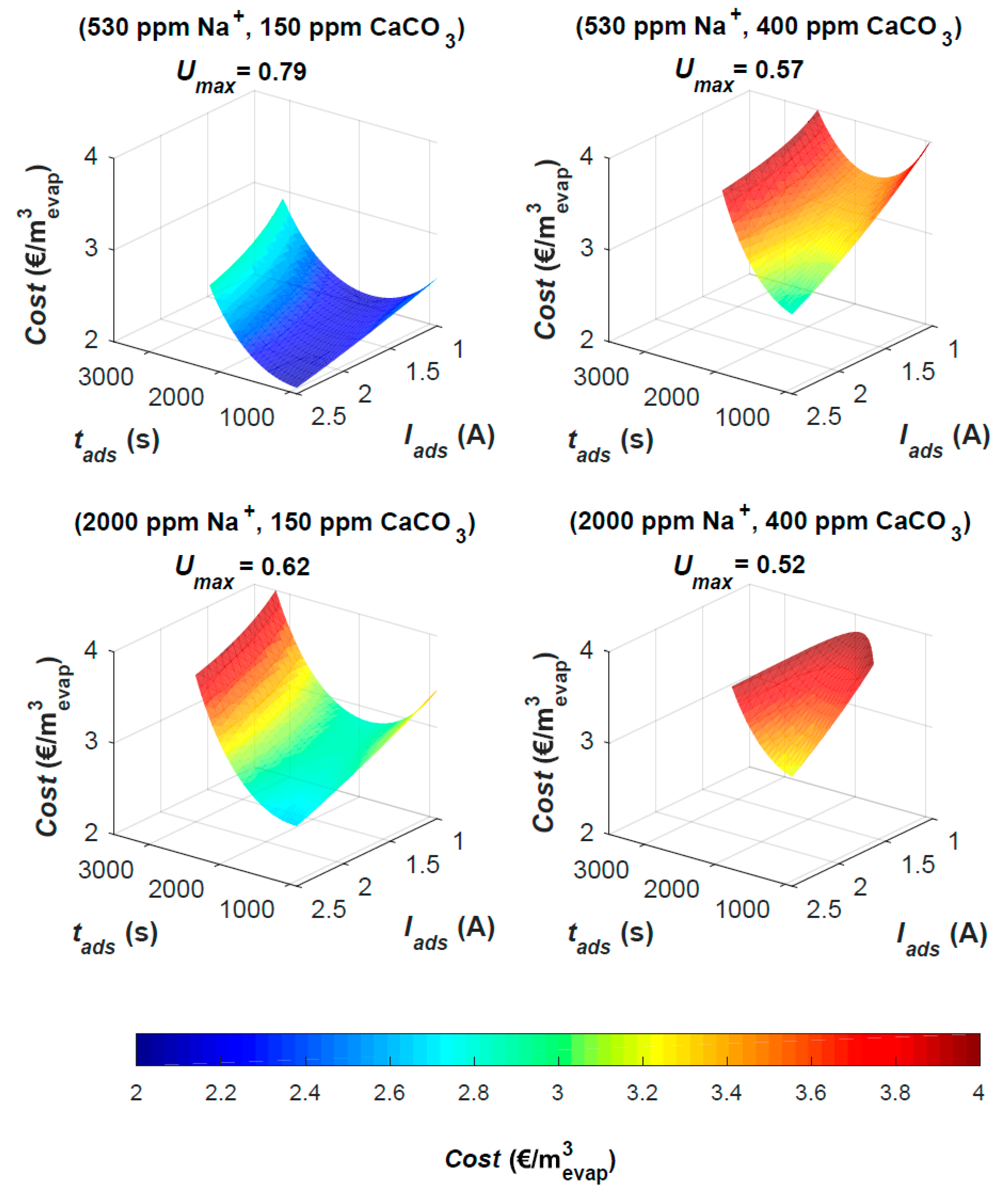
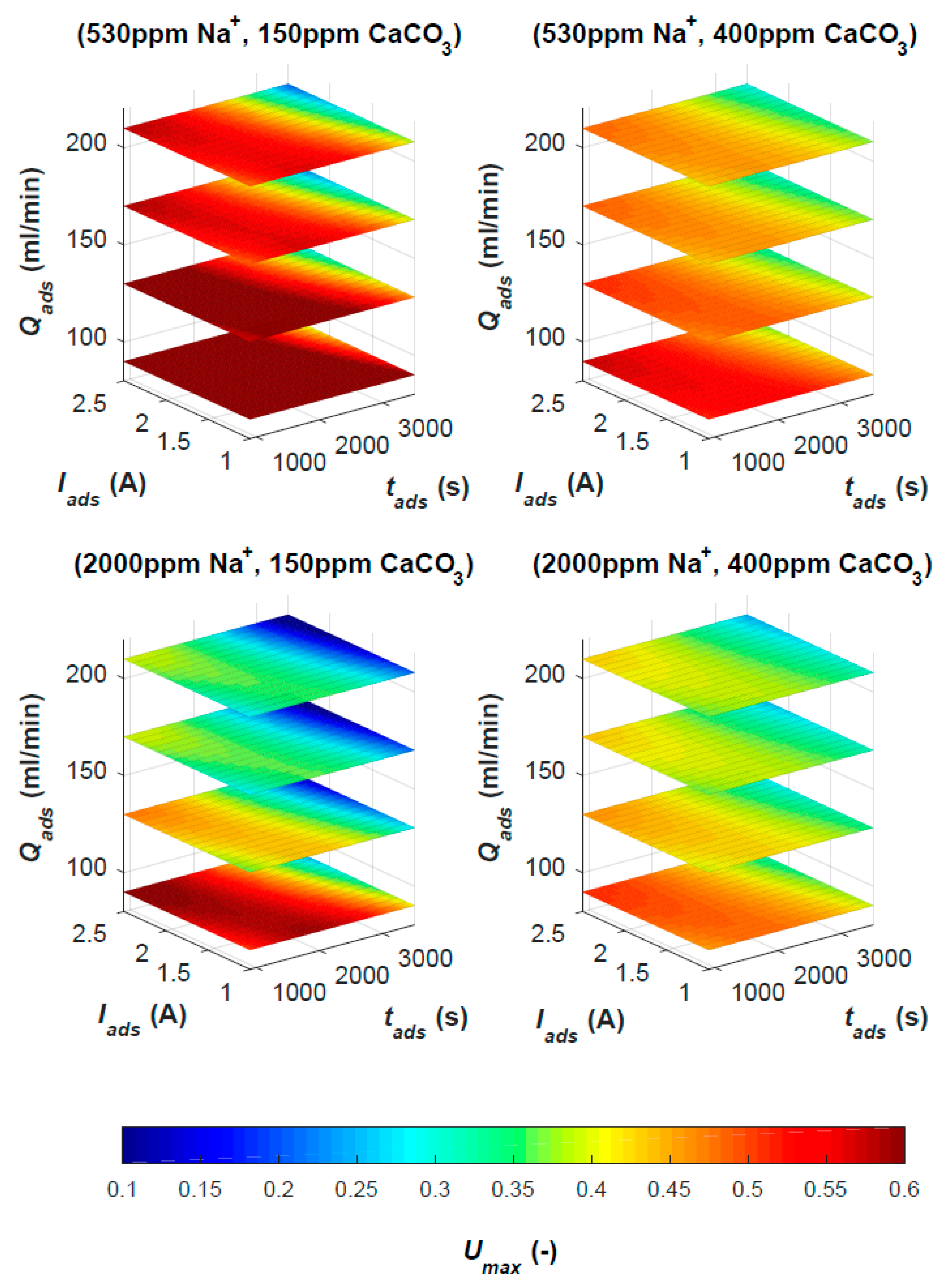
MCDI is studied as CT pretreatment in order to maximize water use efficiency. The MCDI process settings that result in the largest water use efficiency are therefore of interest and are determined from the MCDI response surface model (RSM). More specifically Umax (Equation (3)) is determined from WR and THout model equations as function of process settings (Qads, Iads and tads) and feed water types. Feed water quality is reduced to four distinct feed water types (sweet/soft, sweet/hard, brackish/soft, brackish/hard) to allow to visualize Umax. Hardness limit (THBDmax; Equation (3)) is set to TH 225 ppm CaCO3 for soft water and TH 600 ppm CaCO3 for hard water. This accords to a maximal COC of 1.5 or a Umax of 0.33 for a CT without pre-treatment. Values are based on the operational conditions of existing Belgian power plants located at Brussels-Charleroi Canal and Ghent-Terneuzen Canal. Evaluation of the resulting volume plots (Figure 2) reveals that the highest Umax can be obtained with MCDI treated sweet/soft water. Optimal Umax for sweet/soft water type (Umax = 0.79) is the highest achievable value of Umax in the evaluated parameter space (tads = 900 s; Iads = 2.5 A; Qads = 90 mL min−1). Application of MCDI on sweet/soft water results in the lowest THout resulting in higher achievable water use efficiency when compared to high salinity or high hardness water types.
Lowest Umax values are found for hard/brackish water with a lower optimal Umax = 0.52 realized at low Qads, high Iads and intermediate tads. MCDI on intermediate water types results in intermediate optimal Umax (0.57 hard/sweet and 0.62 soft/brakish). An overall trend is observed for Umax as function of the studied operational parameters and different feed water types. Within a specific feed water type, flow rate is found to have the largest effect (inverse) on Umax (colour gradient varies strongest with Qads). Comparison amongst different feed water types shows that the dependency of Umax on flowrate is strongest for sweet water. For a given flowrate, a ridge type optimum is found stretching from high Iads and low tads to low Iads and intermediate tads.

3.2.2. Cost Estimate

Estimated cost is determined from energy consumption and required electrode surface (Equation (4)). Both parameters depend largely on flowrate. Increasing Qads causes specific energy consumption (SEC) and Ael to lower causing Cost to decrease. With increasing flowrate also Umax decreases which makes it of interest to optimize Umax and Cost in terms of Iads and tads. MCDI Cost is made relative to CT evaporate flow to allow comparison of cooling capacity for the 4 previously defined feed water types. Iso-surfaces are plotted which represent a single optimal Umax value as a function of cost (€ m−3evap.), Iads and tads (Figure 3).
Comparison of different feed water types shows a notable effect of THin on cost. Cost increases strongly with hardness and to a lesser extent with increasing [NaCl]in. For each feed water type, an optimum setting exists for tads and Iads resulting in lowest cost for a given Umax. These optima (Table 4) are found at high Iads combined with low tads or low Iads combined with intermediate tads similar to the previously described optima for Umax. For sweet/soft feed water, e.g., the optimum extends from low Iads (1 A) and optimal tads (~2000 s) up to high Iads (2.5 A) and an optimal tads (<1000 s). The existence of such optimum allows minimizing the cost by choosing optimal Iads and tads to achieve a given Umax. Since cost is determined by Qads, the objective could also be expressed as maximizing Qads to reach a specific Umax. Qads is a design parameter that largely depends on installation size for a given application. Alternative optima can be considered, e.g., maximizing Umax at fixed cost or minimizing footprint. Moreover, optimization of the product/waste cycle in MCDI can be of use to further maximize water recovery, since WR relates directly to Umax (Equation (2)).

3.3. MCDI on Real Feed Water

MCDI tests are performed on real CT feed water samples (BC Canal, GT Canal, Eumes River and STP effluent). Treated STP effluent is included as a possible alternative source of cooling water [31]. The selected feed water types have a distinct composition (Table 5). BC Canal water has a relatively low [Na+] and a medium to high TH ([Ca2+] = 125.7 ppm, [Mg2+] = 15 ppm). GT Canal feed water TH is highly similar to BC Canal ([Ca2+] = 114 ppm, [Mg2+] = 43 ppm) while being higher in [Na+] (300 ppm Na+). Eumes river feed water is very low in TH ([Ca2+] < 0.05 ppm, [Mg2+] < 10 ppm) with a relatively high [Na+] and high pH compared to the other water types. STP effluent has a low sodium concentration (22.2 ppm) and relative low TH ([Ca2+] = 23.9 ppm, [Mg2+] = 3.3 ppm). In addition, total organic carbon (TOC) is not considered specifically in this study but could contribute to membrane fouling. Indicative TOC values for the cooling water samples (Table 5) are 70 mg C/L (BC Canal), 4.4 mg C/L (Eumes river) and <15 mg C/L (STP effluent).
MCDI tests with real CT feed water are used to reevaluate the RSM model. Since both Eumes river and STP effluent water compositions are far outside the factor ranges of the RSM (Table 1) they are not used for comparison with model predictions. RSM ranges for THin and NaCl are based on the average composition of BC and GT Canal water types. Despite of seasonal variation the current samples (Table 5) have a similar composition (EC, [Ca2+]) when compared to the ranges used for RSM ([Ca2+]: 56–180 ppm, EC: 1.2 mS/cm–4.6 mS/cm), the current BC Canal water sample however has a relative low [Na+]in. For GT Canal and BC Canal feed water types, Umax, WR and THout are calculated from test results and from RSM equations (predicted value and 95% confidence interval, Statistica prediction and profiling tool) and compared (Figure 4).
Comparison results for GT Canal water shows that Umax and WR are well predicted by RSM. Prediction of parameter THout is less accurate and the inverse effect on Umax is notable (e.g., for 120-900-2.5). Average difference between RSM predicted and test results derived parameters is <5% for GT Canal water. Comparison of results for BC Canal shows a larger deviation; specifically, THout is overestimated by RSM. On average, RSM underestimates Umax by 20%, WR by 6% and overestimates THout by 89% for BC Canal water. Overestimation of THout is attributed to the relatively low [Na+]in in BC channel water (60.1 ppm) compared to the RSM factor range (Table 1) making the RSM model less predictive.
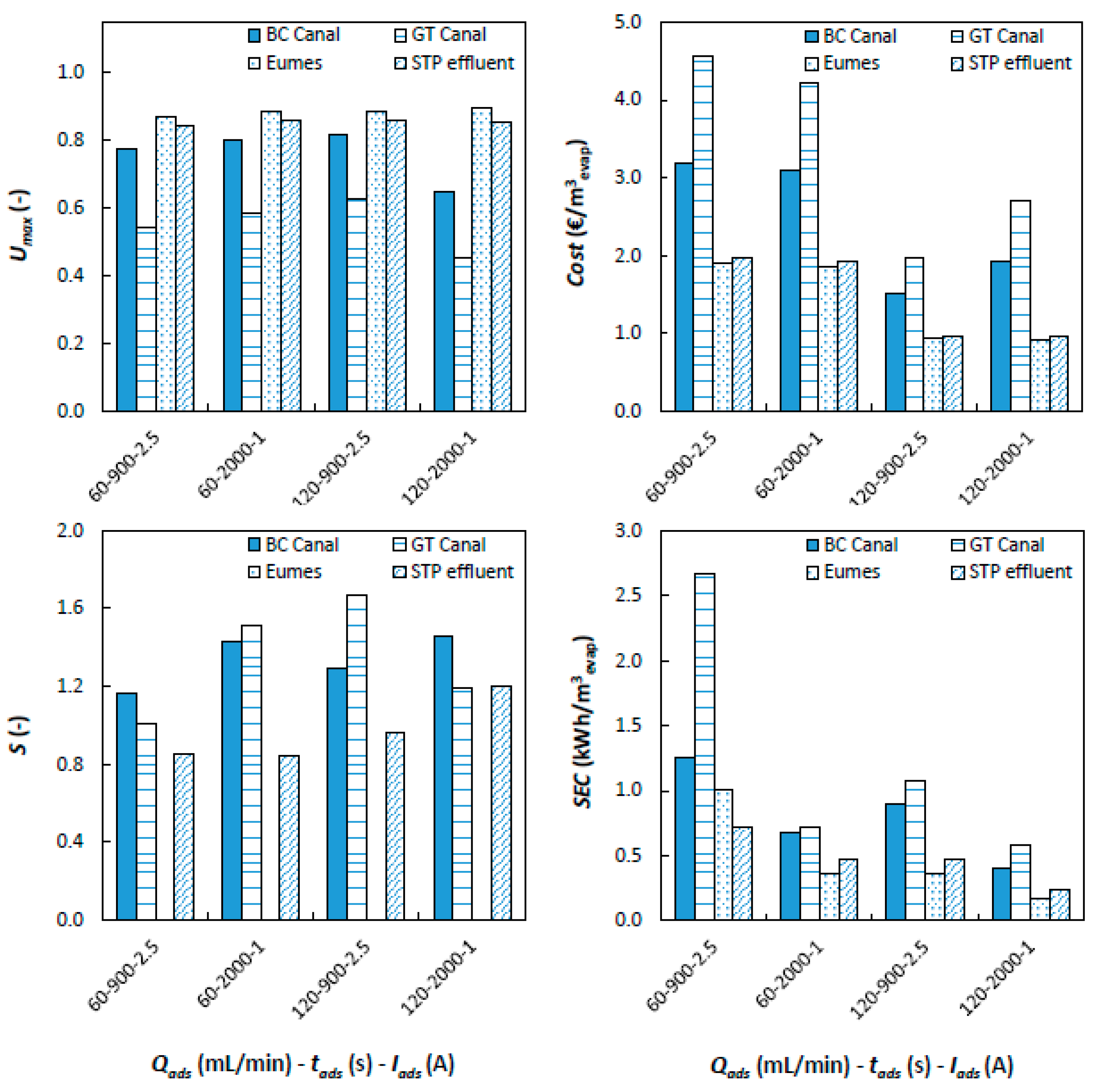
MCDI tests with real CT feed water are further used to evaluate the effect of feed water composition on MCDI-CT process parameters (SEC, selectivity, Umax and Cost). Desired properties of the MCDI process in relation to process efficiency are low cost, low energy consumption, high Umax and high selectivity (S) for bivalent ion removal (e.g., Ca2+, Mg2+). Process parameters are determined for the 4 selected water types and various MCDI process conditions and plotted for comparison (Figure 5).
Umax is found to be highest for Eumes river water followed by STP effluent, BC Canal and GT Canal feed water types. This expected as Umax is inversely correlated with feed water EC and TH following their effect on THout. Variation of Umax among process conditions is small, except for BC Canal and GT Canal feed water where ((tads, Iads):(2000 s, 1 A)) Umax is lower in comparison to other test conditions. This is also mirrored in Cost (€ m−3evap.), which is inversely correlated with flowrate and Umax and to a much lesser extent energy consumption (kWh m−3evap) as can be seen for BC and GT Canal feed water. Energy consumption (kWh m−3evap) is high for BC Canal and GT Canal water types when compared to STP effluent and Eumes feed water. Selective removal of bivalent ions (Ca2+ and Mg2+) is a desired MCDI feature. Selectivity is found to some extend for BC Canal water ( S ¯ = 1.35; Standard Deviation (SD) = 0.3; N = 4) and GT Canal water ( S ¯ = 1.34; SD = 0.13; N = 4). No selectivity was found for STP effluent ( S ¯ = 0.97; SD = 0.16; N = 4) while S could not be calculated for Eumes river water due to the lack of hardness ions. Preferential removal of bivalent ions is common in MCDI; it is observed in both synthetic feed mixtures [19,32] and real feed water [9]. This phenomenon is the result of diffusion kinetics and adsorption equilibria in MCDI and is attributed to the preferential storage of multivalent ions in ion exchange membranes [32,33]. Overall comparison shows that high flowrate (120 mL min−1) results in minimal Cost (€ m−3evap.) for all studied feed water types. Feed water with high THin (GT Canal, BC Canal) is preferably treated using short tads while applying high Iads. In addition, the gain in water use efficiency in relation to the base scenario where no pretreatment is in place needs to be considered. For BC Canal and GT Canal water utilization without treatment (Umax = 0.33) is relatively low making pretreatment of possible interest while for STP effluent (Umax = 0.76) and Eumes river (Umax = 0.99), utilization is already high, and therefore, pretreatment is not useful. Application of MCDI on BC Canal and GT Canal water types results in a relatively high estimated cost per m3 evaporate. This is partly due to the estimation procedure neglecting in part scale up effects. It generally indicates that the studied MCDI-CT scheme is currently only useful when CT feed water is costly or when legislative boundaries are present that limit water uptake. Legislative constraints on abstraction volumes have been reported to limit energy production in Southern Europe and the US [2]. This is specifically critical in countries where thermoelectric power generation is dominant, and regional water scarcity is a significant concern [1]. BC Canal and GT Canal water feed water cases are currently not severely impacted.

3.4. MCDI-CT Pilot Test

The main purpose of the MCD-CT pilot test is to assess the effect of MCDI treated BC Canal feed water on cooling tower performance and acid consumption. BC Canal water was selected as single feed water source for pilot testing in view of relevance, availability and pilot duration (3 months). Equal ambient conditions for comparison are realized by simultaneously feeding one of Merades cooling tower circuits with untreated BC Canal water (reference) and the other one with MCDI treated BC canal water (Figure 6).
To allow comparison of both cooling tower circuits, a fixed MCDI product water quality (conductivity setpoint) is produced in each test run by allowing variable current (0–110 A) and fixed flow rate during adsorption phases, yielding a water recovery of 73%–88%. The process was controlled by the setpoint of the conductivity, i.e., either at 25% or 50% reduction of the incoming conductivity. This build in control strategy uses a variable current and adsorption time depending on the product water conductivity. The operating conditions of the pilot therefore differed from the optimal conditions determined from lab tests (Figure 5). In the pilot, specific flowrate was high (10 L/m2h), adsorption time was intermediate (1700 s) and time averaged current density was relatively low (1 A/m2) for 50% desalination compared to lab tests where following ranges for specific flowrate (5–10 L/hm2), adsorption time (900–2000 s) and current density (1.5 A/m2 to 3.5 A/m2) were used. In practice, removal ratios differed quite significantly in the first 3 test runs due to software issues (Table 6). BC Channel feed water quality is seasonal and both conductivity (0.70–0.87 mS/cm) and [Ca2+] (88–108 ppm) are lower compared to previous samples (Table 5). The specific energy consumption was low (0.08–0.12 kWh m−3 produced) in part due to the relative high capacity of the MCDI system used (design flowrate = 0.2–1.8 m3 h−1, applied flowrate = 0.42 m3 h−1) but comparable to values found in literature [9,22]. The feed water was also found to have a significant fouling potential previously undetected during lab tests. A steady and consistent increase in hydraulic impedance (108 Pa s m−3) of the MCDI cell resulted in an increase in pressure drop over the cell by 2.8 bar in 24 h (at Qads = 0.42 m3 h−1). Consequently, the MCDI system passes through an automatic cleaning cycle each 4 h. This type of fouling behavior (spacer fouling) is expectedly caused by small particles and colloidal matter (e.g., clay particles) present in the feed water, which adhere to the spacer fabric, indicating the applied pretreatment (5 µm bag filtration) is insufficient for BC canal feed water. This indicates that fouling prevention remains an important aspect of MCDI operation despite the common notion that MCDI is less vulnerable to fouling compared to other membrane processes as also indicated recently by Choi and coworkers [34]. Overall the MCDI pilot was able to deliver the required volume for each of 6 test runs with Merades CT pilot (Table 6).
The resulting Umax of the MCD-pilot at operational conditions (Table 6) is lower for MCDI treated water when compared to the reference untreated water. This is deceptive however since a different operational pH is applied in all test runs (no acid dosing). CaCO3 scaling is highly pH dependent, and comparison of CT test conditions therefore requires taking into account both pH control (acid dosage) and water use efficiency explicitly. An extrapolation from test data of CaCO3 scaling, acid dosage and operational pH is performed using ENGIE lab proprietary cooling water simulation software (Table 7).
Comparing acid dosage and feed water savings for a given pH shows that MCDI technology allows a clear reduction of water consumption (74%–80%) when CT is operated at higher pH meanwhile strongly reducing acid dosage (63%–80%). MCDI pretreatment reduces acid consumption when operating at low pH but also increases feed water usage by 10%–30%. Under these conditions MCDI pretreatment is less useful. Comparison between operation at pH 8 without MCDI and pH 8.5 with MCDI shows 50% reduction in acid use for comparable Umax. It is concluded that the usefulness of MCDI for CT pretreatment depends strongly on operational conditions and feed water type. Specifically, CT feed water with a high hardness benefits from MCDI pretreatment. In addition, monitoring of total viable count (weekly) indicates that MCDI technology has no impact on biological growth in CT recirculation water, suggesting that nutrients (e.g., TOC) required for growth are not extensively removed by MCDI. LPR corrosion measurements show that MCDI treated BC Canal water is more corrosive ( x   ¯ = 2.0 mills/year, N = 25) in comparison to non-treated water ( x   ¯ = 1.4 mills year−1, N = 25). However, the ability to operate at higher elevated COC and pH counteracts this effect.
4. Summary and Conclusions

The maximal water use efficiency of recirculating wet cooling towers in thermal power production typically depends on feed water composition. Application of MCDI on CT feed water for desalination to increase CT cycles and improve water use efficiency is evaluated in this paper. The combined MCDI-CT process is studied using lab test data following a response surface methodology and mass balancing. Impacts on cooling tower performance and acid consumption are evaluated on pilot scale. The following main conclusions are drawn:
  • Response surface modelling shows that feed water type and operational conditions have a major impact on MCDI product water quality. Maximal water use efficiency, Umax, depends strongly on MCDI flowrate (Qads), which is a design parameter. For a given flowrate, optimal Umax at minimal cost is found at high Iads (2.5 A) and short tads (900 s), which relates to process optimization.
  • Water use efficiency improves most following MCDI treatment for CT feed water types with high hardness and low initial Umax (BC Canal, GT Canal). The effect of MCDI on Umax depends strongly on water type.
  • Estimated cost for MCDI to realize maximal MCDI-CT water use efficiency is relatively high (2.0–3.1 € m−3evap), MCDI is therefore expected to be currently useful only for plants facing high intake water costs or when water abstraction is legally limited. This is expected to become increasingly relevant for water scarce regions that depend on thermoelectric power generation.
  • Pilot testing shows that the effect of MCDI pretreatment on water use efficiency depends strongly on CT operational conditions (pH) and feed water type. Water use efficiency is highly pH dependent (CaCO3) and comparison among CT test conditions therefore requires taking into account both pH control (acid dosage) and water use efficiency explicitly using simulation software. This shows that for a CT operating at pH 8.5 on BC Canal water, MCDI pretreatment yields a strong reduction in overall water abstraction (74%–80%) and acid consumption (63%–80%).
  • MCDI pretreatment has no impact on biological growth in CT recirculation loop, but treated water is found to be more corrosive. The ability to operate at higher elevated COC and pH is expected to counteract this effect.

Author Contributions

Conceptualization, W.D.S., C.V. and J.H.; data curation, J.H.; formal analysis, W.D.S. and C.V.; investigation, C.V. and J.H.; methodology, W.D.S. and C.V.; project administration, W.D.S. and H.H.; writing—original draft, W.D.S.; writing—review and editing, H.H. and J.H. All authors have read and agreed to the published version of the manuscript.

Funding

This research was funded by The Horizon 2020 program grant number 686031 through the project “Materials and Technologies for Performance Improvement of Cooling Systems in Power Plants (acronym MATChING)”.

Acknowledgments

Diane Van Houtven and Ben Jacobs are gratefully acknowledged for their help and discussions.

Conflicts of Interest

The authors declare no conflict of interest

References

  1. Pan, S.; Snyder, S.W.; Packman, A.I.; Lin, Y.J.; Chiang, P. Cooling water use in thermoelectric power generation and its associated challenges for addressing water-energy nexus. Water Energy Nexus 2018, 1, 26–41. [Google Scholar] [CrossRef]
  2. Byers, E.A.; Hall, J.W.; Amezaga, J.M. Electricity generation and cooling water use: UK pathways to 2050. Glob. Environ. Chang. 2014, 25, 16–30. [Google Scholar] [CrossRef] [Green Version]
  3. Larsen, M.A.D.; Drews, M. Water use in electricity generation for water-energy nexus analyses: The European case. Sci. Total. Environ. 2019, 651, 2044–2058. [Google Scholar] [CrossRef]
  4. Mekonnen, M.M.; Gerbens-Leenes, P.W.; Hoekstra, A.Y. The consumptive water footprint of electricity and heat: A global assessment. Environ. Sci. Water Res. Technol. 2015, 1, 285–297. [Google Scholar] [CrossRef]
  5. Fang, J.; Wang, S.; Zhang, Y.; Chen, B. The electricity-water nexus in Chinese electric trade system. Energy Procedia 2018, 152, 247–252. [Google Scholar] [CrossRef]
  6. Raptis, C.E.; Pfister, S. Global freshwater thermal emissions from steam-electric power plants with once-through cooling systems. Energy 2016, 97, 46–57. [Google Scholar] [CrossRef]
  7. Peer, R.A.M.; Sanders, K.T. The water consequences of a transitioning US power sector. Appl. Energy 2018, 210, 613–622. [Google Scholar] [CrossRef]
  8. Larin, B.M.; Bushuev, E.N.; Larin, A.B.; Karpychev, E.A.; Zhadan, A.V. Improvement of Water Treatment at Thermal Power Plants. Therm. Eng. 2015, 62, 286–292. [Google Scholar] [CrossRef]
  9. Van Limpt, B.; van der Wal, A. Water and chemical savings in cooling towers by using membrane capacitive deionization. Desalination 2014, 342, 148–155. [Google Scholar] [CrossRef]
  10. Wijesinghe, B.; Kaye, R.B.; Fell, C.J.D. Reuse of treated sewage effluent for cooling water make up: A feasibility study and a pilot plant study. Water Sci. Technol. 1996, 33, 363–369. [Google Scholar] [CrossRef]
  11. Altman, S.J.; Jensen, R.P.; Cappelle, M.A.; Sanchez, A.L.; Everett, R.L.; Anderson, H.L.; McGrath, L.K. Membrane treatment of side-stream cooling tower water for reduction of water usage. Desalination 2012, 285, 177–183. [Google Scholar] [CrossRef]
  12. Koeman-Stein, N.E.; Creusen, R.J.M.; Zijlstra, M.; Groot, C.K.; van den Broek, W.B.P. Membrane distillation of industrial cooling tower blowdown water. Water Resour. Ind. 2016, 14, 11–17. [Google Scholar] [CrossRef] [Green Version]
  13. Frick, J.M.; Féris, L.A.; Tessaro, I.C. Evaluation of pretreatments for a blowdown stream to feed a filtration system with discarded reverse osmosis membranes. Desalination 2014, 341, 126–134. [Google Scholar] [CrossRef]
  14. Farahani, M.H.D.A.; Borghei, S.M.; Vatanpour, V. Recovery of cooling tower blowdown water for reuse: The investigation of different types of pretreatment prior nanofiltration and reverse osmosis. J. Water Process Eng. 2016, 10, 2214–7144. [Google Scholar] [CrossRef]
  15. AlMarzooqi, F.A.; al Ghaferi, A.A.; Saadat, I.; Hilal, N. Application of Capacitive Deionisation in water desalination: A review. Desalination 2014, 342, 3–15. [Google Scholar] [CrossRef]
  16. Pawlowski, S.; Huertas, R.M.; Galinha, C.F.; Crespo, J.G.; Velizarov, S. On operation of reverse electrodialysis (RED) and membrane capacitive deionisation (MCDI) with natural saline streams: A critical review. Desalination 2020, 476. [Google Scholar] [CrossRef]
  17. Tan, C.; He, C.; Fletcher, J.; Waite, T.D. Energy recovery in pilot scale membrane CDI treatment of brackish waters. Water Res. 2020, 168, 115146. [Google Scholar] [CrossRef]
  18. Anderson, M.A.; Cudero, A.L.; Palma, J. Capacitive Deionization as an Electrochemical Means of Saving Energy and Delivering Clean Water. Comparison to Present Desalination Practices: Will It Compete? Electrochim. Acta 2010, 55, 3845–3856. [Google Scholar] [CrossRef]
  19. Hassanvand, A.; Chen, G.Q.; Webley, P.A.; Kentish, S.E. An investigation of the impact of fouling agents in capacitive and membrane capacitive deionisation. Desalination 2019, 457, 96–102. [Google Scholar] [CrossRef]
  20. Zhao, R.; Porada, S.; Biesheuvel, P.M.; van der Wal, A. Energy consumption in membrane capacitive deionization for different water recoveries and flow rates, and comparison with reverse osmosis. Desalination 2013, 330, 35–41. [Google Scholar] [CrossRef]
  21. Fritz, I.A.; Zisopoulos, F.K.; Verheggen, S.; Schroën, K.; Boom, R.M. Exergy analysis of membrane capacitive deionization (MCDI). Desalination 2018, 444, 162–168. [Google Scholar] [CrossRef]
  22. Dorji, P.; Kim, D.I.; Hong, S.; Phuntsho, S.; Shon, H.K. Pilot-scale membrane capacitive deionisation for effective bromide removal and high water recovery in seawater desalination. Desalination 2020, 114309. [Google Scholar] [CrossRef]
  23. Qin, M.; Deshmukh, A.; Epsztein, R.; Patel, S.K.; Owoseni, O.M.; Walker, W.S.; Elimelech, M. Comparison of energy consumption in desalination by capacitive deionization and reverse osmosis. Desalination 2019, 455, 100–114. [Google Scholar] [CrossRef]
  24. Montgomery, D.C. Design and Analysis of Experiments, 6th ed.; Wiley & Sons: Hoboken, NJ, USA, 2015; ISBN 0-471-66159-7. [Google Scholar]
  25. Dong, Q.; Guo, X.; Huang, X.; Liu, L.; Tallon, R.; Taylor, B.; Chen, J. Selective removal of lead ions through capacitive deionization: Role of ion-exchange membrane. Chem. Eng. J. 2019, 361, 1535–1542. [Google Scholar] [CrossRef]
  26. Cheng, C.D.; Gong, G.W.; Na, L. Response surfacemodeling and optimization of direct contactmembrane distillation for water desalination. Desalination 2016, 394, 108–122. [Google Scholar] [CrossRef]
  27. Welgemoed, T.J.; Schutte, C.F. Capacitive Deionization TechnologyTM: An alternative desalination solution. Desalination 2005, 183, 327–340. [Google Scholar] [CrossRef]
  28. Huyskens, C.; Helsen, J.; Groot, W.J.; de Haan, A.B. Cost evaluation of large-scale membrane capacitive deionization for biomass hydrolysate desalination. Sep. Purif. Technol. 2015, 146, 249–300. [Google Scholar] [CrossRef]
  29. Bezerra, M.A.; Santelli, R.E.; Oliveira, E.P.; Villar, L.S.; Escaleira, L.A. Response surface methodology (RSM) as a tool for optimization in analytical chemistry. Talanta 2008, 76, 965–977. [Google Scholar] [CrossRef]
  30. Kim, N.; Lee, J.; Hong, S.P.; Lee, C.; Kim, C.; Yoon, J. Performance analysis of the multi-channel membrane capacitive deionization with porous carbon electrode stacks. Desalination 2020, 479, 114315. [Google Scholar] [CrossRef]
  31. Cherchi, C.; Kesaano, M.; Badruzzaman, M.; Schwab, K.; Jacangelo, J.G. Municipal reclaimed water for multi-purpose applications in the power sector: A review. J. Environ. Manag. 2019, 236, 561–570. [Google Scholar] [CrossRef]
  32. Hassanvand, A.; Chen, G.Q.; Webley, P.A.; Kentish, S.E. A comparison of multicomponent electrosorption in capacitive deionization and membrane capacitive deionization. Water Res. 2018, 113, 100–109. [Google Scholar] [CrossRef] [PubMed] [Green Version]
  33. Ahualli, S.; Fernandez, M.; Iglesias, G.; Jimenez, M.L.; Liu, F.; Wagterveld, M.; Delgado, A.V. Effect of solution composition on the energy production by capacitive mixing in membrane-electrode assembly. J. Phys. Chem. C 2014, 118, 15590–15599. [Google Scholar] [CrossRef] [PubMed]
  34. Choi, O.; Dorji, P.; Shon, H.K.; Hong, S. Applications of capacitive deionization: Desalination, softening, selective removal, and energy efficiency. Desalination 2019, 449, 118–130. [Google Scholar] [CrossRef]
Figure 1. Process scheme for membrane capacitive deionization (MCDI) pretreatment of cooling tower including mass balance components flow (Q), [NaCl] and hardness (TH) for MCDI feed (in), product (out) and waste (w) and cooling tower evaporate (evap) and blowdown (BD).
Energies 13 01305 g001
Figure 2. 4D volume plots of maximal utilization (Umax) for 4 feed water qualities ([Na+], TH). Umax is given as colormap slices in the volume plot of flowrate (Q), current (I) and duration (t) for MCDI adsorption phase.
Energies 13 01305 g002
Figure 3. Cost (€ m−3evap.) at maximal utilization (Umax) versus current (I) and duration (t) of adsorption phase. For 4 distinct combinations of feed water composition ([Na+], TH), colormap indicates cost.
Energies 13 01305 g003
Figure 4. Comparison of Umax, WR and THout derived from RSM (±95% CI) and experimental values for GT Canal (Top) and GT Canal (Bottom) feed water.
Energies 13 01305 g004
Figure 5. MCDI-CT process parameters SEC (kWh/m3evap), Umax (-), S (-) and Cost (€/per m3evap) derived from MCDI tests on 4 types of real cooling water.
Energies 13 01305 g005
Figure 6. Schematic overview of the MCDI-CT pilot installation. MCDI container with inside view (left) and Merades cooling towers and peripheral equipment (right).
Energies 13 01305 g006
Table 1. Experimental design: factor levels and ranges.
FactorsFactor Levels and Ranges (α = 1.719)
α−101α
[NaCl]in (ppm)10530125519802500
THin (ppm)30150315480600
tads (s)250930187528203500
Iads (A)0.5011.752.53
Qads (mL min−1)5092150210250
Table 2. Central composite design data. Factors (left) and response variables (right) are given for each test run. (C) indicates center point.
RunFactorsPrimary Response VariablesSecondary Response Variables
[NaCl]in (ppm)THin (ppm CaCO3)tads (s)Iads (A)Qads (mL min−1)[NaCl]out (ppm)THout (ppm CaCO3)WR (-)E (kWh m−3in)Cost (Euro m−3in)S (-)
153048027902.5923713130.670.231.601.05
25304808111923543220.910.221.601.00
3198015081119216911190.930.191.591.07
4 (C)125531518001.7515010372440.910.180.981.06
55301502790192328680.860.211.601.31
61980480279019216763750.880.191.591.07
719801508112.521016161190.850.210.711.03
81980480811121018704010.920.090.701.11
9125531535001.7515011222550.790.110.981.09
10125560018001.7515010464720.860.170.981.05
11 (C)125531518001.7515010412280.910.170.981.13
12125531518001.7525010862480.850.110.591.09
13198048027902.521018294100.710.090.701.07
14 (C)125531518001.7515010632370.910.170.981.11
1519801502790121018491300.830.080.701.07
1653015027902.52104721140.740.090.701.15
17250031518001.7515022062700.880.170.981.03
1819804808112.59214882680.880.411.621.30
19530480279012104673880.830.100.701.06
205301508112.59249180.820.581.630.80
21125531518000.515011662690.940.070.971.08
221255315180031509732210.770.190.991.09
23198015027902.59217371160.720.211.601.13
241031518001.7515081060.800.260.991.07
255304808112.52103852890.780.240.721.13
26 (C)125531518001.7515010942360.910.180.991.14
27125531518001.75506751120.830.552.951.45
285301508111210441960.850.100.701.26
2912553018001.751501050180.780.170.981.39
3012553151001.7515012553150.890.190.991.00
Table 3. Reduced regression equations (α = 0.05) resulting multivariate regression on MCDI test data. Statistics include R2, adjusted R2, Significance of regression (SOR), lack of fit test (LOF) [29] and sequence of standardized effects ( | t | ), units as in Table 2.
ResponseEquationAnova Sequence   of   Effects   ( | t | )  
[NaCl]out= −322 – 202Iads + 7.34Qads + 0.92[NaCl]in − 0.25tads +0.077tadsIads − 0.019 Q2ads + (3.99 × 10⁻⁵)t2ads R2 = 0.99, R2adj. = 0.98, SOR: [F(6, 23) = 293, p < 0.001], LOF: [F(18, 5) = 16.4, p = 0.0029][NaCl]in (52) > Qads (5.6) > Q2ads (4.5) > tadsIads (3.7) > Iads (3.7) > t2ads (2.7) > tads (3.8)
THout= −204 − 30.8Iads + 2.18Qads + 0.91THin + 0.118[NaCl]in − 0.086tads − 0.081THinIads + (1.99 × 10⁻²)tadsIads − (5.74 × 10⁻³)Q2ads − (3.18 × 10⁻⁵)[NaCl]2in +(1.65 × 10⁻⁵)t2adsR2 = 0.97; R2adj. = 0.95, SOR: [F(10, 19) = 62.2, p < 0.001], LOF: [F(2, 25) = 18.0, p = 0.018]THin (23) > [NaCl]in (5.1) > Qads (4.8) > Q2ads (3.2) > Iads (2.8) > [NaCl]2in (2.7) > t2ads (2.6) > tadsIads (2.3) > THinIads (1.5) > tads (1.5)
WR= 8.63 × 10⁻¹ + (1.02 × 10⁻⁴)[NaCl]in − (3.01 × 10⁻⁸)[NaCl]2in + (5.01 × 10⁻⁵)tads − (1.35 × 10⁻⁸)t2ads +(1.18 × 10⁻⁸)TH2in − (2.63 × 10⁻²)Iads − (4.52 × 10⁻⁷)Q2ads − (2.32 × 10⁻⁵)tadsIadsR2 = 0.80, R2adj. = 0.73, SOR: [F(8, 21) = 10.8, p < 0.001], LOF: pure error = 0Iads (8.3) > tads (6.3) > [NaCl]in (3.1) > TH2in (3.0 ) > tadsIads (2.4) > [NaCl]2in (2.3) > Q2ads (2.1) > t2ads (1.9)
Cost= 3.90 − 0.03Qads + (7.2 × 10⁻⁵)Q2adsR2 = 0.96; R2adj. = 0.96, SOR: [F(2, 27) = 309, p < 0.001], LOF: [F(2, 25) = 16.4, p < 0.001]Qads (23) > Q2ads (9.8)
Table 4. Optimal Umax for membrane capacitive deionization cooling towers (MCDI-CT) system (from screening tests) and corresponding operational conditions (tads, Iads, Qads), specific energy consumption (SEC), required electrode surface (Ael) and Cost (€/per m3evap) for 4 feed water qualities.
Water TypeSoft/SweetSoft/BrackishHard/SweetHard/Brackish
Feed qualityTHfeed (ppm CaCO3)150150400400
[Na+]feed (ppm)53020005302000
SettingsOptimal Umax (-)0.790.620.570.52
tads (s)900900900900
Iads (A)2.52.52.52.5
Qads (mL min−1)90909090
CostSEC (kWh m−3evap)0.560.710.770.85
Ael (m2 h m−3evap)164209227249
cost (€ m−3evap.)2.02.62.83.1
Table 5. Chemical composition of cooling water samples.
Water SourceBC CanalGT CanalEumes RiverSTP Effluent
EC (mS/cm)0.9912.541.0960.299
pH (-)8.307.710.957.56
Ca2+ (ppm)125.7114<1023.9
Mg2+ (ppm)15.043<0,53.3
Na+ (ppm)60.1300237.522.2
Cl (ppm)98.15278.8231.0
SO42 (ppm)166.32659.6532.0
NO3, NH4+ (ppm N)4.65.120.415n.a.
PO43- (ppm P)<0.05<0.05<0.05n.a.
Table 6. MCDI removal ratios and operational parameters for Merades cooling tower at test conditions.
TestReferenceRun 1Run 2Run 3Run 4Run 5Run 6
MCDI EC removal (%)0122543295050
MCDI TH removal (%) *0351923315255
MCDI WR (%)100827373888487
CT Operational pH8.08.338.28.748.738.78.63
CT COC (-)3.954.884.34.754.4544.5
Umax (-)0.750.650.560.570.680.630.68
* TH removal indicative (point samples).
Table 7. MCDI-CT pilot simulation of COCmax, Umax, acid dosage (g h−1) and feed water saved versus reference test at same pH for reference and test runs.
TestReferenceRun1Run 2Run 3Run 4Run 5Run 6
pH 8 COCmax (-)3.9512.96.731452735
pH 8 Umax (-)0.750.650.560.570.680.630.68
pH 8 acid dose (g h−1)5.934.754.053.053.732.642.56
Feed water saved (%)0−15−33−30−10−19−10
pH 8.2 COCmax (-)2.56.74.324332019
pH 8.2 Umax (-)0.600.700.560.700.850.790.82
pH 8.2 acid dose (g h−1)6.394.714.033.043.782.572.6
Feed water saved (%)014−614302427
pH 8.5 COCmax (-)1.22.852.691587
pH 8.5 Umax (-)0.160.530.450.650.820.730.75
pH 8.5 acid dose (g h−1)10.084.433.282.923.752.022.36
Feed water saved (%)0696374807778