Abstract
The acoustic performance of floors plays a primary role in the total quality rating of a residential building. The sound insulation of lightweight frame floors, which are increasingly being used in housing, depends on a number of factors and technical details. In effect, the sound transmission scheme is distinctly more complicated than in the case of homogeneous massive partitions. The aim of the study was to develop effective insulating layers of lightweight floors intended for use in residential buildings. The floor system should satisfy legal requirements in terms of airborne and impact sound insulation. The research was based on laboratory measurements taken in a standard test facility. Ten different models of wood and metal floors were considered. The acoustic performance of their basic structure was insufficient; however, the application of effective floating floors and suspended ceilings improved it greatly and succeeded in potential meeting requirements and satisfying most inhabitants’ expectations. The results demonstrate how different lightweight floor components influence the acoustic performance of the floor and how the insulating layers cooperate when applied together. The findings will be useful in working on a new floor design and optimizing its structure in terms of acoustics.
1. Introduction
Residential buildings of lightweight structure have become increasingly popular in recent years. Various wood frame solutions, as well as others based on cold-formed metal channels, joists and trusses are increasingly used in housing [1,2,3,4]. There are several reasons for this, one being the need for ecological and energy-saving technologies, ensuring the reduction of CO2 emissions and the provision of good thermal insulation [5]. These considerations, however, do not always go hand in hand with sound insulation. Technical solutions that improve the thermal resistance of a building partition often reduce its acoustic performance [6,7,8]. The construction sector, alongside the production of building materials, is one of the biggest polluters of the natural environment. In this context, lightweight structures are perceived as more friendly to the environment than traditional buildings, while they can also provide a high level of indoor comfort [9]. Lightweight buildings are well defined in terms of static or thermal properties, whereas their acoustic performance is not so well recognized. The appropriate airborne and impact sound insulation are the main features contributing to their general quality and the users’ rating of living conditions [10]. The sound transmission scheme for lightweight structures is distinctly more complicated than in the case of massive partitions [11,12,13], since, in terms of acoustics, even the smallest details may significantly influence the efficiency of the whole system [14,15,16,17].
The number of publications presenting empirical results of lightweight floor testing is rather limited; in particular the individual effect of specific layers and components has been rarely reported. Usually, the performance of the final solution is presented without explaining how the respective insulating layers influence the basic structure and what their contribution is to the total sound insulation. Some authors, however, concentrate on selected floor elements. Ingelaere [18] analyzed the effect of different resilient interlayers on the impact sound insulation of a wood frame floor which was installed under the same topping. The results showed that the use of only resilient interlayers is not fully effective; the floor needs another measures to achieve good sound insulation. More effective solutions need bigger plenum beneath the topping which made the total floor height too large and impractical [19]. Zeitler [20] proposed application of totally independent ceiling and floor filled with concrete and sand, which in turn cause the structure too heavy. Johansson [21] conducted a series of tests on various lightweight floors focusing on the lowest frequency range. The work showed the possible dependency of impact sound insulation at frequencies under 100 Hz on the main construction rigidity.
This article concentrates on lightweight floors intended for use in residential buildings. The aim of the study was to develop effective insulating layers, satisfying Polish legal requirements in terms of airborne and impact sound insulation [22]:
R’A,1 = R’w + C ≥ 51 dB,
L’n,w ≤ 55 dB.
The comparisons and analysis were based on laboratory tests. The airborne and impact sound insulation of each model was measured in the laboratory in accordance with the EN ISO 10140 recommendations. The investigated floors refer to the C2 standard floor, recommended as a reference structure for testing the improvement of impact sound insulation of floor coverings [23].
2. Experimental methodology
2.1. Samples and materials
Six different models of wood frame floors and four models of metal floors were investigated. All had the same dimensions of 4230 mm × 2740 mm and were installed successively in the same horizontal opening of the test facility. The basic structure of the wooden floor (model 1a in Figure 1) was made of 60 mm × 240 mm joists spaced at a distance of 680 mm. The upper deck consisted of 22 mm OSB panels with a density of 625 kg/m3 screwed directly to the joists (Figure 4). Model 1b was constructed as a modified version of model 1a; the space between joists was filled with mineral wool with a density of 12 kg/m3, 100 mm thick, which was secured in place with a grid made of wire forming a 140 mm plenum. Then, a suspended ceiling made of 12.5 mm plasterboard panels (815 kg/m3), attached to horizontal aluminum channels, was attached to the main joists using 130 mm elastic hangers (model 1b in Figure 1).
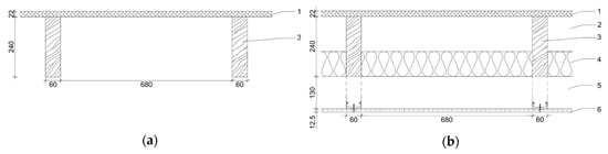
Figure 1.
Cross-sections of model 1a (a) and 1b (b) of the wooden frame floor. 1–OSB board, 2–air gap, 3–wooden joints, 4–mineral wool ρ = 12 kg/m3, 5–air gap, 6–plaster board.
Models 1c and 1d were constructed by successively putting two different heavy floating floors on top of the previously installed model 1b. Both floors consisted of a resilient layer of mineral wool with a self-leveling screed cast on top (2040 kg/m3). The upper slab had a thickness of 25 mm and 60 mm respectively (Figure 2). Technical data on the principal components of the floor are specified in Table 1.
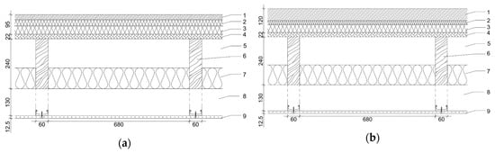
Figure 2.
Cross-sections of model 1c (a) and 1d (b) of the wooden frame floor. 1–self-leveling screed, 2–mineral wool ρ = 150 kg/m3, 3–mineral wool ρ = 107 kg/m3, 4–OSB board, 5–air gap, 6–wooden joints, 7–mineral wool ρ = 12 kg/m3, 8–air gap, 9–plaster board.

Table 1.
Specification of the wood frame floors (models 1a–d).
Models 1e and 1f were constructed by removing the heavy floating floors, modifying the basic floor structure and applying lightweight floor systems. OSB panels were cut into smaller pieces and installed between joists (Figure 3). Pockets formed in this way were filled with a 130 mm layer of expanded clay aggregate with a bulk density of 500 kg/m3 overtopping the joists. Finally, in model 1e the aggregate was covered with 22 mm thick dry screed-boards (density of 1680 kg/m3), whereas for model 1f this configuration was rearranged by installing a 20 mm thick layer of heavy mineral wool with a density of 150 kg/m3 beneath the boards (Figure 4 and Table 2).
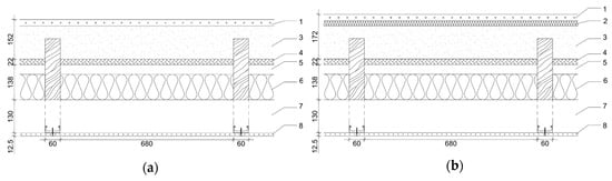
Figure 3.
Cross-sections of model 1e (a) and 1f (b) of the wooden frame floor. 1 – dry screed board, 2 – mineral wool ρ = 150 kg/m3, 3 – expanded clay aggregate, 4 – OSB board, 5 – air gap, 6 – mineral wool ρ = 12 kg/m3, 7 – air gap, 8 – plaster board.
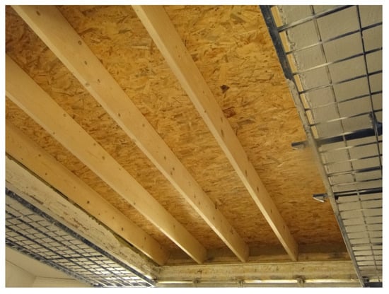
Figure 4.
Basic construction of the wooden floor (model 1a) in a test facility.
Table 2.
Specification of the wood frame floors (models 1e–f).
A metal frame floor (model 2) was constructed with 300 mm steel trusses made of cold-formed profiles. The trusses were arranged in a modular spacing of 600 mm. The upper deck was made of a 1.3 mm thick profiled sheet screwed directly to the trusses. The sheeting was covered with a 40 mm concrete slab (density of 2400 kg/m3) cast on a wood-fiber insulating board, 10 mm thick, with a density of 250 kg/m3 (model 2a). Model 2b was constructed by applying an additional insulation inside the floor, which was made of glass wool (12 kg/m3), 100 mm thick. Next, two models were created by installing a ceiling made of plasterboard panels. The ceiling was supported with 12 mm metal channels spaced at a distance of 400 mm, which were mounted on the bottom side to the truss. Resilient dividers were used between trusses and channels to suppress structural paths of sound transmission between the main floor structure and the ceiling. Single, 12.5 mm plasterboard panels (815 kg/m3) were used in the ceiling of model 2c, whereas double 2 × 12.5 mm boards were applied in model 2d. Cross-sections of all models are given in Figure 5 and technical data on the components of the floors are presented in Table 3.
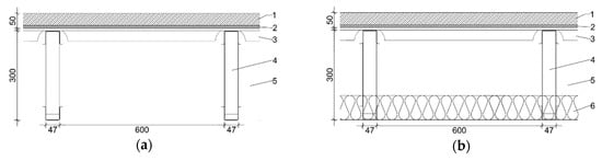
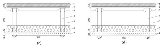
Figure 5.
Cross-sections of a metal frame floor: (a) Basic construction (model 2a); (b) Construction filled with a glass wool (model 2b); (c) Construction with a single plasterboard (model 2c); (d) Construction with a double plasterboard. 1 – concrete slab, 2 – wood-fiber insulating board, 3 – profiled sheet, 4 – steel trusses, 5 – air gap, 6 – glass wool ρ = 12 kg/m3, 7 – plasterboard.
Table 3.
Specification of the metal frame floors (models 2a–d).
Technical data on the resilient materials used in all floating floors are specified in Table 4. The numbers in brackets corresponds to the respective figure captions.
Table 4.
Specification of the resilient materials used in all floating floors.
2.2. Measurement Methods
Airborne and impact sound insulation measurements were carried out in accordance with EN ISO 10140. Single number values were calculated according to EN ISO 717-1 and EN ISO 717-2 respectively. Two wideband speaker cabinets placed in the corners of the sending room were used as airborne sources emitting pink noise. The impact sound insulation was determined with the use of a standard tapping machine placed successively at five different positions on the floor, in accordance with the standard’s recommendations. Average sound pressure levels in 1/3 octave bands were measured in the source and in the receiving room. Continuously moving microphones were used for the space averaging; the sound pressure level was integrated over time and space. Reverberation time was determined in the receiving room to enable the calculation of sound reduction index R, as well as the normalized impact sound pressure level, Ln. The source and receiving rooms were of irregular shape with no parallel walls and were separated by a structural acoustic break (Figure 6).
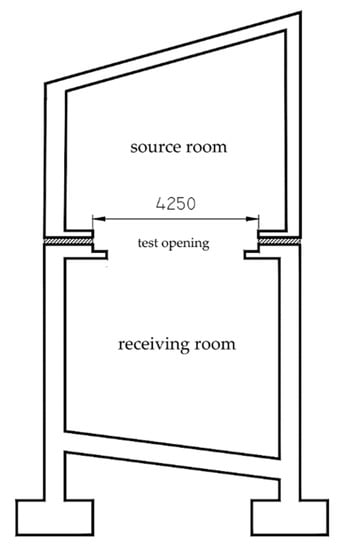
Figure 6.
Vertical cross-section of the test facility.
3. Results and Discussion
3.1. Wooden Floors
3.1.1. Basic Structures
The results of laboratory measurements conducted for the basic structure of a wooden floor (model 1a) and a floor with a suspended ceiling (model 1b) are presented in Figure 7. The single number values of airborne and impact sound insulation are collected in Table 5. The acoustic performance of a bare floor was not satisfactory and did not meet any legal requirements or the expectations of the users. The application of a suspended ceiling increased the values of airborne single number quantities by about 20 dB. A similar improvement of impact sound insulation was also noticed. The low frequency enhancement, however, measured by employing C50–5000 and CI,50–3150 spectrum adaptation terms for the assessment, was lower by 4–5 dB. The results were not satisfactory even for users with very low expectations [24].
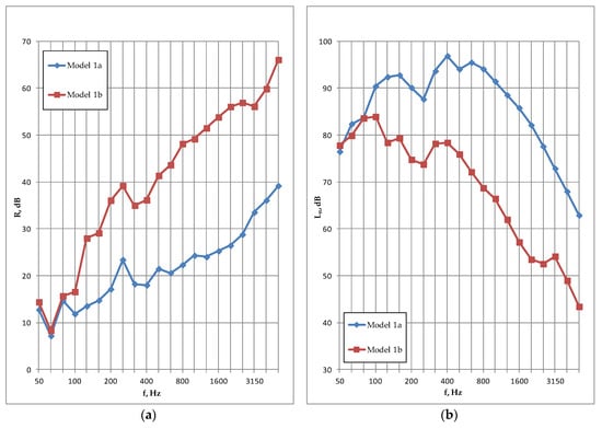
Figure 7.
Airborne (a) and impact (b) sound insulation test results of the wooden floor (models 1a and 1b).
Table 5.
Single-number quantities of wooden frame floors.
Local improvement of sound insulation was observed at 250 Hz for both investigated floors, with and without the ceiling, for both airborne and impact sound insulation characteristics (Figure 7). This effect results from the geometry of the basic floor structure, probably resulting from the distance between the joists (see Section 3.1.2.).
3.1.2. Heavy Floating Floors
The basic floor with suspended ceiling (model 1b) was equipped successively with two different heavy floating floors made of self-leveling screed (models 1c and 1d) cast on a resilient layer of mineral wool. The frequency-dependent results are shown in Figure 8, while the single number values are given in Table 5. The airborne sound insulation is promising; however, the negative values of spectrum adaptation terms are rather high, particularly when the extended range of frequency is considered (Table 5). The values of Rw index are almost the same for both models, but the solution with a thicker slab is more favorable when the term C is used for the assessment.
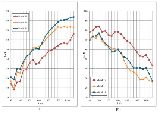
Figure 8.
Airborne (a) and impact (b) sound insulation test results of models 1c and 1d of the wooden floor compared to the basic construction (model 1b).
Surprisingly, despite the different resilient insulating layers and the different upper slabs used in both cases, the impact sound insulation of models 1c and 1d are very similar when taking into consideration only single-number quantities. However, when looking at the frequency dependent sound insulation characteristic, the values are significantly different above 400 Hz. The thicker slab gives slightly worse results in high frequencies, which leads to a higher value of the Ln indicator. The quantities, however, are still too high and far from satisfactory in multi-occupancy residential buildings. In addition, the positive values of term CI, observed for both models, prove that low frequency performance may pose a challenging problem [25,26,27].
Equally surprising is the fact that the significantly increased mass of the floor, resulting from the larger thickness of the upper slab in model 1d (60 mm), did not improve significantly the airborne sound insulation, compared to the considerably thinner screed used in model 1c (25 mm). The thicker plate brought about better results in the low frequency area resulting in higher values of Rw + C50-5000 index. Thus, it can be concluded that it is possible to optimize slab thickness but the effect is not the same as that expected for massive floor structures [28].
Increased sound insulation at 250 Hz was also noted for the floating floor but it was not as distinct as in the case of model 1 (Figure 8). The half wavelength of 250 Hz corresponds to the distance between the main joists. This may imply that the niches created between joists work as half-wave resonators [29]. Other wooden constructions examined recently, which were not considered in this paper, behave similarly. Improvement of sound insulation at 250 Hz was observed in the case of a floor with joists spaced at a distance of 630 mm, whereas reduction of the distance to 430 mm displaced the increase to 400 Hz.
Airborne sound insulation of the floor was tested several times during the curing time of the upper slab. Measurements were carried out over one-week intervals. Only minor changes in sound insulation were observed: model 1d showed a small improvement in frequencies above 800 Hz following the aging of the screed. After four weeks of curing, the impact sound insulation was also tested over one-week intervals. No changes were observed.
3.1.3. Lightweight Floating Floors
The heavy floating floors used in models 1c and 1d were replaced with lightweight systems made of expanded clay aggregate and dry screed-boards at the top (models 1e and 1f). The OSB panels were cut into smaller boards and placed between wooden joists, making more space for the loosely poured aggregate. This modified the structural paths of sound transmission and also changed the static scheme of the floor (Figure 9).
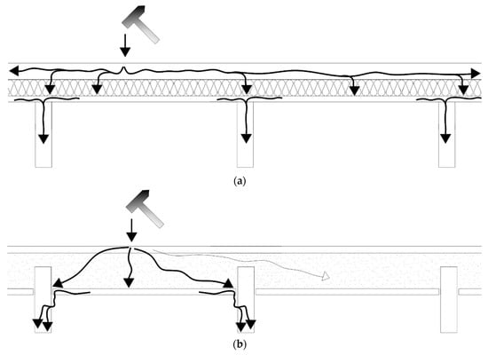
Figure 9.
Structural paths of sound transmission in the case of: (a) Heavy floating floor with a concrete slab on the top; (b) Lightweight floating floor built with dry-screed boards and expanded clay aggregate.
The frequency-dependent results are presented in Figure 10, and the single number values are shown in Table 5. The floating floor applied in model 1e had significantly different structure than those used in models 1c and 1d, and the dynamic stiffness of the resilient layers were also considerably different. In spite of these facts, the airborne and impact sound insulation were quite similar in all cases.
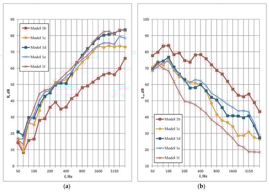
Figure 10.
Airborne (a) and impact (b) sound insulation test results of all models of the wooden floor compared to the basic construction (model 1b).
Basically the dynamic stiffness of the resilient layer and the surface mass of the top plate have the greatest influence on the floating system performance. Generally the lower stiffness and the higher mass per unit area, the better acoustic performance. This is more exactly stated in the empirical formula on the improvement of the impact sound insulation of the floating floor [30]:
where m’ is mass per unit area of the floating floor (kg/m2) and s’ is dynamic stiffness per unit area of the resilient layer (MN/m3). Putting an additional layer of mineral wool under the top slab (model 1f) considerably increased the impact sound insulation and also slightly improved the airborne performance. The unfavorable values of spectrum adaptation terms, however, prove once again that substantial enhancement of the low frequency performance of a lightweight floor is very difficult regardless of the type of floating floor.
ΔLw = 13log(m’) − 14.2log(s’) + 20.8 dB,
In the case of models 1e and 1f, the top panel had significantly lower static stiffness and higher internal damping than concrete slab used in models 1c and 1d. In effect the interlayers beneath it were excited locally depending on the impact noise source position, whereas in the case of a heavy screed the layers were excited on the whole floor surface. Dividing of the floating floor into smaller pieces reduces the radiating surface area and then the impact sound pressure level beneath the floor [31]. In addition, as the OSB panels were cut into smaller pieces and fastened between joists, the energy was transmitted to the joists via their vertical sides through additional battens supporting the plates.
These effects increased the attenuation of the system in models 1e and 1f, but on the other hand the attenuation was reduced because of the higher dynamic stiffness of the insulating layer used in these models.
3.2. Metal Frame Floor
The results of acoustic measurements taken for the metal frame floor are presented as single-number quantities in Table 6. The airborne and impact sound insulation plots are shown in Figure 11.
Table 6.
Single-number quantities of a metal frame floor.
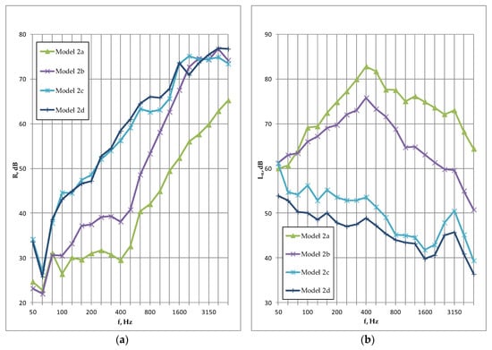
Figure 11.
Airborne (a) and impact (b) sound insulation test results of a metal frame floor.
The acoustic performance of a basic structure (model 2a), consisting of a metal frame, an upside sheeting and a floating floor, is insufficient in terms of both airborne and impact sound transmissions. A distinct decrease in frequency-dependent sound insulation characteristics may be observed at 400 Hz, which is related to the resonance of the floating floor system resulting from the relatively high dynamic stiffness of the resilient layer (Figure 11). The single-number quantities are far too low to provide adequate acoustic comfort in a residential building.
The absorption inserted into the cavity on the bottom side of the floor, consisting of a 100 mm layer of glass wool, substantially improved the single-number values but they are still far from meeting even the lowest acoustic requirements (model 2b). The enhancement of sound insulation due to the absorbing material ranges from about 7 dB in the middle frequency bands to around 13 dB at high frequencies. The initial effect at 400 Hz may also be observed in the case of model 2b.
The application of a suspended ceiling, which closed the floor structure on the bottom side (models 2c and 2d), changed the shape of the airborne sound insulation curves considerably. This is typical of a double lightweight frame structure with a boarding fastened on both sides to different, structurally separated parts of the frame. Airborne sound insulation improved mainly in the low and middle frequency bands, whereas impact sound insulation increased in a significantly wider range, also including high frequencies. The decrease observed at 400 Hz in the case of models 2a and 2b essentially disappeared; however, it is still slightly evident in the impact sound insulation plots (Figure 11b). In the case of models 2c and 2d, a distinctive increase of impact sound pressure level also appeared at 3150 Hz. This is related to the coincidence effect of the plasterboard panels [32,33,34].
Model 2d was constructed by screwing the second layer of plasterboard to the single ceiling used in model 2c. In consequence, airborne sound insulation slightly improved, and the normalized impact sound pressure level Ln,w decreased by 4 dB, which makes its value acceptable in residential buildings. The values of CI and CI,50-3150 spectrum adaptation terms are negative for all variants of model 2. These mean better acoustic performance in the low frequency range than that observed in the case of the wooden floors, where the values were positive in each case. The airborne spectrum adaptation terms C and CI,50–3150 are also advantageous in comparison with wooden floors. This behavior of metal structures, in acoustic terms, is more similar to that of massive floors than lightweight frame partitions. The single-number quantities obtained for models 2c and 2d are promising (Table 6).
3.3. Comparison of Selected Wooden and Metal Models
Figure 12 provides a graphical comparison of sound insulation plots of selected floor structures with similar configuration. They consisted of metal or wooden frames, heavy floating floors, air gaps and insulating layers made of mineral wool positioned inside the plenum. In all cases, the suspended ceiling was made of a single plasterboard panel fastened to metal profiles/hangers. The highest airborne sound insulation in the low frequency range may be observed in the case of the metal floor (model 2c). This could be explained by the use of special channels and resilient hangers for installing the suspended ceiling. In the range of high frequencies, the best results are obtained by the wooden floor (model 1d), which had the thickest layer of the floating floor slab. Considering impact sound insulation, again the best performance at low frequencies was shown by the metal floor (model 2c), whereas wooden floors displayed lower impact sound pressure levels at high frequencies.

Figure 12.
Airborne (a) and impact (b) sound insulation test results of both floor structures.
Table 7 presents single-number quantities of the three similar wood and metal floor structures. In terms of airborne sound insulation, especially when extended frequency ranges are considered, the best performing model is the metal frame floor (model 2c). A similar conclusion may be drawn in terms of impact sound insulation. The quantities prove that the metal floor may be used in residential buildings, provided that the flanking transmission is effectively suppressed. In the case of wooden floors, further improvement of impact sound insulation is necessary (see model 1f).
Table 7.
Single-number quantities of the selected floor structures.
4. Conclusions and Further Research
The aim of the study was to develop effective insulating layers of lightweight floors intended for use in residential buildings. The floor system should satisfy legal requirements in terms of airborne and impact sound insulation. The research was conducted experimentally, based on laboratory measurements taken in a standard test facility. Ten different models of wood and metal floors were considered.
The basic structures of the investigated floors exhibited insufficient acoustic performance, rendering them unsuitable for use in any residential building, without additional insulating layers. An effective floating floor and suspended ceiling may substantially improve their sound insulation; however, the mitigation of impact noise is critical. The acoustic properties of a basic floor depend on its geometry, which may influence in a way the properties of the final construction. This effect will be thoroughly analyzed at a next stage of this work.
In the case of wooden floors, unfavorable values of spectrum adaptation terms were observed for each investigated model, especially when the terms were determined in extended frequency ranges. This refers to both airborne and impact sound insulation and highlights the low frequency behavior of these structures. Cutting the supporting OSB into smaller pieces, which are then put between the joists, was profitable in acoustic terms, but it changed the static scheme of the floor. The fact that the substantial increase of the thickness (mass) of the upper slab of a floating floor did not cause any significant improvement in sound insulation in terms of both airborne and impact sound transmission was surprising.
The final models of the metal frame floor showed promising acoustic performance, and their sound insulation may be acceptable for multi-occupancy residential buildings. The values of airborne and impact spectrum adaptation terms were favorable in comparison with those obtained for the examined wooden floors. They are similar to the values usually obtained in traditional massive structures rather than lightweight frame partitions. The low frequency behavior of the metal floor is particularly interesting, as the impact CI and CI,50–3150 terms are negative, which is unusual for this type of frame structures. This proves that the low frequency transmission is effectively suppressed in this case. The local reduction of sound insulation of basic models (2a and 2b) at 400 Hz was due to the resonance of the floating floor system and the relatively high dynamic stiffness of the resilient layer used under the upside screed. This adverse effect was suppressed by applying the suspended ceiling on the bottom side.
The results show how different lightweight floor components influence the floor’s acoustic performance and how the insulating layers cooperate when applied together. The acoustic data collected for the investigated frame floors and the recorded effects of additional layers will be used for further investigations, the optimization of lightweight floor structures and the modeling of their acoustic performance.
Author Contributions
Conceptualization, J.N.; methodology, J.N.; investigation, Ł.N.; data curation, Ł.N.; writing—original draft preparation, Ł.N.; writing—review and editing, J.N.; visualization, Ł.N.; supervision, J.N. All authors have read and agreed to the published version of the manuscript.
Funding
This research received no external funding.
Conflicts of Interest
The authors declare no conflict of interest.
References
- Nurzyński, J. Experimental study on the sound insulation of composite panels intended for use in a building. In INTER-NOISE and NOISE-CON Congress and Conference Proceedings; Sociedade Portuguesa de Acústica: Lisbon, Portugal, 2010. [Google Scholar]
- Zhang, B.; Kermani, A.; Fillingham, T. Vibrational performance of timber floors constructed with metal web joists. Eng. Struct. 2013, 56, 1321–1334. [Google Scholar] [CrossRef]
- Homb, A.; Guigou-Carter, C.; Hagberg, K.; Schmid, H. Impact sound insulation of wooden joist constructions: Collection of laboratory measurements and trend analysis. Build. Acoust. 2016, 23, 73–91. [Google Scholar] [CrossRef]
- Höller, C.; Zeitler, B.; Sabourin, I. Direct airborne and impact sound insulation of steel-framed floors for mid-rise constructions. In Proceedings of the INTER-NOISE and NOISE-CON Congress and Conference Proceedings, San Francisco, CA, USA, 9–12 August 2015. [Google Scholar]
- Caniato, M.; Bettarello, F.; Fausti, P.; Ferluga, A.; Marsich, L.; Schmid, C. Impact sound of timber floors in sustainable buildings. Build. Environ. 2017, 120, 110–122. [Google Scholar] [CrossRef]
- Nurzyński, J. Is Thermal Resistance Correlated With Sound Insulation? Energy Procedia 2015, 78, 152–157. [Google Scholar] [CrossRef]
- Semprini, G.; Cocchi, A.; Marinosci, C. Possible correlation between acoustic and thermal performances of building structures. J. Acoust. Soc. Am. 2008, 123, 3609. [Google Scholar] [CrossRef]
- Di Bella, A.; Granzotto, N.; Pavarin, C. Comparative analysis of thermal and acoustic performance of building elements. In Proceedings of EAA-Forum Acusticum; The Polish Acoustical Society: Krakow, Poland, 2014. [Google Scholar]
- Caniato, M.; Bettarello, F.; Ferluga, A.; Marsich, L.; Schmid, C.; Fausti, P. Acoustic of lightweight timber buildings: A review. Renew. Sustain. Energy Rev. 2017, 80, 585–596. [Google Scholar] [CrossRef]
- Šujanová, P.; Rychtáriková, M.; Mayor, T.S.; Hyder, A. A healthy, energy-efficient and comfortable indoor environment, a review. Energies 2019, 12, 1414. [Google Scholar] [CrossRef]
- Fiala, L.; Konrád, P.; Maděra, J.; Černý, R. Data acquisition and acoustic modeling of heterogeneous building materials. AIP Conf. Proc. 2019, 2116, 070006. [Google Scholar] [CrossRef]
- Kočí, J.; Maděra, J. Optimization procedure for design of geometrical configuration of acoustic bricks. AIP Conf. Proc. 2018, 1978, 080004. [Google Scholar] [CrossRef]
- Martins, C.; Santos, P.; Almeida, P.; Godinho, L.; Dias, A. Acoustic performance of timber and timber-concrete floors. Constr. Build. Mater. 2015, 101, 684–691. [Google Scholar] [CrossRef]
- Homb, A.; Guigou-Carter, C.; Rabold, A. Impact sound insulation of cross-laminated timber/massive wood floor constructions: Collection of laboratory measurements and result evaluation. Build. Acoust. 2017, 24, 35–52. [Google Scholar] [CrossRef]
- Emms, G.; Chung, H.; Mcgunnigle, K.; Dodd, G. Improving the Impact Insulation of Light Timber Floors. In Proceedings of the 1st Joint Australasian Acoustical Conference, Christchurch, New Zealand, 20–22 November 2006. [Google Scholar]
- Ljunggren, F.; Ågren, A. Potential solutions to improved sound performance of volume based lightweight multi-storey timber buildings. Appl. Acoust. 2011, 72, 231–240. [Google Scholar] [CrossRef]
- Ljunggren, F.; Ågren, A. Elastic Layers to Reduce Sound Transmission in Lightweight Buildings. Noise Notes 2013, 12, 3–18. [Google Scholar] [CrossRef]
- Ingelaere, B.; Wuyts, D. Impact sound measurements on wooden floors. Project AH+, part 6. In Proceedings of the INTER-NOISE and NOISE-CON Congress and Conference Proceedings, Innsbruck, Austria, 15–18 September 2013; Volume 3, pp. 1979–1987. [Google Scholar]
- De Geeter, L.; Inglaere, B. A new building acoustical concept for lightweight timber frame constructions. In Proceedings of the 43rd International Congress on Noise Control Engineering, Melbourne, Australia, 16–19 November 2014. [Google Scholar]
- Zeitler, B.; Sabourin, I.; Schoenwald, S.; Wenzke, E. On reducing low frequency impact sound transmission in wood framed construction. In Proceedings of the INTER-NOISE and NOISE-CON Congress and Conference Proceedings, New York, NY, USA, 19–22 August 2012; Volume 8, pp. 6653–6662. [Google Scholar]
- Johansson, C. Low-frequency impact sound insulation of a light weight wooden joist floor. Appl. Acoust. 1995, 44, 133–147. [Google Scholar] [CrossRef]
- PN-B-02151-3. Building Acoustics—Protection Against noice in Buildings—Part 3: Requirements Concerning Sound Insulation of Partitions in Buildings and of Building Elements; PKN: Warsaw, Poland, 2015. [Google Scholar]
- EN ISO 10140-5. Acoustics—Laboratory Measurement of Sound Insulation of Building Elements—Part 5: Requirements for Test Facilities and Equipment; PKN: Warsaw, Poland, 2010. [Google Scholar]
- Gover, B.; Bradley, J.; Schoenwald, S.; Zeitler, B. Subjective ranking of footstep and low-frequency impact sounds on lightweight wood-framed floor assemblies. In Proceedings of the 6th Forum Acusticum, Aalborg, Denmark, 26 June–1 July 2011. [Google Scholar]
- Öqvist, R.; Ljunggren, F. Variations in sound insulation from 20 Hz in lightweight dwellings. Noise Control Eng. J. 2018, 66, 56–65. [Google Scholar] [CrossRef]
- Fox, C.; Chung, H. Modeling low-frequency vibration in light-weight timber floor/ceiling systems. J. Acoust. Soc. Am. 2019, 145, 831–846. [Google Scholar] [CrossRef] [PubMed]
- Olsson, J.; Linderholt, A. Low-frequency impact sound pressure fields in small rooms within lightweight timber buildings—Suggestions for simplified measurement procedures. Noise Control Eng. J. 2018, 66, 324–339. [Google Scholar] [CrossRef]
- Nowotny, Ł. Weighted Reduction of Impact Sound Pressure Level for a Floating Floor, According to ISO Standard and Laboratory Measurements. In Proceedings of the 2018 Joint Conference-Acoustics, Ustka, Poland, 11–14 September 2018; pp. 220–225. [Google Scholar]
- Sohn, C.H.; Park, J.H. A comparative study on acoustic damping induced by half-wave, quarter-wave, and Helmholtz resonators. Aerosp. Sci. Technol. 2011, 15, 606–614. [Google Scholar] [CrossRef]
- EN ISO 12354-2. Building Acoustics—Estimation of Acoustic Performance of Buildings from the Performance of Elements—Part 2: Impact Sound Insulation Between Rooms; CEN: Brussels, Belgium, 2017. [Google Scholar]
- Miškinis, K.; Dikavičius, V.; Ramanauskas, J.; Norvaišiene, R. Dependence between reduction of weighted impact sound pressure level and specimen size of floating floor construction. Medziagotyra 2012, 18, 93–97. [Google Scholar] [CrossRef][Green Version]
- Gösele, K.; Schröder, E. Sound insulation in buildings. In Handbook of Engineering Acoustics; Müller, G., Möser, M., Eds.; Springer: Berlin/Heidelberg, Germany, 2013; pp. 137–164. ISBN 9783540694601. [Google Scholar]
- Schneider, M.; Zeitler, B. Radiation efficiency of metal stud plaster-board walls. In Proceedings of the 24th International Congress on Sound and Vibration ICSV, London, UK, 23–27 July 2017. [Google Scholar]
- Reinhold, S.; Schneider, M.; Fischer, H.M. Measured sound insulation of double leaf plasterboard walls—Influence of different construction parameters. In Proceedings of the 42nd International Congress and Exposition on Noise Control Engineering 2013, INTER-NOISE 2013: Noise Control for Quality of Life, Innsbruck, Austria, 15–18 September 2013; Volume 3, pp. 1820–1828. [Google Scholar]


© 2020 by the authors. Licensee MDPI, Basel, Switzerland. This article is an open access article distributed under the terms and conditions of the Creative Commons Attribution (CC BY) license (http://creativecommons.org/licenses/by/4.0/).