Article

Application of Promising Electrode Materials in Contact with a Thin-Layer ZrO2-Based Supporting Electrolyte for Solid Oxide Fuel Cells

by
Denis A. Osinkin
1,2,*,
Ekaterina P. Antonova
1,2,
Alena S. Lesnichyova
1,2,
Evgeniy S. Tropin
1,2,
Mikhail E. Chernov
3,
Efim I. Chernov
3,
Andrey S. Farlenkov
1,2,
Anna V. Khodimchuk
1,2,
Vadim A. Eremin
1,2,
Anastasia I. Kovrova
1,
Anton V. Kuzmin
1,2 and
Maxim V. Ananyev
1,2
1
Institute of High-Temperature Electrochemistry UB RAS, Yekaterinburg 620137, Russia
2
Institute of Chemical Engineering, Ural Federal University, Yekaterinburg 620002, Russia
3
“Ekon” Ltd, Obninsk 249037, Russia
*
Author to whom correspondence should be addressed.
Energies 2020, 13(5), 1190; https://doi.org/10.3390/en13051190
Submission received: 26 December 2019 / Revised: 26 February 2020 / Accepted: 4 March 2020 / Published: 5 March 2020

Abstract

:
The paper presents the results of an investigation into thin single- and triple-layer ZrO2-Sc2O3-based electrolytes prepared using the tape-casting technique in combination with promising electrodes based on La2NiO4+δ and Ni-Ce0.8Sm0.2O2-δ materials. It is shown that pressing and joint sintering of single electrolyte layers allows multilayer structures to be obtained that are free of defects at the layer interface. Electrical conductivity measurements of a triple-layer electrolyte carried out in longitudinal and transverse directions with both direct and alternating current showed resistance of the interface between the layers on the total resistance of the electrolyte to be minimal. Long-term tests have shown that the greatest degradation in resistance over time occurs in the case of an electrolyte with a tetragonal structure. Symmetrical electrochemical cells with electrodes fabricated using a screen-printing method were examined by means of electrochemical impedance spectroscopy. The polarization resistance of the electrodes was 0.45 and 0.16 Ohm∙cm2 at 800 °C for the fuel and oxygen electrodes, respectively. The distribution of relaxation times method was applied for impedance data analysis. During tests of a single solid oxide fuel cell comprising a supporting triple-layer electrolyte having a thickness of 300 microns, a power density of about 160 mW/cm2 at 850 °C was obtained using wet hydrogen as fuel and air as an oxidizing gas.

1. Introduction

The application of high-temperature solid oxide electrochemical devices presents great opportunities for energy conversion; for example, the use of solid oxide fuel cells (SOFCs) for electricity production [1,2,3,4,5]. In conventional SOFCs, thick layers of Y-doped ZrO2 electrolyte (YSZ) are used as ionic-conducting materials. However, in this case, a considerable part of the produced energy is lost due to ohmic electrolyte resistance.
One of the most promising approaches to the reduction of ohmic resistance is the application of electrolyte thin films having a thickness of about 10–30 µm [6,7,8]. Due to technological issues involved in the manufacture of such thin films, their formation should be carried out on a porous supporting substrate (cathode [9,10,11], anode [12,13,14], metal interconnector [15,16,17]) in order to ensure the mechanical strength of the cell. For this reason, questions arise concerning the production technology of supporting substrates. Another way to reduce ohmic resistance involves the use of thin (150–250 µm) supporting electrolyte layers manufactured from electrolyte materials having a higher ionic conductivity than conventional YSZ—for example, Sc-stabilized ZrO2 (SSZ). The conductivity of ZrO2-Sc2O3 solid solutions, which reaches a maximum at concentrations of Sc2O3 9–12 mol.%, is significantly higher than that of YSZ at similar dopant concentrations [18,19,20]. However, the cubic ZrO2-Sc2O3 phase is only stable at high temperatures; with a decrease in temperature, it partially transfers to the ordered rhombohedral phase, whose conductivity is much lower [19,20,21]. For this reason, solid solutions undergo rapid electrical conductivity degradation during long-term testing [21,22]. A common approach to stabilizing the cubic phase in fluorite-like solid solutions containing scandium is to introduce a small amount of yttrium oxide or oxides of other rare earth elements having a large cation radius [19,20,21]. However, reducing the thickness of the supporting electrolyte also reduces its strength. From this point of view, tetragonal phases based on ZrO2 are of great interest [23] despite their much lower conductivity. One of the most promising approaches to the creation of a supporting electrolyte membrane combining low resistance with high mechanical strength involves the fabrication of multilayer electrolyte structures combining both cubic and tetragonal phases [23,24].
Other promising approaches to improving the performance of SOFCs include the use of high-efficient electrode materials, e.g., La2NiO4+δ, which exhibit enhanced performance at low temperatures due to high oxygen exchange and diffusion coefficient values [25,26,27]; the use of composite electrode materials to extend the electrochemical active zone [28,29,30,31]; and the application of two-layered electrode structures (functional and current collector layers) [32,33,34,35].
In our study, we attempted to combine two of the above-mentioned approaches, i.e., the application of triple-layer Sc2O3-ZrO2-based electrolytes acting as the supporting SOFC electrolyte with two-layered La2NiO4+δ-based materials serving as an oxygen electrode. In the present paper, data concerning the functional properties of single- and triple-layer Sc2O3-ZrO2-based electrolytes produced by the tape-casting method are presented along with the results of electrochemical studies for symmetrical cells and SOFCs based thereon.

2. Materials and Methods

The studies were performed on three types of solid electrolyte: a single-layer electrolyte of the composition ZrO2 + 6 mol.% Sc2O3 having a tetragonal structure (hereinafter t.SSZ), a single-layer electrolyte of the composition ZrO2 + 10 mol.% Sc2O3 + 1 mol.% Y2O3 with a cubic structure (hereinafter c.SSZ), as well as a triple-layer electrolyte with an internal c.SSZ layer and external t.SSZ layers. For the fabrication of electrolyte layers, single-phase powders of appropriate compositions having a particle size of about 200–500 nm, manufactured by JSC “NeoChem” (Moscow, Russia), were used.
The electrolyte substrates were produced using the tape-casting technique with equipment developed by “Ekon” Ltd, Obninsk, Russia. The formation of a triple-layer structure was carried out by joint pressing of green body layers. The final sintering of the single-layer and triple-layer electrolytes was carried out at 1600 °C. The thickness of the single-layer electrolyte was about 150 μm, while the triple-layer electrolyte had a thickness of around 300 μm.
In order to prevent chemical reactivity between the electrolyte and La2NiO4+δ-based cathode, a barrier layer of Ce0.8Sm0.2O2-δ was formed on the surface of the electrolyte by means of the dip-coating method. The final thermal treatment of the samples following dip-coating was performed at a temperature of 1200 °C for 1 h with a heating rate of 50 °C per hour. In order to increase the thickness of the barrier film, the procedure was repeated twice.
The oxygen electrode consisted of two layers: a functional layer having the composition 49 wt.% La2NiO4+δ + 49 wt.% Ce0.8Sm0.2O2-δ + 2 wt.% CuO (LNO-SDC) and a current collector layer with the composition 98 wt.% LaNi0.6Fe0.4O3-δ + 2 wt.% CuO (LNF). For composite preparation, the LaNi0.6Fe0.4O3-δ, La2NiO4+δ, and Ce0.8Sm0.2O2-δ powders were mixed in isopropyl in corresponding ratios. A 56 wt.% NiO + 44 wt.% Ce0.8Sm0.2O2-δ (NiO-SDC, after reduction Ni-SDC) composite was used as a fuel electrode.
Symmetrical electrochemical cells, as well as fuel cells having planar construction, were prepared using the screen-printing method. The t.SSZ single-layer and t.SSZ/c.SSZ/t.SSZ triple-layer electrolytes were used for electrochemical and fuel cells, respectively. In the case of symmetrical cells, both electrodes were sintered in one step. For fuel cells, the fuel electrode (anode) was initially formed and sintered, then a second step, consisting of oxygen electrode (cathode) preparation, took place. Sintering conditions were 1100 °C for 1 h and 1050 °C for 2 h for the functional and the collector layers of the cathode, respectively; for the anode, sintering took place at 1400 °C for 3 h. In the case of SOFC tests, the electrodes were impregnated with solutions of electrochemically active oxides following sintering. The impregnation procedure was performed with saturated solutions of praseodymium nitrate (for the cathode) and cerium nitrate (for the anode). After impregnation, nitrates were decomposed at 600 °C in air. The content of corresponding oxides in the electrodes following heat treatment was about 1 mg/cm2.
The phase composition of the materials was verified by X-ray powder diffraction (XRD) in Cu-radiation (λ(Kα1) = 1.54 Å) at room temperature in ambient air (D-MAX-2200 RIGAKU). Microstructural investigation was performed using scanning electron microscopy (MIRA 3 LMU, TESCAN) on the cross-sections of the samples. The preparation procedure for the SEM characterization of samples included epoxy impregnation in a vacuum (residual pressure 10−2 atm) and polishing. The element composition analysis of ceramic samples was performed by X-ray fluorescence spectroscopy (XRF-1800, Shimadzu). The error in the determination of element concentration did not exceed five relative percent.
The electrical conductivity of electrolyte samples in both transverse and longitudinal directions was measured by two-probe AC and four-probe DC methods, respectively. For this purpose, electrodes made from Pt wire were placed on the electrolyte samples and fixed with Pt paste at a temperature of 1000 °C for 1 h. The complex impedance was measured in the frequency range from 100 mHz to 8 MHz using a Zahner Elektrik IM6 electrochemical analyzer.
Symmetrical electrochemical cells were investigated by impedance spectroscopy (IM6, Zahner, and a Solartron 1260 impedance analyzer with 1287 electrochemical interface). Details of the experimental setup are presented elsewhere [36]. For the distribution of relaxation time (DRT) analysis, a program code, developed by the authors of [37] on the basis of Tikhonov’s regularization [38], was applied. For fuel cell studies, the sample was sealed in the measuring cell by high-temperature glass having a transition temperature of 950 °C. Anode reduction was performed at 900 °C in wet hydrogen.

3. Results and Discussion

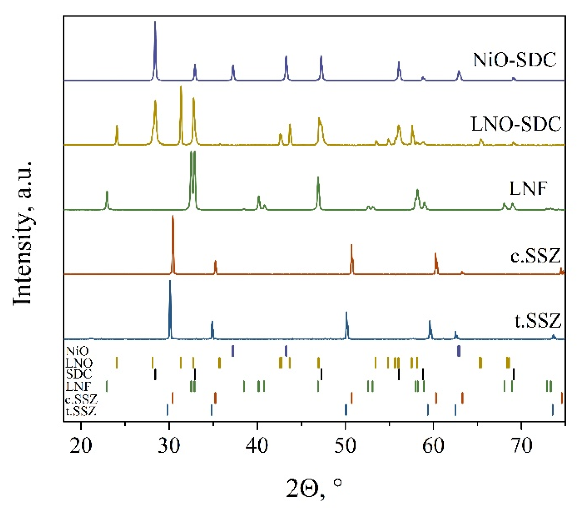
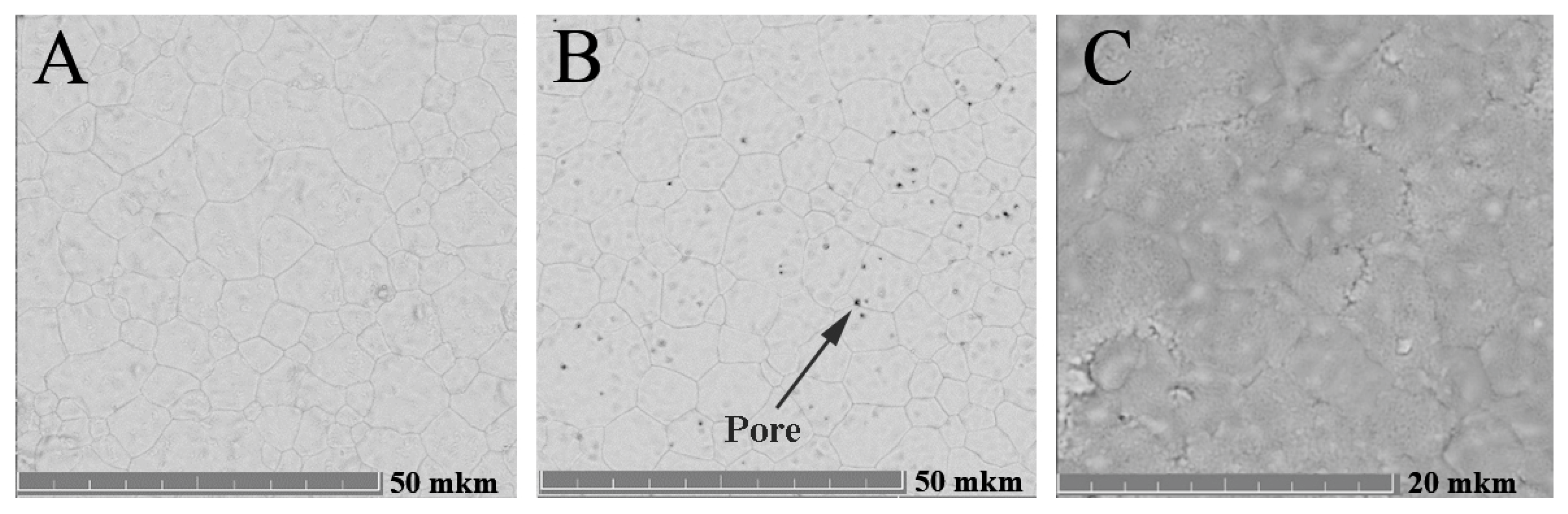
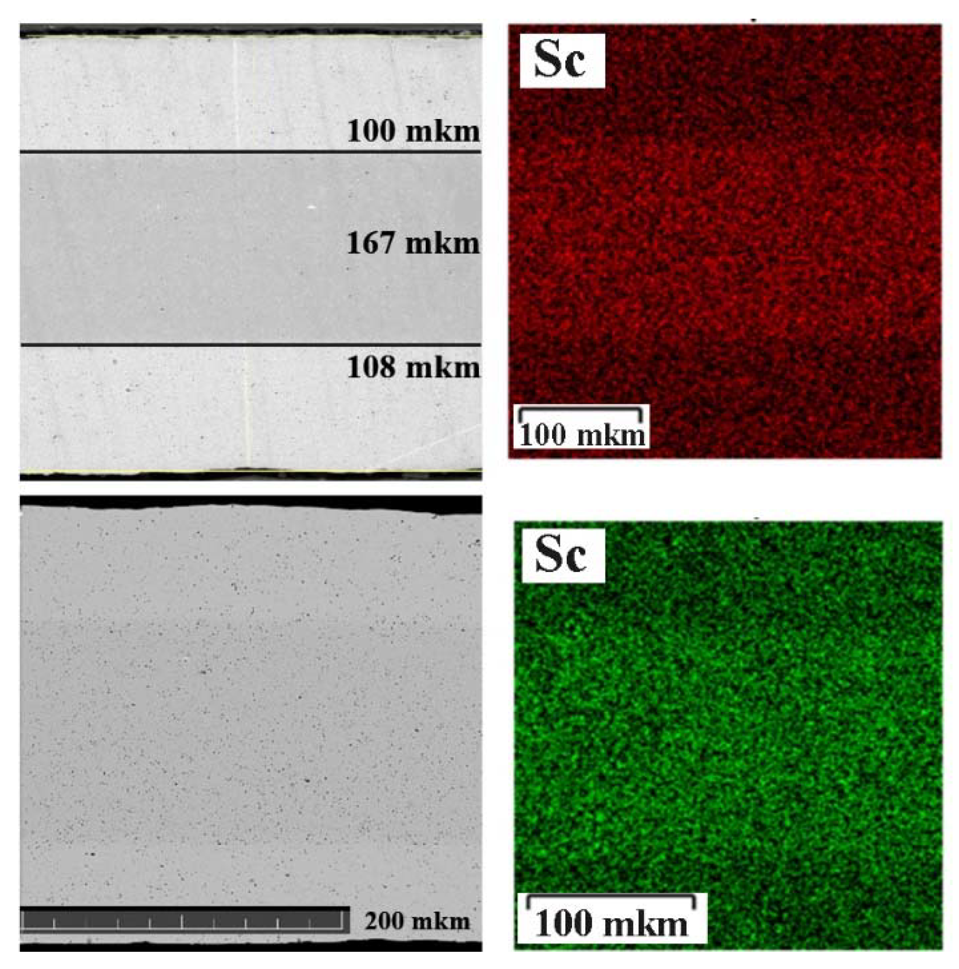
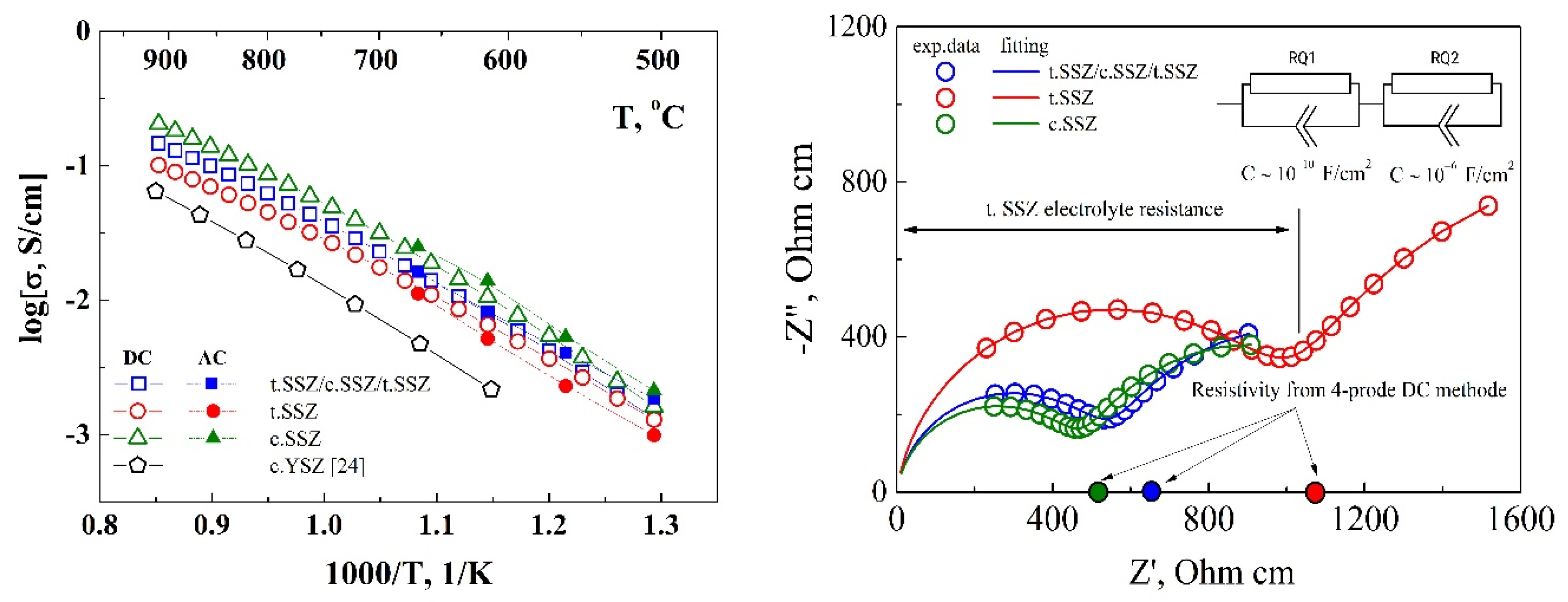
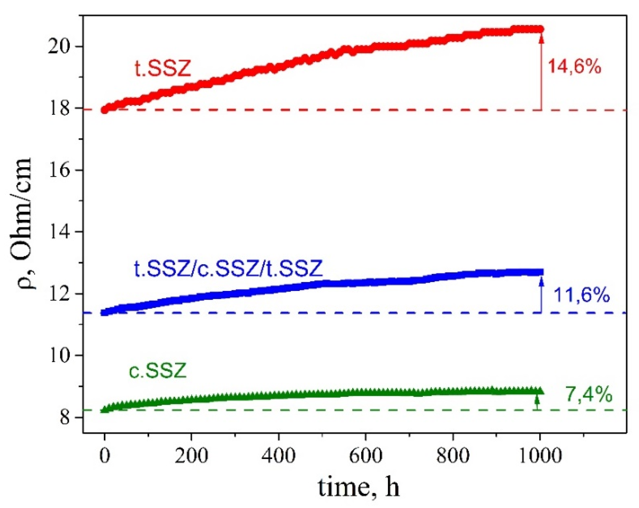
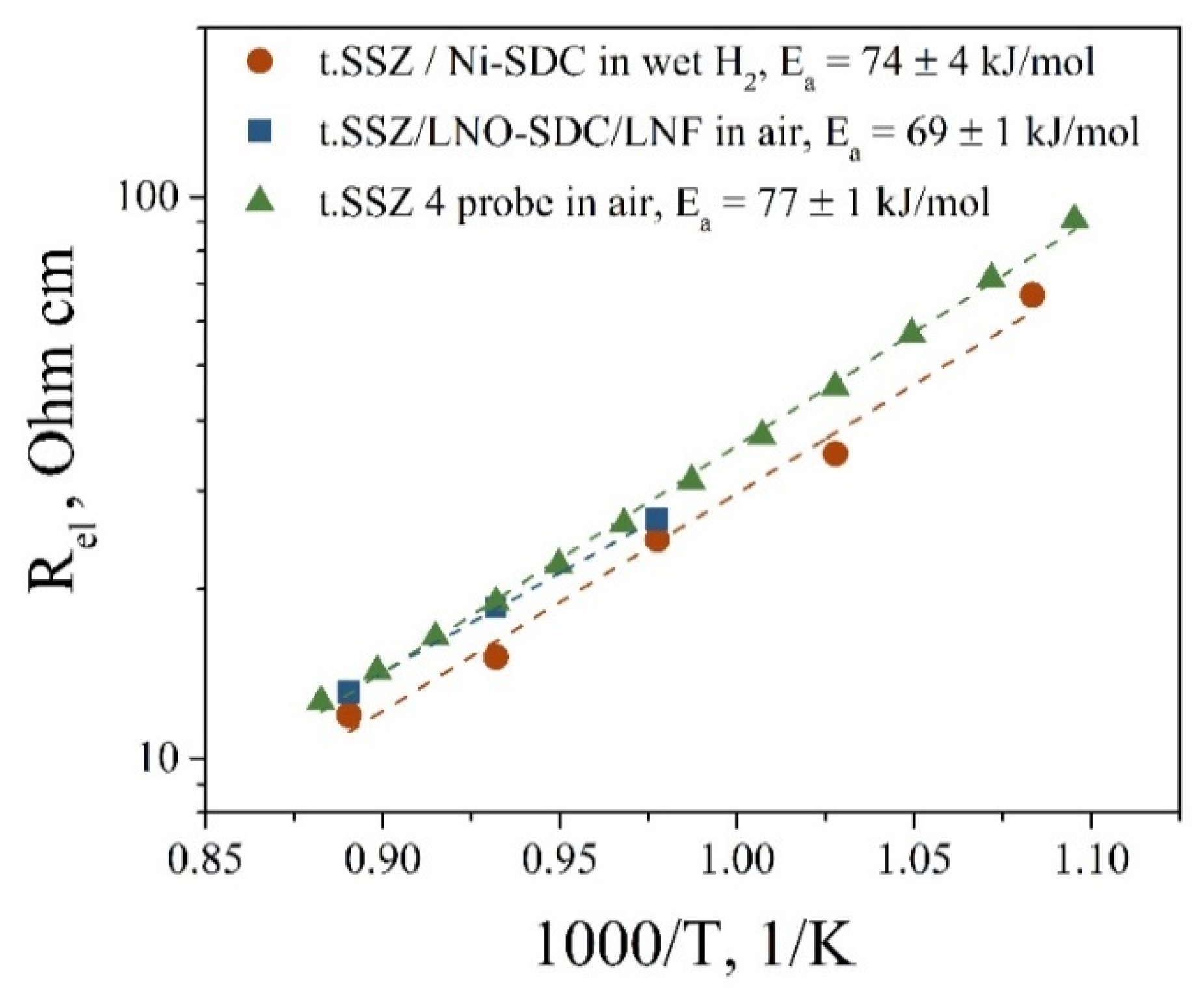
3.1. Electrolyte Properties

XRD analysis confirmed the absence of impurity phases for all materials under investigation, as well as the absence of chemical reactivity between the components of the used composites (Figure 1) because the diffraction patterns contain reflections only for the studied phases. From the SEM images of the electrolyte surface, it is clearly seen that the samples are dense, with an insignificant number of pores on the surface of the c.SSZ electrolyte (black dots on the surface) and almost no pores on the surface of t.SSZ electrolyte (Figure 2). The average grain size, which does not depend on the electrolyte crystal structure, ranges from 3 to 10 µm. Figure 2 additionally shows a SEM image of the Ce0.8Sm0.2O2-δ coating on the electrolyte surface. As can be seen, the coating has good adhesion to the electrolyte surface, without any cracks and defects.
Figure 3 shows SEM images with EDX maps (Sc distribution) of the cross-section t.SSZ/c.SSZ/t.SSZ of the triple-layer ceramic before and after long-time high-temperature exposure (850 °C, 1000 h) the results of which will be presented below. As can be seen from the cross-section SEM image for the triple-layered ceramic, there is no through porosity, and the c.SSZ/t.SSZ interfaces have good quality boundaries both before and after long-term tests.
The results of X-ray fluorescence spectroscopy carried out for both electrolytes are presented in Table 1. The obtained values are in good agreement with those obtained from stoichiometric equations, including hafnium and yttrium impurities, which are accompanying elements for zirconium and scandium, respectively. The presence of minute amounts of iron, chromium, and aluminum can be explained by the technological features of ceramics production, such as the usage of alumina balls for powder mixing.
Figure 4a presents the temperature dependencies of the electrical conductivity of the studied electrolytes in the Arrhenius coordinates. No jumps or inflections on the dependencies corresponding to structural changes are observed. The c.SSZ sample possesses the highest electrical conductivity, which is in good agreement with the literature data given in [18,19,20]. The conductivity of the tetragonal phase is lower, as expected [23], and the conductivity of a three-layer ceramic has an average value compared to t.SSZ and c.SSZ. Figure 4a also shows the conductivity values measured by the impedance method. DC and AC conductivities are well comparable in overlapping temperature ranges. Typical impedance spectra for materials under study at 500 °C are presented in Figure 4b. As could be seen, the EIS spectra of single-layer structures are fitted by two RQ elements. The first RQ1 corresponds to the electrolyte with the value of capacitance about 10−10 F/cm2, and the second RQ2 corresponds to the electrode process with the value of capacitance about 10−6 F/cm2. Additional DC four-probe measurements demonstrate that resistivity of the whole sample is described by the first semicircle, meaning that the second one should be ascribed to the electrode process. Moreover, bulk and grain boundary resistances could not be accurately estimated from the first semicircle of the spectrum. This may be due to the slightly distinguishable composition of the bulk and grain boundaries, as well as the large grain size (≈10 μm) of ceramics, which leads to the low resistance of grain boundaries. At the same time, the EIS spectrum for the t.SSZ/c.SSZ/t.SSZ electrolyte is similar to ones of single-layer structures, which indicates the absence of additional relaxation processes (semicircles) due to resistance at the t.SSZ/c.SSZ interfaces of a three-layer electrolyte. A comparison of the conductivity values for scandium-containing materials and YSZ [24] demonstrate a significant advantage of the former one for application as electrolytes for SOFCs.
During the long-term electrolyte resistance stability tests, the largest increase in resistance was found for t.SSZ, at around 14.6% per 1000 h (Figure 5). For the c.SSZ sample, the resistance value increases by 7.4% over the same period. The relative increase in resistance for a triple-layer electrolyte, which amounts to 11.6% per 1000 h, is mainly associated with the degradation of the tetragonal phase. The degradation mechanism of electrolytes based on zirconium oxide is usually associated with the formation of poorly conducting low-symmetric phases [19,23]. No changes in the phase composition were visible in the X-ray phase analysis of the samples following degradation, probably due to their low content. The element distribution maps for a triple-layer sample show that there is no noticeable redistribution of scandium cations in layers with different contents during a long exposure (Figure 3). The nature of the time dependencies does not differ from those given in the literature [19,22,24]. Over time, the degradation rate slows down over time significantly. A simple equation has been proposed [22] to describe the degradation process:
R τ = R 0 + B τ 1 / 2 ,
where R 0 ,   R τ are the resistivities of the electrolyte prior to degradation, at the instant of time τ, respectively; B is a constant. By extrapolating the time dependencies, according to this equation, we are able to predict that the increase in the resistance of a triple-layer electrolyte will not exceed 17% and 23% after 10,000 and 50,000 h, respectively

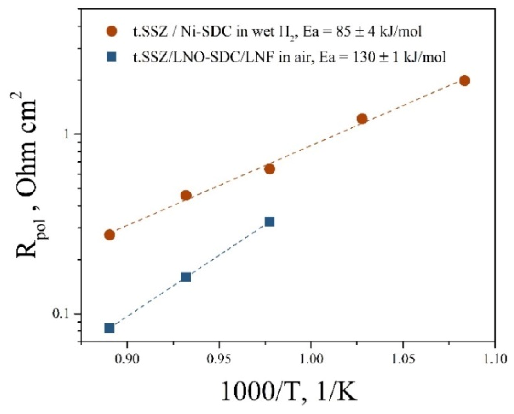
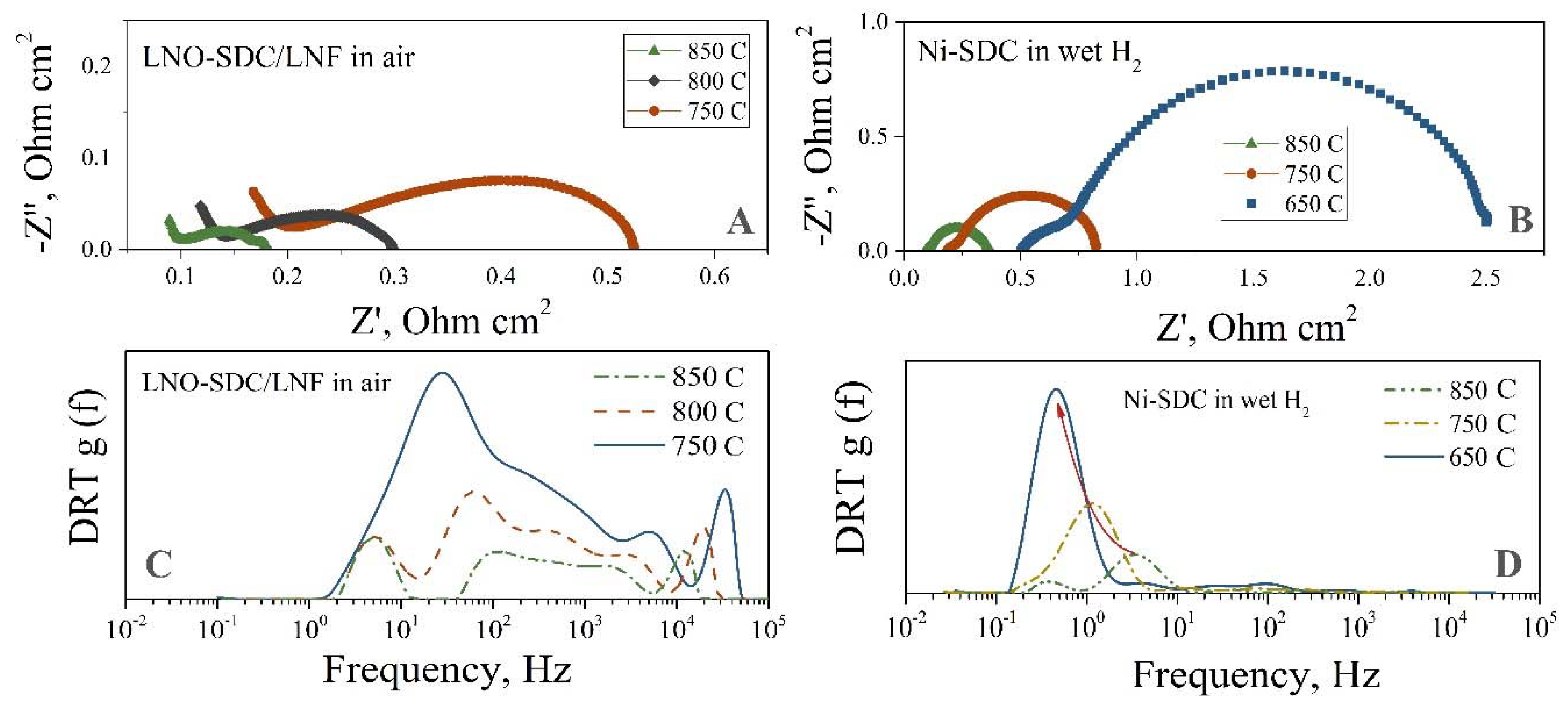
3.2. Electrochemical Cells and Performance

The electrochemical activity of the electrodes in contact with the t.SSZ electrolyte was investigated on the symmetrical electrochemical cells. Measurements were conducted in the temperature range 750–850 °C in an air atmosphere for the LNO-SDC/LNF oxygen electrode; for the Ni-SDC fuel electrode, measurements were carried out in the temperature range 650–850 °C in wet (pH2O = 0.03 atm) hydrogen. Figure 6 presents the comparison between the values of ohmic resistance of the symmetrical electrochemical cells, as extracted from the impedance spectra, and the electrolyte resistance values for t.SSZ as determined by the four-probe DC method. It can be seen that the values obtained using the different measurement techniques, as well as the apparent activation energy values for electrolyte conductivity, are in good agreement. The closeness of the values of the electrolyte resistance and the activation energy obtained by two different methods indicate the absence of chemical interaction between the electrode and electrolyte materials.
Temperature dependencies of polarization resistance for the investigated electrodes are presented in Figure 7. At 800 °C, the polarization resistance (Rη) of the oxygen electrode is about 0.16 Ω·cm2, with an apparent activation energy (Ea) of about 130 kJ/mol. The obtained value of Ea is close to those obtained in [39,40] for similar oxygen double-layer electrodes. Polarization resistance values for the fuel electrode are somewhat higher than those for the oxygen electrode; at 800 °C, the value was around 0.45 Ω·cm2. The apparent activation energy value is about 85 kJ/mol, with such values being quite typical for Ni-SDC electrodes [41].
Impedance spectra for symmetrical electrochemical cells are depicted in Figure 8A,B. For their analysis, the distribution of relaxation times method (DRT) was applied, as it has much higher resolution in comparison to traditional complex nonlinear squares method [42,43]. DRT functions calculated from impedance data are presented in Figure 8C,D. It can be seen that, for oxygen electrodes, the functions consist of several processes. The low-frequency step can be assigned to the gas diffusion [25], while the three steps in the middle-frequency region have been recently identified in [44] as oxygen ion diffusion on the electrode/electrolyte interface, charge transfer in the adsorption layer, and oxygen surface exchange and diffusion in the electrode material.
For fuel electrodes, two peaks at the frequencies of 0.3 and 5 Hz can be found at the DRT function at 600 °C. While the temperature increases the DRT function becomes more complicated. At 850 °C three peaks at the DRT function can be identified at 0.3, 5, and 100 Hz. Similar behavior for the DRT function has been observed previously in [45] for Ni-SDC anodes. Based on the results, obtained in [44] we can conclude that the rate of the hydrogen oxidation is limited by oxygen ionic diffusion in SDC, reactions between adsorbed forms of the potential determining particles on the anode surface as well as the gas diffusion.
The cross-section fuel cell SEM image and SOFC test results are shown in Figure 9. In the temperature range 750–850 °C and using wet hydrogen as a fuel gas, the power density was about 90–160 mW/cm2, respectively. To our knowledge, there is no literary data concerning SOFCs with a 300 µm electrolyte and an LNO-based cathode. However, we can compare our results with those for similar electrolyte-supported SOFCs. For example, in [46] power densities of about 160–270 mW/cm2 were obtained at 800 °C for the SOFC with a 270 µm YSZ electrolyte, two-layer LSM/LSM-YSZ cathode, and Ni-YSZ anode, which is close to our values. The obtained power values are not very high, probably due to the ohmic resistance of the t.SSZ/c.SSZ/t.SSZ electrolyte. Reducing the thickness of the electrolyte will significantly increase the power performance of the SOFC.

4. Conclusions

ZrO2-Sc2O3-based electrolytes were studied, both in the form of single-layers having a thickness of about 150 μm, and as triple-layer samples with a combined thickness of 300 μm. It is shown that in the case of the triple-layer electrolytes, the resistance of the layer interface does not significantly affect the total resistance. Long-term tests of the electrolytes were carried out at 850 °C for 1000 h. It was found that the resistance of the electrolyte having a tetragonal structure degrades most rapidly, exhibiting a relative increase in resistance of about 15% after 1000 testing hours. For an electrolyte with a cubic structure, the change in resistance was about 7% per 1000 h. The high performance of electrode materials based on La2NiO4+δ (with a barrier SDC layer) and Ni-SDC in contact with an electrolyte with a tetragonal structure is demonstrated. Single fuel cells having a triple-layer 300 μm thick supporting electrolyte were studied. The resulting power density amounts to 160 mW/cm2 at 850 °C.

Author Contributions

Conceptualization, D.A.O., M.V.A., and A.V.K. (Anton V. Kuzmin); methodology, E.S.T., M.E.C., E.I.C., and A.I.K.; validation, A.V.K. (Anton V. Kuzmin), M.V.A. and D.A.O.; formal analysis, D.A.O., E.P.A., and A.S.L.; investigation, D.A.O., E.P.A., A.S.L., A.S.F., A.V.K. (Anna V. Khodimchuk), and V.A.E.; writing—original draft preparation, D.A.O., E.P.A., and A.S.L.; writing—review and editing, D.A.O., E.P.A., and A.V.K. (Anton V. Kuzmin); visualization, D.A.O., E.P.A., and A.S.L.; project administrator, M.V.A. and E.I.C. All authors have read and approved the final manuscript.

Funding

The study was partly financially supported by the Russian Foundation for Basic Research (17-08-01227), Russian Federation Government, agreement 02.A03.21.0006 (No. 211) and “InEnergy” LTD agreement of 2018.

Acknowledgments

This work was partly carried out using facilities of the shared access center ‘Composition of Compounds’ IHTE, UB RAS. The authors are grateful to A.E. Dosovitskiy “NeoChem” (Moscow, Russia) for provided powders of solid electrolytes based on zirconium oxide.

Conflicts of Interest

The authors declare no conflict of interest.

References

  1. Chen, D.; Hu, B.; Ding, K.; Yan, C.; Lu, L. The geometry effect of cathode/anode areas ratio on electrochemical performance of button fuel cell using mixed conducting materials. Energies 2018, 11, 1875. [Google Scholar] [CrossRef] [Green Version]
  2. Mantelli, L.; De Campo, M.; Ferrari, M.L.; Magistri, L. Fuel flexibility for a turbocharged SOFC system. Energy Procedia 2019, 158, 1974–1979. [Google Scholar] [CrossRef]
  3. Nguyen, X.-V.; Chang, C.-T.; Jung, G.-B.; Chan, S.-H.; Huang, W.C.-W.; Hsiao, K.-J.; Lee, W.-T.; Chang, S.-W.; Kao, I.-C. Effect of sintering temperature and applied load on anode-supported electrodes for SOFC application. Energies 2016, 9, 701. [Google Scholar] [CrossRef] [Green Version]
  4. López-Robledo, M.J.; Laguna-Bercero, M.A.; Larrea, A.; Orera, V.M. Reversible operation of microtubular solid oxide cells using La0.6Sr0.4Co0.2Fe0.8O3-δ-Ce0.9Gd0.1O2-δ oxygen electrodes. J. Power Sources 2018, 378, 184–189. [Google Scholar] [CrossRef] [Green Version]
  5. Fernandes, M.D.; de Andrade, S.T.P.; Bistritzki, V.N.; Fonseca, R.M.; Zacarias, L.G.; Gonçalves, H.N.C.; de Castro, A.F.; Domingues, R.Z.; Matencio, T. SOFC-APU systems for aircraft: A review. Int. J. Hydrog. Energy 2018, 43, 16311–16333. [Google Scholar] [CrossRef]
  6. Oskouyi, O.E.; Shahmiri, M.; Maghsoudipour, A.; Hasheminiasari, M. Pulsed constant voltage electrophoretic deposition of YSZ electrolyte coating on conducting porous Ni–YSZ cermet for SOFCs applications. J. Alloys Compd. 2019, 785, 220–227. [Google Scholar] [CrossRef]
  7. Jafari, M.; Salamati, H.; Zhiani, M.; Shahsavari, E. Enhancement of an IT-SOFC cathode by introducing YSZ: Electrical and electrochemical properties of La0.6Ca0.4Fe0.8Ni0.2O3-δ-YSZ composites. Int. J. Hydrog. Energy 2019, 44, 1953–1966. [Google Scholar] [CrossRef]
  8. Park, J.M.; Kim, D.Y.; Baek, J.D.; Yoon, Y.-J.; Su, P.-C.; Lee, S.H. Numerical study on electrochemical performance of low-temperature micro-solid oxide fuel cells with submicron platinum electrodes. Energies 2018, 11, 1204. [Google Scholar] [CrossRef] [Green Version]
  9. Beresnev, S.M.; Bobrenok, O.F.; Kuzin, B.L.; Bogdanovich, N.M.; Kurteeva, A.A.; Osinkin, D.A.; Vdovin, G.K.; Bronin, D.I. Single fuel cell with supported LSM cathode. Rus. J. Electrochem. 2012, 48, 969–997. [Google Scholar] [CrossRef]
  10. Lin, Q.; Lin, J.; Liu, T.; Xia, C.; Chen, C. Solid oxide fuel cells supported on cathodes with large straight open pores and catalyst-decorated surfaces. Solid State Ion. 2018, 323, 130–135. [Google Scholar] [CrossRef]
  11. Rehman, S.U.; Song, R.-H.; Lee, J.-W.; Lim, T.-H.; Park, S.-J.; Lee, S.-B. Effect of GDC addition method on the properties of LSM–YSZ composite cathode support for solid oxide fuel cells. Ceram. Int. 2016, 42, 11772–11779. [Google Scholar] [CrossRef]
  12. Kurteeva, A.A.; Beresnev, S.M.; Osinkin, D.A.; Kuzin, B.L.; Vdovin, G.K.; Zhuravlev, V.D.; Bogdanovich, N.M.; Bronin, D.I.; Pankratov, A.A.; Yaroslavtsev, I.Y. Single solid–oxide fuel cells with supporting Ni-cermet anode. Rus. J. Electrochem. 2011, 47, 1381–1388. [Google Scholar] [CrossRef]
  13. Osinkin, D.A.; Bogdanovich, N.M.; Beresnev, S.M.; Zhuravlev, V.D. High-performance anode-supported solid oxide fuel cell with impregnated electrodes. J. Power Sources 2015, 288, 20–25. [Google Scholar] [CrossRef]
  14. Timurkutluk, B.; Celik, S.; Ucar, E. Influence of doctor blade gap on the properties of tape cast NiO/YSZ anode supports for solid oxide fuel cells. Ceram. Int. 2019, 45, 3192–3198. [Google Scholar] [CrossRef]
  15. Choi, H.-J.; Kim, T.W.; Na, Y.-H.; Seo, D.-W.; Woo, S.-K.; Huh, J.-Y.; Kim, S.-D. Enhanced electrochemical performance of metal-supported solid oxide fuel cells via an inner coating of Gd0.1Ce0.9O2-δ nanosol in the porous NiFe-metal support. J. Power Sources 2018, 406, 81–87. [Google Scholar] [CrossRef]
  16. Tucker, M.C. Dynamic-temperature operation of metal-supported solid oxide fuel cells. J. Power Sources 2018, 395, 314–317. [Google Scholar] [CrossRef] [Green Version]
  17. Shah, M.; Das, S.; Nayak, A.K.; Mondal, P.; Bordoloi, A. Smart designing of metal-support interface for imperishable dry reforming catalyst. Appl. Catal. A: Gen. 2018, 556, 137–154. [Google Scholar] [CrossRef]
  18. Liu, T.; Zhang, X.; Wang, X.; Yu, J.; Li, L. A review of zirconia-based solid electrolytes. Ionics 2016, 22, 2249–2262. [Google Scholar] [CrossRef]
  19. Omar, S.; Najib, W.B.; Chen, W.; Bonanos, N. Electrical Conductivity of 10 mol% Sc2O3–1 mol% M2O3–ZrO2 Ceramics. J. Am. Ceram. Soc. 2012, 95, 1965–1972. [Google Scholar] [CrossRef]
  20. Norberg, S.T.; Hull, S.; Ahmed, I.; Eriksson, S.G.; Marrocchelli, D.; Madden, P.A.; Li, P.; Irvine, J.T.S. Structural disorder in doped zirconias, Part I: The Zr0.8Sc0.2-xYxO1.9 (0.0 ≤ x ≥ 0.2) System. Chem. Mater. 2011, 23, 1356–1364. [Google Scholar] [CrossRef]
  21. Irvine, J.T.S.; Politova, T.; Kruth, A. Yttria co-doping of Scandia-zirconia electrolytes for SOFCs. Proc. Electrochem. Soc. 2005, PV 2005-07, 941–946. [Google Scholar] [CrossRef]
  22. Vlasov, A.N.; Perfiliev, M.V. Ageing of ZrO2-based solid electrolytes. Solid State Ion. 1987, 25, 245–253. [Google Scholar] [CrossRef]
  23. Seabaugh, M.M.; Day, M.J.; Sabolsky, K.; Ibanez, S.; Swartz, S.L. Materials and components for solid oxide fuel cells systems. Proc. Electrochem. Soc. 2005, PV 2005-07, 1037–1044. [Google Scholar] [CrossRef]
  24. Kuzmin, A.V.; Novikova, Y.V.; Stroeva, A.Y.; Gorelov, V.P.; Vylkov, A.I.; Ananiev, M.V.; Ermakov, A.V.; Zaikov, Y.P. Formation and properties of a support made of solid solutions based on zirconium oxide for single tubular solid-oxide fuel cells. Rus. J. Appl. Chem. 2018, 91, 196–201. [Google Scholar] [CrossRef]
  25. Antonova, E.P.; Osinkin, D.A.; Bogdanovich, N.M.; Gorshkov, M.Y.; Bronin, D.I. Electrochemical performance of Ln2NiO4+δ (Ln–La, Nd, Pr) and Sr2Fe1.5Mo0.5O6−δ oxide electrodes in contact with apatite-type La10(SiO6)4O3 electrolyte. Solid State Ion. 2019, 329, 82–89. [Google Scholar] [CrossRef]
  26. Benamira, M.; Ringuedé, A.; Cassir, M.; Horwat, D.; Lenormand, P.; Ansart, F.; Bassat, J.M.; Viricelle, J.P. Enhancing oxygen reduction reaction of YSZ/La2NiO4+δ using an ultrathin La2NiO4+δ interfacial layer. J. Alloy. Compd. 2018, 746, 413–420. [Google Scholar] [CrossRef] [Green Version]
  27. Ananyev, M.V.; Tropin, E.S.; Eremin, V.A.; Farlenkov, A.S.; Smirnov, A.S.; Kolchugin, A.A.; Porotnikova, N.M.; Khodimchuk, A.V.; Berenov, A.V.; Kurumchin, E.K. Oxygen isotope exchange in La2NiO4±δ. Phys. Chem. Chem. Phys. 2016, 18, 9102–9111. [Google Scholar] [CrossRef]
  28. Xu, J.; Zhou, X.; Dong, X.; Pan, L.; Sun, K. Catalytic activity of infiltrated La0.3Sr0.7Ti0.3Fe0.7O3−δ–CeO2 as a composite SOFC anode material for H2 and CO oxidation. Int. J. Hydrog. Energy 2017, 42, 15632–15640. [Google Scholar] [CrossRef]
  29. Osinkin, D.A.; Lobachevskaya, N.I.; Suntsov, A.Y. The electrochemical behavior of the promising Sr2Fe1.5Mo0.5 O6-δ + Ce0.8Sm0.2O1.9-δ anode for the intermediate temperature solid oxide fuel cells. J. Alloy. Compd. 2017, 708, 451–455. [Google Scholar] [CrossRef]
  30. Khaerudini, D.S.; Guan, G.; Zhang, P.; Hao, X.; Wang, Z.; Xue, C.; Kasai, Y.; Abudula, A. Performance assessment of Bi0.3Sr0.7Co0.3Fe0.7O3−δ-LSCF composite as cathode for intermediate-temperature solid oxide fuel cells with La0.8Sr0.2Ga0.8Mg0.2O3−δ electrolyte. J. Power Sources 2015, 298, 269–279. [Google Scholar] [CrossRef]
  31. Nielsen, J.; Jacobsen, T.; Wandel, M. Impedance of porous IT-SOFC LSCF:CGO composite cathodes. Electrochim. Acta 2011, 56, 7963–7974. [Google Scholar] [CrossRef]
  32. Dierickx, S.; Mundloch, T.; Weber, A.; Ivers-Tiffée, E. Advanced impedance model for double-layered solid oxide fuel cell cermet anodes. J. Power Sources 2019, 415, 69–82. [Google Scholar] [CrossRef]
  33. Yin, Y.; Li, S.; Xia, C.; Meng, G. Electrochemical performance of IT-SOFCs with a double-layer anode. J. Power Sources 2007, 167, 90–93. [Google Scholar] [CrossRef]
  34. Tao, Y.; Nishino, H.; Ashidate, S.; Kokubo, H.; Watanabe, M.; Uchida, H. Polarization properties of La0.6Sr0.4Co0.2Fe0.8O3-based double layer-type oxygen electrodes for reversible SOFCs. Electrochim. Acta 2009, 54, 3309–3315. [Google Scholar] [CrossRef]
  35. Marinha, D.; Hayd, J.; Dessemond, L.; Ivers-Tiffée, E.; Djurado, E. Performance of (La,Sr)(Co,Fe)O3-x double-layer cathode films for intermediate temperature solid oxide fuel cell. J. Power Sources 2011, 196, 5084–5090. [Google Scholar] [CrossRef]
  36. Osinkin, D.A.; Kuzin, B.L. Hydrogen oxidation kinetics at Ni–Zr0.9Sc0.1O1.95 anode: Influence of the difference of potential in the dense part of the double electric layer. Electrochim. Acta 2018, 282, 128–136. [Google Scholar] [CrossRef]
  37. Gavrilyuk, A.L.; Osinkin, D.A.; Bronin, D.I. The use of Tikhonov regularization method for calculating the distribution function of relaxation times in impedance spectroscopy. Rus. J. Electrochem. 2017, 53, 575–588. [Google Scholar] [CrossRef]
  38. Tikhonov, A.N.; Arsenin, V.Y. Solution of Ill-posed Problems; Winston & Sons: Washington, DC, USA, 1977. [Google Scholar]
  39. Pikalova, E.Y.; Bogdanovich, N.M.; Kolchugin, A.A.; Ananyev, M.V.; Pankratov, A.A. Influence of the synthesis method on the electrochemical properties of bilayer electrodes based on La2NiO4+δ and LaNi0.6Fe0.4O3-δ. Solid State Ion. 2016, 288, 36–42. [Google Scholar] [CrossRef]
  40. Pikalova, E.Y.; Bogdanovich, N.M.; Kolchugin, A.A.; Osinkin, D.A.; Bronin, D.I. Electrical and electrochemical properties of La2NiO4+δ—based cathodes in contact with Ce0.8Sm0.2O2-δ electrolyte. Procedia Eng. 2014, 98, 105–110. [Google Scholar] [CrossRef] [Green Version]
  41. Chen, M.; Kim, B.H.; Xu, Q.; Ahn, B.G. Preparation and electrochemical properties of Ni–SDC thin films for IT-SOFC anode. J. Membr. Sci. 2009, 334, 138–147. [Google Scholar] [CrossRef]
  42. Boukamp, B.A. Fourier transform distribution function of relaxation times; application and limitations. Electrochim. Acta 2015, 154, 35–46. [Google Scholar] [CrossRef]
  43. Saccoccio, M.; Wan, T.H.; Chen, C.; Ciucci, F. Optimal regularization in distribution of relaxation times applied to electrochemical impedance spectroscopy: Ridge and lasso regression methods—A theoretical and experimental study. Electrochim. Acta 2014, 147, 470–482. [Google Scholar] [CrossRef]
  44. Antonova, E.P.; Khodimchuk, A.V.; Usov, G.R.; Tropin, E.S.; Farlenkov, A.S.; Khrustov, A.V.; Ananyev, M.V. EIS analysis of electrode kinetics for La2NiO4 + δ cathode in contact with Ce0.8Sm0.2O1.9 electrolyte: From DRT analysis to physical model of the electrochemical process. J. Solid State Electrochem. 2019, 23, 1279–1287. [Google Scholar] [CrossRef]
  45. Osinkin, D.A. Complementary effect of ceria on the hydrogen oxidation kinetics on Ni—Ce0.8Sm0.2O2-δ anode. Electrochim. Acta 2020, 330, 135257. [Google Scholar] [CrossRef]
  46. Timurkutluk, B.; Dokuyucu, S. The role of tape thickness on mechanical properties and performance of electrolyte supports in solid oxide fuel cells. Ceram. Int. 2018, 44, 17399–17406. [Google Scholar] [CrossRef]
Figure 1. X-ray powder diffraction (XRD) patterns of the electrolyte surface (c.SSZ, t.SSZ) and electrode powders.
Energies 13 01190 g001
Figure 2. SEM images of the t.SSZ (A) and c.SSZ (B) electrolyte surfaces and (C) Ce0.8Sm0.2O2-δ coating layer.
Energies 13 01190 g002
Figure 3. SEM images with EDX maps (Sc distribution) of cross-section t.SSZ/c.SSZ/t.SSZ of triple-layer ceramic before (above) and after (below) long-time high-temperature exposure.
Energies 13 01190 g003
Figure 4. Temperature dependencies of electrical conductivities for SSZ ceramics obtained by four-probe DC and two-probe AC methods (left) and EIS spectra recorded at 500 °C (right).
Energies 13 01190 g004
Figure 5. Long-term tests of electrolytes at 850 °C.
Energies 13 01190 g005
Figure 6. Temperature dependencies of electrolyte resistance obtained from impedance spectra and four-probe DC methods.
Energies 13 01190 g006
Figure 7. Temperature dependencies of electrodes’ polarization resistance.
Energies 13 01190 g007
Figure 8. Impedance spectra for symmetric electrochemical cells with t.SSZ electrolyte (A,B) and distribution of relaxation time (DRT) functions, calculated from impedance spectra (C,D).
Energies 13 01190 g008
Figure 9. SEM image of fuel cell cross-section and performances of solid oxide fuel cells (SOFC).
Energies 13 01190 g009
Table 1. Results of X-ray fluorescence spectroscopy analysis of the ceramic samples surface.
t. SSZc. SSZ
ZrO292.93%ZrO286.66%
Sc2O36.33%Sc2O310.89%
HfO20.56%HfO20.93%
Y2O30.12%Y2O31.24%
Fe2O30.06%Fe2O3/Al2O3/Cr2O30.04%/0.14%/0.08%

