Article

Adaptive Droop Gain-Based Event-Triggered Consensus Reactive Power Sharing in Microgrids

1
State Key Laboratory of Power Transmission Equipment & System Security and New Technology, Chongqing University, Chongqing 400000, China
2
School of Electronic Information and Electrical Engineering, Shanghai Jiao Tong University Shanghai, Shanghai 201100, China
*
Author to whom correspondence should be addressed.
Energies 2020, 13(5), 1152; https://doi.org/10.3390/en13051152
Submission received: 20 January 2020 / Revised: 13 February 2020 / Accepted: 27 February 2020 / Published: 3 March 2020
(This article belongs to the Section F: Electrical Engineering)

Abstract

:
This paper proposes an adaptive droop gain-based consensus approach for reactive power sharing in microgrids (MGs) with the event triggered communication protocol (ETCP). A multi-agent system-based network is constructed to establish the communication with distributed generators (DGs) in MGs. An ETCP is proposed to reduce the communication among agents to save resources and improve system reliability, as the communication is only needed when the event triggered condition is fulfilled. A stability analysis is conducted to guarantee the existence of the equilibrium point and the freeness of the Zeno solution. Moreover, an adaptive droop gain is designed to reduce the impact of imbalanced feeder impedances. Four case studies are conducted to verify the effectiveness and performance of the proposed method. The simulation results show that the ETCP-based approach is capable of achieving power sharing consensus, communication reduction and shifting the information exchange mode based on the operation scenarios.

1. Introduction

The propagation of renewable energy resources around the world has brought about new challenges for electrical energy communities in the course of the harvesting, integration and consumption of those unlimited but unstable energy sources. The power inverter-based MGs has provided a promising solution for the integration of distributed renewable resources into the power grid. MG has received increasing interests and attention in recent years due to its capability of combining generation units, loads and storage devices into controllable systems for energy management and grid integration [1,2].
A MG can operate in either grid-connected mode or islanded mode, and shift between the two modes seamlessly [3]. The main problems and challenges associated with MGs are their low inertia, the intermittent and stochastic nature of DGs and bidirectional power flows [3]. In the field of MG control, there are two types of typical control mechanism, the centralized control and the decentralized or the distributed control [4,5]. In the centralized control, the DGs are exchanging information with the central controller which decides and broadcasts the central control information to the individual DGs. However, the centralized control requires reliable extensive communication network for information gathering and processing. Moreover, the centralized control is vulnerable to communication failure and computational failure in the communication network or data acquisition equipment. The decentralized control, on the other hand, does not necessarily require extensive communication network, as the decision making process is based on local information and information exchange is performed between neighboring DGs. Thus, the decentralized control is better applicable for large scale MG.
In the operation of MG, there are various issues that need to be resolved, including system modeling [6], frequency stability [7], architectural design [8], and power sharing [9,10]. Among all these issues, power sharing has gain growing interest in recent years. The main principle of power sharing is to allocate load power to the independent DG units proportional to their ratings in order to meet the load demand. Power sharing can be understood as the system’s ability to locally control the DGs to achieve a desired steady state contribution of the power outputs to satisfy the load demand. Various control approaches are proposed to achieve proportional power sharing, including droop control [11,12,13], and secondary control [14,15]. Droop control is a kind of distributed control scheme which mimics the power output dynamics of primary control of a synchronous generator. In [11], a cooperative droop control scheme is proposed to optimally regulate the voltage and power output of DGs in DC MGs; in [12], the voltage droop slops are tuned to compensate the mismatch of voltage drops across different feeders; in [13], a distributed droop control scheme is proposed to overcome the shortcomings of traditional droop control caused by geographical distribution of DGs. However, one of the drawbacks of conventional droop control lies in that the frequencies and voltage amplitudes of the DGs are dependent of the load. Hence, the secondary control has been developed to restore the DGs’ voltage and frequency [14,15].
Moreover, another requirement for DGs in a MG is that they should operate in a coherent and synchronous manner. To achieve a coherent DG units operation, the consensus based protocol is generally utilized to allow the DGs reach a common state via interaction and information exchange [16,17,18,19]. Consensus problem has been widely investigated in distributed computation, and it has been implemented in operation of DGs in MG equipped with multi-agent system (MAS) [20]. In [16], a distributed coordinated controller assisted by a MAS-based consensus algorithm is proposed to keep the voltage angles and the amplitudes of the DGs to achieve accurate power sharing; in [17], the authors analyzed the existence of the synchronized solution of networked inverters in MGs, and presented a distributed integral controller with the averaging algorithms to regulate the system frequency; in [18], the authors proposed a modelling method of the DC MG with a discrete-time approach, and a sensitivity analysis is conducted to evaluate the effects of the consensus algorithm, which suggests that the convergence of the consensus algorithm significantly impact the deviation of the power sharing scheme; in [19], a consensus-based droop control assisted by sparse communication is proposed to overcome the problem of inaccurate reactive power sharing caused by non-uniform line impedances.
It is worth noticing that the aforementioned power sharing strategy and consensus algorithms are heavily reliant on the communication network to exchange local information, i.e., the voltages, currents, reactive power outputs of the neighboring DGs with communication network. When the states of the neighboring DGs are collected, their corresponding averages can be calculated for adjusting the operation of the DGs or the agents corresponding to the DGs, which is also termed the average methods [21]. However, when it comes to MGs with large number of DGs or agents that contain various states, the communication between DGs will become very complicated as the dimension of the DGs is high and the communication resources are limited. Due to the digital nature of conventional communication network and the fact that communications among DGs can only occur at discrete-time instants, the protocol of communication network is exerted with additional constraints. Conventional consensus methods are established on the premise that the communication resource is unlimited and the information can be broadcasted periodically. Recently, the event triggered communication protocol (ETCP) was developed and applied in MAS and consensus-based control [22,23,24]. The principle of ETCP is that the broadcasting tasks will only be executed when the event triggered condition (ETC) is fulfilled. In this manner, the communication pressure can be largely alleviated. Moreover, the ETCP is capable of dealing with various situations, including agents with double integrators, and agents with communication delays [24], which is of practical meaning for consensus-based reactive power sharing control of MGs. Although the concept of ETCP has been extensively investigated recently among control society, it has never been applied to MG power sharing to the best of our knowledge.
This paper proposes an ETCP based consensus control for reactive power sharing in MGs. On the basis of MAS, the communication strategy between agents of DGs is established with ETCP, and consensus of the DGs is achieved with the ETCP based reactive power sharing. The implementation of the ETCP is to save communication resource and alleviate the effect of time delay on system performance. A stability analysis is conducted to ensure that the consensus can be achieved. Moreover, the time-delay effect of communication network is incorporated in the consensus control of agents. The main contribution of this paper is given as follows:
(1)
An ETCP-based communication strategy among agents of DGs in MG is proposed to save communication resource;
(2)
An ETC-based reactive power sharing control approach is proposed to achieve consensus of the DGs’ in the MG;
(3)
A stability analysis is presented to guarantee the existence of the equilibrium point and freeness of Zeno solution;
(4)
A voltage droop slope tuning approach is proposed to compensate for voltage drops mismatch across feeders with the ETCP mechanism.
The remainder of this paper will be organized as: Section 2 will present the MAS-based MG structure; Section 3 will present the proposed ETCP; Section 4 will present the proposed power sharing strategy and voltage droop slope tuning method with the ETCP; Section 5 will conduct four case study analysis; Section 6 draws a conclusion of this paper.

2. Islanded MGs Modeling

2.1. MAS-Based Communication Network

In this paper, the MAS network is employed to establish communication between DGs. Generally, there are two types of topologies in the network, i.e., the ring communication network and the radial communication network. In this paper, the ring communication network is employed, as shown in Figure 1. In Figure 1, the controlled network consists of two layers, where the bottom layer is the MG network with DGs and local controllers, and the top layer is the MAS-based communication network. It is worth noticing that the ring communication network does not have to be identical to that of the MG structure, since the communication of DGs is established via their corresponding agents. Moreover, the agents in the communication network have to be communication for information exchange, which means that each agent has to be connected with at least one of its neighboring agents.
Next, it is necessary to introduce some basic notations and concepts to describe the communication network based on the graph theory. We define a directed graph G = G ( V , ) , where V = { 1 , 2 , , N } refers to the set of N vertices, V × V refers to the edges of graph consist of ordered pairs of vertices ( i , j ) . If ( i , j ) , then vertex i is called an in-neighbor of vertex j , and j is the out-neighbor of i . The set of all the in-neighbors and out-neighbors of node i are given by N i = { j V : ( j , i ) } and N i + = { j V : ( i , j ) } . The adjacency matrix of graph G is defined as A = [ a i j ] N × N , where a i j > 0 if ( i , j ) . The in-degree matrix D is defined as D = diag { d i i } i = 1 , , N , where d i i = j = 1 N a i j . The Laplacian matrix of G is defined as = D A , and it has the following properties: 1) σ ( ) = { 0 , λ 2 , , λ N } , and { λ i } > 0 for all non-zero eigenvalues; 2) 1 N = 0 and there exists β N which satisfies β T 1 N = 1 and β T = 0 ; 3) G is a rooted graph if and only if has only a zero eigenvalue; 4) if G is a rooted graph, then there exists matrices ^ ( N 1 ) × ( N 1 ) , U N × ( N 1 ) and W ( N 1 ) × N that satisfies σ ( ^ ) = σ ( ) \ { 0 } , [ 1 N U ] is nonsingular, [ β W T ] T = [ 1 N U ] 1 , and = [ 1 N U ] diag ( 0 , ^ ) [ β W T ] T .

2.2. Conventional Droop Control

For an isolated microgrid, one of the key control missions is to command the DGs to share the load demand based on their power ratings. Hence, the basic principle of consensus based active and reactive power sharing is to maintain the ratios of shared powers and their ratings identical, namely:
α i = P i / P i max
β i = Q i / Q i max
remain the same for individual DGs in MG, where P i and Q i are active and reactive power output of the i-th DG, P i max and Q i max are active and reactive power ratings of i-th DG. For the problem of active power sharing, the frequency droop control law is commonly employed, which is denoted by [25]:
ω i = ω i d k i P ( P i m P i d )
V i = V i d k i Q ( Q i m Q i d )
where ω i and V i are the obtained frequency and amplitude of the output voltage reference, ω i d and V i d are their references, P i m and Q i m are the measured active and reactive powers, P i d and Q i d are reference active and reactive powers, respectively; k i P and k i Q are the frequency and voltage droop coefficients.
Based on the conventional consensus principle, the Q V droop control law is updated as [26]:
V i ( t ) = V i d k i 0 t e i ( τ ) d τ
e i ( t ) = j N i ( ( Q i m ( t ) Q i d ( t ) ) χ i ( Q j m ( t ) Q j d ( t ) ) χ j )
where χ denotes the constant weighting factors, k i denotes the feedback gain; N i denotes the set of the neighboring agents that has communication with agent i . It can be observed from Equation (5) that the consensus of agents requires knowledge of other agents, which requires communication between agents that are directly connected to each other.

2.3. Voltage and Reactive Power Dynamics

To establish the ETCP based reactive power sharing strategy in Section 3 and Section 4, the voltage and reactive power dynamics of the inverters should be established. The inverters in MG can be treated as AC voltage sources, and the dynamics of inverter at DG i can be presented as [26]:
δ ˙ i = u i δ
τ i P P ˙ i m = P i m + P i
V i = u i V
τ i P Q ˙ i m = Q i m + Q i
where δ i is the phase angle; u i δ and u i V are control inputs; τ i P is the time constant of the filter. Neglecting the impact of phase angle dynamics on the reactive power flows, and considering that the Q V droop control law in Equation (4) only uses reactive power measurement, Equation (6) can be reduced to:
V i = u i V
τ i P Q ˙ i m = Q i m + Q i
It has already defined that is the Laplacian matrix of the communication network and we define the following matrices: T : = diag ( τ i P ) , D : = diag ( 1 / χ i ) , K : = diag ( k i ) ; and the following column vectors: V n , Q n , Q m n , V : = col ( V i ) , Q : = col ( Q i ) , Q m : = col ( Q i m ) , V ˜ : = V T I , where is the Kronecker product. Then, the closed loop dynamics of MG can be written as”
V ˙ = K D Q m
T Q ˙ m = Q m + V ˜ B V

3. Event Triggered Communication Protocols

3.1. Event Triggered Consensus Control

In conventional consensus based reactive power sharing schemes, agent i needs to monitor the reactive power flow of the local inverters Q i ( t ) and the neighboring inverters’ Q l ( t ) in order to generate the control signal V i ( t ) . The general practice is to employ local monitoring devices to calculate the reactive power and implement periodical signal transmission protocol to communicate with the neighboring nodes. Hence, the traditional communication protocol is based on fixed period. The selection of the sampling frequency 1 / T directly impacts the control performance because the actual reactive power flow is continuous in time. Thus, higher sampling frequency induces better control performance while requires faster communication channel.
However, traditional communication protocols commence information deliver at fixed time instants, which is redundant under most circumstances. Recalling that the main objective of reactive power sharing is to make sure that the DGs contribute reactive powers proportional to their ratings, signal sampling and information transmission are only necessary when the reactive power outputs are deviated from the ideal status for certain level. Hence, the ETCP is proposed to determine the optimal communication time instant based on the predefined ETC. In the controller side of DGs, the reactive power output Q i ( t ) is measured and transmitted between neighboring agents. Define possible the time instants for information transmission as:
t 0 i = 0 < t 1 i < t 2 i < t k i < ,   k .
The proposed control architecture is shown in Figure 2, where agent i is assisted with an augmented state variable Q ^ i m to decide the time instants for information transmission.
In the proposed architecture, the augmented variable Q ^ i m is employed to describe an unperturbed model of the reactive power of the power inverters when the power demand is stabilized before time t k i and it will be reset to the new value of Q i m when information transmission occurs. Q j i , m and Q l i , m are sets that store the all the transmitted information of in-neighbor and out-neighbor agents of agent i . The dynamics of Q ^ i m can then be written as:
Q ^ ˙ i m = 1 τ i P Q ^ i m ,   t ( t k i , t k + 1 i )
Q ^ i m = Q i m ( t k i ) t = t k i
where τ i P is the time constant of the filter that is connected to the i-th DG, and the dynamics of the neighboring agents of i is given by:
Q ^ ˙ j i , m = 1 τ j P Q ^ j i , m ,   t ( t k i , t k + 1 i )
Q ^ j i , m = Q j i , m ( t k j ) t = t k i ,
In order to reduce redundant communication between agents, the proposed control input is given by:
V i ( t ) = V i d k i 0 t φ i ( τ ) d τ
φ i ( t ) = j N i ( ( Q i m ( t ) Q i d ( t ) ) χ i ( Q j i , m ( t ) Q j d ( t ) ) χ j )
The main difference of Equation (11) and Equation (4)–Equation (5) is that in Equation (12), the control input can make use of either the updated information from the neighboring agents, or the stored information of the neighboring agents in the previous triggering instant. For example, if t ( t k i , t k + 1 i ) , Q j i , m ( t ) will remain to be the stored information in the previous triggering instant, namely, Q j i , m ( t ) = Q j i , m ( t k i ) ; otherwise, Q j i , m ( t ) will be updated to the novel state, namely, Q j i , m ( t ) = Q j i , m ( t k + 1 i ) , where the value of Q j i , m ( t k + 1 i ) is determined by Equation (11a). With such mechanism, the event triggering principle is integrated into Equation (12). In such manner, the MG requires less communication among agents. The proposed triggering instants with the ETC is given as:
t k + 1 i = inf { t > t k i : Q ^ i m ( t ) Q i m ( t ) = Q ¯ Δ t k }
where Q ¯ Δ t k = t k N k t k Q ^ i m ( t ) Q i m ( t ) d t / ( t k t k N k ) , and N k is a selectable integer to form the time horizon. In Equation (13), the basic principle of designing the ETC is that when the output power of DGs is well regulated, the error between the actual reactive power and the augmented state variable will not exceed the average error in between the past two consecutive nodes.

3.2. Stability Analysis

To analysis the stability of the controlled agents, we work with the errors of the augmented variable and the actual variable e i = Q ^ i m Q i m , and the dynamics of e i are given by:
e ˙ i = 1 τ i P e i Q i τ i P ,   t ( t k i , t k + 1 i )
e i = 0 ,   t = t k i
Denote Q = ( Q 1 m , , Q n m ) and e = ( e 1 , , e n ) as the new state vector, and their dynamics can be written as:
[ Q ˙ m e ˙ ] = [ K 1 K 2 ] [ Q m e ] ,   t ( t k i , t k + 1 i )
[ Q m e ] = [ I n 0 0 I n R k ] [ Q e ] ,   t = t k i
where = D A is the Laplacian matrix of the DGs’ graph G , K 1 = T 1 , R k = diag { r 1 k , , r N k } , and r 1 k = 1 if t p i = t k for p 0 or r 1 k = 0 otherwise. Let a ( t ) = β T Q m , and notice that β = 1 N / N , it is easy to obtain a ˙ ( t ) = T 1 a ( t ) . And let ρ ( t ) = Q m 1 N a ( t ) , it can be easily obtained that:
ρ ˙ ( t ) = K 1 ρ ( t ) e ,   t ( t k , t k + 1 )
ρ ( t ) = ρ ( t ) t = t k
Our mission is to ensure that ρ ( t ) is asymptotic bounded in two consecutive triggering instant, as the norm of ρ ( t ) can serve as the mismatch between Q i m and Q ^ i m . Here we propose the following lemma:
Lemma 1:
For initial condition Q m ( 0 ) n , vector ρ satisfies ρ ( t ) ρ ¯ = max { K ρ ( 0 ) , 1 λ K N Q ¯ Δ t k sup } for all t 0 , Q ¯ Δ t k sup is the largest value of Q ¯ Δ t k in t ( t k N k , t k ) .
Proof: From Equation (16), it can be obtained that for all:
ρ ( t ) = e K 1 t ρ ( 0 ) 0 t e K 1 ( t s ) e ( s ) d s
It follows that:
ρ ( t ) e K 1 t ρ ( 0 ) + 0 t e K 1 ( t s ) e ( s ) d s
Notice:
e K 1 t = ( [ 1 N U ] ) e diag ( T 1 , K 1 ) t ( β W T ) T = U e K 1 t W
Hence, K 1 , and λ 0 , such that:
e K 1 t K e λ t
which yields:
ρ ( t ) K e λ t ρ ( 0 ) + 0 t K e λ ( t s ) e ( s ) d s K e λ t ρ ( 0 ) + N Q ¯ Δ t k sup 0 t K e λ ( t s ) d s K e λ t ρ ( 0 ) + 1 λ K N Q ¯ Δ t k sup ( 1 e λ t ) max { K ρ ( 0 ) , 1 λ K N Q ¯ Δ t k sup }

3.3. Zeno Freeness

The Zeno solution is a kind of phenomenon where there is an infinite number of triggering instant within finite time horizon. In the system of MG, if the Zeno solution exists, there has to be infinite sampling time instant to acquire the reactive power output of the DGs, which is impossible for practical implementation [27,28]. The existence of the Zeno solution leads to impractical triggering instants that can be implemented in physical systems. Hence, Zeno freeness is the precondition for ETCP design. Considering the fact that e i ( t k ) = 0 , we have:
e i ( t ) = t k t 1 τ i p Q i e ( t s ) / τ i P d s 1 τ i p Q sup t k t e ( t s ) / τ i P d s Q sup ( 1 e ( t k t ) / τ i P )
Recalling that e i ( t ) is lower bounded, i.e., e i ( t ) Γ > 0 , we have:
Q sup ( 1 e ( t k t ) / τ i P ) Γ
hence, we have:
Δ t = ( t t k ) 1 τ i P ln ( 1 Γ / Q sup )
Thus, any time interval between two consecutive triggering instants is lower bounded, which suggests the freeness of the Zeno solution.

4. Power Sharing

4.1. Adaptive Droop Coefficient Design

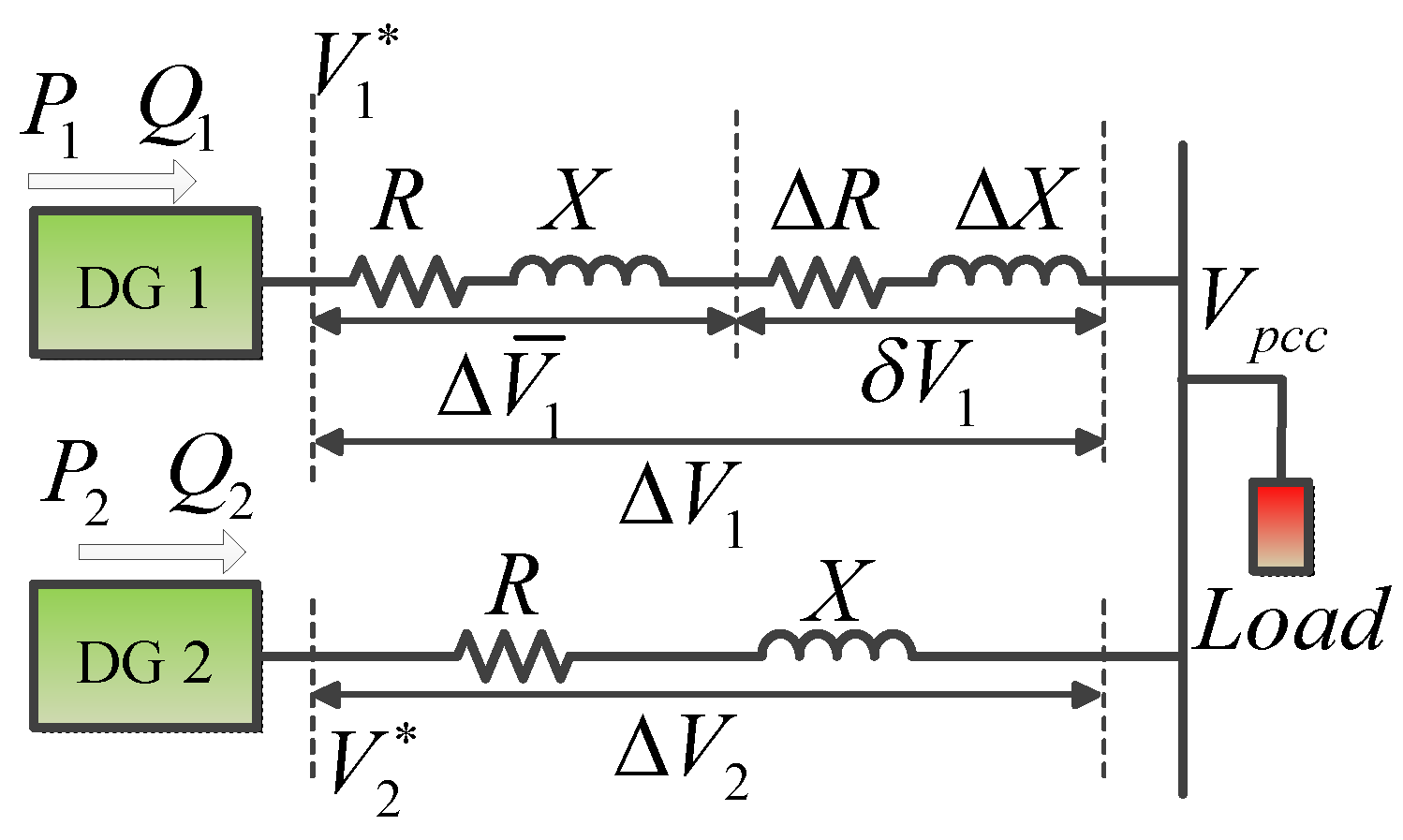
In a MG, the performance of reactive power can be impacted by the feeder impedance mismatch. The impedance installed in between the DG power source and the bus will decide the voltage drop of the feeder, and ultimately impact the reactive power sharing performance. Consider two DGs in a connected MG as shown in Figure 3, where taking the voltage at the point of common coupling (PCC) as the reference, the voltage drop is described by:
V 1 = V p c c + Δ V ¯ 1 + δ V 1
V 1 = V p c c + Δ V 2
where Δ V ¯ 1 ( X Q 1 + R P 1 ) / V i d , δ V 1 = ( Δ X Q 1 + Δ R P 1 ) / V i d , Δ V 2 = ( X Q 2 + R P 2 ) / V i d . Suppose that the first two DGs in Figure 3 have the same power ratings and the active and reactive powers are shared, then Δ V ¯ 1 = Δ V 2 , which indicates that δ V 1 is the voltage drop mismatch in the feeders of the two DGs. The voltage drop mismatch will result in errors in reactive power sharing across different DG units. Hence, one solution to further enhance reactive power sharing performance is to eliminate the voltage drop imbalance term in Equation (25). Considering Equation (3), and adding an adaptive term in the droop coefficient and we have:
V i d ( k i Q + Δ k i Q ) Δ Q i = V p c c + Δ V ¯ 1 + δ V 1
where Δ k i Q = δ V 1 / Δ Q i . It can be seen that by adding the extra term, the term δ V 1 which determines the mismatch in voltage drop can be eliminated from Equation (26), thus the impact of impedance imbalance is diminished.

4.2. General Power Sharing Control Framework

Incorporating the ETCP proposed previously and the adaptive droop coefficient, the general power sharing control framework structure is shown in Figure 4. The typology of DG1, DG2 and DG3 shown in Figure 1 is taken as an example for illustration purpose. In Figure 4, the agent is responsible for establishing between neighboring DGs.
In each agent, the storage device will collect and store the power output of the DG1 and the neighboring DGs in present and historical time instants. In the meantime, the stored power output data of the in-neighbors and out-neighbors of DG1, as well as the present reactive power of DG1 will serve as inputs for ETC Checking to determine the next communication instant. When the ETC is determined, the messenger will sent out a request for the neighboring agents for communication and the messengers in the other agents will execute the communication command to communicate with Agent 1. With the updated information from the other two DGs, the power sharing algorithm will be updated with the adaptive droop gain coefficient. It is worth noticing that the communication between different agents is conducted with fiber-optical network. Hence, time delay caused by information delivery speed can be neglected.

5. Simulation

Simulation is conducted to verify the effectiveness and overall performance of the proposed approach. The MG topology is the same as that in [19] only except that there are 10 DGs in the MG, where the ring type communication network is employed. The reactive power ratings of the DGs range from 1 KVAr to 2.5 KVAr, and the communication frequency with the periodic communication is 400 Hz.

5.1. Case 1: Load Step Change

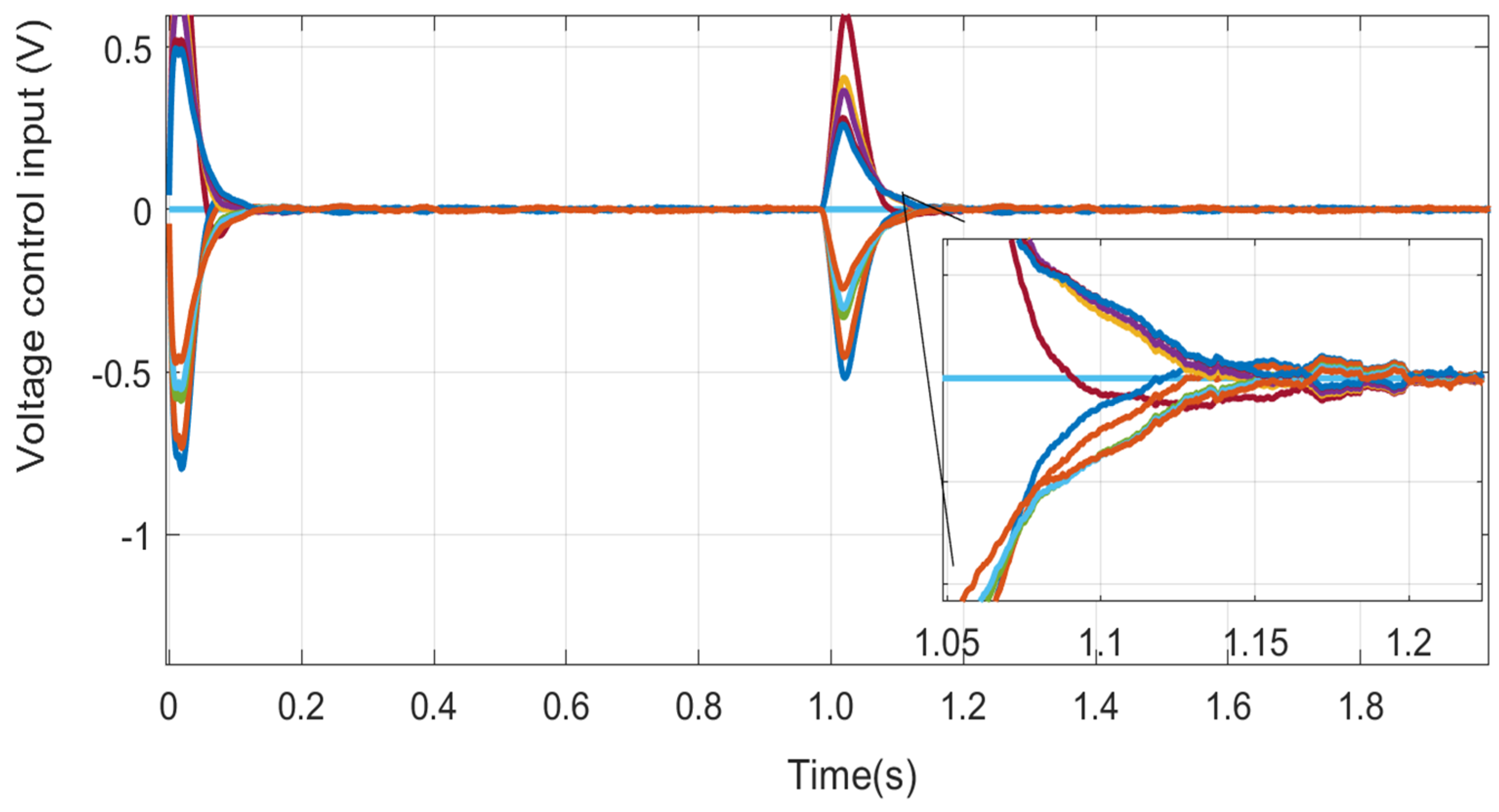
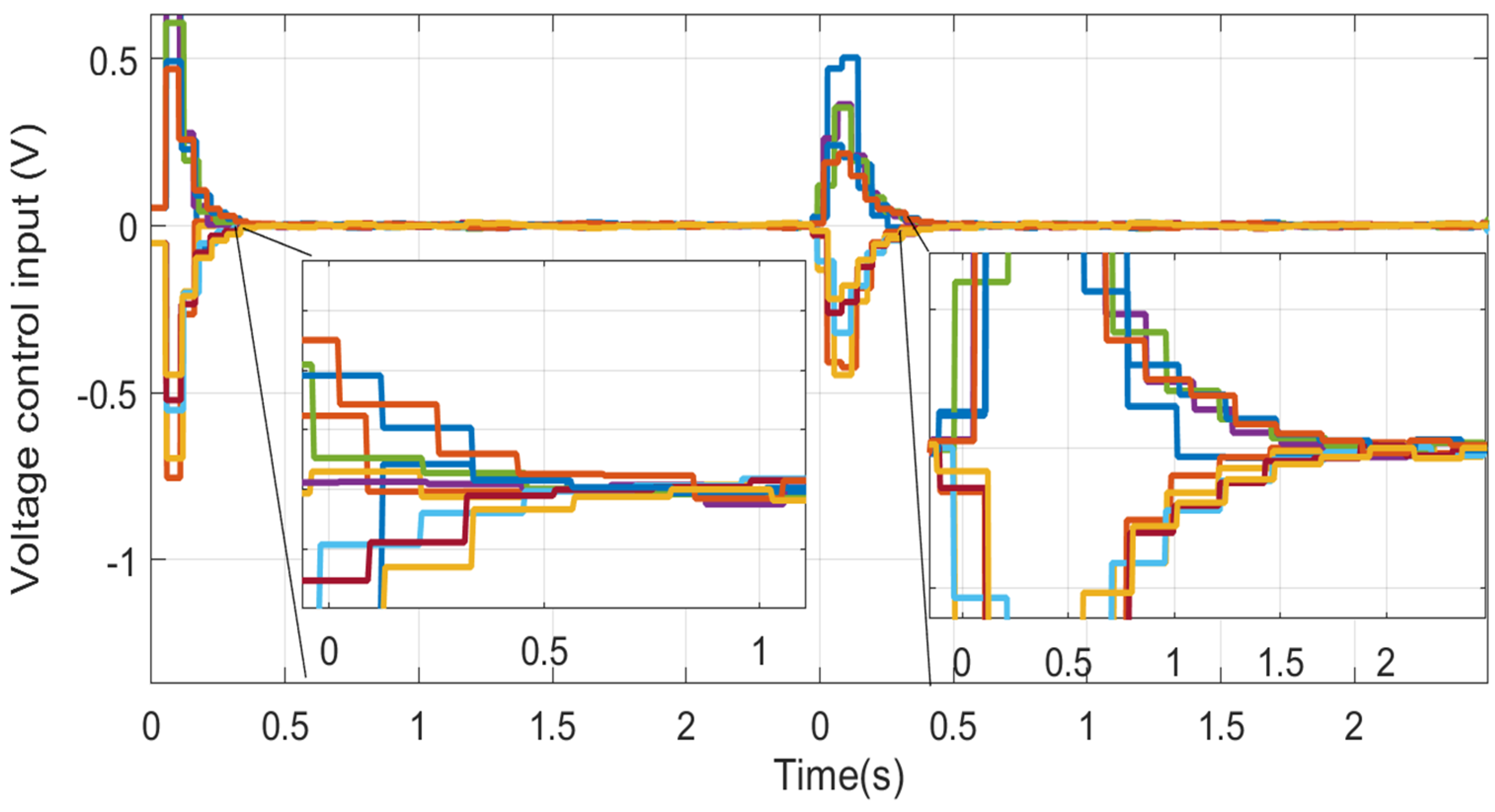
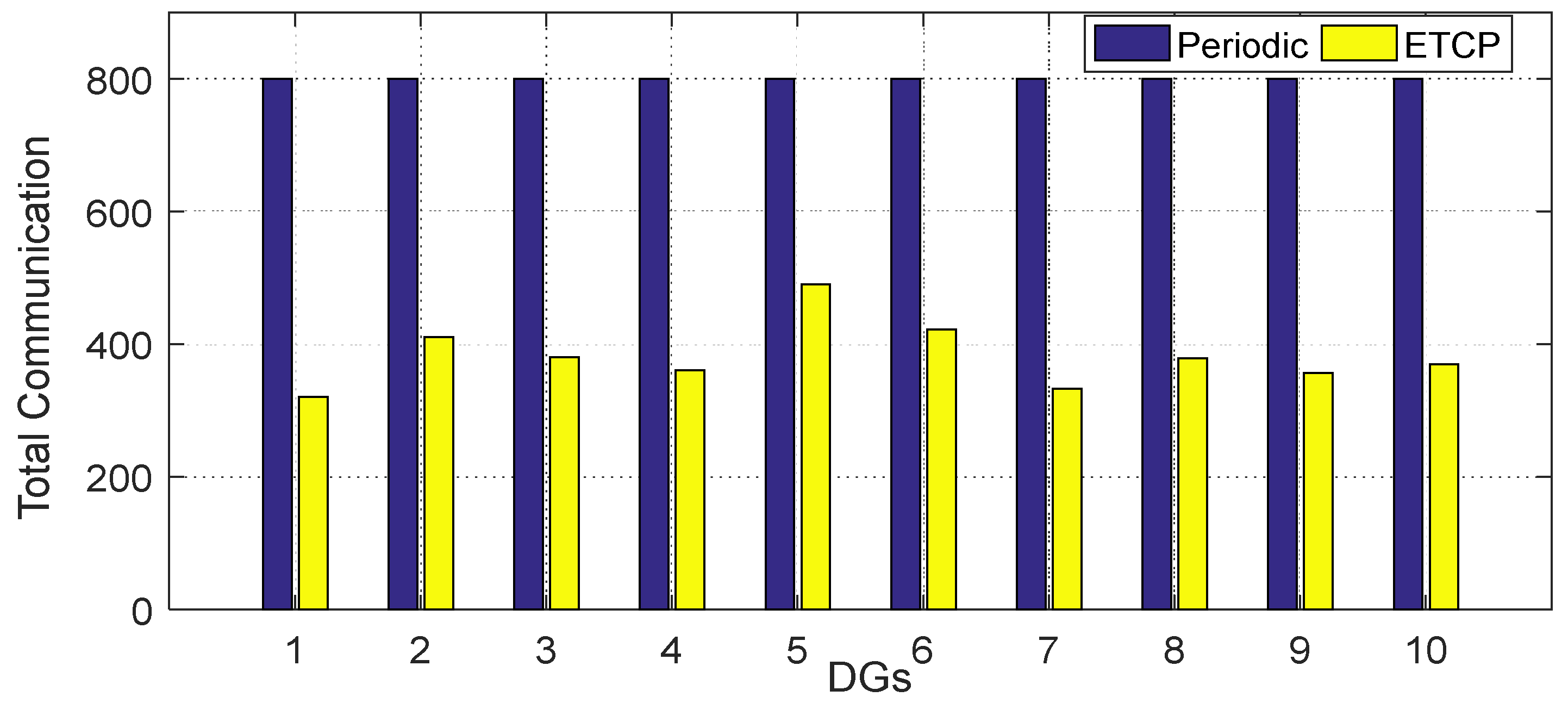
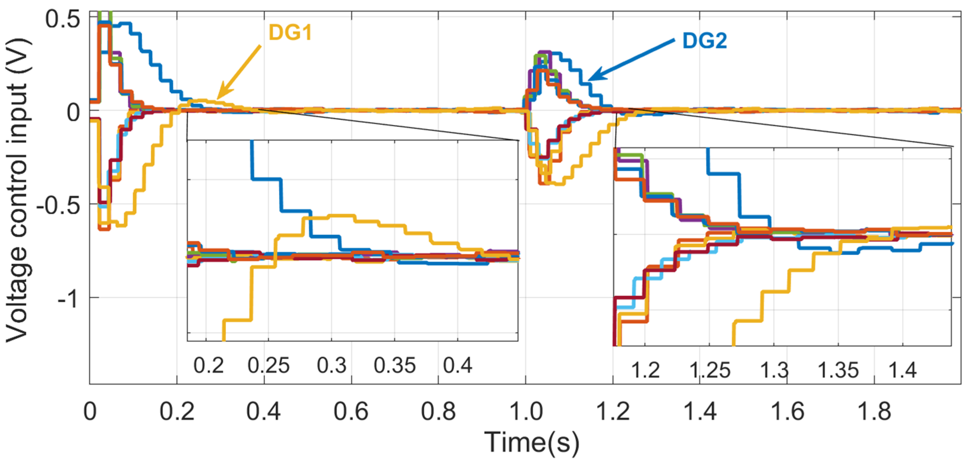
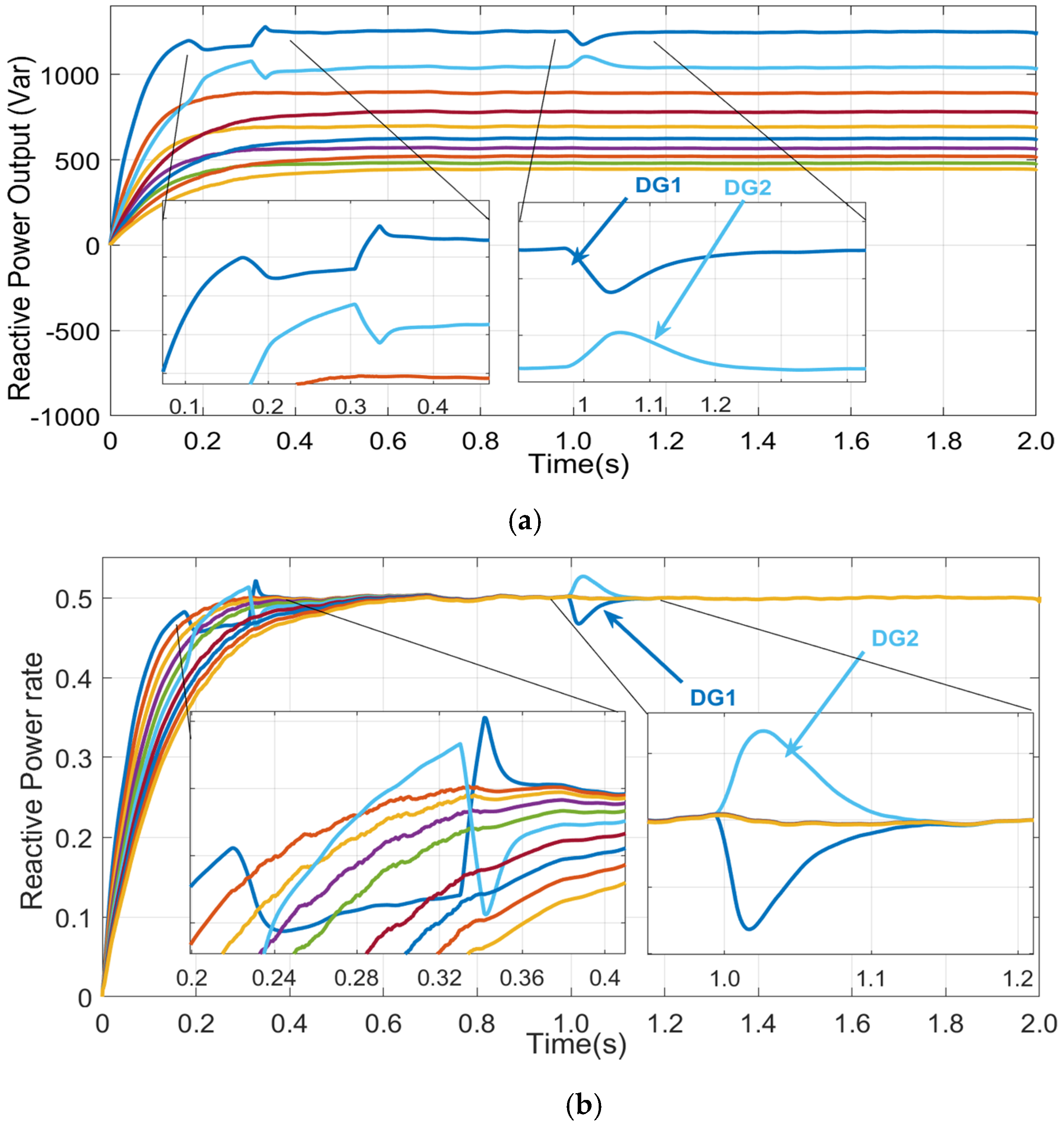
Firstly, it is essential to test the performance of the proposed method under load step change. The DGs are connected with different local loads ranging from 800 VAr to 2 KVAr. To show the improved performance of the proposed approach, the period communication (PC)-based distributed control model in [4] is selected for comparison purpose. Figure 5, Figure 6, Figure 7, Figure 8, Figure 9 and Figure 10 show the simulation results of both methods under load step change. From time t = 0 s to t = 1.0 s , the DGs are connected with 55% of the total rated load; at instant t = 1.0 s , the total load increases to 80% of the rated level. It can be seen from Figure 5 and Figure 6 that both methods show similar behaviors in reactive power sharing, and consensus of the DGs can be achieved in the advent of load step change. Figure 7 and Figure 8 show the control input with PC and ETCP. Obviously, when ETCP is adopted, the control input will be held to the same value in between two consecutive time instants until the ETC is satisfied. In this way, the communication between the neighboring agents is reduced to a certain level, as shown in Figure 9. Figure 10 compares the total numbers of communication with PC and ETCP. It can be figured out that the agents with PC require the same numbers of communication, while the numbers of communication with ETCP is diversified but much less than those of the PC. Hence, the effectiveness of the ETCP in communication reduction and performance maintenance is verified.

5.2. Case 2: Impact of Communication Time Delay

It is necessary to analyze the impact of communication time delay on the performance of the proposed method. It is assumed that time delays happen between agent 1 and agent 2 with delay values: τ = 30 m s , τ = 55 m s and τ = 80 m s . The time delay happens when there is a load step change at time node t = 1.0 s . Simulation results with the three time delays are shown in Figure 11, Figure 12 and Figure 13.
It can be seen from Figure 11 that when the time delay happens, it takes the agents longer time to reach the new consensus state, and the time for convergence increases if the delay time becomes larger. Figure 12 and Figure 13 show the control input with PC and ETCP with time delay τ = 80 m s . Obviously, the control input lasts longer before converging to a stable value if there is time delay.

5.3. Case 3: Communication Link Failure

Communication failure between agents may happen in the operation of MGs, and it has an unexpected impact on the power sharing outcomes of the DGs. Hence, it is necessary to evaluate the impact of communication link failure on the performance of the proposed method. In this case, three types of communication link failure are assumed as shown in Figure 14. The three types of communication failure are typical and they can represent all the possible common failures in the ring topology.
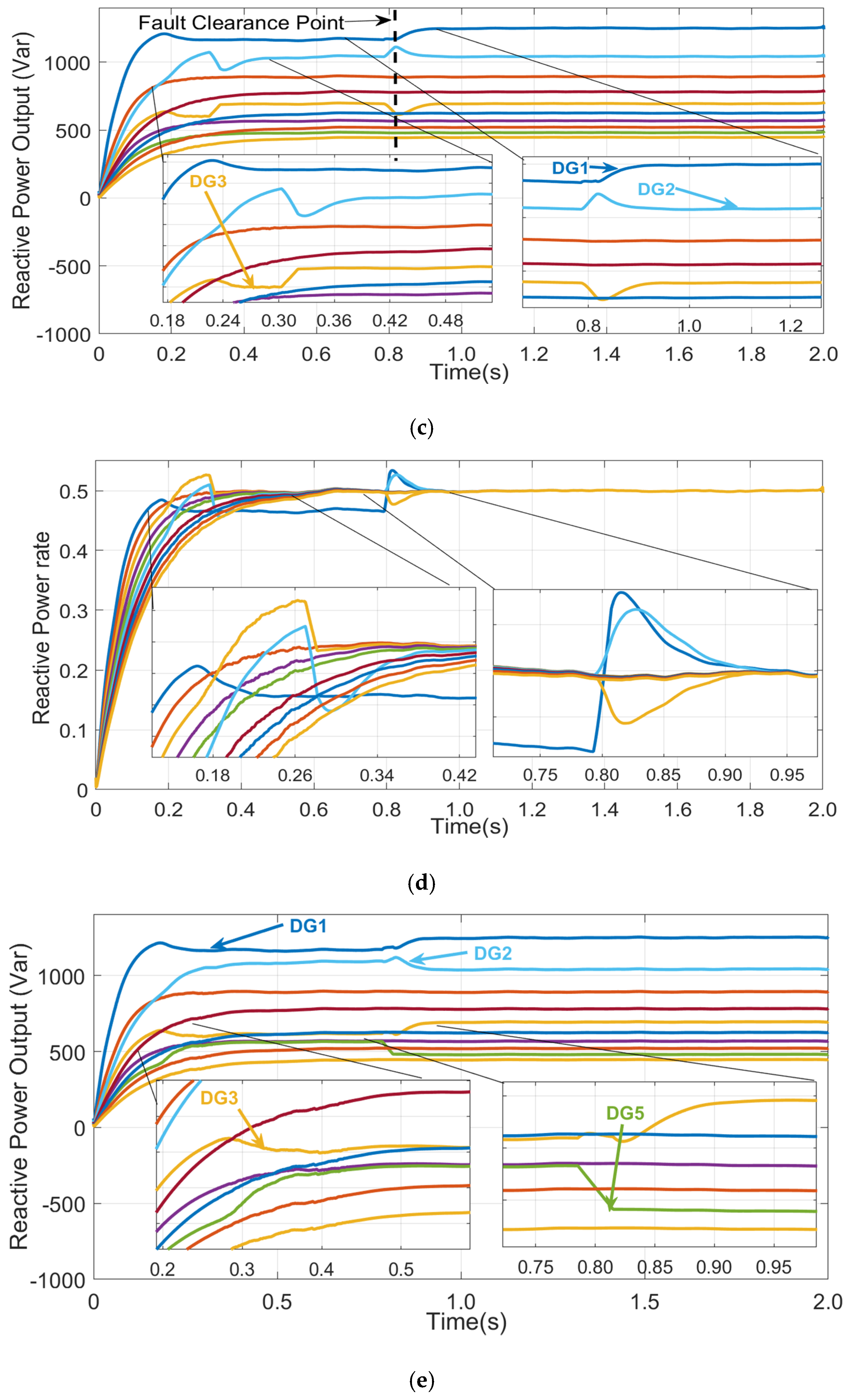
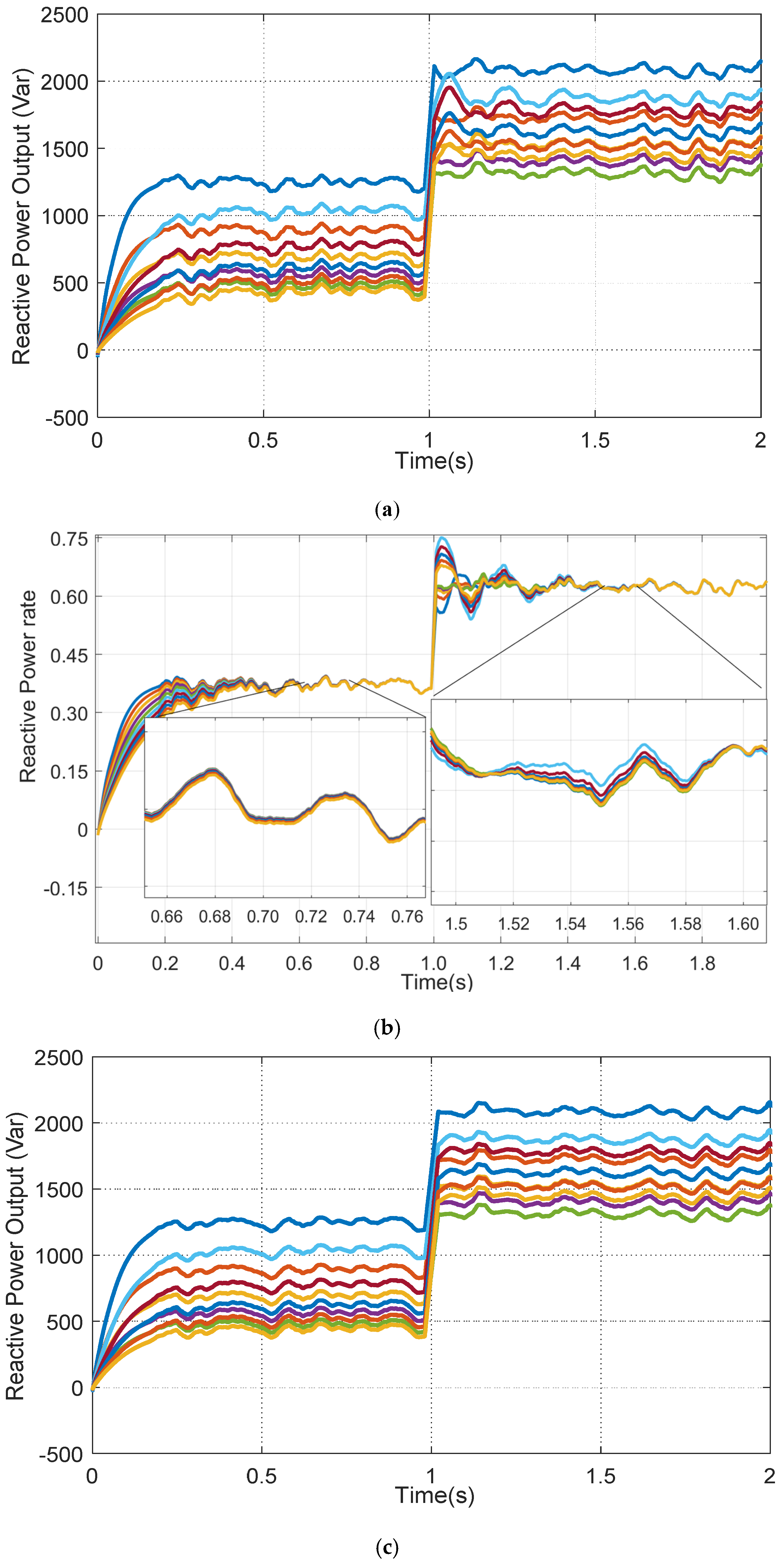
The simulation result under the three communication failures is shown in Figure 15. In Figure 15, the communication failure happens at t = 0.18 s and the communication failure is cleared at t = 0.80 s . When type (a) communication failure happens, only agent 1 and 2 are directly impacted and their reactive power outputs experience minor fluctuation before they reach the consensus state. When the fault is cleared at t = 0.80 s , their power output will again be impacted and they can get back to the consensus state fast. When type (b) failure happens, agent 1 will lose contact with agent 1 and agent 3. Without communication, DG1 will reach an independent state, as shown in Figure 15d. After the fault is cleared, DG1 will get back to the consensus state. When type (c) failure happens, agent 1 and 3 are isolated from the network and they share information with each other. Without communication with the rest of the agents, agent 1 and 3 reach their new state of consensus, as shown in Figure 15f, and they will return to the consensus state of the other agents when the fault is cleared.
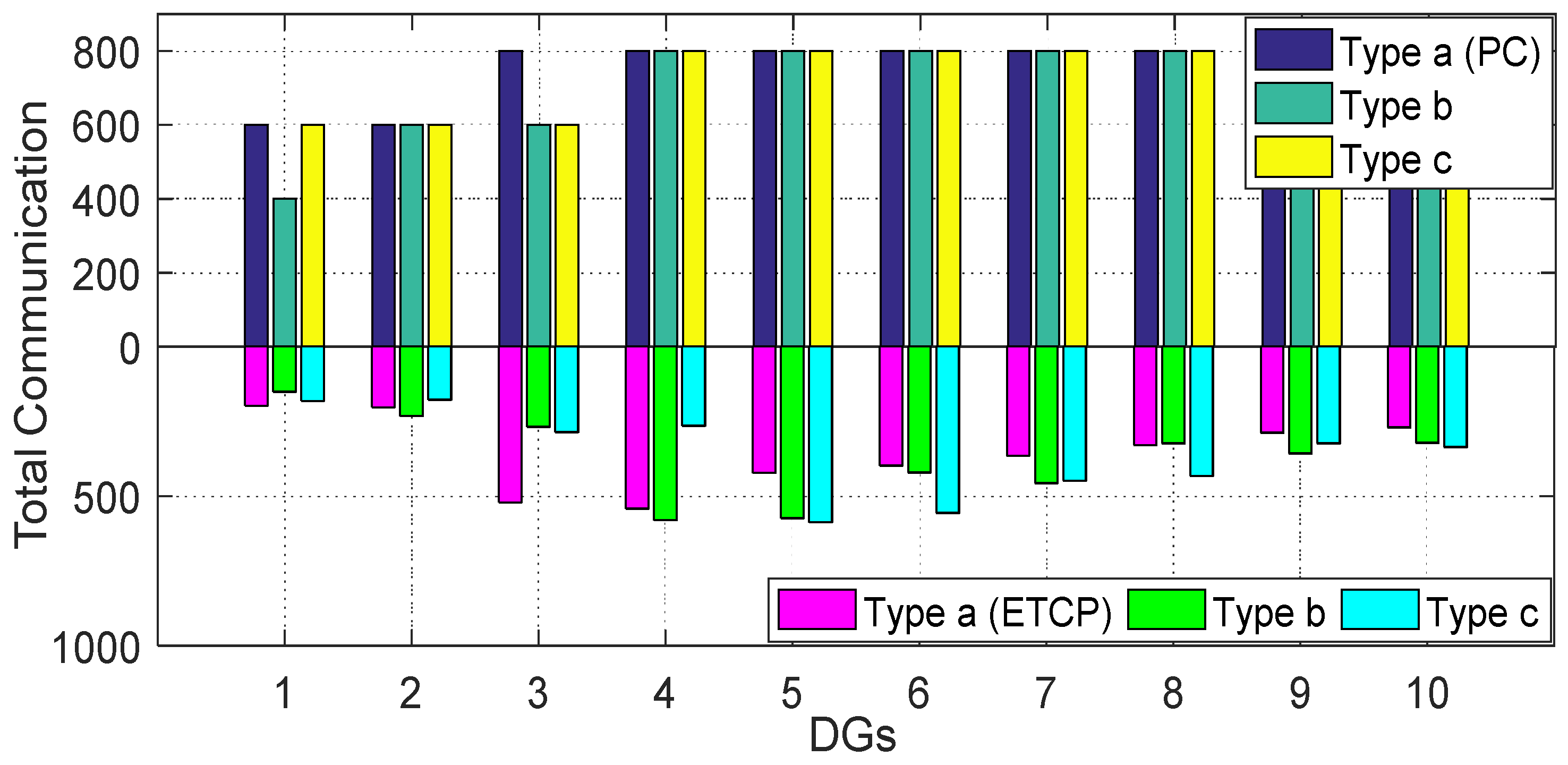
Figure 16 compares the total communication times of 10 DGs with ETCP and PC under three types of communication failure. Obviously, with the ETCP, the communication numbers can be largely reduced.
Moreover, it can be observed in the bottom part of Figure 16 that if the agent is topologically farther from the failure point, it requires less communication with the neighbors, as its performance is less impacted by the failure.

5.4. Case 4: Power Generation Fluctuation

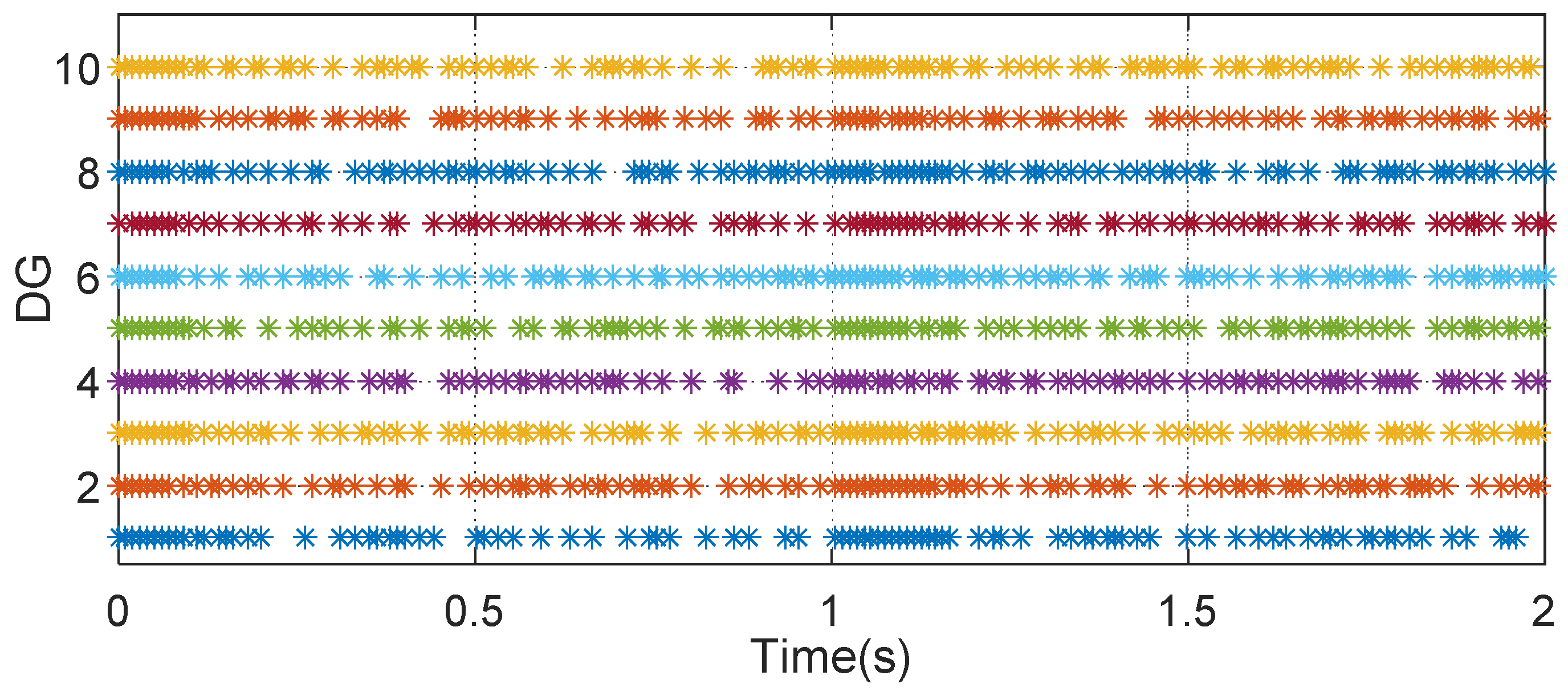
As the power sources of DGs are non-conventional and stochastic, power generation fluctuation is inevitable and it can impact the reactive power control performance since the power sources become less predictable. Thus, it is necessary to test the performance of the proposed method under reactive power generation fluctuation. In this case, the DG source power is replaced by wind energy with the same reactive power level. Figure 17 to Figure 19 shows the simulation results of the proposed method and the PC-based reactive power sharing. Comparing Figure 17a–d, it can be figured out that with the ETCP approach, the DGs can converge to the consensus state in a faster manner. Figure 17e,f show the control input of the two methods. Comparing Figure 17f and Figure 8 or Figure 13, it can be observed that the control input in this case has to be updated at a much higher frequency and the average time for a control signal to be held is largely shortened. This is caused by the fact that the control error is harder to be eliminated and the ETC will be easier fulfilled, as the power generation fluctuates and become less predictable. Figure 18 and Figure 19 present the triggering instant and the total communication numbers, respectively.
Figure 19 shows that although the communication frequency among agents increases, the ETCP approach can still reduce the total communication effort while maintaining the performance.

6. Experimental Verification

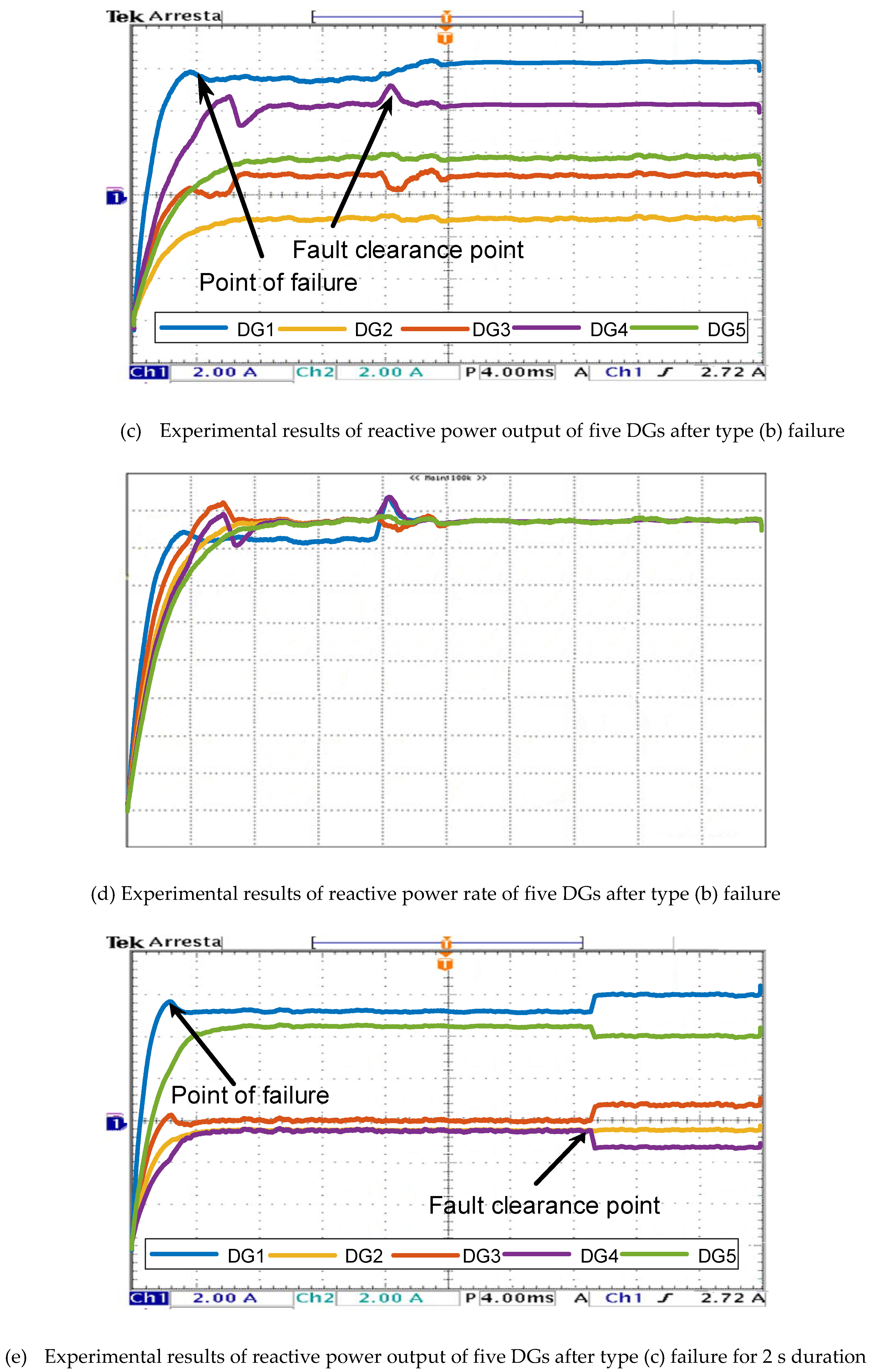
To show the validity of the proposed method in the real environment, experiments are conducted. In this study, the experimental platform consists of five DGs with the same rated power of 20KVA. The system parameters can be found in [19]. The DGs have communication links between them with the ring topology and they are controlled by a central controller, as shown in Figure 20. In this case, we check the validity of the proposed method when the DGs network experiences communication failure as demonstrated in Case 5.3 in the simulation. The type (a), type (b) and type (c) communication failures in Figure 14 are considered in the experimental setting. At time t = 0.2 s , the type (a) and type (b) communication failures are initialized in the communication failure respectively, and the failures are clearly at time t = 1.0 s . The experimental results are shown in Figure 21a,b and Figure 20c,d. Moreover, in order to show how the system reacts toward longer communication failure duration, the type (c) failure is initialized at t = 0.2 s and the failure is cleared at time t = 2.2 s . The corresponding experimental results are shown in Figure 21e,f.
It can be observed from Figure 21a,b that when the type (a) failure happens, the DGs can still reach consensus for power sharing as the communication between five DGs is still linked. From Figure 21c,d, it can be observed that if DG 1 is isolated from the communication link, it cannot reach consensus with the other four DGs, as there is no communication link between DG1 and the other DGs. Nevertheless, after the communication failure is cleared, DG1 can still reach the consensus state for reactive power sharing. Meanwhile, when the type (c) communication failure happens, i.e., two connected DGs are isolated from the communication network, two different consensus states can be achieved, as shown in Figure 21f.

7. Conclusions

This paper proposes an ETCP-based reactive power sharing approach for MGs with the consensus principle. A MAS-based ring network is established to form the communication between DGs. The ETCP aims to reduce the communication between neighboring DGs thus saving resources and enhance system reliability. A novel ETC is proposed to trigger exchange of information and a stability analysis is conducted to prove the existence of equilibrium point and freeness of the Zeno solution. Moreover, an adaptive droop gain is designed to reduce the impact of imbalanced feeder impedance. Four case studies are conducted to verify the effectiveness of the proposed method. The simulation results show that the proposed ETCP approach is capable of reducing the communication effort and maintain the power sharing performance. Moreover, the ETCP approach is adaptive to different operation scenarios by shifting its communication mode.

Author Contributions

Conceptualization, L.X. and P.L.; methodology, L.X.; software, C.W. and S.H.; validation, S.H.; resources: J.W.; writing-original draft preparation, L.X.; writing-review and editing, P.L.; funding acquisition, J.W. All authors have read and agreed to the published version of the manuscript.

Funding

This work was supported by Natural Science Foundation of Chongqing, China, under the Grant No. cstc2019jcyj-zdxmX005.

Conflicts of Interest

The authors declare no conflict of interest in the submission of this paper.

References

  1. Lasseter, R.H. Smart distribution: Coupled microgrids. Proc. IEEE 2011, 99, 1074–1082. [Google Scholar] [CrossRef]
  2. Xiong, L.; Wang, J.; Mi, X.; Khan, M.W. Fractional order sliding mode based direct power control of grid-connected DFIG. IEEE Trans. Power Syst. 2018, 33, 3087–3096. [Google Scholar] [CrossRef]
  3. Olivares, D.E.; Mehrizi-Sani, A.; Etemadi, A.H.; Cañizares, C.A.; Iravani, R.; Kazerani, M.; Hajimiragha, A.H.; Gomis-Bellmunt, O.; Saeedifard, M.; Palma-Behnke, R.; et al. Trends in microgrid control. IEEE Trans. Smart Grid 2014, 5, 1905–1919. [Google Scholar] [CrossRef]
  4. Chen, F.; Chen, M.; Li, Q.; Guerrero, J.M.; Abbott, D. Multiagent-based reactive power sharing and control model for islanded microgrids. IEEE Trans. Sustain. Energy 2016, 7, 1232–1244. [Google Scholar] [CrossRef] [Green Version]
  5. Guo, F.; Wen, C.; Mao, J.; Song, Y.D. Distributed secondary voltage and frequency restoration control of droop-controlled inverter-based microgrids. IEEE Trans. Ind. Electron. 2015, 62, 4355–4364. [Google Scholar] [CrossRef]
  6. Huang, S.; Zhou, B.; Bu, S.; Li, C.; Zhang, C.; Wang, H.; Wang, T. Robust fixed-time sliding mode control for fractional-order nonlinear hydro turbine governing system. Renew. Energy 2019, 139, 1–20. [Google Scholar] [CrossRef]
  7. Rashidirad, N.; Hamzeh, M.; Sheshyekani, K.; Afjei, E. A simplified equivalent model for the analysis of low-frequency stability of multi-bus DC microgrids. IEEE Trans. Smart Grid 2018, 9, 6170–6182. [Google Scholar] [CrossRef]
  8. Xiong, L.; Li, P.; Wang, Z.; Wang, J. Multi-agent based multi objective renewable energy management for diversified community power consumers. Appl. Energy 2020, 259, 1–16. [Google Scholar] [CrossRef]
  9. Davari, M.; Mohamed, Y.A.I. Robust droop and DC-bus voltage control for effective stabilization and power sharing in VSC multiterminal DC grids. IEEE Trans. Power Electron. 2018, 33, 4373–4395. [Google Scholar] [CrossRef]
  10. Zhu, Y.; Fan, Q.; Liu, B.; Wang, T. An enhanced virtual impedance optimization method for reactive power sharing in microgrids. IEEE Trans. Power Electron. 2018, 33, 10390–10402. [Google Scholar] [CrossRef]
  11. Maknouninejad, A.; Qu, Z.; Lewis, F.L.; Davoudi, A. Optimal, nonlinear, and distributed designs of droop controls for DC microgrids. IEEE Trans. Smart Grid 2014, 5, 2508–2516. [Google Scholar] [CrossRef]
  12. Mahmood, H.; Michaelson, D.; Jiang, J. Reactive power sharing in islanded microgrids using adaptive voltage droop control. IEEE Trans. Smart Grid 2015, 6, 3052–3060. [Google Scholar] [CrossRef]
  13. Tah, A.; Das, D. An enhanced droop control method for accurate load sharing and voltage improvement of isolated and interconnected DC microgrids. IEEE Trans. Sustain. Energy 2016, 7, 1194–1204. [Google Scholar] [CrossRef]
  14. Bidram, A.; Davoudi, A.; Lewis, F.L.; Ge, S.S. Distributed adaptive voltage control of inverter-based microgrids. IEEE Trans. Energy Convers. 2014, 29, 862–872. [Google Scholar] [CrossRef]
  15. Guerrero, J.M.; Hang, L.; Uceda, J. Control of distributed uninterruptible power supply systems. IEEE Trans. Ind. Electron. 2008, 55, 2845–2859. [Google Scholar] [CrossRef] [Green Version]
  16. Sun, Q.; Han, R.; Zhang, H.; Zhou, J.; Guerrero, J.M. A multiagent based consensus algorithm for distributed coordinated control of distributed generators in the energy Internet. IEEE Trans. Smart Grid 2015, 6, 3006–3019. [Google Scholar] [CrossRef] [Green Version]
  17. Simpson-Porco, J.W.; Dorfler, F.; Bullo, F. Synchronization and power sharing for droop-controlled inverters in islanded microgrids. Automatica 2013, 49, 2603–2611. [Google Scholar] [CrossRef] [Green Version]
  18. Meng, L.; Dragicevié, T.; Roldán-Pérez, J.; Vasquez, J.C.; Guerrero, J.M. Modeling and sensitivity study of consensus algorithm based distributed hierarchical control for DC microgrids. IEEE Trans. Smart Grid 2016, 7, 1504–1515. [Google Scholar] [CrossRef] [Green Version]
  19. Zhou, J.; Kim, S.; Zhang, H.; Sun, Q.; Han, R. Consensus-based distributed control for accurate reactive, harmonic, and imbalance power sharing in microgrids. IEEE Trans. Smart Grid 2018, 9, 2453–2467. [Google Scholar] [CrossRef] [Green Version]
  20. Olfati-Saber, R.; Fax, J.A.; Murray, R.M. Consensus and cooperation in networked multi-agent systems. IEEE Proc. 2017, 95, 215–233. [Google Scholar] [CrossRef] [Green Version]
  21. Hamad, A.A.; Azzouz, M.A.; El-Saadany, E.F. Multiagent supervisory control for power management in DC microgrids. IEEE Trans. Smart Grid 2016, 7, 1057–1067. [Google Scholar] [CrossRef]
  22. Wang, X.; Lemmon, M.D. Event-triggering in distributed networked control systems. IEEE Trans. Autom. Control 2011, 56, 586–601. [Google Scholar] [CrossRef] [Green Version]
  23. Xiong, L.; Li, P.; Wu, F.; Ma, M.; Khan, M.W.; Wang, J. A coordinated high-order sliding mode control of DFIG wind turbine for power optimization and grid synchronization. Int. J. Electr. Power Energy Syst. 2019, 105, 679–689. [Google Scholar] [CrossRef]
  24. Seyboth, G.S.; Dimarogonas, D.V.; Johansson, K.H. Event-based broadcasting for multi-agent average consensus. Automatica 2013, 49, 245–252. [Google Scholar] [CrossRef]
  25. Guerrero, J.M.; Loh, P.C.; Chandorkar, M.; Lee, T. Advanced control architectures for intelligent microgrids—Part I: Decentralized and hierarchical control. IEEE Trans. Ind. Electron. 2013, 60, 1254–1262. [Google Scholar] [CrossRef] [Green Version]
  26. Schiffer, J.; Seel, T.; Raisch, J.; Sezi, T. Voltage stability and reactive power sharing in inverter-based microgrids with consensus-based distributed voltage control. IEEE Trans. Control Syst. Technol. 2016, 24, 96–109. [Google Scholar] [CrossRef] [Green Version]
  27. Schiffer, J.; Ortega, R.; Astolfi, A.; Raisch, J.; Sezi, T. Conditions for stability of droop-controlled inverter-based microgrids. Automatica 2014, 50, 2457–2469. [Google Scholar] [CrossRef] [Green Version]
  28. Horn, R.A.; Johnson, C.R. Topics in Matrix Analysis; Cambridge University Press: New York, NY, USA, 1991. [Google Scholar]
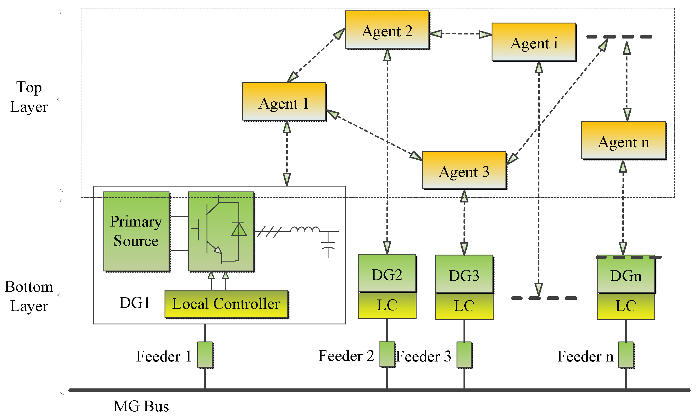
Figure 1. MAS-based islanded MG model.
Energies 13 01152 g001
Figure 2. Control architecture for the i-th agent.
Energies 13 01152 g002
Figure 3. Structure of two DG units connected to a bus.
Energies 13 01152 g003
Figure 4. General power sharing control framework structure.
Energies 13 01152 g004
Figure 5. Reactive power output of 10 DGs with periodic communication.
Energies 13 01152 g005
Figure 6. Reactive power output of 10 DGs with ETCP.
Energies 13 01152 g006
Figure 7. Control input with periodic communication.
Energies 13 01152 g007
Figure 8. Control input with ETCP.
Energies 13 01152 g008
Figure 9. Triggering instant of 10 DGs with ETCP.
Energies 13 01152 g009
Figure 10. Total communication of ETCP and periodic communication.
Energies 13 01152 g010
Figure 11. Simulation results for reactive power output of 10 DGs with time delays: (a,b) for time delay τ = 30 m s ; (c,d) for time delay τ = 55 m s ; (e,f) for time delay τ = 80 m s .
Energies 13 01152 g011
Figure 12. Control input with periodic communication with time delay τ = 80 m s .
Energies 13 01152 g012
Figure 13. Control input with ETCP with time delay τ = 80 m s .
Energies 13 01152 g013
Figure 14. Three communication failure topologies.
Energies 13 01152 g014
Figure 15. Simulation results for reactive power output with three types of communication failure: (a,b) for type (a) failure; (c,d) for type (b) failure; (e,f) for type (c) failure.
Energies 13 01152 g015aEnergies 13 01152 g015bEnergies 13 01152 g015c
Figure 16. Total communication numbers of ETCP and PC under three types of communication failure.
Energies 13 01152 g016
Figure 17. Simulation results for reactive power output with power generation fluctuation: (a,b) with periodic communication; (c,d) with ETCP; (e) control input of periodic communication; (f) control input of ETCP.
Energies 13 01152 g017aEnergies 13 01152 g017b
Figure 18. Triggering instant with ETCP under power generation fluctuation.
Energies 13 01152 g018
Figure 19. Total communication numbers of ETCP and PC under power generation fluctuation.
Energies 13 01152 g019
Figure 20. Communication networks and three types of failures of five DGs in the experiment.
Energies 13 01152 g020
Figure 21. Experimental results of three kinds of communication failures with different durations.
Energies 13 01152 g021aEnergies 13 01152 g021bEnergies 13 01152 g021c