Article

Investigating the System Behaviors of a 10 kW Organic Rankine Cycle (ORC) Prototype Using Plunger Pump and Centrifugal Pump

1
School of Energy and Power Engineering, Jiangsu University, Zhenjiang 212013, China
2
Department of Mechanical Engineering, National Taipei University of Technology, Taipei 350118, Taiwan
3
Institute for Energy Research, Jiangsu University, Zhenjiang 212013, China
4
Department of Refrigeration, Air Conditioning and Energy Engineering, National Chin-Yi University of Technology, Taipei 350118, Taiwan
5
Department of Agricultural Engineering, Bahauddin Zakariya University, Bosan Road, Multan 60800, Pakistan
*
Authors to whom correspondence should be addressed.
Energies 2020, 13(5), 1141; https://doi.org/10.3390/en13051141
Submission received: 31 January 2020 / Revised: 19 February 2020 / Accepted: 20 February 2020 / Published: 3 March 2020
(This article belongs to the Special Issue Geothermal Energy Utilization and Technologies 2020)

Abstract

:
Based on a 10-kW organic Rankine cycle (ORC) experimental prototype, the system behaviors using a plunger pump and centrifugal pump have been investigated. The heat input is in the range of 45 kW to 82 kW. The temperature utilization rate is defined to appraise heat source utilization. The detailed components’ behaviors with the varying heat input are discussed, while the system generating efficiency is examined. The exergy destruction for the four components is addressed finally. Results indicated that the centrifugal pump owns a relatively higher mass flow rate and pump isentropic efficiency, but more power consumption than the plunger pump. The evaporator pressure drops are in the range of 0.45–0.65 bar, demonstrating that the pressure drop should be considered for the ORC simulation. The electrical power has a small difference using a plunger pump and a centrifugal pump, indicating that the electric power is insensitive on the pump types. The system generating efficiency for the plunger pump is approximately 3.63%, which is 12.51% higher than that of the centrifugal pump. The exergy destruction for the evaporator, expander, and condenser is almost 30%, indicating that enhancing the temperature matching between the system and the heat (cold) source is a way to improve the system performance.

1. Introduction

The issues of energy high-speed consumption and safe supply have aroused widespread concern in society. In order to effectively solve the energy problem, countries around the world have proposed measures that focus on both energy development and conservation. According to statistics, 50% of the energy used by humans is directly emitted by low-temperature waste heat. If this energy can be used, it will not only solve some energy problems but also reduce environmental pollution. Among much of the low-grade thermal energy conversion and utilization technologies, the organic Rankine cycle is extensively applied on account of its wide temperature range and moderate power [1,2,3]. In addition, the organic Rankine cycle is often used in conjunction with other systems to achieve higher efficiency. Peris et al. [4] were interested in using ORC for combined heat and power (CHP) applications, and Capata et al. [5] recovered vehicle waste heat with small-scale ORC. In addition, solar energy, wind energy, and ocean temperature difference energy are of particular interest in small-scale ORC systems [6,7,8]. Therefore, extensive research studies have been conducted on the ORC.
For the industrial ORC prototype, the back work ratio is as high as 25%, indicating that improving the pump performance is a key for ORC commercial application. Numerous studies devoted main efforts on the pump improvement, including piston pumps, gear pumps, and centrifugal pumps. The vane pump delivers energy by the impeller, while the positive displacement pump is dependent on the periodic variation of the volume. Mathias et al. [9] conducted a comparison between the piston pump and gear pump, representing that the piston pump was preferred for the ORC system. Lei et al. [10] tested an ORC system using a roto-jet pump, stating that the pump efficiency of 11–23% was obtained. Bianchi et al. [11] conducted a test on an ORC system using a sliding vane pump, reporting that the shaft power has a significant influence on mass flow rate and pressure. Villani et al. [12] proposed two different ORC systems combined with the heavy diesel engines. One is that the pump and the expander are connected to achieve a fixed speed, and the other is that the pump and expander are separated, the pump optimal speed and expander optimal speed are selected by adjusting parameters. Zeleny et al. [13] applied a gear pump on the ORC system to evaluate the pump mechanical losses. Xu et al. [14] tested the operation characteristics of a piston pump on an ORC system, demonstrating that the low pump frequency was applicable to all expander torques. Carraro et al. [15] integrated a multi-diaphragm positive displacement pump into a 4-kW experimental prototype and found that the pump global efficiency was about 45–48%. Bianchi et al. [16] changed the pump speed to measure the performance of the pump and the overall system in a micro-ORC and found that the pump has a back-work ratio of 50–75% and causes a lot of power consumption. Therefore, special attention should be paid to the design of the pump in micro-ORC. Zhang et al. [17] experimentally studied the change in pump characteristics with evaporation and condensation temperatures. The pump consumption decreases with increasing condensation temperature and presents a non-linear relationship with increasing evaporation temperature. Xi et al. [18] experimentally tested the transient process for the sudden stop of the working fluid pumps in the ORC and regenerative ORC (RORC) systems and found that the expander showed good performance if the pumps were closed when the working fluid was overcharged. Abam et al. [19] analyzed the exergy performance for each component of the four different ORCs and showed that the exergy destruction of evaporators was the largest and that of the pumps was the smallest. Aleksandra et al. [20] integrated that the use of different refrigerants can produce different pump work. Wu et al. [21] utilized a booster pump instead of a common working pump to optimize system characteristics. Meng et al. [22] investigated the performance of the centrifugal pump applied to the engine exhaust recovery ORC device and found that the total efficiency of the pump was 15–65.7%. In addition, Yang et al. [23] and Sun et al. [24] compared a variety of pumps that can be applied to the ORC in order to find the most suitable pump for ORC systems, indicating that the hydraulic diaphragm metering pump was suitable for low heat capacity, whereas the multistage centrifugal pump was preferred for higher heat capacity. Feng et al. [25,26,27] experimentally compared the system behaviors on a 3kW ORC between pure working fluids and mixture working fluids using a scroll expander. In addition, when the working fluids are condensed in a condenser, the working fluids’ temperature and pressure decrease, resulting in the working fluid pump cavitation. Cavitation affects the stability of the system, resulting in a decrease of system efficiency. D’amico et al. [28] introduced the thermodynamic model of a piston pump in the ORC and proposed the prediction of available head margin to avoid cavitation. Liu et al. [29] found that cavitation can occur when the working fluid was insufficient and proposed overcharging working fluid to avoid cavitation. Yang et al. [30] stated that a subcooling of 20 °C was needed to prevent the cavitation of the piston pump. Pei et al. [31] emphasized the use of a bypass tube to balance the pressure of the pump and the tank to solve the cavitation. Galindoe et al. [32] and Dumont et al. [33] used a liquid sub-cooler to prohibit the cavitation.
To lessen the influence of the pump on the ORC property, a novel concept was proposed—pumpless ORC. Gao et al. [34] raised the gravity-type pumpless ORC to ensure the stability and continuity of the system shaft power output. Bao et al. [35] believed that an ORC system without a pump can achieve a more compact and efficient arrangement, which can improve the system’s net efficiency. Jiang et al. [36] raised a cascade cycle of power and refrigeration, applying the pumpless ORC to the upper cycle and the adsorption refrigeration cycle to the lower cycle. Within the range of experimental parameters, the maximum power is 232 W and the maximum cooling capacity is 4.94 kW.
As mentioned above, it is evident that several experimental investigations using different pumps have been performed. However, limited studies fulfilled the work on the experimental comparison on an ORC operation characteristic using different pumps. Simultaneously, micro- ORC is still in infancy, and more effort should be focused on the components’ design and test. For the micro-ORC prototype, the considerably low efficiency of the pump may heavily affect the overall performance. Therefore, comparing the operation characteristics of small-scale ORC prototypes using different pumps is certainly of great interest. In the present study, a 10 kW R245fa-based ORC experimental prototype is used to study the operation characteristics. A plunger pump and centrifugal pump are adopted, which were widely used in previous experimental tests. The basic operation characteristics for the plunger pump and centrifugal pump are first analyzed. The components’ behaviors are addressed, and the overall performance is examined.

2. Experimental Setup Description

2.1. System Design and Operating Method

A 10 kW ORC test platform is adopted. Figure 1 displays a schematic diagram of the experimental bench, and Figure 2 presents the pictures of the experimental equipment. To provide a simulated heat source, diathermic oil is adopted and heated by an electric heater. An electric heater has twelve electric heating rods, and each rod has a capacity of 10 kW. The heating rods are connected in series with an SCR power regulator to adjust the input electric. The heat source temperature is from 85–105 °C and each variation increases by about 5 °C. The heat input is in the range of 45–85 kW. The evaporator and condenser are both plate heat exchangers and the specific parameters for the heat exchangers are listed in Table 1.
A centrifugal pump and a plunger pump are adopted in this experimental prototype. The mass flow rates are adjusted by the rotating speed of the pump and the pump rotating speed is controlled by a frequency converter. Meanwhile, the pump raises the refrigerant to reasonable working pressure and the refrigerant enters the evaporator to absorb heat. R245fa is chosen as the refrigerant because of its good thermodynamics and economic characteristics. The scroll expander is adopted, which is improved by a scroll air compressor that is operating in reverse. The product of the system is consumed by the electrical resistance and capacitance, which determines the expander speed. The speed of the expander is measured at 2500–2900rpm and the expander specifications are listed in Table 2. The steam refrigerant absorbed heat enters the expander which exports power. In Figure 2, the scroll expander is encapsulated with a generator, and the shaft power is hard to measure. Therefore, the expander shaft power is expressed by the mass flow rates and expander enthalpy difference. Mass flow rates are converted from volume flow rates directly measured by the flowmeter. The enthalpy difference is determined by checking the REFPROP(a software that can check physical properties) according to the temperature and pressure at both ends of the expander. An inductive generator is used as the power output device.
A 3% lubricating oil is added in the expander to avoid the leakages and reduce the friction losses in the expander. In addition, the compatibility of the lubricating oil and R245fa is tested at first. After the expansion, the gaseous refrigerant enters the condenser and transfers the residual heat to the cooling water. The mass flow rate of cooling water is 4m/s, which is regulated by the cooling pump frequency. To better ascertain the effect of the pump on the system behavior, a plunger pump and centrifugal pump are tested and compared in this study.

2.2. Plunger Pump and Centrifugal Pump

The plunger pump has a high volume ratio, small flow rate, good characteristic curve, and low cost. It sucks and discharges the working fluid through the reciprocating motion of the plunger. The maximum flow rate of the reciprocating plunger pump is 15.5 L/min with the maximum pressure of 20 bar.
The centrifugal pump has a small area, less material consumption, less manufacturing and installation costs, and can run at high speeds. The centrifugal pump is driven by centrifugal force. The liquid is pumped out from the center to the periphery along the blade flow path and is sent to the discharge pipe through the volute. The centrifugal pump has a maximum flow rate of 36.7 L/min and the delivery pressure of 25 bar. More detailed information about the pumps is displayed in Table 3.

3. Measuring Device and Thermodynamic Analysis

The detailed operation parameters are measured, including temperature, pressure, and mass flow rate. A vortex flowmeter placed at the pump outlet is used to measure volume flow rates, and then the volume flow rates are converted into mass flow rates, with the detailed location shown in Figure 1. The heat source temperature for both pump experiments was 85–110 °C. The system performance can be obtained based on the measured operation parameters, while an uncertainty analysis is conducted [37].
Δ Y = i ( Y X i ) 2 Δ X i 2
where X and Δ Y are the independent variable and uncertainty, respectively. Table 4 lists the measuring devices and the uncertainties for system parameters.
Figure 3 shows the T-s diagram of the ORC system, the expander isentropic efficiency is calculated based on the ideal expansion process and actual expansion process. The expander isentropic efficiency ( η is , exp ) and pressure difference ( Δ P ) can be calculated as follows:
η is , exp = h 1 h 2 h 1 h 2 s
Δ P = P 1 P 2
where h 1 and p 1 represent the enthalpy and pressure of the expander inlet, and h 2 , p 2 and h 2 s represent the enthalpy, pressure and isentropic enthalpy of the expander outlet.
The condenser heat transfer rate ( Q c o n d ), the logarithmic mean temperature difference (LMTD) ( Δ T c o n d ), heat transfer coefficient ( U c o n d ) and pressure drop( Δ P cond ) can be calculated as follows:
Q cond = m ( h 2 h 5 )
Δ T cond = Δ T max Δ T min ln Δ T max Δ T min = ( T 13 T 5 ) ( T 16 T 2 ) ln T 13 T 5 T 16 T 2
U cond = Q cond Δ T cond A
Δ P cond = P 2 P 5
where h5 is the outlet enthalpy of the condenser; Δ T max and Δ T min are the maximum and minimum temperature difference at the condenser, respectively; and A represents the surface area of the heat exchanger.
The pump isentropic efficiency is calculated by the actual compression process and the ideal compression process. The pump shaft power ( W sh , pump ) and isentropic efficiency ( η is , pump ) are expressed as:
W sh , pump = m ( h 6 h 5 )
η is , pump = h 5 s h 5 h 6 h 5
where h5s and h6 denote the pump outlet enthalpy and isentropic enthalpy.
Similarly, the evaporator heat transfer rate ( Q eva ), LMTD ( Δ T eva ), heat transfer coefficient ( U eva ) and pressure drop ( Δ P eva ) can be expressed as:
Q eva = m ( h 1 h 6 )
Δ T eva = Δ T max Δ T min ln Δ T max Δ T min = ( T 12 T 6 ) ( T 9 T 1 ) ln T 12 T 6 T 9 T 1
U eva = Q eva Δ T eva A
Δ P eva = P 1 P 6
To better understand the heat source utilization, the temperature utilization rate of the heat source ( θ ) is proposed [38]. Assuming that the lowest heat source temperature can reach 60 °C (333.15 K), the denominator of temperature utilization rate θ indicates the heat that the system can use. The numerator denotes the actual heat used by the ORC system. So θ can be expressed as:
θ = ( T H , in T H , out ) / ( T H , in 333.15 )
The generating efficiency can be expressed as:
η ele = W ele , exp W ele , pump Q eva
where W ele , exp and W ele , pump represent the electrical power and pump consumption power.
The exergy destruction of the four components including the pump ( E d , pump ), evaporator ( E d , eva ), expander ( E d , exp ) and condenser ( E d , cond ) can be calculated as follows:
E d , pump = T 0 m ( s 6 s 5 )
E d , eva = T 0 m [ ( s 1 s 6 ) 2 ( h 1 h 6 ) / ( T 9 + T 12 ) ]
E d , exp = T 0 m ( s 2 s 1 )
E d , con = T 0 m [ ( s 5 s 2 ) 2 ( h 5 h 2 ) / ( T 13 + T 16 ) ]

4. Results and Discussion

To better compare the cycle behaviors of a 10-kW experimental prototype using two different pumps, the system operation parameters at different heat inputs are collected. The heat input for the plunger pump and centrifugal pump are in the range of 44.74–76.48 kW and 45.61–81.35 kW, respectively. The basic operating parameters using the plunger pump and centrifugal pump are displayed in Section 4.1. The detailed components’ behaviors are described in Section 4.2, while the overall cycle characteristics, including system generating efficiency and exergy destruction are expressed in Section 4.3.

4.1. Basic Operating Parameters

In particular, the present data is collected at different time periods. It is difficult to keep the ambient temperature constant because of the fluctuating ambient conditions. However, the environment temperature has a great influence on the condensation process, so it has a strong guiding significance for explaining many basic operating parameters of ORC, such as pump inlet temperature and shaft work, etc. The environment temperatures for the ORC system using the plunger pump and centrifugal pump are listed in Table 5 and Table 6, respectively. The environment temperature for the plunger pump is approaching 23 °C, which is 4 °C higher than that of the centrifugal pump. Figure 4 illustrates the relationship between mass flow rate and heat input using the plunger pump and centrifugal pump. When the heat input keeps rising, more working fluids are needed to absorb the heat from the evaporator. It also can be found that the centrifugal pump has a slightly higher mass flow rate than the plunger pump for the same heat input, which may be contributed to the centrifugal pump having the higher rotating speed and greater flow per revolution. The mass flow rate for the centrifugal pump is from 0.17 to 0.31 kg/s, which is 6.7% higher than that of the plunger pump.
Figure 5 shows details of the temperature and pressure for the pump inlet and outlet with heat input using the plunger pump and centrifugal pump. In Figure 5a, the centrifugal pump inlet temperature and pressure have no obvious variation with the heat input. However, the plunger pump inlet temperature appears to suddenly decrease when the heat inputs exceed 66.53 kW, owing to the fluctuating environmental temperature. The environment temperature decreases slightly for heat inputs over 66.53 kW, resulting in a decrease of cooling water temperature and the pump inlet temperature. In Figure 5b, the pump outlet temperature has a similar trend to the state at the pump inlet, whereas the pump outlet pressure shows a sharp increase with the heat input. Because of the difficulty in repeating tests with similar environmental temperatures, the non-dimensional operating parameter (pump pressure ratio) is chosen to compare the characteristic of the two pumps, which is shown in Figure 5c. The centrifugal pump pressure ratio is much higher than the plunger pump. The pump outlet pressure for the plunger pump is in the range of 7.58–10.87 bar, which is 0.3 bar higher than that of the centrifugal pump ranging from 7.29 bar to 10.84 bar.
Figure 6 presents the comparison of expander inlet and outlet temperatures and pressure with heat input using the plunger pump and centrifugal pump. In Figure 6a, the expander inlet temperature and pressure increase monotonically with heat input. The expander inlet temperature of the plunger pump rises from 82.20 °C to 97.74 °C for heat inputs increasing from 45 kW to 85 kW, with the corresponding expander inlet pressure ranging from 7.13 bar to 10.23 bar. Meanwhile, the plunger pump demonstrates a higher expander inlet pressure and temperature than the centrifugal pump. The expander outlet pressure and temperature keep rising in Figure 6b, which is similar to that at the expander inlet. Similarly, in order to more clearly compare the features of the expander using the two pump systems, the pressure ratio for the expander is shown in Figure 6c. The expander pressure ratio in the system using the centrifugal pump is more favorable than that using the plunger pump because the centrifugal pump can provide higher pressure to the system.

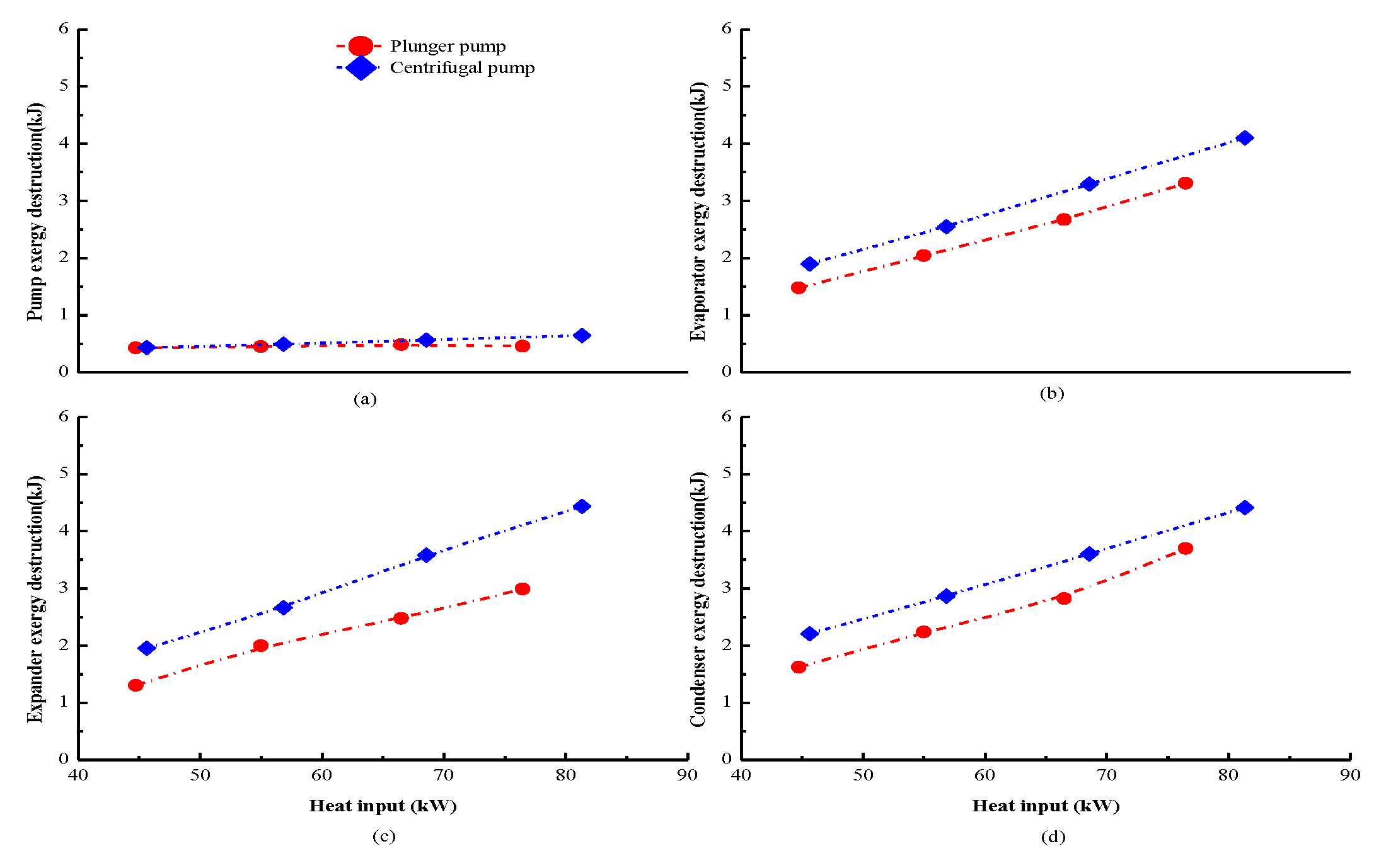
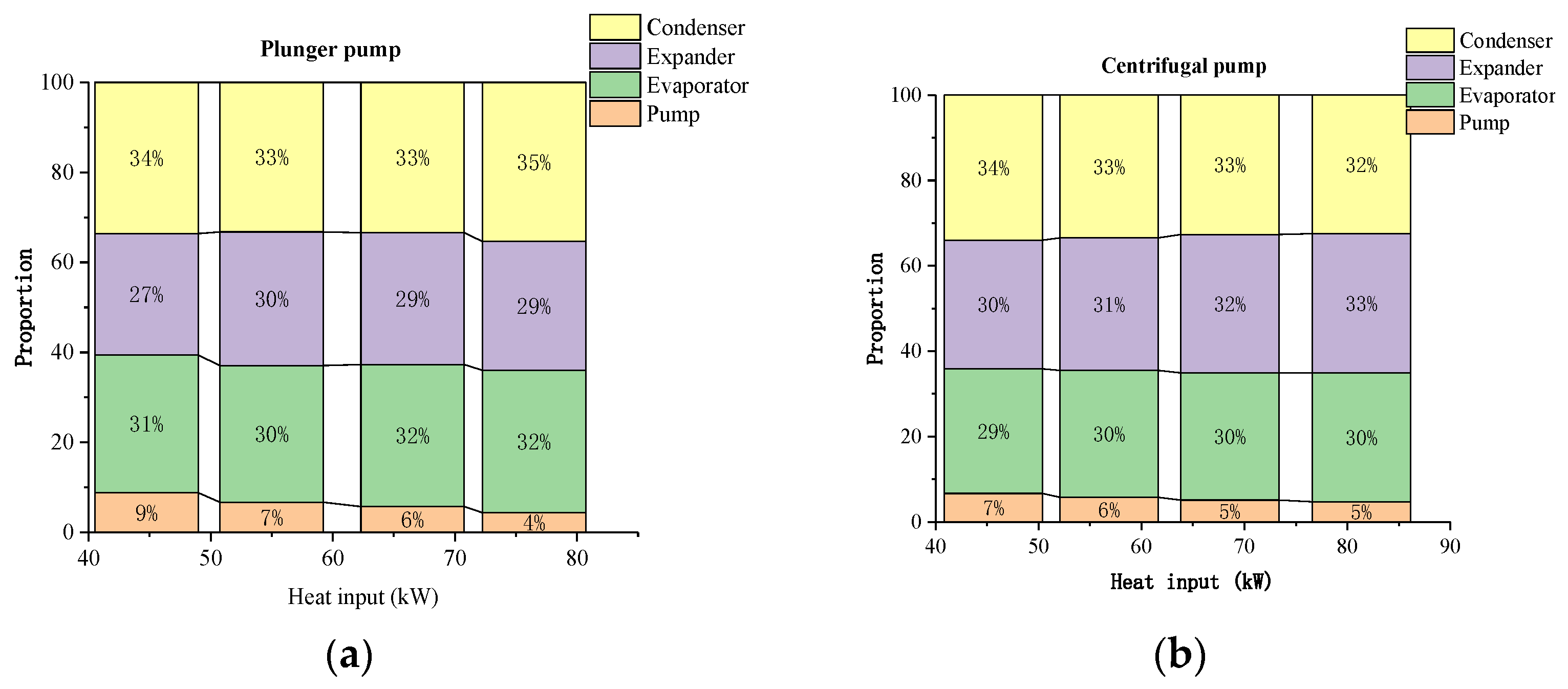
4.2. Detailed Components’ Behavior

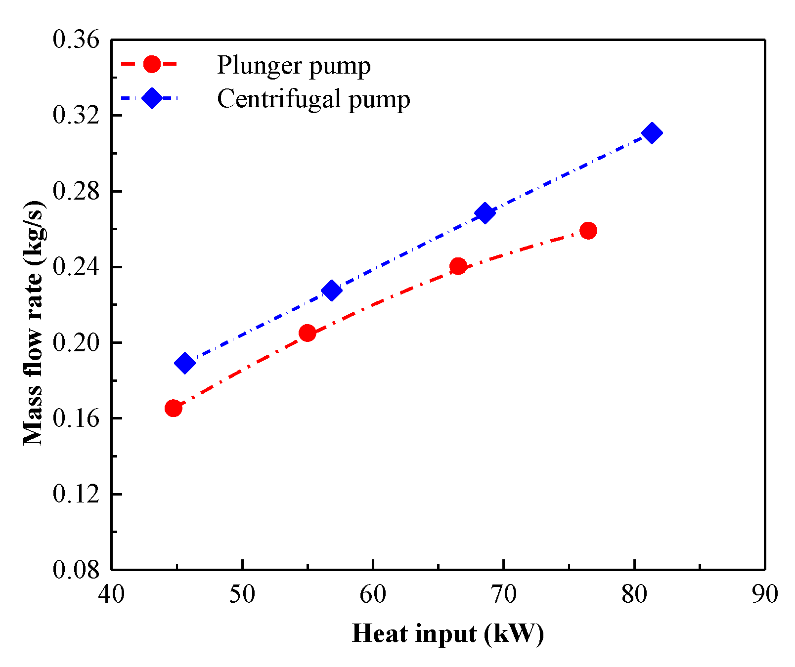
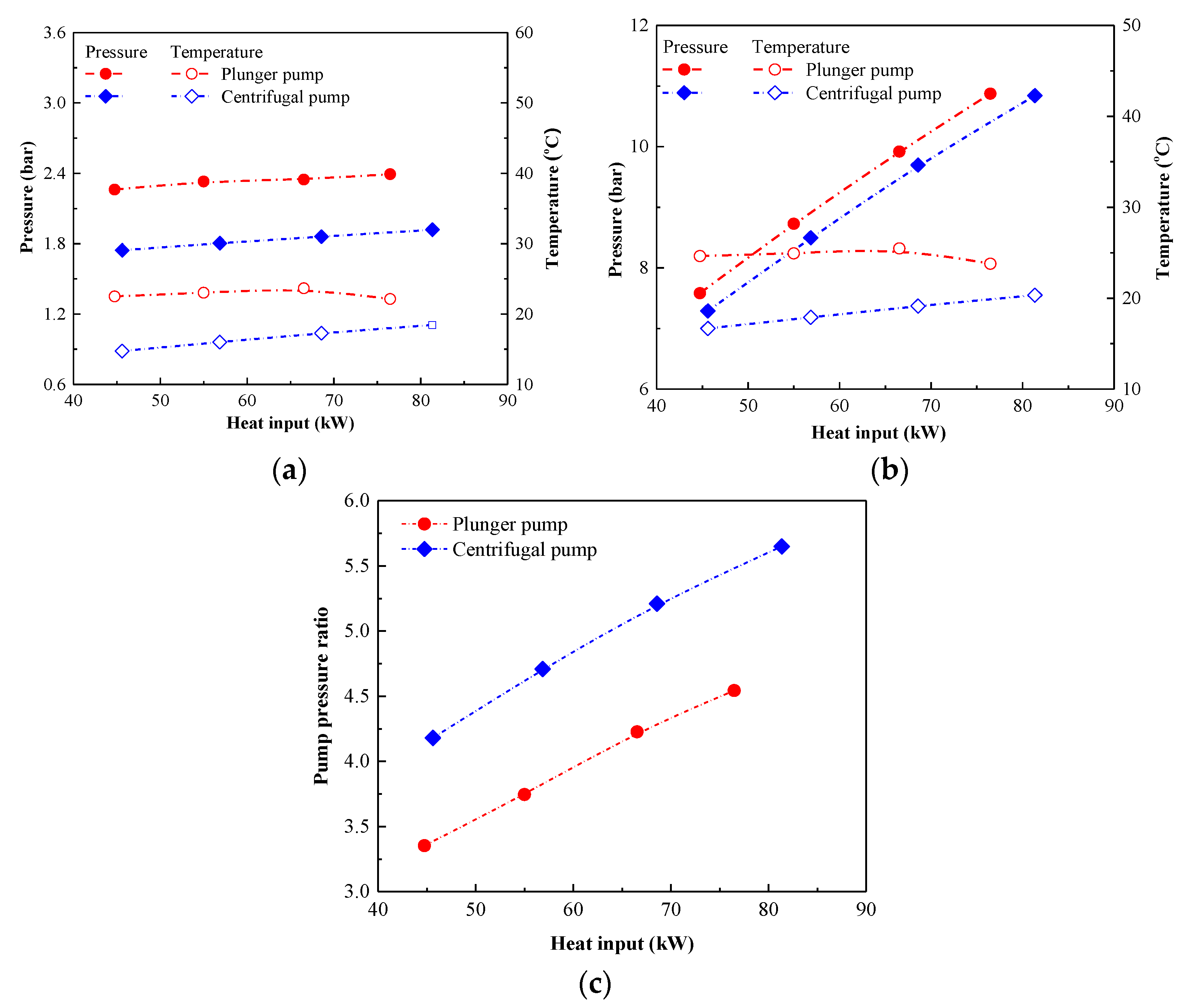
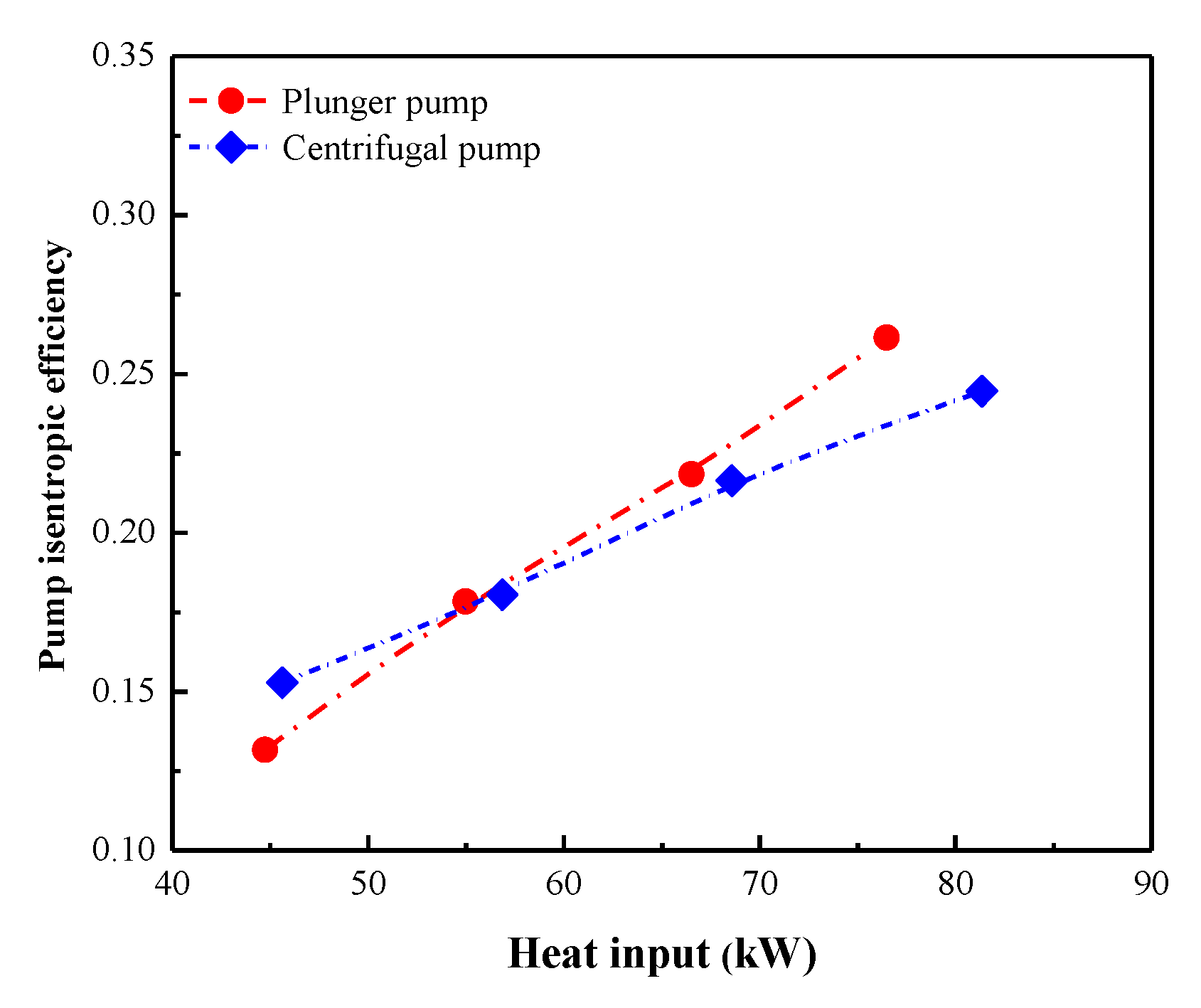
4.2.1. Pump Behavior

The pump shaft power cannot be tested and is expressed by Equation (8). Figure 7 demonstrates the details of shaft power using the plunger pump and centrifugal pump with heat input. Apparently, the pump shaft power of the centrifugal pump keeps increasing with heat input, which may be caused by the increase in mass flow rate and pump enthalpy difference. However, the shaft power of the plunger pump presents a slight decrease when heat inputs exceed 66.53 kW because of the higher sensitivity to the environmental temperature. The pump shaft power using the centrifugal pump increases from 0.51 kW to 0.85 kW, which is 37% higher than that of the plunger pump.
The pump isentropic efficiency can be considered as an important parameter to ascertain pump characteristics. Figure 8 displays the pump isentropic efficiency of the plunger pump and centrifugal pump. The isentropic efficiency keeps increasing with heat input because the pump compression process gets closer to the ideal isentropic process. The isentropic efficiency of the plunger pump and centrifugal pumps is in the range of 13.2–26.1% and 15.3–24.5%, respectively. The pump isentropic efficiency is really low because there is no specialized pump for the ORC system. Moreover, the centrifugal pump isentropic efficiency is higher than the plunger pump for low heat inputs, while a reverse trend for higher input heats. Meanwhile, the low pump isentropic efficiency reminds us that enhancing the pump’s behavior is vital for the improvement in ORC performance.

4.2.2. Heat Exchanger Behavior

The details of evaporator and condenser heat transfer coefficients with heat input using the plunger pump and centrifugal pump are plotted in Figure 9. In Figure 9a, the evaporator heat transfer coefficient of the centrifugal pump keeps increasing, whereas that of the plunger pump displays a parabolic trend with a maximum with heat input, which may be caused by both the evaporator heat transfer rate and LMTD. The condenser heat transfer coefficient keeps rising with heat input in Figure 9, this is because of an increasing expander outlet temperature. The increasing condenser heat transfer rate is greater than that of condenser LMTD, which causes an increasing condenser heat transfer coefficient. Meanwhile, the cycle using the centrifugal pump has a relatively higher heat transfer coefficient than that using the plunger pump (whether evaporator or condenser). The evaporator heat transfer coefficients for the cycle using the plunger pump and centrifugal pump are in the range of 116.45–147.01 W/m2 °C and 126.95–149.58 W/m2 °C, and the corresponding condenser heat transfer coefficients are 1003.18–1371.33 W/m2°C and 1092.74–1608.27 W/m2 °C, respectively.
As for the ORC simulation, the pressure drop in the evaporation and condensation processes are usually ignored. However, for the actual cycle, having pressure drops can decrease the expander inlet pressure, and thus affect the overall system property. Figure 10 demonstrates the variation of condenser and evaporator pressure drop with heat input using the plunger pump and centrifugal pump. Obviously, the pressure drops for evaporator and condenser increase with the heat input, which may be caused by the increasing mass flow rate. A small difference in the evaporator pressure drop appeared between the plunger pump and the centrifugal pump. However, when the heat inputs raise from 40 kW to 82 kW, the condenser pressure drops using the centrifugal pump are 0.13–0.53 bar, which is 0.07 bar higher than that using the plunger pump. The evaporator pressure drops are in the range of 0.45–0.65 bar. It indicates that the pressure drop should be considered for the ORC simulation and decreasing the pressure drop is one way to improve the system performance.
The variation of temperature utilization rate with heat input using the plunger pump and centrifugal pump is plotted in Figure 11. For a specific heat source temperature, a higher thermal efficiency does not represent a higher net power output. Therefore, the temperature utilization rate is used to appraise the heat source utilization. As illustrated in Figure 11, the temperature utilization rate for the centrifugal pump has a slight decrease whereas the plunger pump has almost no change with the heat input. The average heat source temperature utilization rate for the centrifugal pump is about 30%, which is 5% higher than that of the plunger pump, indicating that the centrifugal pump absorbs more heat than the plunger pump at the same heat source condition.

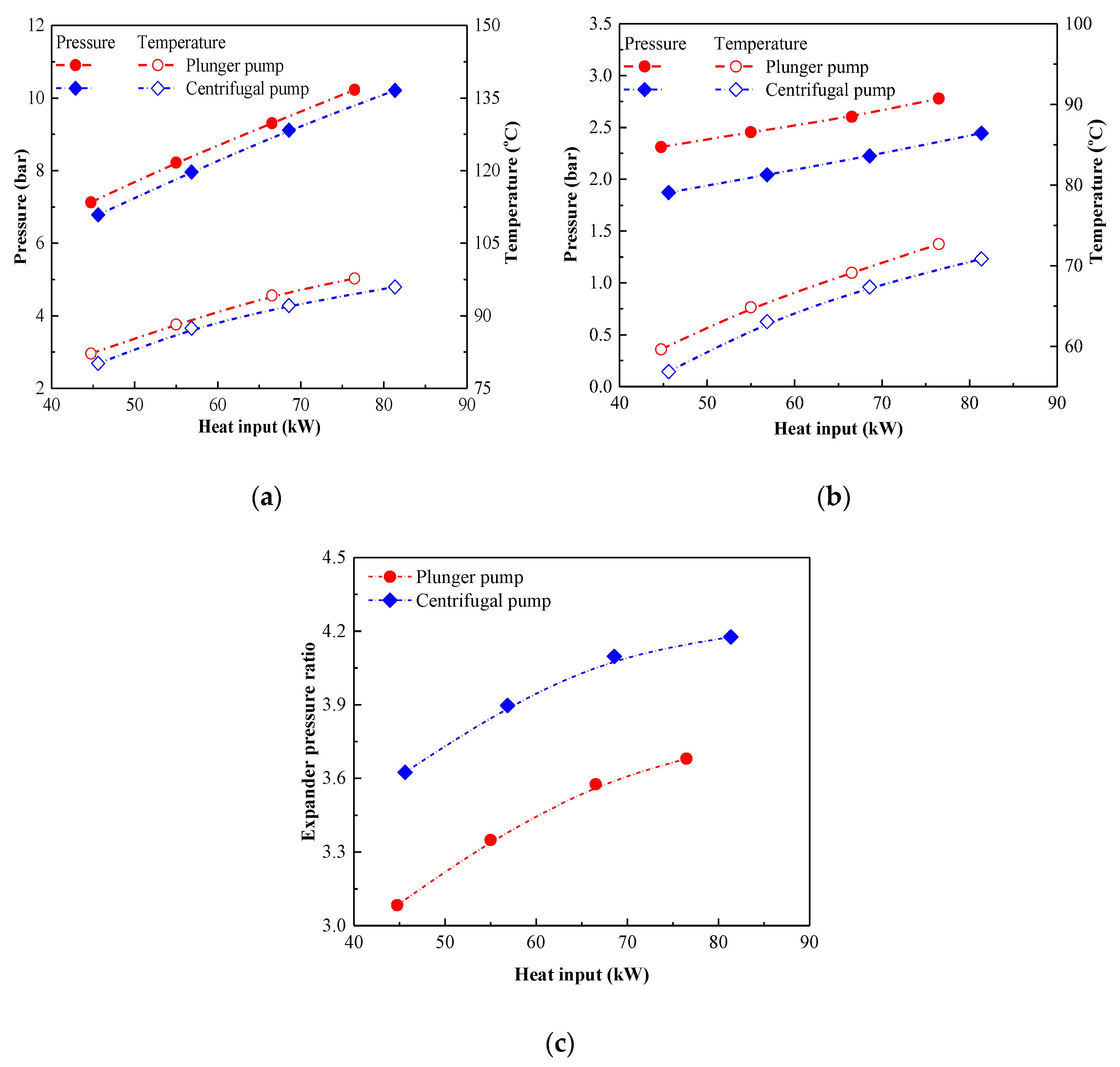
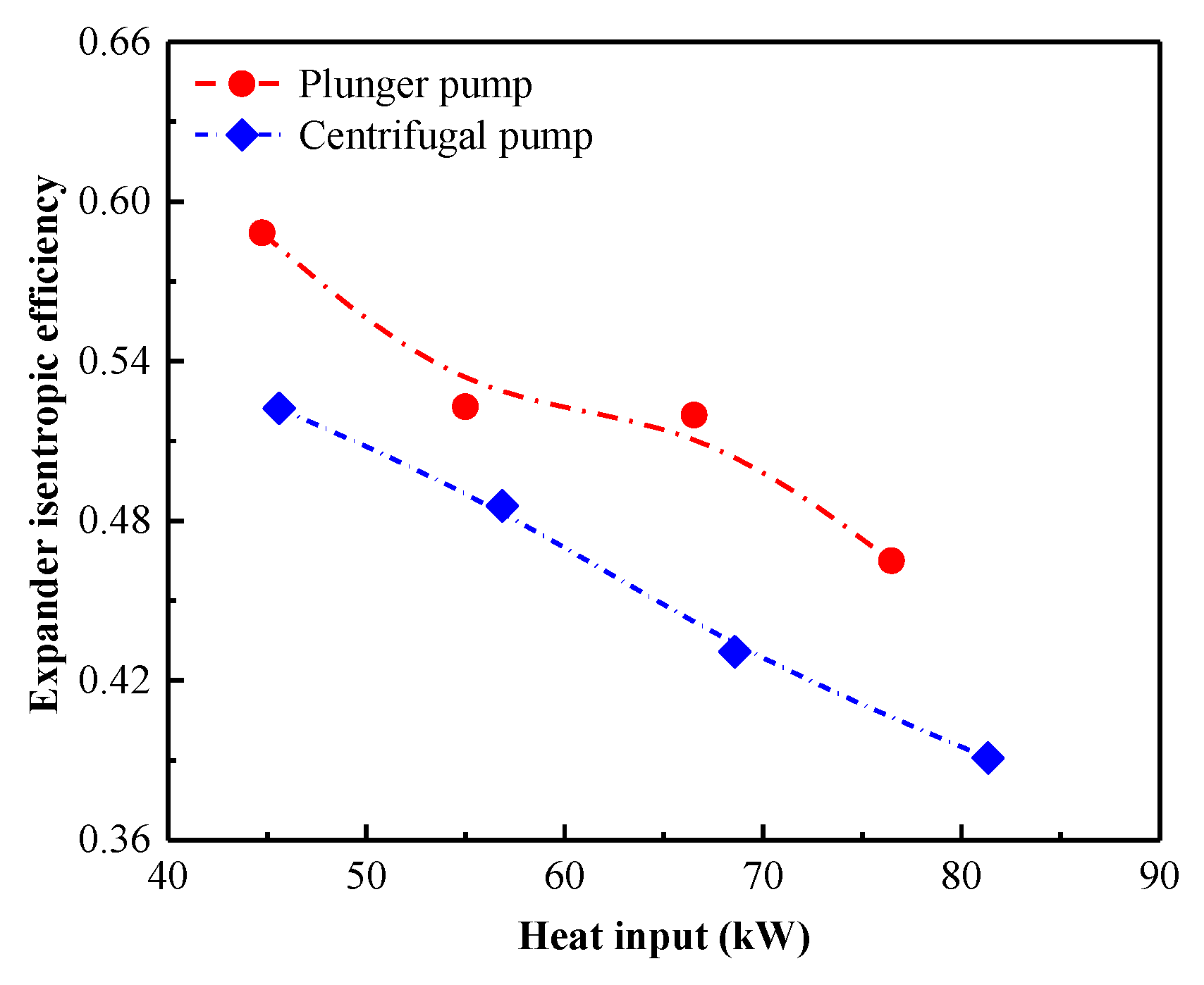
4.2.3. Expander Behavior

Figure 12 shows the expander isentropic efficiency with heat input using the plunger pump and centrifugal pump. It should be reminded that the scroll expander is designed with a nominal expander shaft power of 10 kW, indicating a heat input of 40–200 kW is needed. However, the heat input is set from 45 kW to 85 kW because of the power limitation. Therefore, the expander isentropic efficiency presents an apparent decrease trend from 58.8% to 39.1% with heat input because of the insufficient expansion. The expander isentropic efficiency for the plunger pump is in the range of 46.5–58.8%, which is 12.6% higher than that of the centrifugal pump.
The variation of electrical power with heat input using the plunger pump and centrifugal pump is illustrated in Figure 13. The electrical power for the centrifugal pump rises from 1.83 kW to 3.01 kW, while that of the plunger pump is in the range of 1.76–2.87 kW. The reason is that the increment in pressure difference causes an increase in the expander rotational speed, resulting in an increase in electrical power. The electrical power has a small difference using the plunger pump and centrifugal pump, indicating that the electric power is insensitive on the pump types.

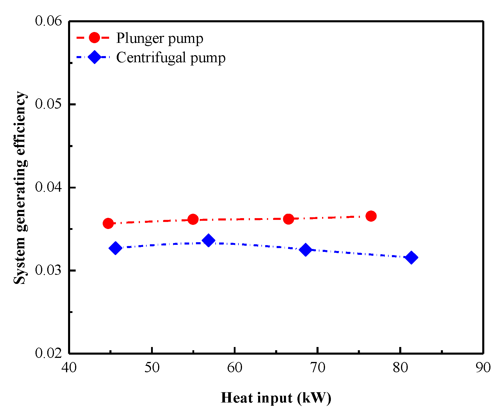
4.3. Overall System Performance

Figure 14 displays the system generating efficiency of the plunger pump and centrifugal pump. In this study, system generating efficiency is utilized as an evaluation criterion for this system, which is obtained based on the net electrical power and heat input. The system generating efficiency has no obvious change with heat input, demonstrating that the system generating efficiency has little effect on the heat input. The increasing net electrical power and the increasing heat input enable the almost unchanged system generating efficiency. The system generating efficiency for the plunger pump is approximately 3.63%, which is 12.51% higher than that of the centrifugal pump. One reason for the low overall system performance is that the pump consumed more power (as shown in Figure 7).
Figure 15 presents the details of the exergy destruction of the four important components with the heat input using the plunger pump and centrifugal pump. It is obvious that the exergy destruction for the evaporator, expander and condenser keep rising, whereas that of the pump almost has no change with the heat input. Besides, the exergy destruction of the piston pump is almost the same as that of the centrifugal pump. However, for the other three components, the exergy destruction using the centrifugal pump is higher than that using the plunger pump, because of the relatively higher mass flow rate for the centrifugal pump. For a specific heat input of 68.6 kW using the plunger pump, the exergy destruction for the pump, evaporator, expander, and condenser is 0.5 kW, 3 kW, 2.5 kW, and 3.2 kW, respectively.
To ascertain which component contributes the maximum exergy destruction, the proportion of exergy destruction for each component using the plunger pump and centrifugal pump is shown in Figure 16. For the plunger pump and centrifugal pump, the exergy destruction for the evaporator, expander and condenser is almost 30%, indicating that improving the temperature matching between the cycle and the heat (cold) source is a way to improve the system property.

5. Conclusions

The system behaviors using the plunger pump and centrifugal pump have been investigated experimentally. A 10 kW R245fa-based experimental prototype is adopted. The heat source temperature for both pump experiments was 85–106 °C. The heat inputs for the plunger pump and centrifugal pump are in the range of 44.74–76.48 kW and 45.61–81.35 kW, respectively. Simultaneously, the mass flow rates of the plunger pump are from 0.16–0.26kg/s and those of the centrifugal pump are in the range of 0.19–0.31 kg/s. The temperature utilization rate is used to appraise the heat source utilization. The detailed components’ behaviors with the varying heat input are discussed, while the system generating efficiency is examined. The exergy destruction of the four main components is addressed. The conclusions are summarized below:
(1) The mass flow rates of the centrifugal pump are from 0.19–0.31 kg/s, which is 19% higher than that of the plunger pump. Compared with the plunger pump, the centrifugal pump owns a relatively higher mass flow rate and more pump shaft power.
(2) A small difference of evaporator pressure drop appeared between the plunger pump and the centrifugal pump. The condenser pressure drops using the centrifugal pump are 0.13–0.53 bar, while the evaporator pressure drops are in the range of 0.45–0.65 bar, demonstrating that the pressure drop should be considered for the ORC simulation.
(3) The average heat source temperature utilization rate for the centrifugal pump is about 30%, which is 5% higher than that of the plunger pump, indicating that the centrifugal pump absorbs more heat than the plunger pump at a same heat source condition.
(4) The electrical power for the centrifugal pump rises from 1.83 kW to 3.01 kW, while that of the plunger pump is in the range of 1.76–2.87 kW. The electrical power has a small difference using the plunger pump and centrifugal pump, indicating that the electrical power is insensitive of the pump types. The system generating efficiency for the plunger pump is approximately 3.63%, which is 12.51% higher than that of the centrifugal pump. It indicates that the plunger pump is more suitable for the ORC system in this study. The system generating efficiency is insensitive of the heat input.
(5) No matter which pump is used in the ORC, evaporator, expander, and condenser exergy destruction accounts for almost 30%.
(6) The exergy destruction for evaporators, expanders, and condensers is almost 30%, indicating that improving temperature matching between the system and the heat (cold) source is a way to improve the system property

Author Contributions

Y.-q.F., Q.W. and T.-C.H. conceived of the presented idea. X.W. and C.-H.L. developed the theory and performed the computations. Z.-x.H. and M.S. verified the analytical methods. All authors discussed the results and contributed to the final manuscript. All authors have read and agreed to the published version of the manuscript.

Funding

This research work has been supported by the National Natural Science Foundation of China (51806081), the Key Research and Development Program of Jiangsu Province, China (BE2019009-4), the Natural Science Foundation of Jiangsu Province (BK20180882), the China Postdoctoral Science Foundation (2018M632241), the 2019 Scholarship of the Knowledge Center on Organic Rankne Cycle (KCORC, www.kcorc.org), the Key Research and Development Program of Zhenjiang City, China (SH2019008), and the Key Project of Taizhou New Energy Research Institute, Jiangsu University, China (2018-20). The authors are grateful for the Ministry of Science and Technology, Taiwan under the grants of Contract No. MOST 107-2221-E-027-091, and by “Research Center of Energy Conservation for New Generation of Residential, Commercial, and Industrial Sector” from The Featured Areas Research Center Program within the framework of the Higher Education Sprout Project by the Ministry of Education (MOE) in Taiwan.

Conflicts of Interest

The authors declare no conflict of interest.

References

  1. Johnson, I.; Choate, W.T.; Davidson, A. Waste Heat Recovery: Technology and Opportunities in U.S. Industry; BCS, lnc.: Laurel, MD, USA, 2008. [Google Scholar]
  2. Feng, Y.Y.; Zhang, Y.Y.; Li, B.B.; Yang, J.J.; Shi, Y. Comparison between regenerative organic Rankine cycle (RORC) and basic organic Rankine cycle (BORC) based on thermoeconomic multi-objective optimization considering exergy efficiency and levelized energy cost (LEC). Energy Convers. Manag. 2015, 96, 58–71. [Google Scholar] [CrossRef]
  3. Feng, Y.Y.; Hung, T.C.; Greg, K.; Zhang, Y.Y.; Li, B.B.; Yang, J.F. Thermoeconomic comparison between pure and mixture working fluids for low-grade organic Rankine cycles (ORCs). Energy Convers. Manag. 2015, 106, 859–872. [Google Scholar] [CrossRef]
  4. Peris, B.; Navarro-Esbr, J.; Moles, F.; Martí, J.J.; Mota-Babiloni, A. Experimental characterization of an Organic Rankine Cycle (ORC) for micro-scale CHP applications. Appl. Ther. Eng. 2015, 79, 1–8. [Google Scholar] [CrossRef]
  5. Capata, R.; Toro, C. Feasibility analysis of a small-scale ORC energy recovery system for vehicular application. Energy Convers. Manag. 2014, 86, 1078–1090. [Google Scholar] [CrossRef]
  6. Freeman, J.; Hellgardt, K.; Markides, C.N. An assessment of solar-powered organic Rankine cycle systems for combined heating and power in UK domestic applications. Appl. Energy 2015, 138, 605–620. [Google Scholar] [CrossRef] [Green Version]
  7. Pantano, F.; Capata, R. Expander selection for an on board ORC energy recovery system. Energy 2017, 141, 1084–1096. [Google Scholar] [CrossRef] [Green Version]
  8. Atiz, A.; Karakilcik, H.; Erden, M.; Karakilcik, M. Investigation energy, exergy and electricity production performance of an integrated system based on a low-temperature geothermal resource and solar energy. Energy Convers. Manag. 2019, 195, 798–809. [Google Scholar] [CrossRef]
  9. Mathias, J.J.; Johnston, J.J.; Cao, J.J.; Priedeman, D.D.; Christensen, R.N. Experimental testing of gerotor and scroll expanders used in, and energetic and exergetic modeling of, an organic Rankine cycle. J. Energy Res. Technol. Trans. ASME 2009, 131, 21–24. [Google Scholar] [CrossRef]
  10. Lei, B.; Wang, J.-F.; Wu, Y.-T.; Ma, C.-F.; Wang, W.; Zhang, L.; Li, J.-Y. Experimental study and theoretical analysis of a Roto-Jet pump in small scale organic Rankine cycles. Energy Convers. Manag. 2016, 111, 198–204. [Google Scholar] [CrossRef]
  11. Bianchi, G.; Fatigati, F.; Murgia, S.; Cipollone, R.; Contaldi, G. Modeling and experimental activities on a small-scale sliding vane pump for ORC-based waste heat recovery applications. Energy Procedia 2016, 101, 1240–1247. [Google Scholar] [CrossRef]
  12. Villani, M.; Tribioli, L. Comparison of different layouts for the integration of an organic Rankine cycle unit in electrified powertrains of heavy duty Diesel trucks. Energy Convers. Manag. 2019, 187, 248–261. [Google Scholar] [CrossRef]
  13. Zeleny, Z.; Vodicka, V.; Novotny, V.; Mascuch, J. Gear pump for low power output ORC—An efficiency analysis. Energy Procedia 2017, 129, 1002–1009. [Google Scholar] [CrossRef]
  14. Xu, W.; Zhang, J.J.; Zhao, L.; Deng, S.; Zhang, Y. Novel experimental research on the compression process in organic Rankine cycle (ORC). Energy Convers. Manag. 2017, 137, 1–11. [Google Scholar] [CrossRef]
  15. Carraro, G.; Pallis, P.; Leontaritis, A.D.; Karellas, S.; Vourliotis, P.; Rech, S.; Lazzaretto, A. Experimental performance evaluation of a multi-diaphragm pump of a micro-ORC system. Energy Procedia 2017, 129, 1018–1025. [Google Scholar] [CrossRef]
  16. Bianchi, M.; Branchini, L.; Casari, N.; Pascale, D.; Melino, F.; Ottaviano, S.; Pinelli, M.; Spina, P.; Suman, A. Experimental analysis of a micro-ORC driven by piston expander for low-grade heat recovery. Appl. Ther. Eng. 2019, 148, 1278–1291. [Google Scholar] [CrossRef]
  17. Zhang, H.H.; Xi, H.; He, Y.Y.; Zhang, Y.Y.; Ning, B. Experimental study of the organic rankine cycle under different heat and cooling conditions. Energy 2019, 180, 678–688. [Google Scholar] [CrossRef]
  18. Xi, H.; He, Y.Y.; Wang, J.J.; Huang, Z.H. Transient response of waste heat recovery system for hydrogen production and other renewable energy utilization. Int. J. Hydrogen Energy 2019, 44, 15985–15996. [Google Scholar] [CrossRef]
  19. Abam, F.F.; Ekwe, E.E.; Effiom, S.S.; Ndukwu, M.M.; Briggs, T.T.; Kadurumba, C.H. Optimum exergetic performance parameters and thermo-sustainability indicators of low-temperature modified organic Rankine cycles (ORCs). Sustain. Energy Technol. Assess. 2018, 30, 91–104. [Google Scholar] [CrossRef]
  20. Aleksandra, B.-G. Pumping work in the organic Rankine cycle. Appl. Ther. Eng. 2013, 51, 781–786. [Google Scholar]
  21. Wu, T.T.; Liu, J.J.; Zhang, L.; Xu, X.J. Experimental study on multi-stage gas-liquid booster pump for working fluid pressurization. Appl. Ther. Eng. 2017, 126, 9–16. [Google Scholar] [CrossRef]
  22. Meng, F.F.; Zhang, H.H.; Yang, F.F.; Hou, X.X.; Lei, B.; Zhang, L. Study of efficiency of a multistage centrifugal pump used in engine waste heat recovery application. Appl. Ther. Eng. 2017, 110, 779–786. [Google Scholar] [CrossRef]
  23. Yang, Y.Y.; Zhang, H.H.; Xu, Y.Y.; Yang, F.B.; Wu, Y.Y.; Lei, B. Matching and operating characteristics of working fluid pumps with organic Rankine cycle system. Appl. Ther. Eng. 2018, 142, 622–631. [Google Scholar] [CrossRef]
  24. Sun, H.H.; Qin, J.; Hung, T.C.; Hua, H.H.; Ya, P.P.; Lin, C.H. Effect of flow losses in heat exchangers on the performance of organic Rankine cycle. Energy 2019, 172, 391–400. [Google Scholar] [CrossRef]
  25. Feng, Y.Y.; Hung, T.C.; He, Y.Y.; Wang, Q.; Wang, S.; Li, B.B.; Lin, J.J.; Zhang, W.P. Operation characteristic and performance comparison of organic Rankine cycle (ORC) for low-grade waste heat using R245fa, R123 and their mixtures. Energy Convers. Manag. 2017, 144, 153–163. [Google Scholar] [CrossRef]
  26. Feng, Y.Q.; Hung, T.C.; Wu, S.S.; Lin, C.C.; Li, B.B.; Huang, K.K.; Qin, J. Operation characteristic of a R123-based organic Rankine cycle depending on working fluid mass flow rates and heat source temperature. Energy Convers. Manag. 2017, 131, 55–68. [Google Scholar] [CrossRef]
  27. Yang, S.S.; Hung, T.C.; Feng, Y.Y.; Wu, C.C.; Wong, K.K.; Huang, K.C. Experimental investigation on a 3 kW organic Rankine cycle for low grade waste heat under different operation parameters. Appl. Ther. Eng. 2017, 113, 756–764. [Google Scholar] [CrossRef]
  28. D’Amico, F.; Pallis, P.; Leontaritis, A.D.; Karellas, S.; Kakalis, N.M.; Rech, S.; Lazzaretto, A. Semi-empirical model of a multi-diaphragm pump in an Organic Rankine Cycle (ORC) experimental unit. Energy 2018, 143, 1056–1071. [Google Scholar] [CrossRef]
  29. Liu, L.L.; Zhu, T.; Wang, T.T.; Gao, N.P. Experimental investigation on the effect of working fluid charge in a small-scale Organic Rankine Cycle under off-design conditions. Energy 2019, 174, 664–677. [Google Scholar] [CrossRef]
  30. Yang, X.X.; Xu, J.J.; Miao, Z.; Zou, J.J.; Yu, C. Operation of an organic Rankine cycle dependent on pumping flow rates and expander torques. Energy 2015, 90, 864–878. [Google Scholar] [CrossRef]
  31. Pei, G.; Li, J.; Li, Y.Y.; Wang, D.D.; Ji, J. Construction and dynamic test of a small-scale organic rankine cycle. Energy 2011, 36, 3215–3223. [Google Scholar] [CrossRef]
  32. Galindo, J.; Ruiz, S.; Dolz, V.; Royo-Pascual, L.; Haller, R.; Nicolas, B.; Glavatskaya, Y. Experimental and thermodynamic analysis of a bottoming Organic Rankine Cycle (ORC) of gasoline engine using swash-plate expander. Energy Convers. Manag. 2015, 103, 519–532. [Google Scholar] [CrossRef]
  33. Dumont, O.; Quoilin, S.; Lemort, V. Experimental investigation of a reversible heat pump/organic Rankine cycle unit designed to be coupled with a passive house to get a Net Zero Energy Building. Int. J. Refrig. 2015, 54, 190–203. [Google Scholar] [CrossRef]
  34. Gao, P.; Wang, Z.Z.; Wang, L.L.; Lu, H.T. Technical feasibility of a gravity-type pumpless ORC system with one evaporator and two condensers. Appl. Ther. Eng. 2018, 145, 569–575. [Google Scholar] [CrossRef]
  35. Bao, H.H.; Ma, Z.Z.; Roskilly, A.P. Chemisorption power generation driven by low grade heat – Theoretical analysis and comparison with pumpless ORC. Appl. Energy 2017, 186, 282–290. [Google Scholar] [CrossRef]
  36. Jiang, L.; Lu, H.H.; Wang, R.R.; Wang, L.L.; Gong, L.L.; Lu, Y.Y.; Roskilly, A.P. Investigation on an innovative cascading cycle for power and refrigeration cogeneration. Energy Convers. Manag. 2017, 145, 20–29. [Google Scholar] [CrossRef] [Green Version]
  37. Feng, Y.Y.; Hung, T.C.; Su, T.T.; Wang, S.; Wang, Q.; Yang, S.S.; Lin, J.J.; Lin, C.H. Experimental investigation of a R245fa-based organic Rankine cycle adapting two operation strategies: Stand alone and grid connect. Energy 2017, 141, 1239–1253. [Google Scholar] [CrossRef]
  38. Sun, H.H.; Qin, J.; Hung, T.C.; Lin, C.C.; Lin, Y.F. Performance comparison of organic Rankine cycle with expansion from superheated zone or two-phase zone based on temperature utilization rate of heat source. Energy 2018, 149, 566–576. [Google Scholar] [CrossRef]
Figure 1. Schematic diagram of the experimental bench.
Energies 13 01141 g001
Figure 2. The pictures of (a) experimental setup; (b) the electrical load; (c) the circuit and (d) centrifugal pump.
Energies 13 01141 g002aEnergies 13 01141 g002b
Figure 3. T-s plot of the organic Rankine cycle system.
Energies 13 01141 g003
Figure 4. Mass flow rates with heat input using the plunger pump and centrifugal pump.
Energies 13 01141 g004
Figure 5. Pressure and temperature at the pump inlet and outlet with heat input using the plunger pump and centrifugal pump: (a) pressure and temperature at the pump inlet; (b) pressure and temperature at the pump outlet and (c) pump pressure ratios.
Energies 13 01141 g005
Figure 6. Temperature and pressure at the expander inlet and outlet with heat input using the plunger pump and centrifugal pump: (a) pressure and temperature at the expander inlet; (b) pressure and temperature at the expander outlet; (c) expander pressure ratios.
Energies 13 01141 g006
Figure 7. Pump shaft power with heat input using the plunger pump and centrifugal pump.
Energies 13 01141 g007
Figure 8. Pump isentropic efficiency with heat input using the plunger pump and centrifugal pump.
Energies 13 01141 g008
Figure 9. Evaporator and condenser heat transfer coefficients with heat input using the plunger pump and centrifugal pump: (a) evaporator heat transfer coefficients; (b) condenser heat transfer coefficients.
Energies 13 01141 g009
Figure 10. Condenser and evaporator pressure drop with heat input using the plunger pump and centrifugal pump.
Energies 13 01141 g010
Figure 11. Temperature utilization rate with heat input using the plunger pump and centrifugal pump.
Energies 13 01141 g011
Figure 12. Expander isentropic efficiency with heat input using the plunger pump and centrifugal pump.
Energies 13 01141 g012
Figure 13. Electrical power with heat input using the plunger pump and centrifugal pump.
Energies 13 01141 g013
Figure 14. System generating efficiency with heat input using the plunger pump and centrifugal pump.
Energies 13 01141 g014
Figure 15. Exergy destruction of the four important components using the plunger pump and centrifugal pump: (a) pump exergy destruction; (b) evaporator exergy destruction; (c) expander exergy destruction; (d) condenser exergy destruction.
Energies 13 01141 g015
Figure 16. The proportion of exergy destruction for each component with heat input using the plunger pump and centrifugal pump: (a) the proportion of exergy destruction using the plunger pump; (b) the proportion of exergy destruction using the centrifugal pump.
Energies 13 01141 g016
Table 1. Parameters of plate heat exchangers.
ComponentMaximum TemperatureTotal VolumeTotal Heat Transfer AreaMaximum Pressure
Heat exchanger200 °C8.848 L4.175 m230 bar
Table 2. Parameters of the scroll expander.
ComponentVolume RatioInspiratory VolumeGear HeightBasic Circle Radius
Scroll expander2.9523.56 m3/hr48.2 mm4.456 mm
Table 3. Parameters of the plunger pump and centrifugal pump.
ComponentsMaximum Pressure(bar)Maximum Flow(L/min)Temperature Resistance (°C)Nominal Speed (RPM)
Plunger pump2015.540850
Centrifugal pump2536.71203500
Table 4. The measuring devices and the uncertainties for system parameters.
ItemTypeMeasurement RangeDevice Uncertainty
TemperatureT-type0–623.15 K±0.3 K
PressureJPT-131S0–30 bar±0.5% F.S
Flow rateGPI S0501.9–37.9 L/min±3% L/min
Rotation speedUT-37210–99,999 rpm±3% rpm
Electrical powerPA310 0.5%
Pump shaft power 3.9%
Pump isentropic efficiency 4.5%
Evaporator heat transfer coefficient 1.9%
Condenser heat transfer coefficient 2.2%
Expander isentropic efficiency 4.7%
System generating efficiency 1.2%
Table 5. The environment temperature for using the plunger pump.
Heat input (kW)38.748.858.263.8
Environment temperature (°C)23.523.524.021.5
Table 6. The environment temperature for using the centrifugal pump.
Heat input (kW)46.056.266.677.3
Environment temperature (°C)17.517.318.918.5

