Article

Solar Radiation Allocation and Spatial Distribution in Chinese Solar Greenhouses: Model Development and Application

College of Horticulture, Gansu Agricultural University, Lanzhou 730070, China
*
Author to whom correspondence should be addressed.
Energies 2020, 13(5), 1108; https://doi.org/10.3390/en13051108
Submission received: 3 January 2020 / Revised: 16 February 2020 / Accepted: 27 February 2020 / Published: 2 March 2020
(This article belongs to the Special Issue Low and Zero Energy Highly Performing Buildings)

Abstract

:
Solar radiation is the sole energy source for Chinese solar greenhouse agriculture. A favorable light environment is the foundation of a desirable crop growth environment, and it is key in solar greenhouse design. In this study, a mathematical model is established to quantitatively evaluate the solar greenhouse light environment. The model was developed considering the greenhouse shape parameters, materials’ optical properties, and interior solar radiation evolution, including the beam radiation, diffuse radiation, and multi-reflection. The model was validated under different weather conditions, and the results reveal a mean percentage error of 1.67 and 10.30% for clear sunny weather and cloudy weather, respectively, and a determination coefficient of 0.9756. By using this model, the solar radiation allocation in a solar greenhouse was calculated to determine the solar radiation availability for the heat-storage north wall and the entire greenhouse, and the dynamical spatial distribution of the solar radiation was obtained to describe the light environment quality. These allow the optimization of the greenhouse lighting regulation and planting pattern. Moreover, several optimizing measures are derived according to the model for improving the low-light environment near the north wall and maximizing the north wall’s heat storage/release capacity in a solar greenhouse.

1. Introduction

The emergence and development of greenhouses have overturned the cultivation patterns of traditional agriculture, allowing plant growth to occur beyond the limitations of the natural environment by creating a growing microclimate isolated from the external conditions [1]. This all-season production with high efficiency makes it possible to secure the food supply for the ever-increasing population and ensure the sustainable development of human society [2]. However, the high cultivation output of greenhouse agriculture requires significant energy consumption and high capital [3]. For heating purpose, large amounts of fossil fuel, natural gas, liquefied petroleum gas, and various expensive heating devices are required in greenhouses, especially during cold seasons; fossil fuel accounts for more than 50% of the total energy consumption, which, in principle, is disadvantageous for sustainable development [4,5]. Thus, greenhouse agriculture requires a choice between efficient and costly production. In recent years, the worldwide application of Chinese solar greenhouses has offered an unprecedented opportunity to break the impasse [6,7]. Unlike conventional greenhouses, Chinese solar greenhouses provide a suitable environment for various crops throughout the year without the requirement of auxiliary lighting and heating, even in areas at latitudes near 40° and when the outside air temperature falls below −10 °C [8].
The smooth operation of a Chinese solar greenhouse under such a harsh environment is achieved owing to its unique building envelope, which is designed to make full use of solar energy [9]. The building envelope of a solar greenhouse is mainly composed of the south roof, north roof, and north wall. The ground under a solar greenhouse also plays an important role in the greenhouse operating system. Generally, the south roof is made of plastic light-passing materials characterized by selective transmittance, and, during nighttime, it is covered with a thermal blanket for insulation. The selective transmittance of the roof materials results in the greenhouse effect. In other words, during the daytime, the south roof is transparent to short-wave solar radiation, performing the lighting function, and opaque to long-wave radiation, performing the heat preservation function [10,11]. Further, during the daytime, the external solar radiation enters the solar greenhouse through the south lighting roof, and a part of it provides energy for the photosynthesis process in crops with dynamic growth indexes (plant height, stem diameter, and leaf area), and the rest falls on the various internal surfaces [12]. The falling solar radiation rises the internal surface temperature, and then warms the inside air via convection; meanwhile, the north wall and the ground, two large building components with high thermal capacity, continuously transfer the solar energy to their interiors from the warming surfaces, and then store it as heat [13,14]. During the nighttime, there is no longer solar energy supply, and the temperature difference between the inside and outside drives the dissipation of the heat energy in the solar greenhouse to the outside environment, which will result in a decrease in the inside air temperature. Meanwhile, the north wall and the ground release the solar energy stored during the daytime to the greenhouse space to compensate for the greenhouse’s heat loss caused by the temperature difference with the outside environment, effectively stabilizing the nocturnal air temperature fluctuation. These processes occurring within the solar greenhouse induce a comfortable temperature environment for off-season crops planting. Therefore, in solar greenhouse cultivation, the spatial distribution of solar radiation directly influences the crop photosynthesis, and the solar radiation allocation in each component affects the construction of the greenhouse’s thermal environment; these two parts constitute the solar greenhouse light environment. It was determined that a favorable light environment is the foundation of a desirable growth environment for crops and is key in the solar greenhouse design.
Although the nocturnal operation of a conventional greenhouse is driven by heating systems, the light environment in the daytime not only functions in crop photosynthesis but also regulates the inside air temperature by the greenhouse effect. The diurnal light environment is very important for the conventional greenhouse energy balance and determines the nocturnal heating demand [15]. Considerable studies have been carried out on the light environment of conventional greenhouses and attempted to reduce the greenhouse running cost by combining the diurnal natural lighting and the nocturnal auxiliary heating. Sethi [11] analyzed the lighting performance of the five most commonly used greenhouse types and tried to select the optimum orientation for lowering the heating load by maximizing the received solar radiation. The investigation was done by developing a mathematical model for computing the hourly transmitted total solar radiation, and the monthly total solar radiation incident on the greenhouse cover was used to estimate the greenhouse’s solar radiation availability. Their results suggested that a greenhouse with an east-west orientation should be used in the northern hemisphere. Similarly, Çakır and Şahin [16] calculated the amount of external solar beam radiation reaching greenhouse covers with different shapes. A comparison among seasonal total solar energy gaining rates was made to assess whether the greenhouses were usable in the cold season in Turkey. However, the solar radiation captured by a greenhouse is more important than the solar radiation falling on the greenhouse cover for evaluating the greenhouse’s lighting performance. Because the solar beam radiation evolution follows the law of the solar trajectory, Gupta et al. [17] investigated the ratio of the transmitted beam radiation falling on each component inside the greenhouse to the total beam radiation entering the greenhouse under clear sunny conditions through a three-dimensional shadow analysis in Auto-CAD. A total solar fraction has been defined to determine the amount of solar energy loss from the transparent sections of the greenhouses. El-Maghlany et al. [18] studied the abilities to capture solar radiation of greenhouses having elliptic curved surface with different aspect ratios. The entering solar radiation was calculated from an integral considering the nonuniform transmittance along the curved surface, and the captured solar radiation was derived from the ratio of the greenhouse’s cover surface to its cultivated land area. Furthermore, to decrease the solar energy loss through the transparent components in a conventional greenhouse, the installation of an opaque wall was suggested, which made the design of the conventional greenhouse similar to that of a solar greenhouse. It was found that the north wall’s insulation can significantly reduce the heating demand of a single span greenhouse in Iran [5,19].
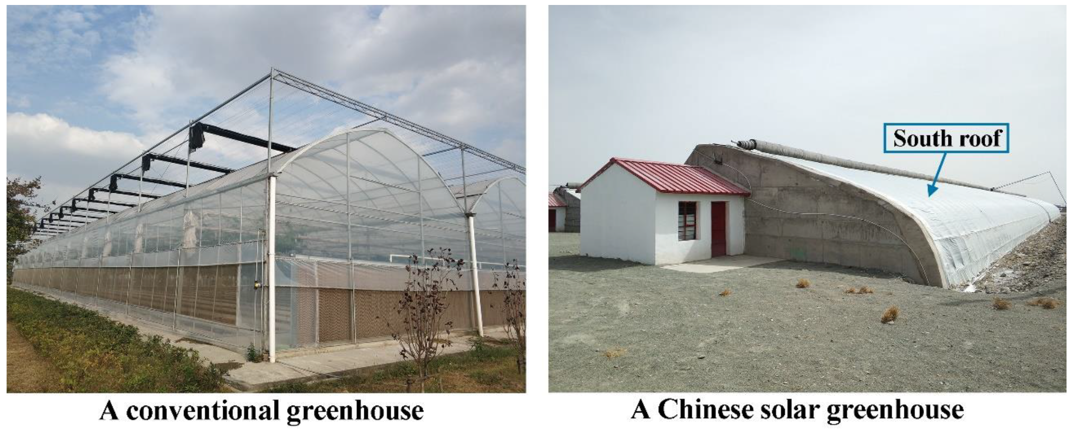
Compared with conventional greenhouses, which have an entirely transparent envelope, the Chinese solar greenhouse is opaque, except for the south roof (for lighting) (Figure 1). The interior solar radiation consists of beam, diffuse, and reflective radiations [20]. With the shadow generated by the opaque components, the solar greenhouse acquires a more complex light distribution, and the solar radiation reflection between various surfaces changes the allocation of the entering solar radiation, which ultimately affects the energy balance of the solar greenhouse system. Therefore, studying the light environment inside solar greenhouses to attain a precise view of the solar radiation allocation and spatial distribution is essential. In past decades, both onsite measurements and model simulations were conducted to evaluate the light environment in solar greenhouses. In Xingyang (34°36′ N and 113°21′ E), China, Wang et al. [
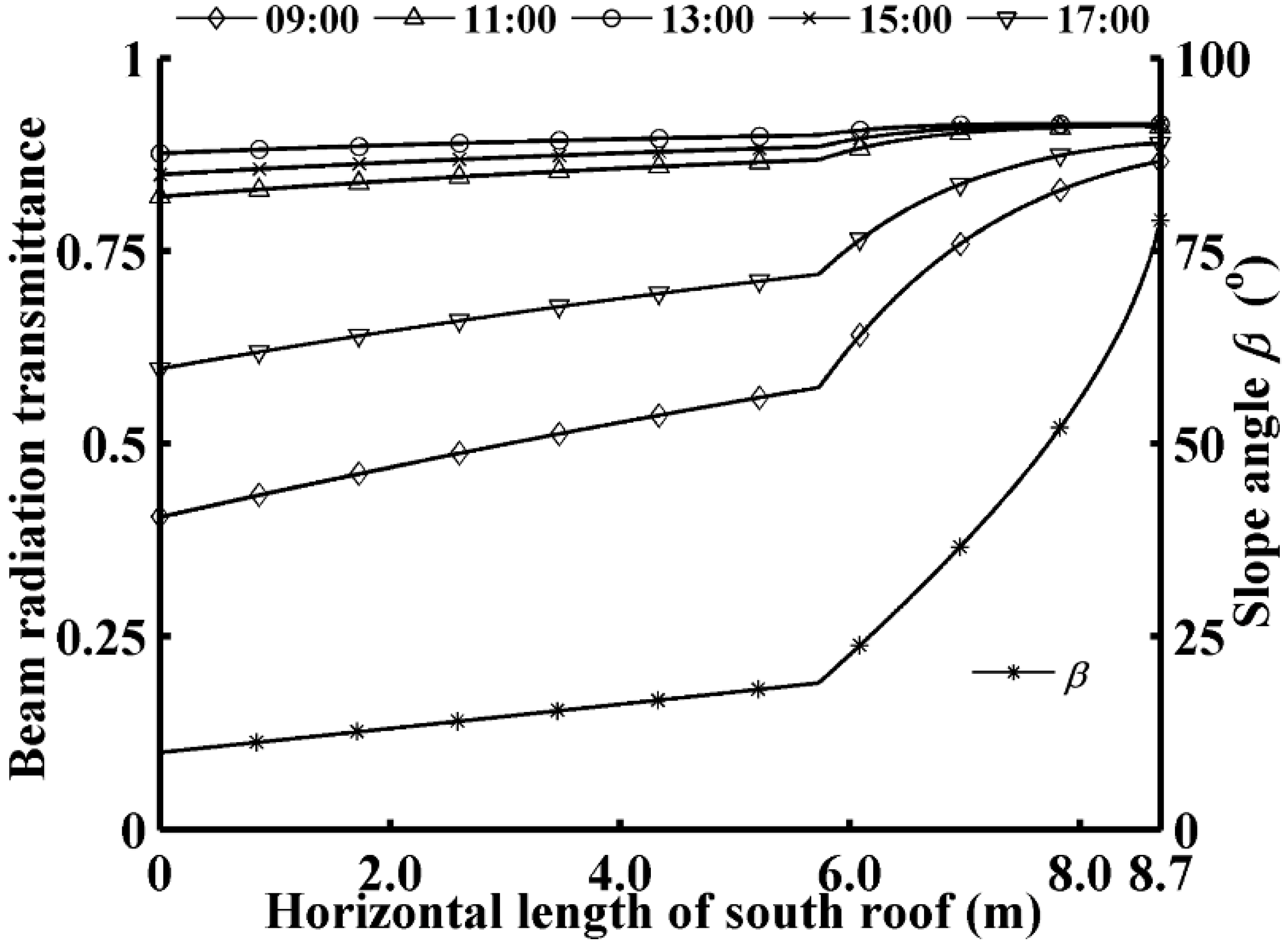
21] investigated the characteristics of the light environment in a sinking solar greenhouse by field measurements. The experimental results indicated that the transmittance of the south roof was minimum in the morning and evening and was maximum at around noon. In Yongning (38°18′ N and 106°15′ E), China, a measurement-base study by Zhang et al. [22] revealed that the solar radiation intensity in the southern part was always higher than that in the northern part of a solar greenhouse. However, the onsite measurement of the environmental factors is time-consuming, and it is unrealizable for a solar greenhouse during the design phase. Several calculation models for solar greenhouses’ light environment have been established to determine the solar radiation capture, allocation, and distribution. To increase greenhouse space utilization, the south roof is curved in most Chinese solar greenhouses [23]. Xuan [24] developed the south roof equation in a solar greenhouse and studied the amount of solar radiation entering the greenhouse through the south roof with different curvatures. The results showed that there was no significant difference in the total entering solar radiation among south roofs with different curvatures. Chen et al. [25] developed a model to calculate the total solar radiation collected by the south roof over the entire typical winter season for off-season vegetable production. In their work, the nonuniform transmittance caused by the varied slope along the south roof was considered. Further, their model was used to determine the optimal orientation of a solar greenhouse. In the study of the solar radiation distribution inside a solar greenhouse, many scholars have simplified both the greenhouse shape and evolution progress of the interior light environment. Considering clear sunny conditions, Han et al. [26] predicted the spatial distribution of the solar radiation within a solar greenhouse by using simulations coded with the VB programming language. To simplify the calculation, the curved south roof was represented by a tilted surface, and an average value of the lighting roof transmittance was adopted; the interior beam radiation and diffuse radiation were estimated based on the shadowing effect of the greenhouse enclosure structure. Ma et al. [27] established a solar greenhouse light environment model that neglects the interior solar radiation reflection, for which an analytical equation of the south roof in a solar greenhouse was developed, and a varying roof transmittance was considered based on an empirical formula deduced from the measured data of a PVC film in Beijing. Yang and Ma [28] investigated the effects of different roof inclination angles on the indoor light environment of solar greenhouse by using the mathematic model established by Ma et al. [27]. Their results suggested that 32° was the optimal inclination angle of roof that was conductive to solar radiation accumulation in a solar greenhouse. Xu et al. [29] established a relatively perfect solar radiation model for solar greenhouse based on the previous models. The model was developed with a consideration of the influence of the sunrays’ incident angle on the beam transmittance and can be applied to sunny weather conditions. Obviously, these models are suitable only for sunny weather in certain regions. Moreover, the simplified interior solar radiation evolution cannot accurately describe the light environment of a solar greenhouse; most important, it is hard to find the lighting environment models that consider the light demands of crops to guide the solar greenhouse planting.
To fill these gaps, a solar greenhouse light environment model suitable for regions at different weather conditions and different geographical latitudes was developed in this study. With this model, the effects of both the shape parameters of the south roof and the optical properties of the lighting materials on the lighting roof transmittance were analyzed quantitatively; the interior solar radiation evolution was accurately described considering the dynamic beam radiation, diffuse radiation, and multi-reflection. Based on the model, we conducted a case study of a solar greenhouse located in the Hexi Corridor, China, where solar greenhouses offer a remarkable opportunity for utilizing solar energy to produce vegetables year round on once unproductive lands. The solar radiation allocation is obtained to determine the solar radiation availability for the north wall and the entire solar greenhouse; the spatial distribution of the solar radiation is obtained to evaluate the light conditions for growing crops in the greenhouse. The model established in this study is expected to guide the optimization of both the light environment regulation and the crop planting for a solar greenhouse, thereby increasing the energy utilization and promoting production efficiency.

2. Establishment of the Solar Greenhouse Light Environment Model

2.1. Curve Equation of the South Roof of a Solar Greenhouse

Figure 2 illustrates the cross-section of a Chinese solar greenhouse and several key joints and geometrical design parameters. The south roof is one of the most crucial parts in a solar greenhouse and is generally composed of the lighting section and the thermal blanket-covered section in practical applications [23]. The shape parameters of the south roof and the optical characteristics of the transparent lighting materials determine the amount of solar energy that a solar greenhouse can capture. In the design of Chinese solar greenhouses, the most common south roof is made by double circular-arcs with different centers and radii, presenting as a smooth curve on the cross-section. The basic design parameters of the south roof are the following:
(1)
the slope angles at the ends of each circular-arc α1, α2, and α3, corresponding to points A, B, and C, respectively. According to the reasonable roof angle method [30] “the slope angle of the south roof is designed so that the incidence angle of sunrays on the roof is less than 40° at solar noon on the winter solstice,” the slope angle α1 at the highest point of the south roof should be more than 10° to maximize light transmission;
(2)
the length of the horizontal projection of the south roof S;
(3)
the height of the solar greenhouse’s ridge H.
Besides, to increase the space usability, the height of the south roof at 1.0 m horizontally from the south basic angle point C must be over 2.0 m. Then, the radii of the two arcs AB and BC will be:
R 1 = S × ( c o s α 2 c o s α 3 ) H × ( s i n α 3 s i n α 2 ) ( s i n α 2 s i n α 1 ) × ( c o s α 2 c o s α 3 ) ( c o s α 1 c o s α 2 ) × ( s i n α 3 s i n α 2 )
R 2 = S × ( c o s α 1 c o s α 2 ) H × ( s i n α 2 s i n α 1 ) ( s i n α 3 s i n α 2 ) × ( c o s α 1 c o s α 2 ) ( c o s α 2 c o s α 3 ) × ( s i n α 2 s i n α 1 )
For the accurate and convenient description of the curve equation of the south roof, the solar greenhouse’s cross-section was expressed in the rectangular coordinate system with the origin at the circle center of the arc AB (Figure 2). Then, the coordinates of the circle center O1 (xO1, yO1) of the circle on which the arc AB was located, the circle center O2 (xO2, yO2) of the circle on which the arc BC was located, and the other key joints A (xA, yA), B (xB, yB), and C (xC, yC) on the south roof can be given as follows:
{ x O 1 = 0 ,   y O 1 = 0 x O 2 = s i n α 2 × ( R 1 R 2 ) ,   y O 2 = c o s α 2 × ( R 1 R 2 ) x A = s i n α 1 × R 1 , y A = c o s α 1 × R 1 x B = s i n α 2 × R 1 , y B = c o s α 2 × R 1 x C = s i n α 3 × R 2 + x 2 , y C = c o s α 3 × R 2 + y 2
respectively. Finally, the curve equation of the south roof in a solar greenhouse is obtained:
{   y = | R 1 2 ( x x O 1 ) 2 | + y O 1   x A x x B   y = | R 2 2 ( x x O 2 ) 2 | + y O 2   x B < x x C
By differentiating the analytical equation of the south roof (Equation (4)), the slope angle β on the curved roof can be calculated as:
{   β = c o t 1 ( y / x )   x A x x B   β = c o t 1 ( ( y y O 2 ) / ( x x O 2 ) )   x B < x x C

2.2. External Solar Radiation Reaching the South Roof of a Solar Greenhouse

The external solar radiation is considered to be composed of three components: the beam radiation, the diffuse radiation, and the solar radiation diffusely reflected from the outside ground. The intensities of the three parts of solar radiation reaching a curved surface depend on the transient solar radiation on the horizontal surface and the slope angle on the curved surface. The instant solar radiation reaching an outside horizontal surface can be obtained by using the clear-sky model on typical clear days [31,32] and the cloud-cover model on cloudy days [33]. The slope angle on the south roof varies along the curved surface according to Equation (5). Therefore, the solar radiation intensity received at the south roof varies over time and is nonuniform along the roof.
The beam radiation has a definable direction, which can be determined by the position of the sun. In this study, the position of the sun relative to the curved south roof can be described in terms of several angles: the solar altitude angle h, solar azimuth angle γ, and slope angle β and azimuth angle γG of the south roof. Here, the solar altitude angle and solar azimuth angle are time-dependent. The dynamic solar motion trajectory changes the incident angle of sunrays relative to the south roof, and thus directly impact the beam radiation intensity received at the roof surface. Along the curved south roof, the dynamic incident angle of sunrays θ can be given as:
θ ( s r ) ( t ) = c o s 1 ( c o s β ( s r ) × s i n h ( t ) + s i n β ( s r ) × c o s h ( t ) × c o s ( γ ( t ) γ G ) )
where the subscripts sr and t indicate that the corresponding term varies along the south roof and over time, respectively. Then, the beam radiation intensity Ib reaching any point on the south roof can be calculated by:
I b ( s r ) ( t ) = I b h ( t ) × c o s θ ( s r ) ( t ) / s i n h ( t )
where Ibh denotes the solar beam radiation intensity reaching an outside horizontal surface in typical clear days.
For the diffuse radiation and the solar radiation reflected from the outside ground, owing to these isotropic properties, the radiation intensities received at the south roof can be derived according to the slope angular relations between the south roof and the horizontal surface. The diffuse radiation intensity Id and ground-reflected radiation intensity Ir on the south roof are given as follows:
I d ( s r ) ( t ) = I d h ( t ) × c o s 2 β ( s r ) 2
I r ( s r ) ( t ) = r o u t × ( I b h ( t ) + I d h ( t ) ) × ( 1 c o s 2 β ( s r ) 2 )
where Idh denotes the diffuse solar radiation reaching an outside horizontal surface in typical clear days, and rout denotes the reflectivity of the outside ground.
In typical clear days, the external solar radiation environment can be obtained according to the clear sky model, with the specific time, and the latitude and longitude of the locations taken as the inputs. Then, Ibh and Idh can be presented as follows:
I b h ( t ) = I 0 × s i n h ( t ) × P c s c   h ( t )
I d h ( t ) = I 0 × s i n h ( t ) × ( 1 P c s c   h ( t ) ) / ( 2 2.8 × ln P )
where I0 is the solar radiation constant and is instantaneously constant with respect to each day of a year, P is the atmosphere transparency coefficient, and the value of the solar altitude angle h is a function of the relevant inputs [31].
In cloudy weather conditions, the cloud-cover model is used to calculate Ibh and Idh as follows:
I b h ( t ) = ( 1 C C / 10 ) × I b h ( t )
I d h ( t ) = C C F × ( I b h ( t ) + I d h ( t ) ) I b h ( t )
where CC is the cloud cover ranging from 0 to 10, and CCF is the function of CC. These values are related to regions and seasons and, for this study, were obtained either from the China Meteorological Administration data center or from the literature [33].
Finally, considering the cross-section of a solar greenhouse (Figure 2), the external cumulative solar radiation reaching the outer surface of the south roof in a day, SRR (MJ), can be obtained by integration as follows:
S R R = t 1 t 2 0 L s r ( I b ( s r ) ( t ) + I d ( s r ) ( t ) + I r ( s r ) ( t ) ) d L   d t
where t1 and t2 denote the starting and ending times of the lighting hours, respectively; Lsr is the length of the south roof, which can be obtained from its curve equation (Equation (4)).

2.3. Solar Radiation Entering a Solar Greenhouse through the South Roof

The solar radiation enters a solar greenhouse only through the lighting section south roof. When reaching the lighting roof, part of the solar radiation is reflected back to the surroundings, and another part enters into the solar greenhouse through the transparent roofing materials and is used for lighting and heating of the greenhouse, providing suitable light and thermal environments for crops. In the Chinese solar greenhouse, the amount of entering solar radiation energy is greatly influenced by the transmittance of the transparent materials, which is a function of the sunrays’ incident angle and the material’s optical parameters. According to the Fresnel and Bouguer’s law, the transmittance τ of a lighting roof is [31]:
τ = 1 2 ( 1 P 1 + P + 1 P 1 + P )
where P represents the perpendicular component of solar radiation and can be calculated from Equation (16); P represents the parallel component and can be calculated from Equation (17):
P ( s r ) ( t ) = s i n 2 ( θ z ( s r ) ( t ) θ ( s r ) ( t ) ) s i n 2 ( θ z ( s r ) ( t ) + θ ( s r ) ( t ) )
P ( s r ) ( t ) = t a n 2 ( θ z ( s r ) ( t ) θ ( s r ) ( t ) ) t a n 2 ( θ z ( s r ) ( t ) + θ ( s r ) ( t ) )
where θz denotes the angle of refraction and is related to the sunrays’ incident angle θ and the medium’s refractive index Z as follows:
θ z ( s r ) ( t ) = s i n 1 ( s i n θ ( s r ) ( t ) / Z )
When considering the beam radiation, the sunrays’ incident angle on the curved lighting roof varies with the slope angle and time (Equation (6)). Hence, the lighting material’s transmittance for beam radiation τb is different at different positions and times. In previous studies on the light environment inside solar greenhouses, most scholars used an average value of the transparent roof transmittance for beam radiation, with the curved south roof represented as a tilted surface with a constant equivalent slope angle [26,34]. In this study, we consider the south roof of a solar greenhouse in Jiuquan city of the Hexi Corridor (98°30′ E, 39°42′ N) with a layer of clear polyolefin (PO) film as the lighting material. The influence of the varying slope angle on the beam radiation transmittance values along the roof curve can be calculated using Equations (6) and (15)–(18). Here, the refractive index Z for PO film is taken as 1.535 [35]. The calculation is conducted in the winter solstice (December 22), and the result is given in Figure 3. As can be seen from Figure 3, the slope angle increases along the roof curve from the highest point A to the south basic angle point C. The transmittance of the PO film varies with the slope angle, and its value remains constant near point C. It can be found that the transmittance differences along the curved roof are approximately 113.8, 11.2, 4.4, 7.7, and 48.9% at 09:00, 11:00, 13:00, 15:00, and 17:00, respectively. It should be noted that adopting the average transmittances of the equivalent tilting roof has a small influence on the total amount of the entering beam radiation through the roof, but the light environment inside a solar greenhouse depends not only on the amount of entering solar radiation but also on the solar radiation distribution inside the greenhouse. As mentioned above, the beam radiation has a definable direction, so each incidence point on the lighting roof with nonuniform beam incident intensity and nonuniform transmittance corresponds to different receiving points on the internal surfaces of the greenhouse. This becomes particularly important for the energy balance of the solar greenhouse system, the different transmittances along the lighting roof determines the allocation of the entering solar beam radiation energy.
The incident angular distributions of the diffuse and ground reflective radiations characterized by isotropy are generally unknown. Therefore, an equivalent transmittance τd is set for the isotropic radiation as it does for the beam radiation incident at an angle of 60° [31]. Finally, the intensity of solar radiation Ien entering the solar greenhouse through the lighting roof is the sum of the beam radiation intensity Iben and the diffuse/reflective radiation intensity Iden as follows:
I e n ( s r ) ( t ) = I b e n ( s r ) ( t ) + I d e n ( s r ) ( t )
where:
I b e n ( s r ) ( t ) = I b ( s r ) ( t ) × τ b ( s r ) ( t )
I d e n ( s r ) ( t ) = I d ( s r ) ( t ) × τ d
Similarly, the cumulative solar radiation entering a solar greenhouse through the south roof per day, SRE (MJ), can be obtained by integration with respect to the length of the lighting section Llr:
S R E = t 1 t 2 0 L l r I e n ( s r ) ( t ) d L   d t

2.4. Solar Radiation Evolution inside a Solar Greenhouse

The solar radiation distribution inside a solar greenhouse has two main aspects: the solar radiation allocation on the internal surfaces of the greenhouse and the spatial distribution of the solar radiation in the greenhouse. The radiation energy entering the solar greenhouse, including the beam radiation and diffuse radiation, falls on various surfaces: the inner surfaces of the greenhouse envelope, the ground surface, and the crop canopy surface. Unlike conventional greenhouses, which allow the solar radiation falling on the envelope’s inner surfaces to be transmitted outside the greenhouse, resulting in a decrease in the greenhouse’s solar radiation availability. The Chinese solar greenhouse has a unique opaque envelope that is designed for maximizing the solar energy available for heating. The most critical components are the north wall and the ground under the solar greenhouse, which functions as a passive regenerator with high thermal capacity. The solar radiation falling on the north wall and ground is absorbed and stored as heat, and then released to warm the inside air during the nighttime. This enables the agricultural facility to rely entirely on solar energy to provide the desired thermal environments for crops in cold seasons. Therefore, it is of considerable importance to determine the solar radiation allocation of a given solar greenhouse type, with the aim of optimizing the design parameters, thus improving the thermal environment.
Moreover, considering the crop planting, the total solar radiation received at the canopy surface and the solar radiation distribution are the main factors affecting the plant’s photosynthesis and transpiration [36,37]. Because the canopy height varies throughout the course of the crop growth and development, the solar radiation received at the canopy surface is affected not only by the solar radiation entered through the south roof, but also the canopy surface’s location within the greenhouse. Therefore, the precise spatial distribution of the solar radiation in a solar greenhouse can be applied to provide a desirable light environment for a specific crop during the different growth stage, guiding the optimization of the solar greenhouse planting.

2.4.1. Evolution of Beam Radiation inside the Solar Greenhouse

Consider the lighting roof as a radiation light-source. The light-source emits beam radiation and diffuse radiation into the solar greenhouse. The beam portion reaches the internal surfaces along the sunray’s path. In the rectangular coordinate system established in Section 2.1, the path equation of a sunray going through an arbitrary point p inside the greenhouse can be expressed as follows:
y = k ( t ) × ( x x p ) + y p
where k denotes the slope of the sunray and can be expressed as k(t) = tan h(t)/cos (γ(t)γG) in the greenhouse’s cross-section; xp and yp denote the coordinates of the arbitrary point p.
By solving the sunray’s path equation (Equation (23)) and the curve equation of the south roof (Equation (4)) simultaneously, the corresponding incidence point of an interior receiving point can be found along the south roof. If the location of the corresponding incidence point is outside the interval of the lighting section curve, the beam radiation does not fall on the considered point; thus, shadowing occurs. By contrast, once the point receives beam radiation, the beam radiation intensity Ibin can be calculated based on the transmitted beam radiation intensity at the corresponding incidence point and the relation between the slope angles of the surface elements representing these two points. Taking a point on the north wall’s inner surface as an example, Ibin can be expressed as:
I b i n ( t ) = I b e n ( s r ) ( t ) × s i n ( β ( s r ) + t a n 1 k ( t ) ) s i n ( 180 t a n 1 k ( t ) β w )
where βw is the tilting angle of the north wall’s inner surface.
From experiences with many Chinese solar greenhouses designs, it is suggested that, when the lowest monthly average outside temperature is less than 0 °C, the north wall should receive as much solar beam radiation as possible between 10:00 and 14:00 each day, to ensure sufficient heat storage [38]. From Figure 2, it is found that the shadow falling on the greenhouse’s internal surface is mainly caused by the north roof and the thermal blanket-covered section of the south roof. In a practical application, the length of the opaque north roof is fixed, while the length of the thermal blanket-covered roof is changed: the blanket can be opened and closed. The opening and closing time depend upon both the external temperature and solar radiation conditions [25]. During the lighting hours, given that the rolled-up thermal blanket occupies a certain area, 0.8 m horizontally on the top of the south roof are set aside in accordance with the common solar greenhouse design standard [38]. Therefore, the shadow region, which changes with time, can be determined by tracing the impact point of the sunray going through the moving point at the end of the thermal blanket. Then, the dynamic light region on the north wall that can directly receive the beam radiation can be obtained.

2.4.2. Evolution of Diffuse Radiation inside the Solar Greenhouse

The isotropic diffuse portion emitted from the lighting roof consists of the transmitted diffuse solar radiation and the transmitted ground-reflected solar radiation. Its scattering can be quantitatively described by the radiation angular distribution. When the diffuse radiation intensity of the light source is obtained by Equation (21), the diffuse radiation received at any point inside the greenhouse will depend upon the fraction of diffuse radiation scattered by the lighting roof into the point. Therefore, the radiation angular distribution coefficient F, which is a function of the characteristic size and location of the studied point relative to the diffuse radiation source, can be defined [39]; it gives the percentage of the diffuse radiation received by an element from another to the total diffuse radiation emitted from the latter element to the surroundings. Within the two-dimensional greenhouse cross-section (Figure 2), the radiation angular distribution coefficient from element e1 to element e2 can be expressed as follows:
F e 1 e 2 = c o s δ e 1 × c o s δ e 2 2 × l d e 2
where δ e 1 denotes the angle between the line connecting these two elements and the normal to the element e1, δ e 2 denotes the angle between the connection line and the normal to the element e2, l denotes the length of the connection line, and e denotes the characteristic size of the calculating element.
Then the radiation angular distribution coefficient from the lighting roof towards an interior point p can be obtained by integration as follows:
F l r p = 1 L l r × 0 L l r F e l r e p   d e l r
Therefore, the diffuse radiation intensity received at point p can be expressed as:
I d i n ( t ) = F l r p × 1 e p × 0 L l r I d e n ( s r ) ( t )   d L
At this stage, the initial distribution of the solar radiation inside a solar greenhouse can be determined. The radiation intensity at an arbitrary point is the sum of the beam radiation intensity Ibin and the diffuse radiation intensity Idin received at the point.

2.4.3. Evolution of Multi-Reflective Radiation inside the Solar Greenhouse

Besides the solar radiation absorbed by the internal surfaces of the greenhouse, other solar radiation components falling on these surfaces are reflected back to the surroundings [39]. The amount of radiation reflected is linearly proportional to the surface reflectance, which mainly depends upon the surface color. The reflective radiations are composed of the beam and diffuse radiations entering the greenhouse through the lighting roof, with the beam radiation being dominant. However, the reflective radiation emitted by each surface is scattered equally in all directions owing to the roughness of surfaces of the north wall, north roof, ground, and leaves. Therefore, the reflective radiation will not go back the way it came, and the total radiation reflected from a surface will be allocated to other surfaces by angular distribution coefficients for radiation. Furthermore, when the reflective radiation reaches another surface, it will be absorbed and reflected. The above process repeats many times in the solar greenhouse system, and thus it is very complicated to estimate the amount of reflective radiation among the various surfaces. During the multiple diffuse reflections, the reflective radiations falling on the lighting roof are in part transmitted outside and lost because they are short-wave radiation, while the reflective radiations falling on the surfaces of the north wall and the ground are absorbed, and converted and stored as heat energy, and finally used for the greenhouse’s nocturnal heating. Therefore, the interior multi-reflection phenomenon has a significant impact on the energy balance of the solar greenhouse system and ultimately influences the greenhouse’s thermal environment.
In previous studies, the multi-reflective radiation has not been considered, and the solar energy availability of the greenhouse has been underrated. In our study, a computer program was developed in MATLAB to compute the multi-reflective radiation in the solar greenhouse and evaluate the solar greenhouse light environment as accurately as possible. The reflection process occurring in the greenhouse system was reconstructed over multiple iterations by using the radiation angular distribution coefficient of several surfaces. Taking the north wall as an example, the instantaneous total reflective radiation reaching the wall’s inner surface, REw at the i-th iteration can be given as:
R E w , i ( t ) = j = 1 5 ( R E j ,   i 1 ( t ) × r j × F j w )   i = 2 ,   3 ,   4 , R E j , 1 ( t ) = 0 L j ( I b i n ( j ) ( t ) + I d i n ( j ) ( t ) ) d L
where j denotes the j-th internal surface, rj denotes the surface reflectance, and Fj−w denotes the radiation angular distribution coefficient from the j-th surface to the wall surface and is constant for a given solar greenhouse.
When the reflective radiation intensity reaching the internal surface is lower than 0.01 W/m2, the impact of the next several reflections on the solar radiation allocation in the greenhouse is considered negligible. Then, the calculation steps for the diffuse radiation distribution in Section 2.4.2 are repeated to scatter the reaching reflective radiation. Considering each internal surface as a radiation light-source, the cumulative reflective radiation intensity Irin at an interior arbitrary point p can be calculated using the light-source intensity and the radiation angular distribution coefficient from the light-source to the point:
I r i n ( t ) = 1 e p × i = 1 N j = 1 5 ( R E j , i ( t ) × r j × F j p )
where N is the total number of solar radiation reflections obtained from the iteration operation.

2.4.4. Solar Radiation Distribution and Solar Radiation Availability in the Solar Greenhouse

At this stage, in the solar greenhouse, the final solar radiation intensity at an arbitrary point can be expressed as:
I i n ( t ) = I b i n ( t ) + I d i n ( t ) + I r i n ( t )
Accordingly, the cumulative solar radiation SRA (MJ) allocated to each internal surface during a day can be calculated by:
S R A j = t 1 t 2 0 L j I i n ( t ) × ρ j   d L   d t
where Lj denotes the length of the j-th surface in the greenhouse cross-section; ρ denotes the surface solar radiation transmittance τ of the inner surface of the lighting roof and is equal to the surface solar radiation absorbance for other opaque internal surfaces.
For the spatial distribution of the solar radiation in the solar greenhouse, several horizontal surfaces with different heights are considered in the greenhouse space to simulate the canopy height variations during the crop growth and development. Subsequently, the solar beam radiation, diffuse radiation, and reflective radiation at each point on these horizontal surfaces can be calculated using the abovementioned calculation program. Finally, the time evolution of the solar radiation’s spatial distribution can be obtained. Therefore, in a given solar greenhouse, both the total solar radiation and the solar radiation distribution received at the crop canopy for a specific crop during a specific growth stage can be determined quantitatively. To further guide the crop planting, the solar radiation intensity can be converted into illuminance as follows [40]:
L U X i n ( t ) = 0.009715 × I i n ( t ) 2 + 100.466 × I i n ( t ) 402.591
To assess the solar radiation availability in a solar greenhouse, especially at the north wall, which plays an important role in increasing the inside air temperature, two evaluation parameters are proposed for a one-meter length along the east-west orientation: the solar radiation availability for the north wall AVAw (MJ/m) and the total solar radiation availability of the solar greenhouse AVA (MJ/m):
A V A w = S R A w
A V A = S R A w + S R A n r + S R A g + S R A c + S R A t b
where w, nr, g, c, and tb denote the north wall, north roof, ground, canopy, and thermal blanket-covered south roof, respectively. In the following sections, when considering the solar radiation allocation, the ground and crop canopy are analyzed as a whole because, in general, they have the same solar radiation absorbance with a value of 0.9 [33,41].

3. Experimental Validation of the Solar Greenhouse Light Environment Model

For the validation of the reliability of the established solar greenhouse light environment model, both onsite field measurements and model simulations were conducted in a Chinese solar greenhouse of the Hexi Corridor, which was constructed at the national Gobi ecological agricultural industry park in Dongdong Village, Jiuquan City, Gansu Province, China (98°30′ E, 39°42′ N, altitude 1666 m). The experimental site is rich in solar radiation with cumulative solar radiation of >6.1 GJ/m2·yr−1 and 2800–3300 h of annual sunshine, which ensures a sufficient energy-supply for the operation of solar greenhouses [8]. The experimental solar greenhouse was built in 2019, and a middle-fruit-type tomato crop growing started in September 2019. The greenhouse was constructed facing the due south (
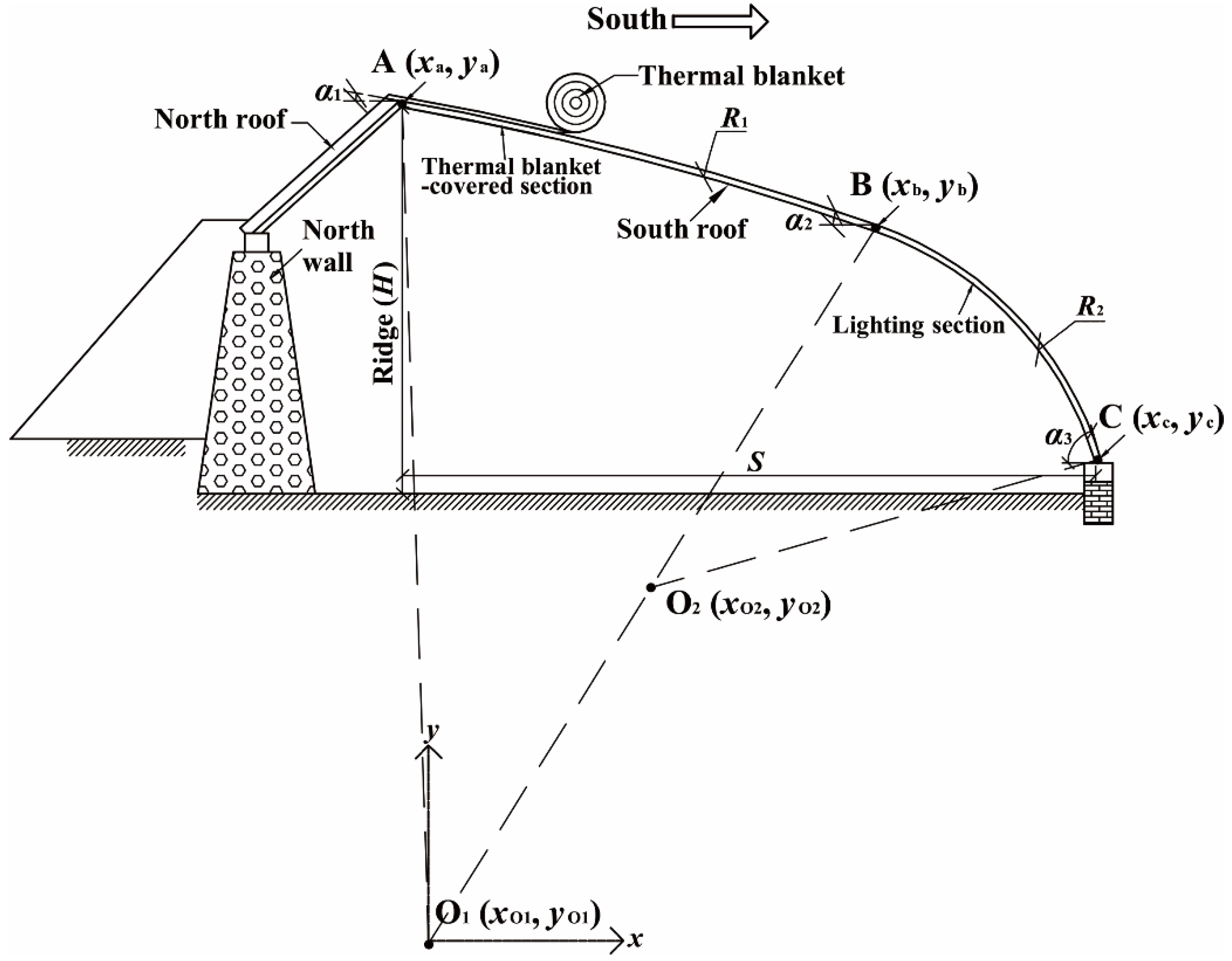
γG = 0°) and was 80 m long with an east-west orientation. It had a span of 10 m with the horizontal projection of the south roof (S) occupying 8.7 m and had a ridge height H of 4.9 m. The south roof was composed of two circular-arcs. The slope angles α1, α2, and α3 at end points of each circular-arc were 10°, 19°, and 79°, respectively. A layer of clear polyolefin (PO) film was used as the roof lighting material. The north roof had a slope angle of 42°; it was constructed using steel sandwich panels with a 0.15 m-thick layer of polystyrene in the middle, and its inner surface was blackwashed. The north wall was a gravel-layered wall with a vertical height of 3.3 m and a slope angle of 82°. This type of north wall is specifically designed for the Gobi region, and can efficiently improve the greenhouse temperature environment with its good heat storage/release performance [
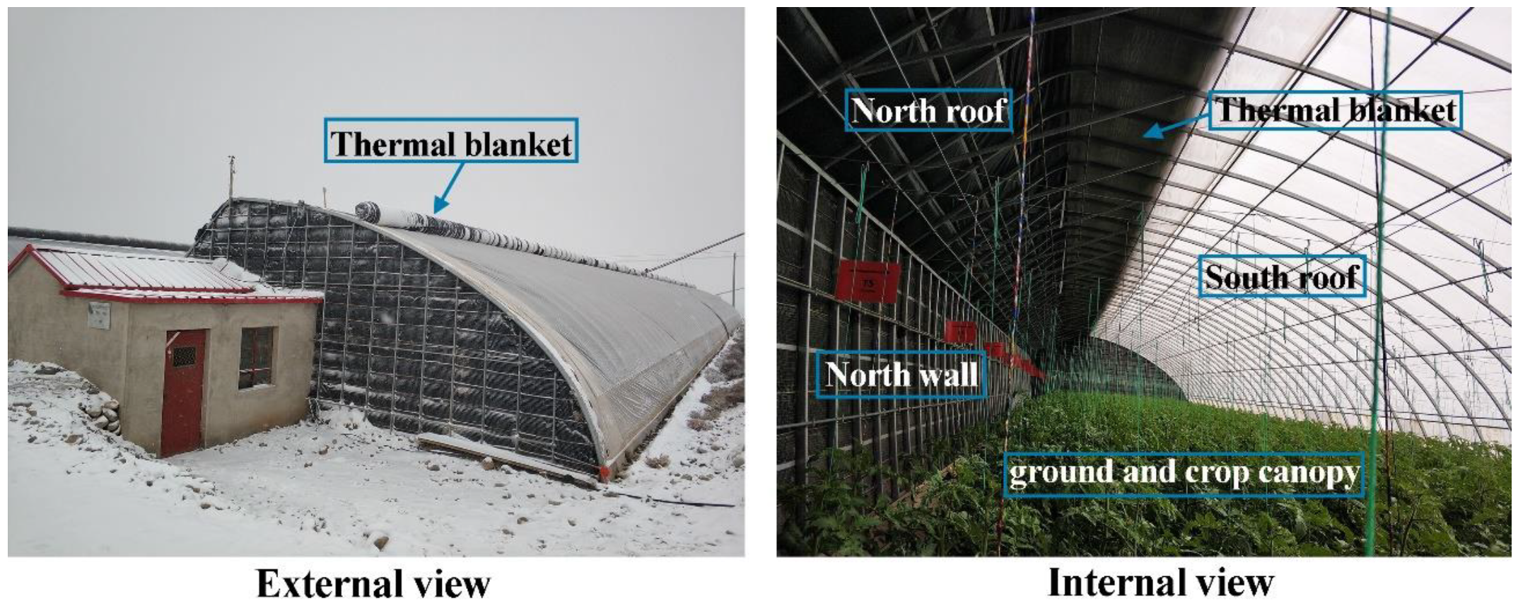
14]. The internal and external views of the experimental greenhouse are depicted in Figure 4.
We now consider the optical properties of the building materials that affect the solar radiation evolution inside a solar greenhouse. In the experimental solar greenhouse, regarding the inner surfaces of the north wall and north roof were covered with black light-absorbing film; the ground was moist dark-colored cultural substrates, which made of blend of pumice, expanded shale, compost, and sand; on the plant canopy layer, nearly 10% of the solar radiation was reflected, and the rest was absorbed and used for plant transpiration and photosynthesis, the following surface solar radiation absorbances were adopted: ρw = ρnr = ρg = ρc = 0.9 [33,41].
For the roof lighting material, the solar radiation absorbance of PO film was zero due to its small thickness (0.001 m); the beam radiation transmittance τb on the lighting roof was not uniform and varied with time and the diffuse radiation transmittance τd was constant according to these transmission characteristics. During the validation, τb and τd of PO film could be calculated based on the material’s refractive index (Z taken as 1.535 [35]) by using Equations (15)–(18). Input parameters used in the model validation are shown in Table 1.
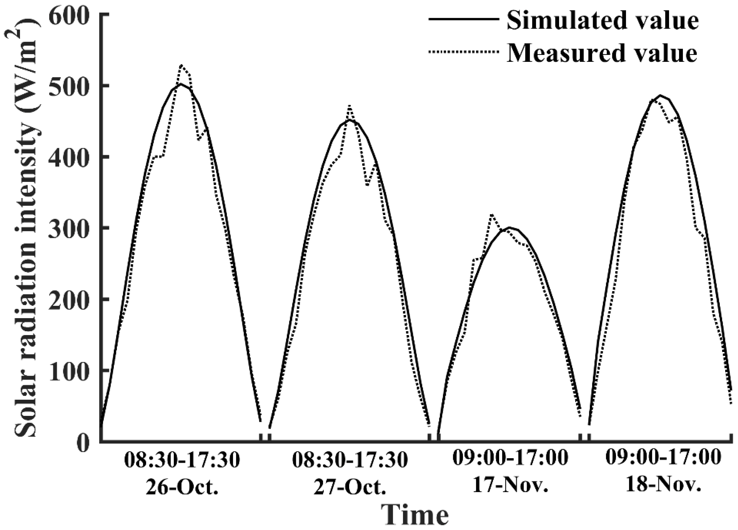
The solar radiation inside the greenhouse was measured and recorded using a PC-2B solar radiation recorder (Jinzhou Sunshine, Jinzhou, China), which has an accuracy of ±0.5%. The measurement point was set at a height of 1.3 m at the center of the greenhouse. The data were recorded at 30 min intervals, and the field measurement was performed from 1 October 2019 to 31 December 2019. During the validation, the measured and simulated data were compared under both clear sunny conditions and cloudy conditions. From the outdoor meteorological data collected from the China Meteorological Administration data center, it was found that 26 October had a typical sunny weather with a zero cloud cover CC throughout the day and that 27 October had a slightly cloudy weather with a CC equal to 1; then, a commonly cloudy weather with a CC of 7 was observed in 17 November, which was followed by a slightly cloudy day with a CC of 2. These four days have suitable weather conditions to validate the established light environment model.
Based on the design parameters of the experimental greenhouse and the weather data of the selected days, the solar greenhouse light environment model was implemented within the MATLAB environment. In the simulation period, the lowest daily average temperature on 26 and 27 October was above zero. Therefore, the thermal blanket was kept rolled-up, and the horizontal length of the thermal blanket-covered section was kept at 0.8 m during these days. The lowest daily average temperature on 17 and 18 November was −9.8 °C, and the opening and closing times of thermal blanket in these days were obtained using a mathematic model established by Chen et al. [25], with the lighting times from 09:30 to 17:00; the moving end finally stopped at a point with the horizontal length of 0.8 m. Using Equation (24), (27), and (29), the time-dependent beam radiation, diffuse radiation, and reflective radiation at the measured point (the center of the greenhouse at a height of 1.3 m) were calculated, respectively. The summation of these three solar radiations (Equation (30)) was taken as the simulated results of the solar radiation intensity at the measurement point.
A comparison of the simulation and measurement results of the dynamic solar radiation intensity in the experimental greenhouse is presented in Figure 5. The figure shows that the model captured the key solar radiation variations. Under the typical sunny condition (26 October), it was observed that the unregular peaks appeared around the midday on the measured solar radiation variation curve when compared with the simulated solar radiation variation curve, which were caused by the shading of the roof frame. Furthermore, the mean percentage error (MPE), mean bias error (MBE), root mean square error (RMSE), and determination coefficient (R2) were calculated to validate the established model. In clear sunny weather, the MPE, MBE, and RMSE were 1.67%, 13.59 W/m2, and 28.09 W/m2, respectively; in cloudy weather, the MPE, MBE, and RMSE were 10.30%, 17.75 W/m2, and 28.53 W/m2, respectively. Overall, the determination coefficient R2 for this model was 0.9756. These results validate the established solar greenhouse light environment model. Han et al. [26] established an estimation model of solar radiation within solar greenhouses considering only the evolution of the beam and diffuse parts of the solar radiation entering a solar greenhouse and neglecting the interior reflection. They reported that, in clear sunny weather condition, the model had an MPE, MBE, and R2 of 8.8%, 35 W/m2, 0.6112, respectively. The solar radiation model in solar greenhouse established by Xu et al. [29] took the influence of the sunrays’ incident angle on the beam transmittance into account. The model had an MBE of 68.48 W/m2, and an RMBE of 79.18 W/m2.

4. Model Applications in Solar Greenhouse Planting and Light Environment Regulation

4.1. Seasonal Spatial Distribution of the Solar Radiation in the Solar Greenhouse That Determines the Greenhouse Planting

Because there is no auxiliary lighting and heating, solar greenhouse cultivation still partially depends on the natural environment. In particular, the seasonal variation of the climate conditions significantly influences the crop planting in the solar greenhouse. Light in a solar greenhouse is weaker than on the outside and is determined by the periodic external solar radiation variations with a cycle of a year; it is also affected by the greenhouse envelope, which can be reflected by the spatial distribution of the solar radiation.
The calculation model established in this study can be applied to simulate and predict the light environment of a solar greenhouse accurately and conveniently. In this section, a case study based on the established solar greenhouse light environment model is conducted to investigate the annual dynamic spatial distribution of the solar radiation of a solar greenhouse in Jiuquan city, with the aim of guiding the planning of crops planting and thereby exploiting the maximum possible entering solar energy. The studied solar greenhouse has the same design parameters as the experimental solar greenhouse described in 
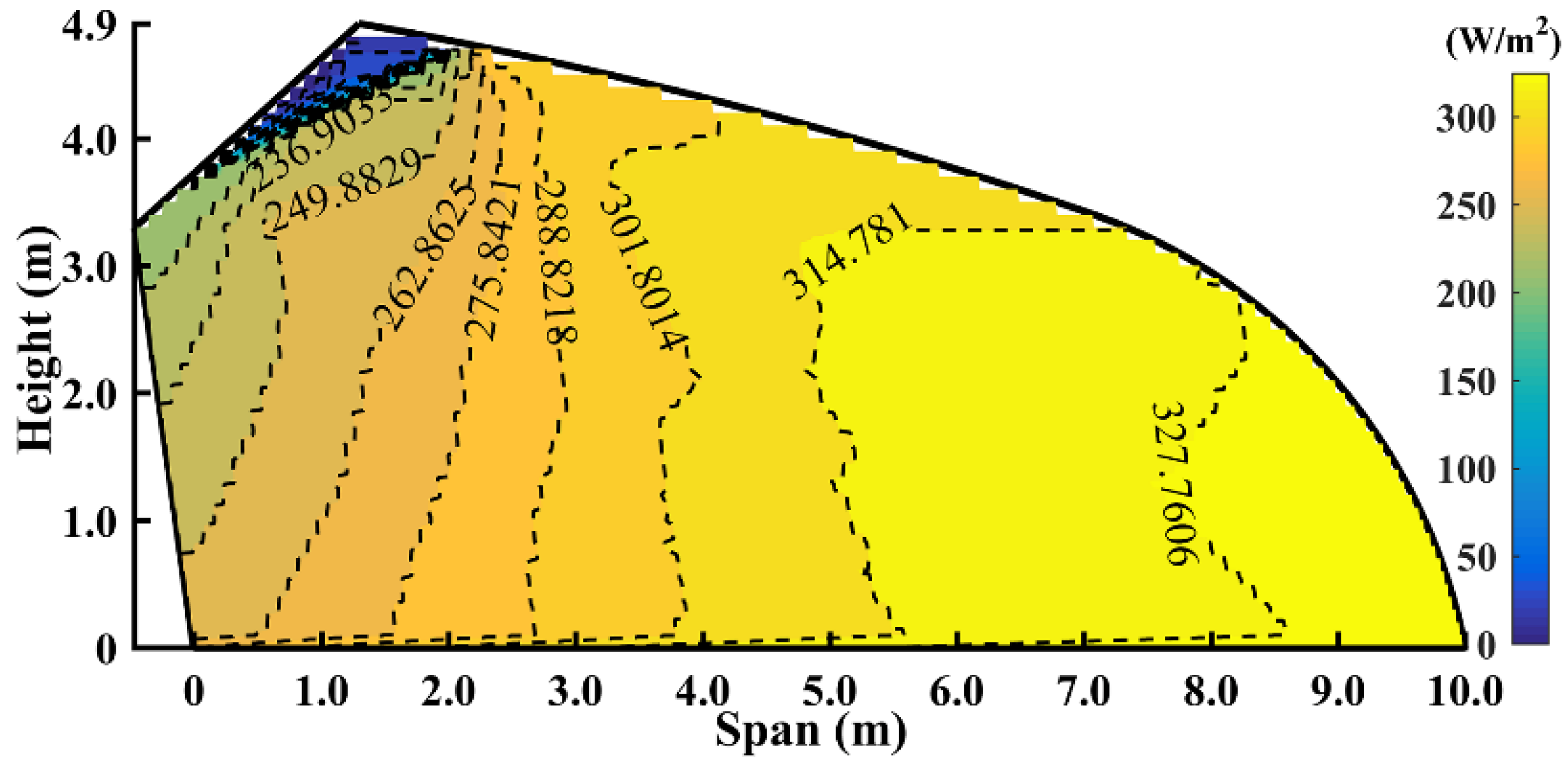
Section 3. Four typical solar terms, namely the vernal equinox (20 March), summer solstice (21 June), autumn equinox (23 September), and winter solstice (22 December), are selected to represent the external solar radiation variation in a year. The summer solstice has the maximum daily total solar radiation of a year, while the winter solstice has the minimum daily total solar radiation in the northern hemisphere. The simulated spatial distribution of the average solar radiation intensity during the lighting hours for the studied solar greenhouse is presented in Figure 6.
It can be observed that a shadow exists in the region near the north roof and north wall for all four solar terms; the largest and smallest shadow areas appeared in the summer and winter solstices, respectively. The shadow results from the opaque north roof and the thermal blanket covering the south roof, both of which act as shields against solar beam radiation. The change in the shadow area is expected owing to the solar altitude variation in the northern hemisphere. In the summer solstice, on the 2.0 m-height horizontal plane representing the commonly highest crop canopy, the projected shadow occupies a width of 1.6 m in which the average solar radiation intensity is only 38.42 W/m2 (3472 lux), which is significantly lower than that in the region with no shadow and is particularly disadvantageous for crops growth. For the region with no shadow, a high-intensity light region appears near the south roof with a solar radiation intensity reaching 482.12, 544.22, 433.12, and 325.93 W/m2, in the four solar terms from spring to winter, respectively. Then, the solar radiation intensity distributions exhibit an obviously decrease from the greenhouse center to the side near the north wall on the cross-section, falling to 410.28, 520.16, 390.10, and 218.16 W/m2, respectively. Along the vertical direction, a small solar radiation intensity variation in vernal equinox, summer solstice, and autumn equinox are observed; whereas in the winter solstice, a relatively large variation is observed within an approximately 2.5 m from the north wall; in this case, the solar radiation in the upper space is 53.9 W/m2 lower than that in the bottom on average. This is mainly caused by the nonuniform beam radiation intensity and beam transmittance along the south roof.
After converting the solar radiation intensity into illuminance using Equation (32), the average illuminance within the space required for crops growth is found to range between 42,000 and 50,000 lux in the entire greenhouse span in the vernal equinox, between 54,000 and 57,200 lux within 8.0 m from the bottom of the south roof in the summer solstice, between 40,000 and 45,000 lux and 22,000 and 33,500 lux in the entire span in the autumn equinox and winter solstice, respectively.
Every crop has an appropriate illuminance range: the minimum value is defined as light compensation point and the maximum is light saturation point. When the light intensity is lower than the light compensation point, the crop photosynthesis is weak and the organics could hardly be accumulated within the crop body. When the light intensity is higher than the light saturation point, it will destroy the chlorophyll and chloroplast membrane and will result in photoinhibition [42]. When the light intensity is within the appropriate range that the crop demands, crop can growths healthily. For a given solar greenhouse, its annual spatial dynamics of solar radiation can be used to determine the reasonable crop varieties and planting seasons based on the lighting demands of different crops, thereby optimizing the solar greenhouse planting pattern and enhancing the production efficiency. Regarding the studied solar greenhouse located in the Hexi corridor, some recommendations can be made for its crop planting: the light-demanding crops requiring an illuminance in the range of 42,000–57,200 lux, such as tomatoes or watermelons [43,44], can be planted in spring and summer; the low light-tolerating crops that require an illuminance in the range of 25,000–40,000 lux, such as cucumbers or peppers can be planted in autumn and winters [45,46]; and the crops that require a moderate illuminance and a long sunshine exposure, such as zucchinis that need 40,000–50,000 lux of illuminance and 8–11 h of light per day [47], should be planted in spring and autumn. Additionally, when the solar greenhouse is utilized in summer, some supplementary lighting measures should be taken to improve the light environment in the low light region near the north wall.

4.2. Optimizing the Regulation of the Solar Greenhouse Light Environment

4.2.1. Effect of the Interior Multi-Reflection on the Light Environment of the Solar Greenhouse

The purpose of this section is to determine the effect of the interior multi-reflection on the solar radiation allocation and spatial distribution in the solar greenhouse quantitatively by using the established model. Because the winter solstice (December 22) has the minimum total solar daily radiation of a year in the northern hemisphere, the interior light environment of this day can be used to effectively and objectively evaluate the light performance of a solar greenhouse. Therefore, the model simulations would be performed with and without multi-reflection in the studied solar greenhouse in Jiuquan on a sunny winter solstice day (CC = 0). The adopted surface solar radiation absorbances are ρw = ρnr = ρg = 0.9. The opening time of the thermal blanket is 1.1 h after the sunrise, and the closing time is 0.5 h before the sunset, during which the horizontal length of the thermal blanket covered-south roof is kept at 0.8 m.
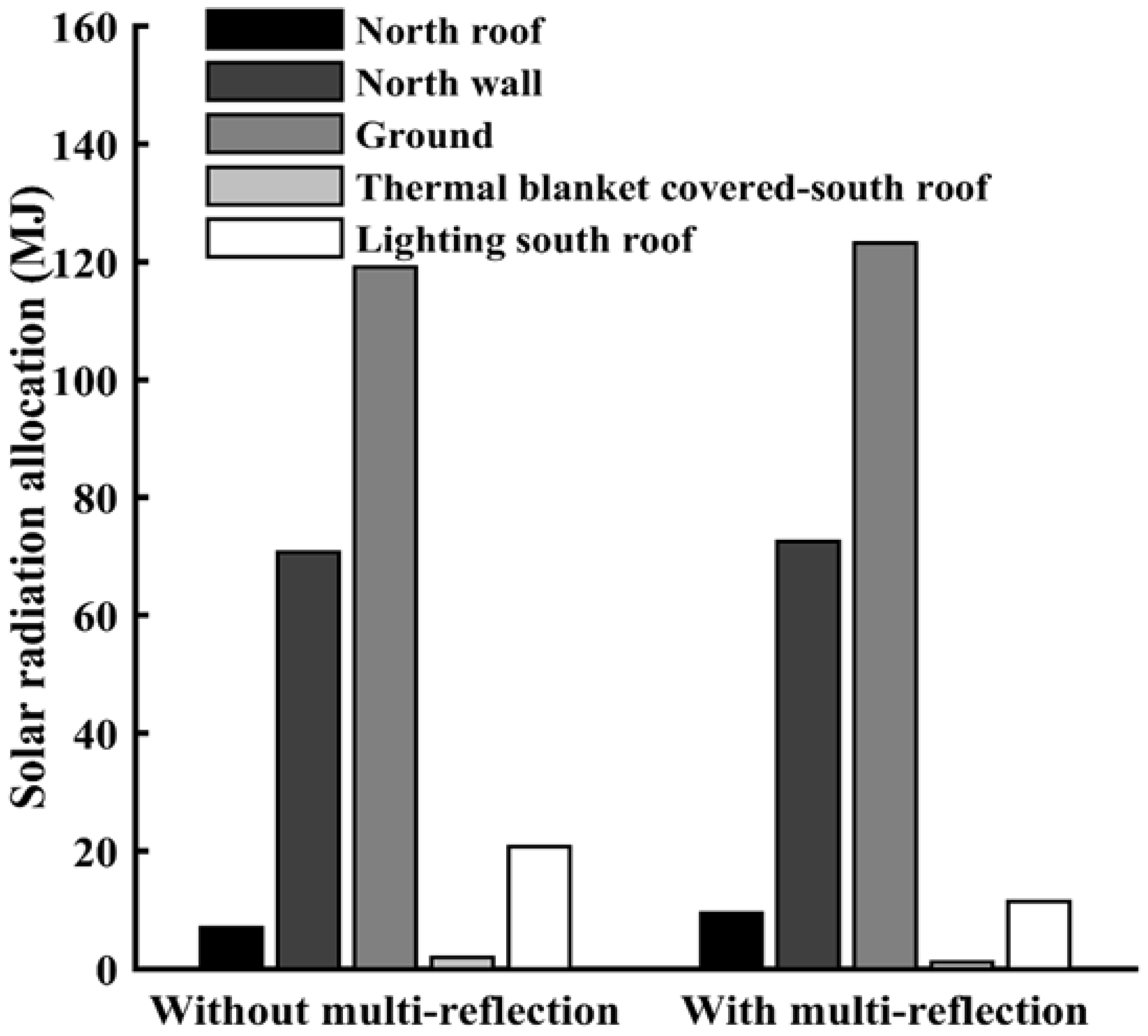
A comparison of the solar energy allocation in the solar greenhouse with the interior multi-reflection neglected and considered is presented in Figure 7. As already reported in Section 2.3, the cumulative solar radiations entering the greenhouse through the south roof for these two cases are equal in one day: 223.93 MJ for a one-meter length along the east-west orientation, according to Equation (22). From Figure 7, it is observed that, during the lighting hours (09:50–17:20), the cumulative solar radiation (SRA) allocated to the inner surfaces of the north roof, north wall, ground, and south roof are 7.00, 70.72, 119.08, and 22.79 MJ, respectively when neglecting reflection. However, when considering multi-reflection, those values are 9.44, 72.52, 123.19, and 12.60 MJ, respectively. Except for that of the south roof, all SRAs are larger than in the first case and increase by 34.9% for the north roof, 2.5% for the north wall, and 3.5% for the ground. The south roof is divided into the lighting section and the thermal blanket-covered section, in which the diffuse part and reflective part of the solar radiations falling on the thermal blanket-covered section are either reflected back to the interior or absorbed by the blanket close to the transparent lighting film, without being transmitted outsides and directly lost.
Therefore, solar radiation energy is lost through the south roof only in the lighting section, with daily cumulative values of 20.77 and 11.47 MJ with and without multi-reflection, respectively; thus, the interior multi-reflection results in a 44.8% lower daily cumulative value. Consequently, the total solar radiation availability of the solar greenhouse can be obtained by Equation (34), which gives 206.27 and 196.81 MJ/m with and without multi-reflection, respectively.
It can be determined that the total solar radiation availability of the solar greenhouse is underrated when neglecting the effects of the interior multi-reflection, which will result in increased energy consumption budget and thus unnecessary waste. Therefore, it is strongly recommended that the interior solar radiation multi-reflection be considered for the solar greenhouse design.
The spatial distributions of the solar radiation on the solar greenhouse cross-section obtained with and without interior solar radiation multi-reflection are shown in Figure 8, with the average solar radiation intensity distribution on each horizontal plane with a height of 0, 1.0, 2.0, and 3.0 m presented. With multi-reflection, the solar radiation intensity along the horizontal planes comprising the solar greenhouse space is higher; the most obvious difference between the two cases is observed in the 0 m-height plane, i.e., the ground surface. The average solar radiation intensity differences between the two cases on the four planes with the heights of 0, 1.0, 2.0, and 3.0 m are 10.28, 2.96, 3.02, and 3.06 W/m2, respectively, and the maximum solar radiation intensity differences are 11.91, 3.39, 3.76, and 4.80 W/m2, respectively, which appear approximately 1.5 m from the north wall’s inner surface. It appears that the multi-reflection slightly alleviates the low light environment in the north-side region of the greenhouse. However, it must be noted that, in the studied solar greenhouse, both the north wall and north roof have a black colored inner surface (Figure 4), so the north wall and north roof have a low reflectance: rw = rnr = 0.1; therefore, the reflection within the greenhouse space is very weak. Next, we determine whether a more satisfactory light environment can be achieved by enhancing the interior reflections.
Inside a solar greenhouse, reflections occur between the inner surfaces of the north wall, north roof, south roof, and the ground surface (including the crop canopy), and it is important to consider the function of each component. The north wall and the ground under the solar greenhouse play important roles in storing the entering solar energy and releasing it to inside during nighttime when then inside air temperature is low. The north roof functions as a thermal insulation component with lower thermal conductivity and density; that is, little solar radiation absorbed by the inner surface of the north roof is stored and cannot be used for improving the nocturnal thermal environment. Therefore, the interior reflection can be enhanced by increasing the reflectance of the inner surface of the north roof without affecting the regenerative elements.

4.2.2. Inner Surface Reflectance of the North Roof

As mentioned in Section 2.4.3, the surface reflectance depends mainly on the surface color. In a solar greenhouse, the inner surface reflectance of the north roof can be increased by whitewashing its inner surface. Then, a new value of the reflectance of the north roof rnr = 0.9 is considered in the evolution of the greenhouse light environment. To investigate the influence of the inner surface reflectance on the light environment of the solar greenhouse, simulation analyses were conducted for the experimental solar greenhouse and an optimized solar greenhouse by using the established light environment model. The two solar greenhouses have the same design parameters except for the inner surface color of the north roof. The simulation is carried out under a sunny winter solstice day (CC = 0).
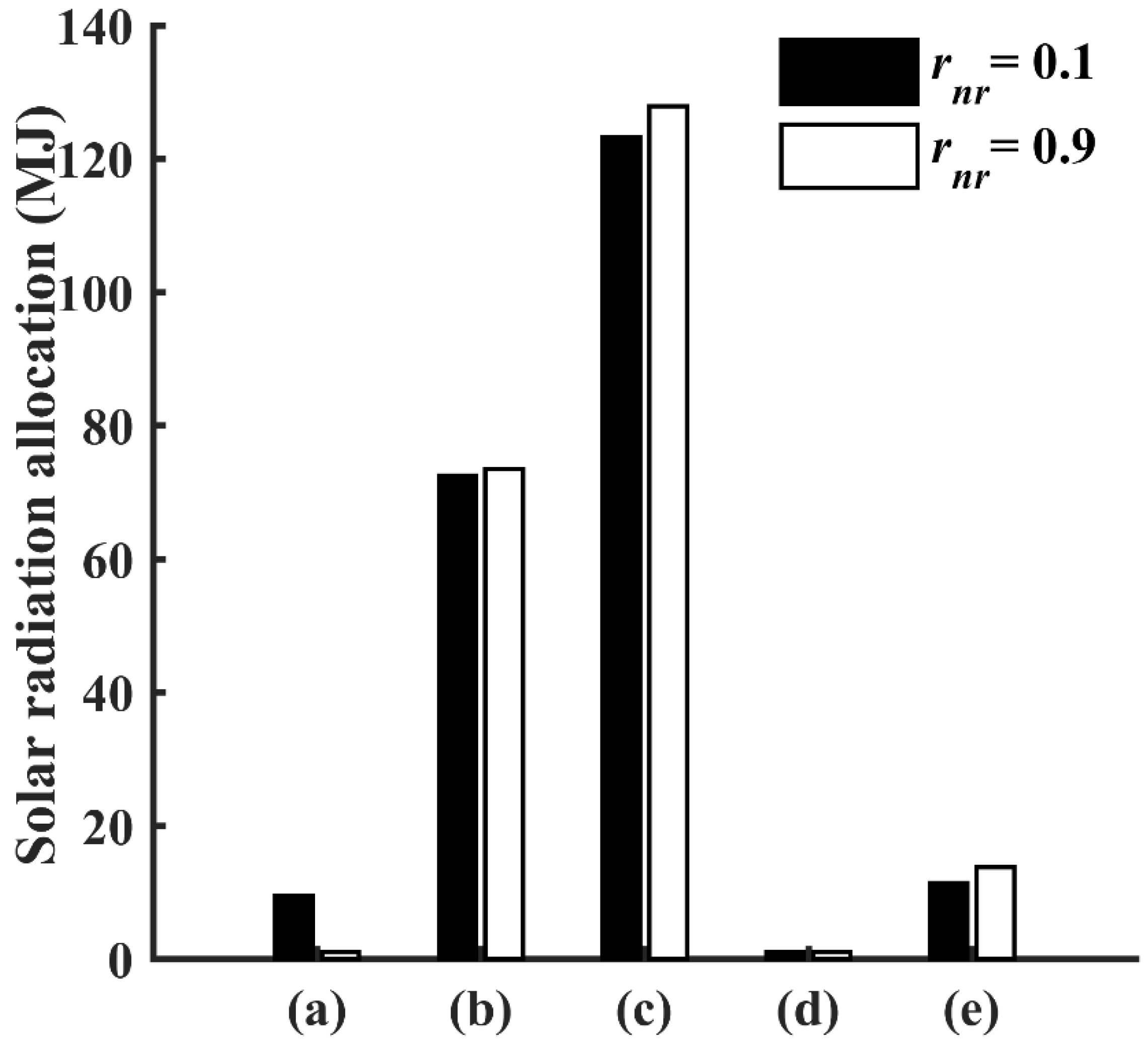
The results of the solar radiation energy allocation in the solar greenhouse are presented in Figure 9, allowing the comparison between the experimental greenhouse, which has a north roof with low inner surface reflectance (rnr = 0.1), and the optimized greenhouse, which has a north roof with high inner surface reflectance (rnr = 0.9). It can be observed that the two solar greenhouses do not exhibit significant differences in solar radiation allocation. For the solar greenhouse with the optimized north roof, during the lighting hours, the cumulative solar radiation (SRA) allocated to the inner surfaces of the north roof, north wall, ground, and the thermal blanket-covered section and the lighting section of the south roof are 1.06, 73.47, 127.92, 1.33, and 13.76 MJ, respectively; here, the solar radiation energy lost through the lighting section of the south roof increases by 20.0% owing to the enhanced interior reflection. Then, the total solar radiation availability of the optimized solar greenhouse obtained by Equation (34) has a value of 203.51 MJ/m, which is 1.3% lower than that of the experimental solar greenhouse with a north roof with low inner surface reflectance. Nevertheless, it must be noted that the solar radiation availability for the two regenerative components, i.e., the north wall and ground, are increased by 1.3 and 3.8%, respectively. This indicates that enhancing the interior reflection by increasing the inner surface reflectance of the north roof optimizes the interior solar energy allocation, and therefore has some positive effect on the development of the interior thermal environment.
Next, the spatial distributions of the solar radiation for the two solar greenhouses with different north roofs are compared. The spatial distributions of the average solar radiation intensity of the greenhouses with common and optimized north roofs are illustrated in Figure 6d and Figure 10, respectively. The average distributions of the solar radiation intensity on the four horizontal planes at the heights of 0, 1.0, 2.0, and 3.0 m, respectively, are highlighted in Figure 11.
From Figure 10, it is evident that the solar radiation intensity in the solar greenhouse with a north roof with high inner surface reflectance is generally larger than the experimental solar greenhouse, particularly in the innermost regions near the north wall. This induces a smaller solar radiation intensity amplitude from north to south in the optimized solar greenhouse, as clearly depicted in Figure 11. Considering the entire horizontal plane, the average difference in the solar radiation intensity between the two solar greenhouses is 11.85 W/m2 for the 0 m-height plane, 3.95 W/m2 for the 1.0 m-height plane, 4.54 W/m2 for the 2.0 m-height plane, and 5.54 W/m2 for the 3.0 m-height plane, which correspond to increases of 3.8, 1.3, 1.5, and 2.0%, respectively, for the light environment quality inside the solar greenhouse. When considering only the region within 3.0 m from the north wall, the average differences of the solar radiation intensity between the two solar greenhouses are 18.96 W/m2 for the 0 m-height plane, 6.78 W/m2 for the 1.0 m-height plane, 8.84 W/m2 for the 2.0 m height-plane, and 11.98 W/m2 for the 3.0 m-height plane, which correspond to increases of 6.8, 2.6, 3.5, and 5.0%, respectively, for the light environment quality in the north side of the solar greenhouse. Therefore, it can be determined that the north roof with high inner surface reflectance has a function of supplementary lighting, and its application can improve the light environment in the low light region near the north wall and relieves the light distribution gap between the south and north for a solar greenhouse, thereby providing better light conditions for crops.

4.2.3. Thermal Blanket-Covered Length on the South Roof during the Lighting Hours

In Chinese solar greenhouses design, the enhancement of the heat storage and release of the north wall has been considered the most feasible improvement in the thermal environment [48]. However, as reported in Section 4.2.2, the enhancements of the solar radiation availability for the north wall by increasing the inner surface reflectance of the north roof are limited. This is because the beam radiation contributes the most to the total solar radiation allocated to the north wall. In reality, the solar radiation availability of the heat-store/release component (the north wall) is mainly affected by the shadow areas projected by both the north roof and the thermal blanket-covered south roof. As previously mentioned, the north roof has a fixed length while the length of the thermal blanket on the south roof varies with time. According to the common solar greenhouse design standard, a horizontal length of the thermal blanket on the south roof should be set to 0.8 m during the lighting hours [38]; however, the thermal blanket length sometimes becomes larger and reaches even 1.5 m in current practical applications [49]. Based on the established solar greenhouse light environment model, the projection regions can be obtained.
Consider a rolled-up thermal blanket on the south roof following the solar greenhouse design standard. Figure 12 illustrates the length variation of the shadow projected on the north wall’s inner surface from 8 November (beginning of winter) to 20 March (vernal equinox), which is the typical cold time in Jiuquan when off-season vegetables are produced; the lengths projected by the north roof and the thermal blanket-covered south roof are also highlighted, respectively. The value of the shadow length on a day is selected as the average projection length between 11:00 to 15:00, because there is a one-hour time difference between the times in the experimental site (98°30′ E) and the Nation Time Service Center site (120° E). It can be observed that, during the simulation period, the projected shadow length is close to zero for just about two months around the winter solstice owing to the small solar altitude at this time of year in the northern hemisphere. Therefore, the entire inner surface of the north wall can accept the solar beam radiation in the two months’ time. However, after 20 January, the shadow length projected on the wall’s inner surface increases with time; especially in the the middle of February, the shadow area has already represented more than a fourth of the wall’s entire inner surface and continues to increase rapidly. Moreover, it can be observed that the shadow is mostly generated by the thermal blanket-covered south roof. It is important to note that, according to the past ten years’ data provided by the China Meteorological Administration data center, the outside minimum average temperature in January and February in the studied area is below −10 °C. Therefore, for a solar greenhouse, the heat storage/release capacity of the north wall, which depends on the solar radiation availability, will be critical in ensuring a safe nocturnal environment for crop growth owing to the intermittent nature of solar energy. However, such a wide range of shadows significantly reduces the potential amount of solar energy stored in the north wall, which will lead to inadequate energy supply for the solar greenhouse heating during the nighttime, thereby threatening the crop growth.
To solve this problem, the parking position of the thermal blanket during the lighting hours was optimized in this study because the thermal blanket is the main section generating the shadow on the north wall, and, therefore, it is not necessary to change the north roof structure adding manufacturing difficulties. For the optimization, the rolled-up blanket is installed at a high enough height, allowing the length of the thermal blanket-covered south roof to equal to zero, which allows more beam radiation to enter the greenhouse in lighting hours, increasing the heat storage of the north wall during the period lasting from 15 January to 20 March.
To demonstrate the effectiveness of the optimization measure, a simulation was carried out based on the already optimized solar greenhouse described in 
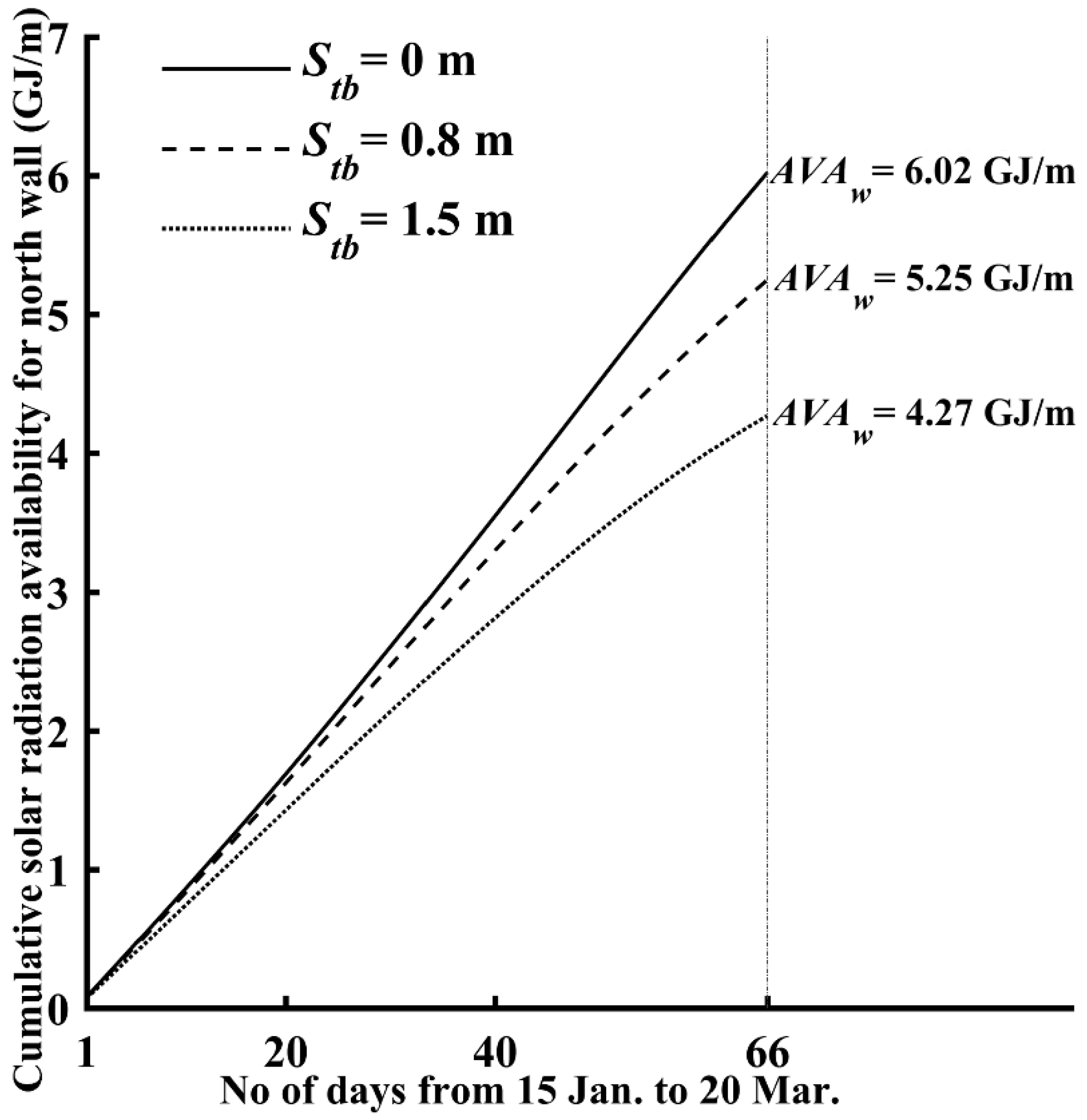
Section 4.2.2 with different thermal blanket parking positions, by using the established light environment model. The calculation time is between 15 January and 20 March, and clear sunny weather is assumed for all days. In Figure 13, the cumulative solar radiation availability for the north wall day by day in the solar greenhouse with the optimized thermal blanket parking position are shown and compared with the simulated results in the greenhouses with a 0.8 m and a 1.5 m thermal blanket-covered in the lighting hours. The comparison indicates that the application of the optimization measure significantly increases the solar radiation availability for the north wall. In the entire calculation period, when compared to the 0.8 m and 1.5 m thermal blankets for the lighting hours, the covered blanket length of zero increases the north wall’s solar radiation availability by 0.77 and 1.75 GJ/m, respectively, for a one-meter section along the east-west orientation, corresponding to an improvement of 14.7 and 41.1%, respectively. Accordingly, it is strongly recommended to park the rolled-up thermal blanket high enough on the roof during the lighting hours; this will maximize the north wall’s solar radiation availability and enhance its heat storage/release capacity.

5. Conclusions

Solar radiation is the sole energy source for Chinese solar greenhouse agriculture. The allocation of solar radiation in the solar greenhouse system directly affects the greenhouse thermal environment development, whereas the spatial distribution of solar radiation reflects the light conditions on which crop growth depends. Therefore, the light environment is a key indicator for evaluating a solar greenhouse’s performance. For this purpose, a solar greenhouse light environment model was established and validated in this study, considering greenhouse structures, materials, and interior solar radiation progresses. With the established model, the solar greenhouse light environment was dynamically simulated in terms of solar beam radiation, diffuse radiation, and multi-reflection, with target date/time, geographic location, weather conditions, solar greenhouse’s orientation and shape parameters, and optical properties of the building materials as the inputs, based on the law of the solar trajectory, the radiation angular distribution coefficient method, and the multiple diffuse reflection method. By using this model, the solar radiation allocation, the spatial distribution of the solar radiation, and the solar radiation availability in a solar greenhouse can be determined quantitatively. The following conclusions may be drawn:
(1)
The solar greenhouse light environment model established in this study is valid because the simulated and measured results are consistent for different weather conditions. The MPE was calculated to be 1.67% for clear sunny weather and 10.30% for cloudy weather, and a satisfactory determination coefficient R2 of 0.9756 between the simulated and measured results was obtained for the established model.
(2)
The varying slope angle along the curved south roof results in a nonuniform beam radiation intensity and beam transmittance on the south roof. This leads to a significantly complex light environment inside the solar greenhouse. Generally, the spatial distribution of solar radiation exhibits a decrease in both south-to-north and bottom-to-top directions within a solar greenhouse.
(3)
The seasonal spatial distribution of the solar radiation in a solar greenhouse is quantitatively investigated with the established model. The results suggest that the solar greenhouse can be used to plant crops that require an illuminance in the range of 42,000–57,200 lux in spring and summer and crops that require an illuminance in the range of 25,000–40,000 lux in autumn and winter.
(4)
Increasing the inner surface reflectance of the north wall by whitewashing enhanced the interior refection. The north roof with high inner surface reflectance is a supplementary lighting component, which helps effectively improve the light environment of the low light region, with average increases in the solar radiation intensity of 18.96 W/m2 (6.8%), 6.78 W/m2 (2.6%), 8.84 W/m2 (3.5%), and 11.98 W/m2 (5.0%) for the 0, 1.0, 2.0, and 3.0 m height-planes, respectively, in the region within 3.0 m from the north wall.
(5)
Between 15 January and 20 March, the thermal blanket covered-south roof with a length of zero in the lighting hours increases the cumulative solar radiation availability for the north wall by 0.77 and 1.75 GJ/m along a one-meter section along the east-west orientation; this is 14.7 and 41.1% higher than when the thermal blanket occupies a horizontal length of 0.8 and 1.5 m, respectively, on the south roof.
Although the validation and application of the established solar greenhouse light environment model were performed in the Jiuquan city of the Hexi Corridor, the model is applicable and convenient for Chinese solar greenhouses in different regions with different climates and geographical features. With the established model, the dynamic light environment in a solar greenhouse can be predicted quantitatively to optimize the greenhouse lighting regulation and planting pattern. Additionally, the model provides precise boundary conditions for the energy balance and thermal environment development of a solar greenhouse system. It is expected that the solar greenhouse light environment model established in this study will be used to create desirable growth environments for crops and enhance the production efficiency.

Author Contributions

Conceptualization: J.X. and J.Y.; Data curation: X.Z., J.L., J.Z., C.T., J.L., Z.H. and C.W.; Formal analysis: J.X. and J.Y.; Investigation: X.Z. and J.L.; Methodology: X.Z.; Software: X.Z.; Validation: X.Z., J.L., J.Z., C.T., J.L., Z.H. and C.W.; Writing—original draft: X.Z. All authors have read and agreed to the published version of the manuscript.

Funding

This research is financially supported by the State Special Fund for Agro-Scientific Research in the Public Interest (201203002) and the Special Fund for Science & Technology Innovation and Development Guided by Gansu Province (2018ZX-02).

Conflicts of Interest

The authors declare no conflict of interest.

Notation

A, B, Cend points of two circular arcs composing the south roof
AVAsolar radiation availability in a solar greenhouse (MJ/m)
CCcloud cover
ecalculating element in radiation angular distribution calculation
echaracteristic size of the calculating element (m)
Fradiation angular distribution coefficient
Hheight of the solar greenhouse’s ridge (m)
hsolar altitude angle (°)
I0solar radiation constant (W·m−2)
Ib, Id, Irbeam, diffuse, and ground-reflected solar radiation intensity reaching the south roof (W·m−2)
Ibh, Idhbeam and diffuse solar radiation intensity reaching an outside horizontal surface (W·m−2)
Iben, Iden, Ienbeam, diffuse/reflective, and total solar radiation intensity entering the solar greenhouse (W·m−2)
Ibin, Idin, Irin, Iinbeam, diffuse, reflective, and total solar radiation intensity at an interior point (W·m−2)
kslope of sunray
Llength of each component in the solar greenhouse cross-section (m)
LUXilluminance (lux)
llength of connection line between two calculating elements (m)
Ntotal number of solar radiation reflections occurring within the solar greenhouse
Ocircle center of circular arc
Patmosphere transparency coefficient
P , P perpendicular and parallel components of solar radiation
parbitrary point in the solar greenhouse cross-section
rsurface reflectivity
routreflectivity of the outside ground
Rradius of circular-arc (m)
REtotal reflective radiation reaching each inner surface in one reflection (W)
Shorizontal length of the south roof (m)
SRAcumulative solar radiation allocated to each internal surface in a day (MJ)
SREcumulative solar radiation entering a solar greenhouse through the south roof in a day (MJ)
SRRexternal cumulative solar radiation reaching the south roof in a day (MJ)
t1, t2starting and ending times of lighting hours (h)
(x, y)point coordinates
Zrefractive index
Greek letters
αslope angles at the ends of circular-arc (°)
βslope angle (°)
γsolar azimuth angle (°)
γGazimuth angle of the solar greenhouse (°)
δangle between a line connecting two elements and the normal to each element (°)
θincident angle of sunrays (°)
θZangle of refraction (°)
ρsurface solar radiation absorbance
τbbeam radiation transmittance
τddiffuse radiation transmittance
Subscripts and Superscripts
ccrop canopy
gground
inumber of solar radiation reflection
jnumber of each internal surface in the solar greenhouse
lrlighting roof
nrnorth roof
srsouth roof
tbthermal blanket-covered south roof
ttime
wnorth wall
cloudy weather

References

  1. Mussard, M. Solar energy under cold climatic conditions: A review. Renew. Sustain. Energy Rev. 2017, 74, 733–745. [Google Scholar] [CrossRef]
  2. Hassanien, R.H.E.; Li, M.; Wei, D.L. Advanced applications of solar energy in agricultural greenhouses. Renew. Sustain. Energy Rev. 2016, 54, 989–1001. [Google Scholar] [CrossRef]
  3. Shukla, A.; Sharma, A.; Kant, K. Solar Greenhouse With Thermal Energy Storage: A Review. Curr. Sustain. Renew. Energy Rep. 2016, 3, 58–66. [Google Scholar] [CrossRef]
  4. Berroug, F.; Lakhal, E.K.; El Omari, M.; Faraji, M.; El Qarnia, H. Thermal performance of a greenhouse with a phase change material north wall. Energy Build. 2011, 43, 3027–3035. [Google Scholar] [CrossRef]
  5. Ghasemi Mobtaker, H.; Ajabshirchi, Y.; Ranjbar, S.F.; Matloobi, M. Solar energy conservation in greenhouse: Thermal analysis and experimental validation. Renew. Energy 2016, 96, 509–519. [Google Scholar] [CrossRef]
  6. Bot, G.P.A.; Braak, N.J.V.D.; Challa, H.; Hemming, S.; Rieswijk, T.; Straten, G.V.; Verlodt, I. The Solar Greenhouse: State of the art in energy saving and sustainable energy supply. Acta Hortic. 2005, 691, 501–508. [Google Scholar] [CrossRef] [Green Version]
  7. Panwar, N.L.; Kaushik, S.C.; Kothari, S. Solar greenhouse an option for renewable and sustainable farming. Renew. Sustain. Energy Rev. 2011, 15, 3934–3945. [Google Scholar] [CrossRef]
  8. Xie, J.M.; Yu, J.H.; Chen, B.H.; Feng, Z.; Li, J.; Zhao, C.; Lyu, J.; Hu, L.L.; Gan, Y.T.; Siddique, K.H.M. Chapter One—Facility Cultivation Systems “设施农业”: A Chinese Model for the Planet. Adv. Agron. 2017, 145, 1–42. [Google Scholar]
  9. Sethi, V.P.; Sumathy, K.; Lee, C.; Pal, D.S. Thermal modeling aspects of solar greenhouse microclimate control: A review on heating technologies. Sol. Energy 2013, 96, 56–82. [Google Scholar] [CrossRef]
  10. Hassanain, A.A.; Hokam, E.M.; Mallick, T.K. Effect of solar storage wall on the passive solar heating constructions. Energy Build. 2011, 43, 737–747. [Google Scholar] [CrossRef]
  11. Sethi, V.P. On the selection of shape and orientation of a greenhouse: Thermal modeling and experimental validation. Sol. Energy 2009, 83, 21–38. [Google Scholar] [CrossRef]
  12. Imam, S.; Fitzgerald, C.M.; Cook, E.M.; Donohue, T.J.; Noguera, D.R. Quantifying the effects of light intensity on bioproduction and maintenance energy during photosynthetic growth of Rhodobacter sphaeroides. Photosynth. Res. 2015, 123, 167–182. [Google Scholar] [CrossRef] [PubMed]
  13. Nawalany, G.; Bieda, W.; Radoń, J.; Herbut, P. Experimental study on development of thermal conditions in ground beneath a greenhouse. Energy Build. 2014, 69, 103–111. [Google Scholar] [CrossRef]
  14. Zhang, X.D.; Lv, J.; Dawuda, M.M.; Xie, J.M.; Yu, J.H.; Gan, Y.T.; Zhang, J.; Tang, Z.Q.; Li, J. Innovative passive heat-storage walls improve thermal performance and energy efficiency in Chinese solar greenhouses for non-arable lands. Sol. Energy 2019, 190, 561–575. [Google Scholar] [CrossRef]
  15. Esen, M.; Yuksel, T. Experimental evaluation of using various renewable energy sources for heating a greenhouse. Energy Build. 2013, 65, 340–351. [Google Scholar] [CrossRef]
  16. Çakır, U.; Şahin, E. Using solar greenhouses in cold climates and evaluating optimum type according to sizing, position and location: A case study. Comput. Electron. Agric. 2015, 117, 245–257. [Google Scholar] [CrossRef]
  17. Gupta, R.; Tiwari, G.N.; Kumar, A.; Gupta, Y. Calculation of total solar fraction for different orientation of greenhouse using 3D-shadow analysis in Auto-CAD. Energy Build. 2012, 47, 27–34. [Google Scholar] [CrossRef]
  18. El-Maghlany, W.M.; Teamah, M.A.; Tanaka, H. Optimum design and orientation of the greenhouses for maximum capture of solar energy in North Tropical Region. Energy Convers. Manag. 2015, 105, 1096–1104. [Google Scholar] [CrossRef]
  19. Mobtaker, H.G.; Ajabshirchi, Y.; Ranjbar, S.F.; Matloobi, M. Simulation of thermal performance of solar greenhouse in north-west of Iran: An experimental validation. Renew. Energy 2019, 135, 88–97. [Google Scholar] [CrossRef]
  20. Abdel-Ghany, A.; Picuno, P.; Al-Helal, I.; Alsadon, A.; Derahim, A.; Shady, M. Radiometric Characterization, Solar and Thermal Radiation in a Greenhouse as Affected by Shading Configuration in an Arid Climate. Energies 2015, 8, 13928–13937. [Google Scholar] [CrossRef] [Green Version]
  21. Wang, Q.; Zhang, H.T.; Liu, X.; Sun, Z.Q. Analysis on Temperature and Light in Sinking Solar Greenhouse. Chin. J. Agrometeorol. 2013, 34, 37–42. [Google Scholar]
  22. Zhang, Y.H.; Bai, Q.; Feng, M.I.; Sun, L.X. Determination and analysis on solar radiation of trapezoidal soil wall and soil surface in solar greenhouse. Trans. Chin. Soc. Agric. Eng. 2013, 29, 164–172. [Google Scholar]
  23. Tong, G.H.; Christopher, D.M.; Li, T.L.; Wang, T.L. Passive solar energy utilization: A review of cross-section building parameter selection for Chinese solar greenhouses. Renew. Sustain. Energy Rev. 2013, 26, 540–548. [Google Scholar] [CrossRef]
  24. Xuan, W.Y. Mathematical Model Establishment and Analysis for Greenhouse Surface Curve. J. Tianjin Agric. Sci. 2006, 12, 44–46. [Google Scholar]
  25. Chen, C.; Li, Y.; Li, N.; Wei, S.; Yang, F.G.; Ling, H.S.; Yu, N.; Han, F.T. A computational model to determine the optimal orientation for solar greenhouses located at different latitudes in China. Sol. Energy 2018, 165, 19–26. [Google Scholar] [CrossRef]
  26. Han, Y.D.; Xue, X.E.; Luo, X.L.; Guo, L.; Li, T.L. Establishment of estimation model of solar radiation within solar greenhouse. Trans. Chin. Soc. Agric. Eng. 2014, 30, 174–181. [Google Scholar]
  27. Ma, C.W.; Zhao, S.M.; Cheng, J.Y.; Wang, N.; Jiang, Y.C.; Wang, S.Y.; Li, B.M. On establishing light environment model in Chinese solar greenhouse. J. Shenyang Agric. Univ. 2013, 44, 513–517. [Google Scholar]
  28. Yang, W.X.; Ma, C.W. Simulation Effect of Inclination Angle of Roof on the Light Environment of Sunlight Greenhouse. Nor. Horticul. 2019, 43, 78–82. [Google Scholar]
  29. Xu, H.J.; Cao, Y.F.; Li, Y.R.; Gao, J.; Jiang, W.J.; Zou, Z.R. Establishment and application of solar radiation model in solar greenhouse. Trans. Chin. Soc. Agric. Eng. 2019, 35, 160–169. [Google Scholar]
  30. Zhang, S.F.; Bai, W.B.; Pan, T.R.; Wu, Z.M.; Wang, Y.S. study on the optimized parameters of lighting curve of front roof of solar greenhouse in the north of china. J. Shanxi Agric. Univ. 2013, 33, 336–341. [Google Scholar]
  31. Duffie, J.A.; Beckman, W.A. Solar Engineering of Thermal Processes, 4th ed.; John Wiley & Sons, Inc.: Hoboken, NJ, USA, 2013. [Google Scholar]
  32. Petržala, J.; Kómar, L.; Kocifaj, M. An advanced clear-sky model for more accurate irradiance and illuminance predictions for arbitrarily oriented inclined surfaces. Renew. Energy 2017, 106, 212–221. [Google Scholar] [CrossRef]
  33. Yan, Q.S.; Zhao, Q.Z. Building Thermal Process; Architecture & Building Press: Beijing, China, 1986. [Google Scholar]
  34. Ahamed, M.S.; Guo, H.; Tanino, K. Energy-efficient design of greenhouse for Canadian Prairies using a heating simulation model. Int. J. Energ. Res. 2018, 42, 2263–2272. [Google Scholar] [CrossRef]
  35. Schubert, E. Refractive Index and Extinction Coefficient of Materials. 2004. Available online: http://www.rpi.edu/%7eschubert/ (accessed on 11 September 2017).
  36. Cossu, M.; Murgia, L.; Ledda, L.; Deligios, P.A.; Sirigu, A.; Chessa, F.; Pazzona, A. Solar radiation distribution inside a greenhouse with south-oriented photovoltaic roofs and effects on crop productivity. Appl. Energy 2014, 133, 89–100. [Google Scholar] [CrossRef]
  37. Xie, J.M.; Yu, J.H.; Chen, B.H.; Feng, Z.; Lyu, J.; Hu, L.L.; Gan, Y.T.; Siddique, K.H.M. Gobi agriculture: An innovative farming system that increases energy and water use efficiencies. A review. Agron. Sustain. Dev. 2018, 38, 62. [Google Scholar] [CrossRef] [Green Version]
  38. Cao, Y.; Jing, H.; Zhao, S.; Zou, Z.; Bao, E. Optimization of back roof projection width and northern wall height in Chinese solar greenhouse. Trans. Chin. Soc. Agric. Eng. 2017, 33, 183–189. [Google Scholar]
  39. Incropera, F.P.; Lavine, A.S.; Bergman, T.L.; DeWitt, D.P. Fundamentals of Heat and Mass Transfer, 6th ed.; John Wiley & Sons, Inc.: Hoboken, NJ, USA, 2007. [Google Scholar]
  40. Ju, X.L. Releations between irradiance and illuminance under cloudless sky. Acta Energy. Sin. 1999, 20, 190–195. [Google Scholar]
  41. Peri, G.; Rizzo, G.; Scaccianoce, G.; La Gennusa, M.; Jones, P. Vegetation and soil–related parameters for computing solar radiation exchanges within green roofs: Are the available values adequate for an easy modeling of their thermal behavior? Energy Build. 2016, 129, 535–548. [Google Scholar] [CrossRef]
  42. Kim, I.; Lee, S.C.; Kim, E.H.; Song, K.; Yang, T.J.; Kim, H.U. Genome-Wide Identification and Expression Analyses of the Fibrillin Family Genes Suggest Their Involvement in Photoprotection in Cucumber. Plants 2018, 7, 50. [Google Scholar] [CrossRef] [Green Version]
  43. Anguelova, T.; Warthesen, J. Lycopene stability in tomato powders. J. Food Sci. 2000, 65, 67–70. [Google Scholar] [CrossRef]
  44. Buttrose, M.S.; Sedgley, M. Some effects of light intensity, daylength and temperature on growth of fruiting and non-fruiting watermelon (Citrullus lanatus). Ann. Bot London 1978, 42, 599–608. [Google Scholar] [CrossRef]
  45. Lee, S.G.; Kim, S.K.; Lee, H.J.; Lee, H.S.; Lee, J.H. Impact of moderate and extreme climate change scenarios on growth, morphological features, photosynthesis, and fruit production of hot pepper. Ecol. Evol. 2018, 8, 197–206. [Google Scholar] [CrossRef] [Green Version]
  46. Xu, K.Z.; Shi, Y.L.; Xu, G.M.; Zhang, Z.A.; Cui, Q.H. Studies on Photosynthetic Temperature Characteristic of Cucumber Leaves in Protective Field. Acta Hortic. Sin. 1993, 1, 51–55. [Google Scholar]
  47. Li, H.Y.; Li, C.X.; Zhang, F.J.; Qi, H. The effect of different photoperiod on growth of summer squash seedling. Nor. Horticul. 2009, 5, 17–19. [Google Scholar]
  48. Sethi, V.P.; Sharma, S.K. Survey and evaluation of heating technologies for worldwide agricultural greenhouse applications. Sol. Energy 2008, 82, 832–859. [Google Scholar] [CrossRef]
  49. Tong, G.H.; David, M.C.; Li, T.L.; Bai, Y.K. Influence of thermal blanket position on solar greenhouse temperature distributions. Trans. Chin. Soc. Agric. Eng. 2010, 26, 253–258. [Google Scholar]
Figure 1. Pictures of a conventional greenhouse and a Chinese solar greenhouse.
Energies 13 01108 g001
Figure 2. Cross-section of a Chinese solar greenhouse: A, B, C, end points of two circular arcs composing the south roof; α1, α2, α3, slope angles at the ends of each circular-arc; R1, R2, radii of arcs AB and BC ; O1, O2, circle centers of arcs AB and BC H, the height of greenhouse ridge; S, the horizontal length of south roof.
Energies 13 01108 g002
Figure 3. Variations of slope angle β and beam radiation transmittance along the south roof.
Energies 13 01108 g003
Figure 4. Internal and external views of the experimental Chinese solar greenhouse.
Energies 13 01108 g004
Figure 5. Simulation and measurement results of the solar radiation intensity in the experimental greenhouse during the lighting hours of a typical sunny day (26 October) and of three cloudy days with different cloud cover (CC = 1 in 27 October, CC = 7 in 17 November, CC = 2 in 18 November).
Energies 13 01108 g005
Figure 6. Seasonal spatial distribution of the average solar radiation intensity during the lighting hours for the experimental solar greenhouse: (a) in the vernal equinox (20 March); (b) in summer solstice (21 June); (c) in autumn equinox (23 September); (d) in the winter solstice (22 December).
Energies 13 01108 g006
Figure 7. Solar radiation allocation in the experimental solar greenhouse in a sunny winter solstice day with the interior multi-reflection neglected and considered.
Energies 13 01108 g007
Figure 8. Distribution of the average solar radiation intensity along horizontal planes with different heights during the lighting hours of a sunny winter solstice day in the experimental solar greenhouse with and without interior solar radiation multi-reflection.
Energies 13 01108 g008
Figure 9. Solar radiation allocation in a sunny winter solstice day for two solar greenhouses with north roofs with different inner surface reflectance: (a) north roof; (b) north wall; (c) ground; (d) thermal blanket covered-south roof; (e) lighting south roof.
Energies 13 01108 g009
Figure 10. Spatial distribution of the average solar radiation intensity during the lighting hours of a sunny winter solstice day for a solar greenhouse having a north roof with high inner surface reflectance (rnr = 0.9).
Energies 13 01108 g010
Figure 11. Distribution of the average solar radiation intensity along horizontal planes with different heights during the lighting hours of a sunny winter solstice day for two solar greenhouses with north roofs with different inner surface reflectance.
Energies 13 01108 g011
Figure 12. Length of shadow projected on north wall’s inner surface from 8 November to 20 March: (a) winter begins, 8 November; (b) light snow, 22 November; (c) heavy snow, 7 December; (d) winter solstice, 22 December; (e) slight cold, 6 January; (f) great cold, 20 January; (g) spring begins, 4 February; (h) the rains, 19 February; (i) insects awaken, 5 March; (j) vernal equinox, 20 March.
Energies 13 01108 g012
Figure 13. Cumulative solar radiation availability for north wall day by day from 15 January to 20 March for two solar greenhouses with different thermal blanket parking positions during the lighting hours.
Energies 13 01108 g013
Table 1. Input parameters used for model validation.
ParameterValueParameterValueParameterValue
S (m)8.7βnr (°)42γG (°)0
H (m)4.9ρw0.9rw0.1
Lw (m)3.33ρnr0.9rnr0.1
α1 (°)10ρg0.9rg0.1
α2 (°)19ρc0.9rc0.1
α3 (°)79τb0.355–0.915rb0.085–0.645
βw (°)82τd0.84rd0.16

