Article

Fabrication of Skutterudite-Based Tubular Thermoelectric Generator

1
Department of Materials Science and Engineering, Korea Advanced Institute of Science and Technology (KAIST), Daejeon 34141, Korea
2
Flexible Thermoelectric Device Center (FTEDC), Korea Advanced Institute of Science and Technology (KAIST), Daejeon 34141, Korea
3
Department of Materials Science and Engineering, Hanbat National University, Daejeon 34158, Korea
4
Korea Institute of Energy Research, Daejeon 34129, Korea
*
Author to whom correspondence should be addressed.
These authors contributed equally to this work.
Energies 2020, 13(5), 1106; https://doi.org/10.3390/en13051106
Submission received: 13 January 2020 / Revised: 14 February 2020 / Accepted: 25 February 2020 / Published: 2 March 2020
(This article belongs to the Section D1: Advanced Energy Materials)

Abstract

:
The conversion efficiency of the thermoelectric generator (TEG) is adversely affected by the quality of thermal contact between the module and the heat source. TEGs with the planar substrate are not suitable for the curved heat sources. Several attempts have been made to tackle this issue by fabricating complex tubular-shaped TEGs; however, all efforts have been limited to low-temperature applications. Furthermore, the electrical contact resistance of the module is critical to achieving a high-power output. In this work, we developed the tubular TEG with significantly low specific contact resistance by optimizing the joining process. We show that the modified resistance welding (MRW) performed by spark plasma sintering (SPS) is an efficient joining method for the fabrication of the TE module, with high feasibility and scalability. This research seeks to suggest important design rules to consider when fabricating TEGs.

1. Introduction

Current cooperation between researchers and industries aims to develop new technologies for alternative renewable energy as a means to mitigate the increasing demand for electricity and curb over-reliance on the limited amount of fossil fuels [1]. One promising device for consideration is the thermoelectric generator (TEG). TEG is a solid-state device, consisting of a number of pairs of p-type and n-type semiconductors, that can directly convert heat to useful electric energy without any moving parts. The advantages of using TEG are that it is compact, reliable, and produces less noise [1,2,3,4]. One major application of TEG is the recovery of waste heat from different sources, from home appliances to industrial incinerators. Introducing TEGs to waste heat recovery has enabled simple and direct electrical power generation, widening the application even for sensing devices [5,6], solar cells [7,8], fuel cells [9,10], and automotive exhaust lines [11,12].
Unfortunately, the commercialization of the TEG module has been hindered by the low energy conversion efficiency of the thermoelectric material [2]. Thermoelectric conversion efficiency is proportional to the dimensionless thermoelectric figure of merit: z T = S 2 σ T κ , where S , σ , T , and κ are the Seebeck coefficient, electrical conductivity, absolute temperature, and thermal conductivity, respectively [1]. Several studies have been conducted to develop materials with high zT value, thereby increasing the efficiency of the thermoelectric device [13,14]. The conventional process for fabricating the TE module is limited to assembling cubical thermoelectric legs on a planar ceramic substrate [15,16,17], while most of the heat sources have an arbitrarily curved shape. The mismatch of the surface morphology causes high thermal contact resistance at the interface, eventually degrading the performance of the whole module, regardless of the material used [11]. Conductive polymer-based organic–inorganic hybrid [18] or screen printed flexible TEGs [19] were introduced to resolve the contact issue between the heat source and the TEG. Nevertheless, there are challenges for commercialization as they show far lower thermoelectric efficiency due to the low zT value of the organic-containing thermoelectric materials [18,19,20,21].
Ring-type TEGs, or tubular TEGs, have been designed as alternatives to deal with the aforementioned challenges and to achieve high efficiency via conformal contact to the heat source [22,23]. Nonetheless, most of the studies in terms of tubular TEG limit their material to the bismuth telluride ( B i 2 T e 3 ), which is for low-temperature power generation [23,24,25]. Applications of TEG at mid-temperature power generation are necessary considering the existence of mid-temperature waste heat sources such as incinerators, industrial furnaces, or automobile exhaust systems. For example, a catalytic converter equipped in an automobile requires over 200 °C to successfully react with exhaust gas, meaning that the temperature of the exhaust line would be greater than 200 °C [26]. Therefore, the necessity of tubular TEG to feature both stability and high performance concurrently at the mid-temperature range is important.
In this report, a skutterudite (SKD)-based tubular thermoelectric module was prepared by separately sintering p-type and n-type legs to optimize the thermoelectric efficiency. We selected skutterudite as a favorable thermoelectric material (CoSb3 for p-type, and CoSb2.85Te0.15 for n-type) for the fabrication of the module due to its wide operating temperature and commercial availability. Aside from the scalability, modified resistance welding (MRW) provides avenues to enhance thermoelectric properties when compared to previous reports that have no sintering [23] or co-sintering [27,28] process. We recorded a specific contact resistance below 7 × 10⁻⁶ Ω·cm2 for our module, using the MRW leading to an output power density of 0.52 W/cm2 at the temperature difference of 425 K.

2. Materials and Methods

2.1. Measurements of Thermoelectric Properties

Considering availability on a commercial scale with moderate TE properties, skutterudite (CoSb3) was chosen as a TE leg. Commercially available p-type undoped CoSb3 and Te-doped n-type CoSb2.85Te0.15 pellets were purchased (Toshima Co., Ltd., Tokyo, Japan). Seebeck coefficient and electrical conductivity of the pellets were simultaneously measured using a commercial apparatus (BS-1, Bluesys Co., Ltd., Daejeon, Korea). Thermal diffusivity was measured using the laser flash method (LFA457, NETZSCH, Selb, Germany). Thermal conductivity was estimated by calculating the product of thermal diffusivity (d), heat capacity ( C p ) , and density ρ . The theoretical heat capacity of CoSb3 was used, and density was calculated geometrically.

2.2. Machining of the Components

The pellets were machined into a 5 mm-thick cylindrical shape with an outer diameter of 30 mm and an inner diameter of 20 mm by wire electrical discharge machining. OFHC (Oxygen-free high conductivity) copper was used for the electrode material due to its high electrical conductivity. We found that the maximum power output or conversion efficiency is different by electrode thickness. Moreover, we also considered a processability in forming a good contact between electrodes and TE material. Therefore, a final thickness of 1 mm was determined by considering overall conditions. Hot side and cold side electrodes with a thickness of 1 mm and a width of 5 mm were positioned at the inner and outer peripheral of the cylindrical pellet, respectively. Silver-containing brazing sheets were inserted at both sides of the electrode to mechanically join it with the SKD. Ceramic fibers were used as insulation to shield exposed contact areas.

2.3. Joining

The Joining of the copper electrodes to the SKDs was done by modified resistance welding (MRW). The assembled module was placed on the graphite mold with a diameter of 30 mm, and each side of the module was compressed by a graphite punch with a diameter of 20 mm at the high temperature and pressurized by spark plasma sintering (SPS).

2.4. Analysis on the Joining Interface

The joining interface between the electrode and the SKD was analyzed by a field-emission scanning electron microscope (SU5000, Hitachi, Tokyo, Japan) equipped with an energy-dispersive X-ray spectroscopy (EDS) detector. Electrical resistance was measured while moving a microprobe at the joining surface. The specific contact resistance of the interface was calculated by multiplying the electrical resistance at the interface with the contact area.

2.5. Module Performance Evaluation

The tubular module is placed on semi-cylindrical graphite support with a curved heating cartridge. The bottom side of the graphite support is cooled with water. In order to ensure efficient heat transfer, 0.5 kg of brass with a 1 kg balance was applied onto the module to improve the contact between the heat source and the module. The temperature of the hot side and the cold side of the module was measured by a K-type thermocouple, and the open-circuit voltage was measured by an electric multimeter. The average area between the hot side and cold side was used for the power density calculation.

3. Results and Discussion

3.1. Thermoelectric Properties of the Materials

Thermoelectric property including the Seebeck coefficient, electrical conductivity, thermal conductivity, and dimensionless figure of merit (zT) of the thermoelectric materials as a function of temperature is shown in Figure 1. Although it is widely reported that skutterudite has high-performance zTmax of over one [14,29,30], commercialized Te-doped SKD shows limited performance. To check the feasibility and the applicability of fabricating tubular thermoelectric generators on a commercial scale, we used commercially available p-type CoSb3 and n-type CoSb2.85Te0.15 as thermoelectric materials for MRW modules.
The p-type SKD showed almost 10% of zTmax as compared to the n-type SKD. This zT value is consistent with the previous work by Liu et al. [31]. Due to the low zT of p-type segment, one pair of SKD only shows maximum zTave below 0.25 when the module is subjected to the temperature between 623 K (hot side) and 298 K (cold side). Since the overall performance of the material, especially in the p-type, is not so high, we designed a viable and efficient process to fabricate the tubular thermoelectric generator.

3.2. Fabrication of the Tubular Module

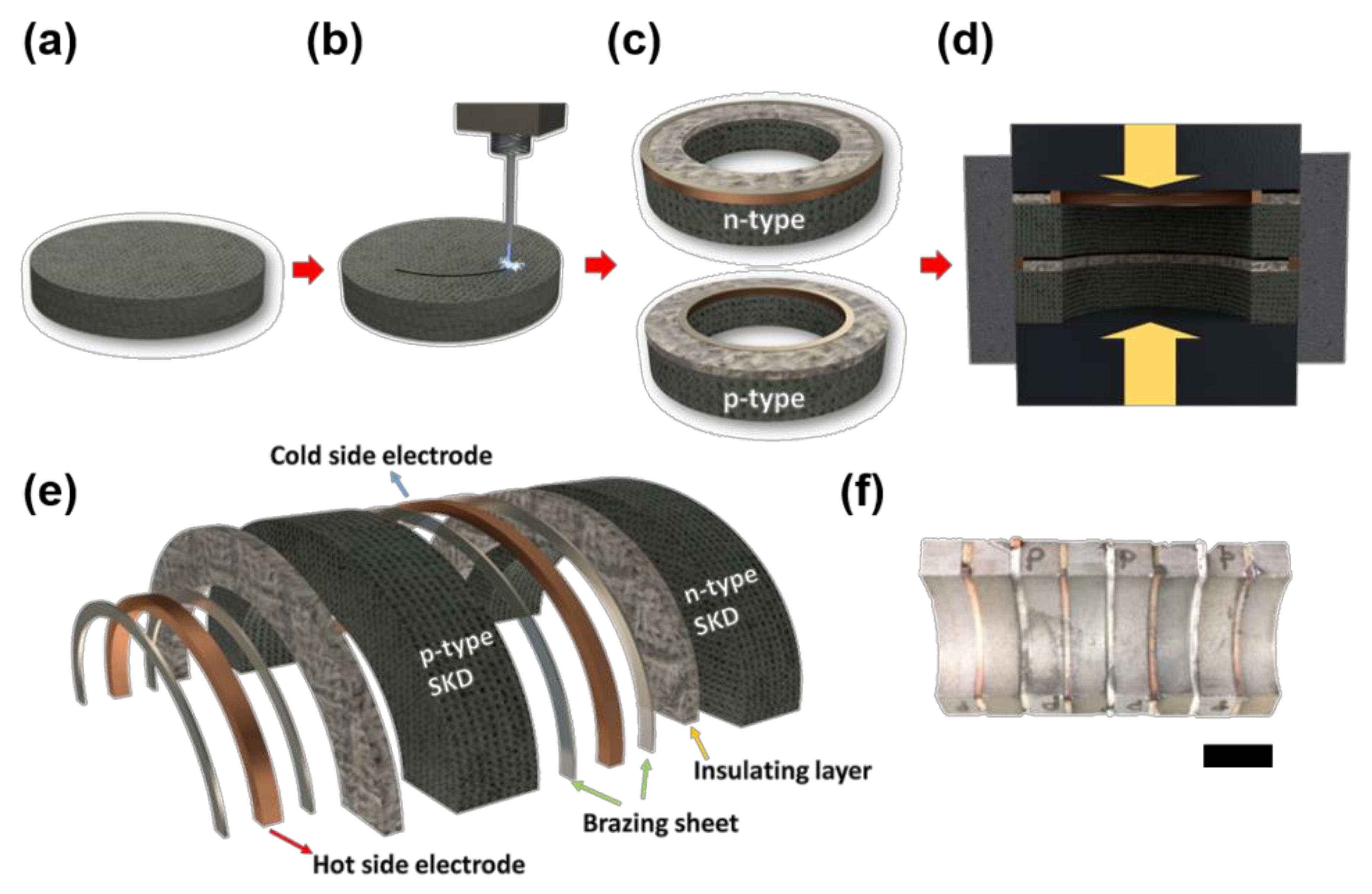
The fabrication process of the tubular thermoelectric generator is schematically shown in Figure 2. The process starts with slicing the sintered pellet into an appropriate thickness, which determines the heat-absorbing area of each TE element. The center of the pellet is cut out by wire electric discharge machining (WEDM). After that, cold side electrodes are positioned at the periphery of the outer radius of SKD. Brazing sheets are placed on top of the electrode and the rest of the area is covered by an insulating layer. The process is similar in the case of the hot side electrode, except for the electrode diameter. The hierarchical structure of the assembly is described in detail in Figure 2e. The hot side electrode, with direct contact to the heat source, has a smaller diameter than a cold side electrode. Two brazing sheets are placed at both sides of the electrode to mechanically join two different types of TE material to the electrode. Insulating layers are inserted between each TE material to electrically separate them. The mechanical and electrical joining of the electrode is done by modified resistance welding (MRW) using spark plasma sintering (SPS) equipment, as shown in Figure 2d. The digital photograph of the fabricated tubular thermoelectric generator with four pairs of SKD is shown in Figure 2f.
The joining process by the MRW method takes place in a sequence of steps. First, a high current is directed from the graphite punch to the assembly as a result of a high voltage during SPS. The brazing sheet, which has a low melting point compared to the other components, melts and forms an interface between the electrodes due to the high electrical resistance as a result of Joule heating. Unlike conventional co-sintering, which sinters TE and metal powders together, the MRW method joins already sintered pellets with the electrode. Co-sintering can be detrimental to the thermoelectric properties, since the optimum sintering temperature and pressure vary for n- and p-type TE materials due to the difference in composition.
For example, Chiu et al. reported that only a temperature difference of 50 K from the optimum sintering condition can result in a drop of the overall thermoelectric properties, especially zT by 75% of the optimum value [32]. Generally, in the case of skutterudite, the difference of the sintering temperature between the p-type and the n-type is about 100 K [14], which can significantly affect the property. Therefore, from the viewpoint of not only a facile fabrication but also high performance, it is beneficial to introduce MRW for the fabrication of modules.

3.3. Characterization of the Joining Interface

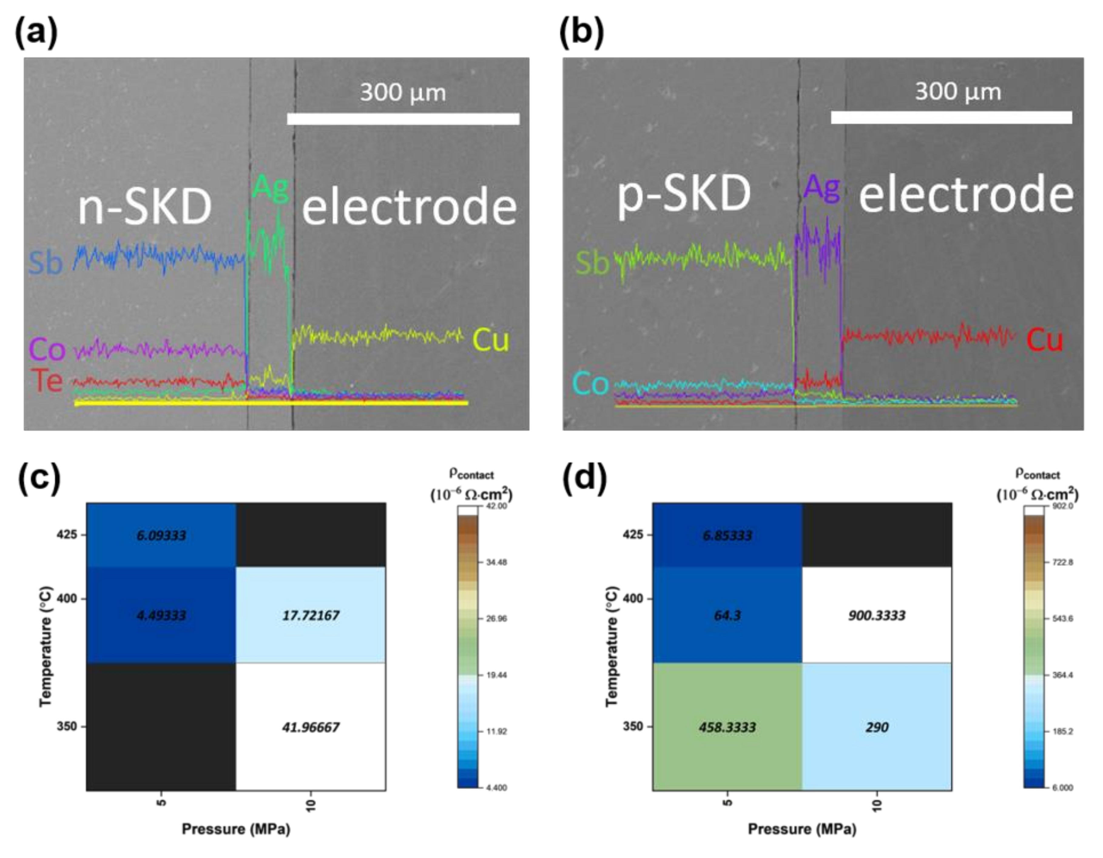
A low-magnification SEM image with an EDS line scan profile of the bonded interface between the TE material and the electrode is shown in Figure 3a,b. From the SEM, the interface is perfectly joined and devoid of cracks with no interdiffusion between the components. To find out the optimum joining condition, we measured the specific contact resistance at different temperatures and pressures (Figure S1). A summary of the specific contact resistance (ρcontact) for various joining conditions is shown for n-type in Figure 3c and p-type in Figure 3d. Generally, specific contact resistance decreases as temperature rises, but this is not the case for the pressure. No bonding is formed at 425 °C, 10 MPa condition in both n- and p-type SKD, including 350 °C, 5 MPa for n-type SKD. The optimum sintering conditions were observed at a temperature of 425 °C, and a pressure of 5 MPa, resulting in an n-type specific contact resistance of 6.093 μΩ·cm2 and p-type specific contact resistance of 6.853 μΩ·cm2. This specific contact resistance is only 1/100 of the previously reported value between the SKD–Cu interface [33], but also comparable to the value between the SKD–MoCu interface [34]. More detailed comparison is given in supplementary material (Table S1).
In essence, the low specific contact resistance is practically important for module fabrication to reduce total module resistance, since the theoretical maximum power output of the module is given by the following Equation (1) [35]:
P m a x = N V O C 2 4 R
where N is a number of pairs, VOC is an open circuit voltage, and R is a total resistance of the module. In this formula, R consists of three components: internal resistance, wire resistance, and contact resistance. Internal resistance arises from the electrical resistivity of the thermoelectric material, the electrode, and the brazing material. Wire resistance comes from the electrical resistivity of the wire connection at each end of the electrode. Finally, contact resistance exists between the interfaces of the components such as TE material–electrode, wire–electrode, etc. If materials used to fabricate the module are highly conductive, and the length of the wire is not too long, the effect of the contact resistance would be comparable with the other two components.

3.4. Measurement and Estimation of the Output Characteristic

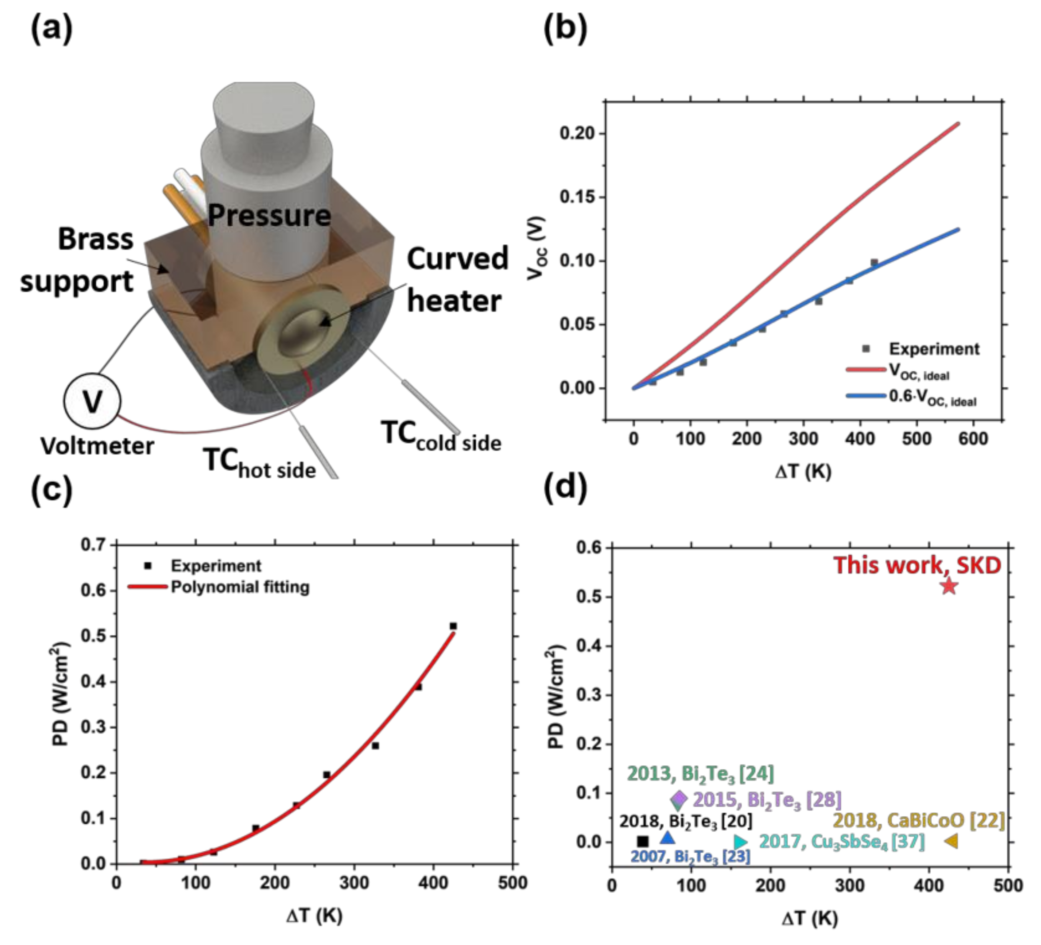
To test the power generation performance of the fabricated module, we designed the measurement setup as shown in Figure 4a. The TEG module was placed on a graphite mold with a circular heat source attached. The most challenging part of the measurement was to determine the hot and cold side temperature of the module due to its curved surface. In order to minimize the effect of this problem, specially designed thin thermocouples with a diameter under 0.1 mm were used. To ensure sufficient thermal contact between the TEG and the heat source, a load was placed and balanced with a brass support. The measured VOC of one paired tubular module by temperature difference is shown in Figure 4b. Ideally, the VOC of p–n junction pairing in the thermoelectric module at a given temperature can be evaluated with Equation (2) [36].
V O C ,   i d e a l = T c T h ( S p T S n T ) d T
Here, Tc and Th, Sp(T), and Sn(T) is the cold side temperature, hot side temperature, Seebeck coefficient of p-type, and Seebeck coefficient of n-type TE material, respectively. However, due to several reasons such as non-uniform temperature distribution, or heat transfer by convection, there is a decrease in effective temperature difference over the device. Therefore, our module recorded about 60% of the theoretical VOC output.
The maximum power output of the module was estimated by the temperature-dependent electrical conductivity and VOC value for Equation (1). The detailed calculation of the electrical resistance is given in the supporting information. In addition, power density (PD) measures the power generated in a given area and is calculated by the ratio of maximum power output to the heat-absorbing area. Obviously, the power density is independent of the number of pairs in series and so higher power output can be obtained. Thus, it is crucial to improve the power density of the module.
The calculated power density of the tubular module with a polynomial fitting (of order 2) is shown in Figure 4c. Our SKD module exhibited a superior power density of 0.52 W/cm2 at a temperature difference of 425 K compared to an organic-based thermoelectric module which has low operating temperature and power output [21]. A comparison with inorganic tubular thermoelectric modules is shown in Figure 4d. Much work has been devoted to developing the Bi2Te3-based module [20,23,24,28], which is capable of generating power efficiently at room temperature. Although there are several works that fabricated tubular modules with higher operating temperatures, power density is not so high [22,37]. Our SKD module takes advantage of both the temperature range and power output while preserving the curved morphology of the whole device.
The structural advantage of the output power of the TEG has been estimated by Kim et al. [20]. The difference in output voltage per thermocouple increases as the temperature difference between the hot side and the cold side increases. For the application of waste heat recovery in the mid-temperature region, the temperature difference would be much larger than that of a low-temperature application. Therefore, the benefit from the tubular morphology becomes much more significant.
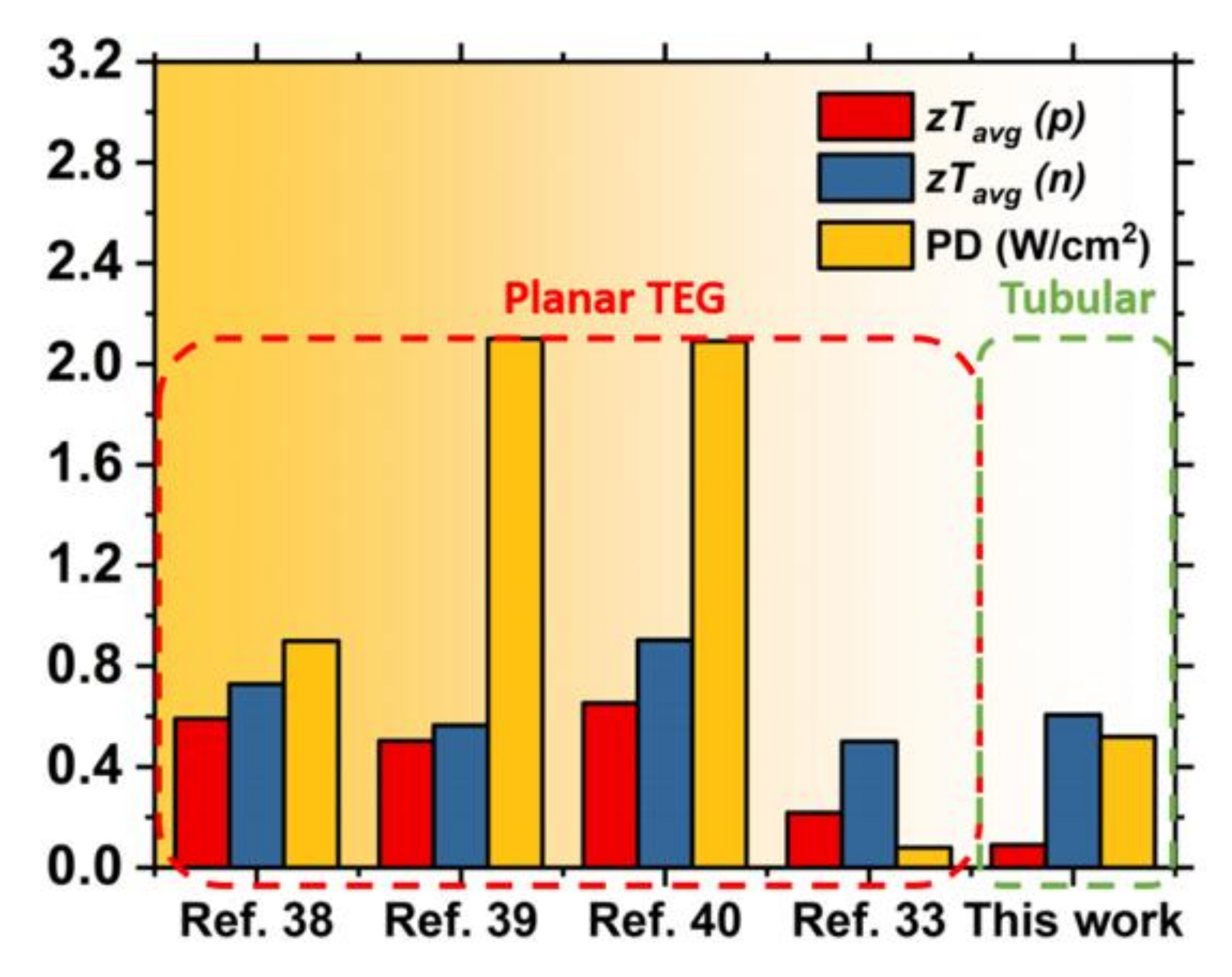
To show the usefulness of the MRW process for the fabrication of tubular TEG, we compared the power density and zTavg of other skutterudite-based modules to this work, as shown in Figure 5 [33,38,39,40]. Previous research methods employed high-performance TE material to the module, resulting in high zTavg, especially in the case of p-type. Even with such a huge mismatch between n- and p-type TE performance, the power density of the tubular module was comparable to that of planar TEGs. This suggests that the MRW process used in the fabrication of the SKD module enhanced performance.

4. Conclusions

We have demonstrated the use of modified resistance welding as a convenient joining method to fabricate thermoelectric generators (TEGs) with intricate tubular morphology, consequently leading to a record-breaking power density of 0.52 W/cm2 for the mid-temperature power generation. SEM microstructure confirms that the bonding interface is devoid of cracks or voids, resulting in the low specific contact resistance of 10−6 Ω·cm2. An evaluation of the power generation tests confirms that the MRW adopted in this work is suitable for fabricating the mid-temperature TE module. As such, there is plenty of room to improve the power density by adopting high-zT materials such as double-filled skutterudite, or incorporating a diffusion barrier between the TE material and the electrode. For this reason, we anticipate that this work could be a promising guideline for the fabrication of inorganic curved thermoelectric generators.

Supplementary Materials

The following are available online at https://www.mdpi.com/1996-1073/13/5/1106/s1, Table S1: comparison of electrode, joining method, specific contact resistance, and power density of the recently reported SKD-based thermoelectric generator. Figure S1: electrical resistance at the joining interface between the SKD and the Cu electrode, and detailed calculation of the resistance of the tubular thermoelectric generator.

Author Contributions

Conceptualization, M.-W.O.; Data curation, H.J., J.B.K. and M.-W.O.; Investigation, H.J., J.B.K., A.S., S.L., Y.K. and S.H.P.; Supervision, S.H.P., Y.S.J. and M.-W.O.; Writing—Original draft, H.J.; Writing—Review & editing, H.J., A.S., S.L., Y.S.J. and M.-W.O. All authors have read and agreed to the published version of the manuscript.

Funding

This work was supported by the National Research Foundation of Korea (NRF) Grant funded by the Korean Government (MSIP) (NRF-2015R1A5A1036133).

Conflicts of Interest

The authors declare no conflict of interest.

References

  1. Snyder, G.J.; Toberer, E.S. Complex thermoelectric materials. Nat. Mater. 2008, 7, 105–114. [Google Scholar] [CrossRef] [PubMed]
  2. DiSalvo, F.J. Thermoelectric cooling and power generation. Science 1999, 285, 703–706. [Google Scholar] [CrossRef] [PubMed]
  3. Tritt, T.M.; Subramanian, M.A. Thermoelectric Materials, Phenomena, and Applications: A Bird’s Eye View. MRS Bull. 2006, 31, 188–198. [Google Scholar] [CrossRef] [Green Version]
  4. Leoni, A.; Pantoli, L. SPICE Model Identification Technique of a Cheap Thermoelectric Cell Applied to DC/DC Design with MPPT Algorithm for Low-Cost, Low-Power Energy Harvesting. Appl. Sci. 2019, 9, 3744. [Google Scholar] [CrossRef] [Green Version]
  5. Stomelli, V.; Leoni, A.; Ferri, G.; Errico, V.; Ricci, M.; Pallotti, A.; Saggio, G. A Multi-Source Energy Harvesting Sensory Glove Electronic Architecture. In Proceedings of the 2018 3rd International Conference on Smart and Sustainable Technologies (SpliTech), Split, Croatia, 26–29 June 2018. [Google Scholar]
  6. Leoni, A.; Ulisse, I.; Pantoli, L.; Errico, V.; Ricci, M.; Orengo, G.; Saggio, G. Energy harvesting optimization for built-in power replacement of electronic multisensory architecture. AEU Int. J. Electron. Commun. 2019, 107, 170–176. [Google Scholar] [CrossRef]
  7. Park, K.T.; Shin, S.M.; Tazebay, A.S.; Um, H.D.; Jung, J.Y.; Jee, S.W. Lossless hybridization between photovoltaic and thermoelectric devices. Sci. Rep. 2013, 3, 2123. [Google Scholar] [CrossRef]
  8. Kil, T.H.; Kim, S.; Jeong, D.H.; Geum, D.M.; Lee, S.; Jung, S.J. A highly-efficient, concentrating-photovoltaic/thermoelectric hybrid generator. Nano Energy 2017, 37, 242. [Google Scholar] [CrossRef]
  9. Wei, T.; Huang, Y.H.; Zhang, Q.; Yuan, L.X.; Yang, J.Y.; Sun, Y.M. Thermoelectric Solid-Oxide Fuel Cells with Extra Power Conversion from Waste Heat. Chem. Mater. 2012, 24, 1401–1403. [Google Scholar] [CrossRef]
  10. Chen, X.; Pan, Y.; Chen, J. Performance and Evaluation of a Fuel Cell-Thermoelectric Generator Hybrid System. Fuel Cells 2010, 10, 1164–1170. [Google Scholar] [CrossRef]
  11. Liu, X.; Deng, Y.D.; Li, Z.; Su, C.Q. Performance analysis of a waste heat recovery thermoelectric generation system for automotive application. Energy Convers. Manag. 2015, 90, 121–127. [Google Scholar] [CrossRef]
  12. Temizer, I.; Ilkilic, C. The performance and analysis of the thermoelectric generator system used in diesel engines. Renew. Sustain. Energy Rev. 2016, 63, 141–151. [Google Scholar] [CrossRef]
  13. Kim, S.I.; Lee, K.H.; Mun, H.A.; Kim, H.S.; Hwang, S.W.; Roh, J.W. Thermoelectrics. Dense dislocation arrays embedded in grain boundaries for high-performance bulk thermoelectrics. Science 2015, 348, 109–114. [Google Scholar] [CrossRef] [PubMed] [Green Version]
  14. Goto, Y.; Nishida, A.; Nishiate, H.; Murata, M.; Lee, C.H.; Miura, A. Effect of Te substitution on crystal structure and transport properties of AgBiSe2 thermoelectric material. Dalton Trans. 2018, 47, 2575–2580. [Google Scholar] [CrossRef] [PubMed]
  15. Sadia, Y.; Ben-Ayoun, D.; Gelbstein, Y. Evaporation-condensation effects on the thermoelectric performance of PbTe-based couples. PhysChemChemPhys 2017, 19, 19326–19333. [Google Scholar] [CrossRef]
  16. Zhang, Q.; Zhou, Z.; Dylla, M.; Agne, M.T.; Pei, Y.; Wang, L. Realizing high-performance thermoelectric power generation through grain boundary engineering of skutterudite-based nanocomposites. Nano Energy 2017, 41, 501–510. [Google Scholar] [CrossRef]
  17. Ngan, P.H.; Han, L.; Christensen, D.V. Joining of Half-Heusler and Bismuth Tellurides for Segmented Thermoelectric Generators. J. Electron. Mater. 2018, 47, 701–710. [Google Scholar] [CrossRef] [Green Version]
  18. You, L.; Liu, Y.; Li, X.; Nan, P.; Ge, B.; Jiang, Y.; Snyder, G.J. Boosting the thermoelectric performance of PbSe through dynamic doping and hierarchical phonon scattering. Energy Environ. Sci. 2018, 11, 1848–1858. [Google Scholar] [CrossRef]
  19. Varghese, T.; Hollar, C.; Richardson, J.; Kempf, N.; Han, C.; Gamarachchi, P. High-performance and flexible thermoelectric films by screen printing solution-processed nanoplate crystals. Sci. Rep. 2016, 6, 33135. [Google Scholar] [CrossRef] [Green Version]
  20. Kim, F.; Kwon, B.; Eom, Y.; Lee, J.E.; Park, S.; Jo, S.; Min, T.S. 3D printing of shape-conformable thermoelectric materials using all-inorganic Bi2Te3-based inks. Nat. Energy 2018, 3, 301–309. [Google Scholar] [CrossRef]
  21. Menon, A.K.; Meek, O.; Eng, A.J.; Yee, S.K. Radial thermoelectric generator fabricated from n- and p-type conducting polymers. J. Appl. Polym. Sci. 2017, 134. [Google Scholar] [CrossRef]
  22. Merkulov, O.V.; Politov, B.V.; Chesnokov, K.Y.; Markov, A.A.; Leonidov, I.A.; Patrakeev, M.V. Fabrication and Testing of a Tubular Thermoelectric Module Based on Oxide Elements. J. Electron. Mater. 2018, 47, 2808–2816. [Google Scholar] [CrossRef]
  23. Min, G.; Rowe, D.M. Ring-structured thermoelectric module. Semicond. Sci. Technol. 2007, 22, 880–883. [Google Scholar] [CrossRef]
  24. Sakai, A.; Kanno, T.; Takahashi, K.; Tamaki, H.; Adachi, H.; Yamada, Y. Enhancement in Performance of the Tubular Thermoelectric Generator (TTEG). J. Electron. Mater. 2013, 42, 1612–1616. [Google Scholar] [CrossRef]
  25. Wang, X.; Li, B.; Yan, Y.; Liu, S.; Li, J. A study on heat transfer enhancement in the radial direction of gas flow for thermoelectric power generation. Appl. Therm. Eng. 2016, 102, 176–183. [Google Scholar] [CrossRef]
  26. Boriboonsomsin, K.; Durbin, T.; Scora, G.; Johnson, K.; Sandez, D.; Vu, A.; Dai, Z. Real-world exhaust temperature profiles of on-road heavy-duty diesel vehicles equipped with selective catalytic reduction. Sci. Total Environ. 2018, 634, 909–921. [Google Scholar] [CrossRef] [Green Version]
  27. Schmitz, A.; Stiewe, C.; Muller, E. Preparation of Ring-Shaped Thermoelectric Legs from PbTe Powders for Tubular Thermoelectric Modules. J. Electron. Mater. 2013, 42, 1702–1706. [Google Scholar] [CrossRef]
  28. Sakai, A.; Kanno, T.; Takahashi, K.; Tamaki, H.; Yamada, Y. Power Generation and Peltier Refrigeration by a Tubular pi-Type Thermoelectric Module. J. Electron. Mater. 2015, 44, 4510–4515. [Google Scholar] [CrossRef]
  29. Khovaylo, V.V.; Korolkov, T.A.; Voronin, A.I.; Gorshenkov, M.V.; Burkov, A.T. Rapid preparation of InxCo4Sb12 with a record-breaking ZT = 1.5: The role of the In overfilling fraction limit and Sb overstoichiometry. J. Mater. Chem. A 2017, 5, 3541–3546. [Google Scholar] [CrossRef] [Green Version]
  30. Tang, Y.; Gibbs, Z.M.; Agapito, L.A.; Li, G.; Kim, H.S.; Nardelli, M.B.; Snyder, G.J. Convergence of multi-valley bands as the electronic origin of high thermoelectric performance in CoSb3 skutterudites. Nat. Mater. 2015, 14, 1223. [Google Scholar] [CrossRef]
  31. Liu, W.S.; Zhang, B.P.; Li, J.F.; Zhang, H.L.; Zhao, L.D. Enhanced thermoelectric properties in CoSb3-xTex alloys prepared by mechanical alloying and spark plasma sintering. J. Appl. Phys. 2007, 102, 103717. [Google Scholar] [CrossRef]
  32. Chiu, W.T.; Chen, C.L.; Chen, Y.Y. A strategy to optimize the thermoelectric performance in a spark plasma sintering process. Sci. Rep. 2016, 6, 23143. [Google Scholar] [CrossRef] [PubMed] [Green Version]
  33. García-Cañadas, J.; Powell, A.V.; Kaltzoglou, A.; Vaqueiro, P.; Min, G. Fabrication and Evaluation of a Skutterudite-Based Thermoelectric Module for High-Temperature Applications. J. Electron. Mater. 2012, 42, 1369–1374. [Google Scholar] [CrossRef]
  34. Zhang, Q.H.; Huang, X.Y.; Bai, S.Q.; Shi, X.; Uher, C.; Chen, L.D. Thermoelectric Devices for Power Generation: Recent Progress and Future Challenges. Adv. Eng. Mater. 2016, 18, 194–213. [Google Scholar] [CrossRef]
  35. Oh, M.W.; Ahn, J.H.; Lee, J.K.; Kim, B.S.; Park, S.D.; Min, B.K.; Lee, H.W. Estimation of Power Generation from Thermoelectric Devices: Model Analysis and Performance Measurements. Electron. Mater. Lett. 2010, 6, 129–134. [Google Scholar] [CrossRef]
  36. Kim, H.S.; Liu, W.; Chen, G.; Chu, C.W.; Ren, Z. Relationship between thermoelectric figure of merit and energy conversion efficiency. Proc. Natl. Acad. Sci. USA 2015, 112, 8205. [Google Scholar] [CrossRef] [PubMed] [Green Version]
  37. Liu, Y.; García, G.; Ortega, S.; Cadavid, D.; Palacios, P.; Lu, J. Solution-based synthesis and processing of Sn- and Bi-doped Cu3SbSe4 nanocrystals, nanomaterials and ring-shaped thermoelectric generators. J. Mater. Chem. A 2017, 5, 2592–2602. [Google Scholar] [CrossRef] [Green Version]
  38. Prado-Gonjal, J.; Phillips, M.; Vaqueiro, P.; Min, G.; Powell, A.V. Skutterudite Thermoelectric Modules with High Volume-Power Density: Scalability and Reproducibility. ACS Appl. Energy Mater. 2018, 1, 6609–6618. [Google Scholar] [CrossRef]
  39. Park, S.H.; Jin, Y.; Cha, J.; Hong, K.; Kim, Y.; Yoon, H. High-Power-Density Skutterudite-Based Thermoelectric Modules with Ultralow Contact Resistivity Using Fe-Ni Metallization Layers. ACS Appl. Energy Mater. 2018, 1, 1603–1611. [Google Scholar] [CrossRef]
  40. Li, W.; Stokes, D.; Poudel, B.; Saparamadu, U.; Nozariasbmarz, A.; Kang, H.B.; Priya, S. High-Efficiency Skutterudite Modules at a Low Temperature Gradient. Energies 2019, 12, 4292. [Google Scholar] [CrossRef] [Green Version]
Figure 1. Temperature-dependent (a) Seebeck coefficient, (b) electrical conductivity, (c) thermal conductivity, and (d) dimensionless figure of merit of n-type (CoSb2.85Te0.15) and p-type (CoSb3) skutterudite used for the fabrication of the tubular thermoelectric generator (TEG) module.
Energies 13 01106 g001
Figure 2. Fabrication process of the tubular thermoelectric generator. (a) Preparation of sintered skutterudite (SKD) pellet. (b) Cutting out a hole into a center of the pellet. (c) Assembly of the components including electrodes, brazing sheets, insulating layers, and SKDs. (d) Modified resistance welding (MRW) method to mechanically join electrodes with SKDs. (e) Hierarchical structure of each component in the assembly of (c). (f) Photograph of the fabricated tubular thermoelectric generator with 4 pairs of SKDs. The scale bar in (f) is 10 mm.
Energies 13 01106 g002
Figure 3. Characterization of the joining interface between the SKD and the Cu electrode. (a,b) SEM image of the bonded interface between (a) n-type SKD and Cu electrode, and between (b) p-type SKD and Cu electrode with EDS (Energy-dispersive X-ray spectroscopy) line scan profile. (c,d) Measured specific contact resistance of (c) n-type side and (d) p-type side for various joining conditions. Region with black color in (c) and (d) means that no stable bonding is formed in this condition.
Energies 13 01106 g003
Figure 4. Output characteristic of the tubular thermoelectric generator. (a) Schematic of the experimental setup for measuring the output power of the module. (b) Measured open circuit voltage (VOC) of the module for various temperature differences. Ideal VOC, calculated from the material’s property, is drawn together. (c) Output power and (d) power density of the module. Recently reported power density of tubular TEGs at their operating temperature difference is plotted for the comparison [20,22,23,24,28,37].
Energies 13 01106 g004
Figure 5. Comparison of zTavg and power density of recently reported skutterudite-based conventional planar TEGs and our module. Despite the poor performance of p-type TE material, the power density of our module is higher than that of the planar TEGs, showing the advantage of the MRW process for the fabrication of tubular TEGs.
Energies 13 01106 g005