Abstract
The forthcoming implementation of the China VI emission regulations, which are currently the most stringent around the world targeted at light-duty gasoline engine vehicles, will not only further restrict the emissions of gaseous pollutants, but also put forward, for the first time, the requirements of particulate number (PN) emissions with a limit set at 6 × 10¹¹#/km. To achieve the stringent emission targets, the ceramic wall-flow gasoline particulate filter (GPF) will be effective to achieve the reduction of the particulate number tailpipe emissions in a way similar to the widely applied diesel particulate filter (DPF) in diesel engines. This paper investigated the effect of a coated gasoline particulate filter (GPF) on the PN emission and engine performance. The effects of two factors, including the washcoat powder material bulk density and type of coating, were studied with regard to three primary performances of GPF, including high three-way catalytic performance, low pressure drop, and high PN filtration efficiency, according to the original equipment manufacturer (OEM) requirements. The outcomes show that the use of high bulk density materials resulted in a low washcoat volume and hence a decrease of flow resistance and backpressure, in addition to high PN filtration efficiency. The type of coating had notable influence on the backpressure and PN filtration efficiency. The coating length and coating amount both had notable influence on the backpressure and PN filtration efficiency.
1. Introduction
In order to further improve engine fuel economy and reduce CO2 emissions, turbocharged gasoline direct injection (GDI) engines have prevailed as the power source for light-duty vehicles [1]. However, compared to vehicles equipped with traditional port fuel injection engines, GDI engines are known to have higher engine-out soot and particle number emissions, especially under cold start and high-speed, high-load operating conditions [2,3,4]. The latest China VI light-duty emission regulations will be implemented in 2020. For China VI, the certification test driving cycle will be changed from the New European Driving Cycle (NEDC) to the Worldwide Harmonized Light Vehicles Test (WLTC), which includes more transient operation points, leading to an increase of the maximum speed and acceleration, as well as a move to larger loads for engine operating regions [5]. Moreover, the pollutants limits will be substantially tighter. The particle number emissions requirement will be introduced in the China VI emission regulations for the first time, with the same limit set of 6 × 10¹¹#/km in the China VI-a and VI-b stages. In addition, the real driving emissions (RDE) certification test will be implemented in China VI-b stage in 2023, in which the conformity factor (CF) of the particulate number (PN) and NOx will be limited to be 2.1 and the CO2 emissions will be recorded. There is no doubt that the stringent requirements in China VI will be even more challenging for light-duty vehicles equipped with turbocharged GDI engines, especially in terms of meeting the PM/PN limit requirements.
For light-duty gasoline vehicles, in response to the upcoming implementation of the China VI emission regulations, advanced exhaust gas aftertreatment technologies (e.g., GPF) must be applied to reduce the vehicle tailpipe emissions in addition to the adaptation of engine internal parameters, such as air/fuel ratio, fuel injection strategy, and combustion phasing, to further optimize the combustion system in order to reduce the engine-out raw emissions [6,7,8,9]. The technology of DPF to solve the problem of diesel particulate emissions has been applied for many years, and its effectiveness on the reduction of particulate emission has been well confirmed [10,11]. It is considered that the use of GPF has the potential to effectively reduce gasoline particulate emissions over a wide range of engine operating conditions [12]. However, employing GPF as a solution to reduce particulate emissions also results in an increase of the pressure drop of the entire exhaust aftertreatment system. Consequently, the drop increases the backpressure of the exhaust manifold, and hence imposes a negative influence on the engine power output, fuel economy, and CO2 emissions [13].
In general, there are two types of particulate filters applied to the exhaust aftertreatment system currently: One is bare GPF without any catalyst coated, and the other is cGPF, which is coated with some amount of catalyst and could even further improve the three-way catalytic performance. Compared to the bare GPF, it is considered that adopting the coated GPF (cGPF) has more advantages, such as reducing the cost of substrates, packaging improvements, and an increase in soot regeneration performance under cold running conditions [14]. It is believed that the coated GPF will become the mainstream in auto original equipment manufacturers (OEMs) in the future. Coated GPF should fulfill design requirements in order to achieve sufficient particulate number filtration efficiency to meet the PN regulation limit. In the meantime, the pressure drop must be minimized to reduce its influence on engine power output and fuel economy. Different kinds of coatings with integrated pore characteristics of the filter wall were confirmed to have an evident effect on the reduction of the pressure drop and to increase PN filtration efficiency [15,16]. Consequently, this study concerned the coated GPF and describes the optimization design methodology. The results are discussed in detail in the subsequent sections.
2. Experimental Section
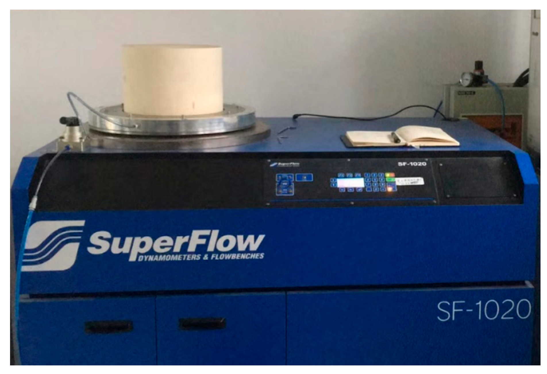
In this study, the influence of the pressure drop of the washcoat on the GPF were tested on a cold flow bench (computerized flowbench SF-1020 Probench), as can be seen from the Figure 1 and Table 1. The pressure drop of the test GPF samples was carried out on the SF-1020 Probench with 25 °C ambient temperature and an atmosphere pressure of 1 atm. Five air flow rates were studied, ranging from 200 kg/h to 600 kg/h at a step of 100. The GPF design was a cylinder with a diameter of 132.1 mm and a length of 127 mm. The cell structure was 300 cpsi/8 mil and the porosity was approximately 65%. Detailed parameters are listed in the Table 2.
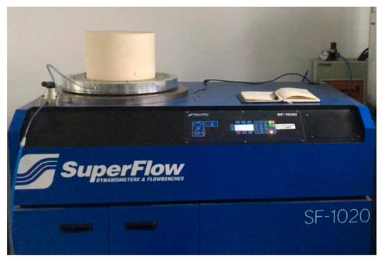
Figure 1.
Measurement equipment SF-1020 Probench.

Table 1.
Measurement conditions of the pressure drop on the gasoline particulate filter (GPF).
Table 2.
Measurement conditions of the pressure drop on the GPF.
In this study, the influence of the particle number filtration and gas pollutant abatement efficiency of the washcoat on the GPF were tested on a light-duty passenger car, equipped with 1.4-liter displacement turbocharged gasoline direct-injection (TGDI) engine, which was employed for the on-engine experiment at test driving cycle Worldwide harmonized Light vehicles Test Cycle (WLTC) on vehicle emission hub of HORIBA test equipment. The tests used China VI emission regulation 92 # gasoline, as can be seen from the Figure 2. The information of the test engine and the washcoat are shown in Table 3.
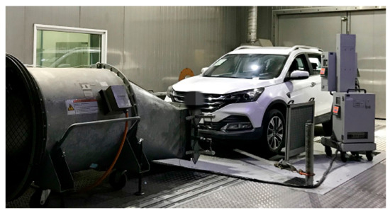
Figure 2.
Tests of the particulate number filtration and efficiency.
Table 3.
Main parameters of the test vehicle.
3. Results and Discussion
3.1. Washcoat Powder Material Bulk Density
The effects of washcoat powder material bulk density on gasoline particulate filter performance were first studied. In order to study the factor, the catalyst coating amount was kept constant at 100 g/L. In the meantime, the bulk density of powder material of the washcoat was changed by adjusting the percentage of composition of the powder. Two kinds of compositions were employed in the study, namely aluminum oxide and cerium zirconium composite oxides. Two types of powder with different bulk densities, referred to as GPF-A and GPF-B, were investigated. Detailed information of the powders is listed in the Table 4. As listed in Table 4, GPF-A represents the washcoat, which used low-level bulk density material. The percentage of the aluminum oxide was 0.37 g/mL and the cerium zirconium was 0.27 g/mL. On the other hand, GPF-B represents the high-level bulk density material washcoat, with 0.76 g/mL and 0.55 g/mL for the two materials. For the convenience of comparison, GPF-Ref represents a commercial GPF with same catalyst coating amount.
Table 4.
Comparison of bulk density of GPF-A and GPF-B (g/mL).
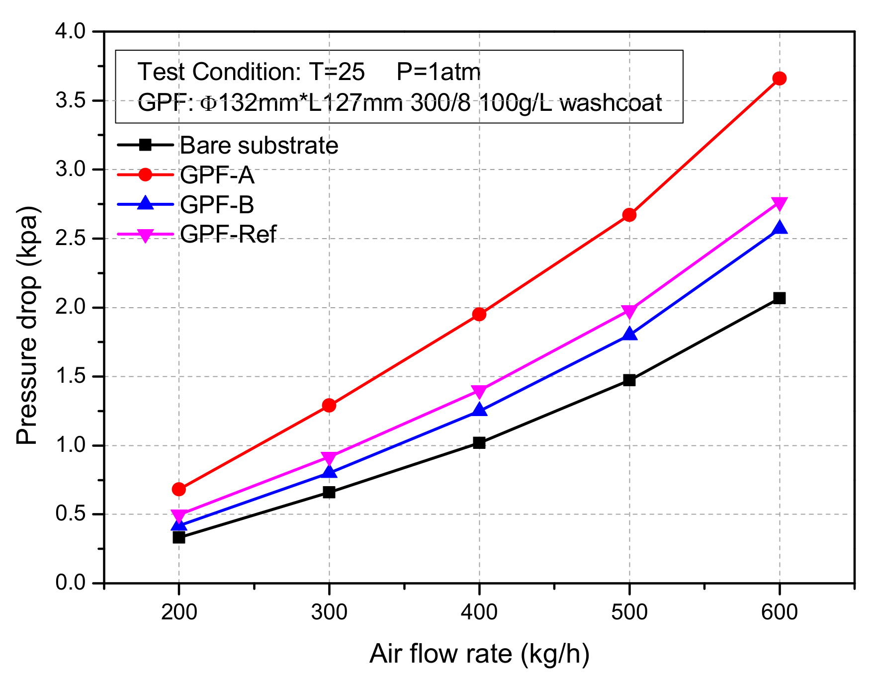
The pressure drop of test GPF samples against the air flow rate is plotted in Figure 3. It can be seen from the Figure 3 that the pressure drop of the GPF-B in the whole test flow range was about 34.9% lower than that of the GPF-A, and 11.1% lower than that of the commercial GPF-Ref. As can be seen from Table 2, the bulk density of the powdery material used in the GPF-B was about twice as high as that of GPF-A. Therefore, the washcoat volume of former coating was smaller than that of the latter under the same coating amount. Consequently, the type of washcoat with a smaller volume avoided extensive build-up in the pores of the substrate, and hence reduced flow resistance. Eventually, it led to a decrease in pressure drop.

Figure 3.
Influence of washcoat material bulk density on pressure drop.
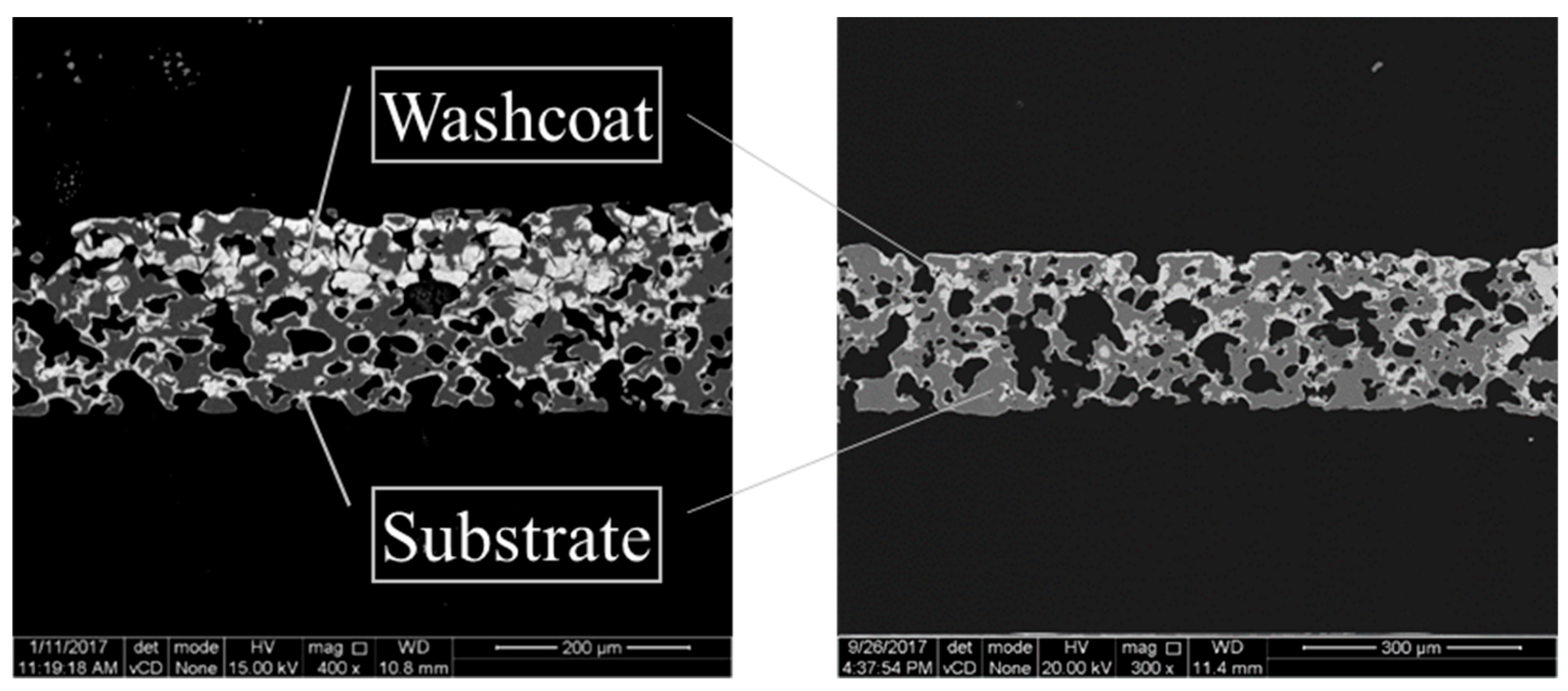
In order to further check the influence of bulk density on the pressure drop, the microstructure of the GPF washcoat was characterized by scanning electron microscope (SEM). The images of the two types of coating are seen in Figure 4. The white part in the figure represents the washcoat, and the dark grey part represents the substrate. As described above, the washcoat in GPF-A showed extensive piling up, especially on one side of the substrate, which had a great hindering effect on the gas flow. As the material bulk density increased, the washcoat of GPF-B had a lower volume and appeared to accumulate very little. Hence, the flow resistance of GPF-B was obviously lower than GPF-A, as confirmed in pressure drop test.
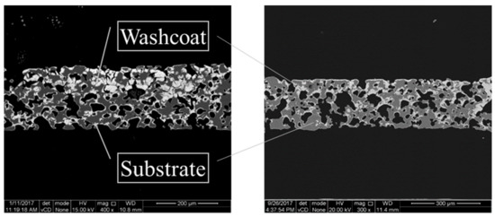
Figure 4.
SEM images of the GPF samples of GPF-A and GPF-B.
The results of fresh state PN efficiency by the two types of washcoat are shown in Figure 5. It can be seen that the efficiency was significantly improved by both washcoats, further confirming the effectiveness of the washcoat on the reduction of particle emission. More importantly, compared with GPF-A, the PN filtration efficiency of GPF-B slightly increased by about 2.9% after raising the bulk density of the coating material. More dispersed distribution of the inner coating in the large pores by application of high bulk density coating material is considered to be the reason for the higher PN filtration efficiency.
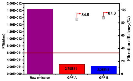
Figure 5.
Influence of the washcoat material bulk density on particulate number (PN) filtration efficiency.
In order to check the influence of the bulk density on the light-off temperature on the emission of gasoline engine, the results of CO/HC/NOx light-off temperature (T50) of engine bench test of GPF-A and GPF-B are further shown in Figure 6. It can be confirmed that the coating material bulk density had little impact on CO/HC/NOx light-off temperature.
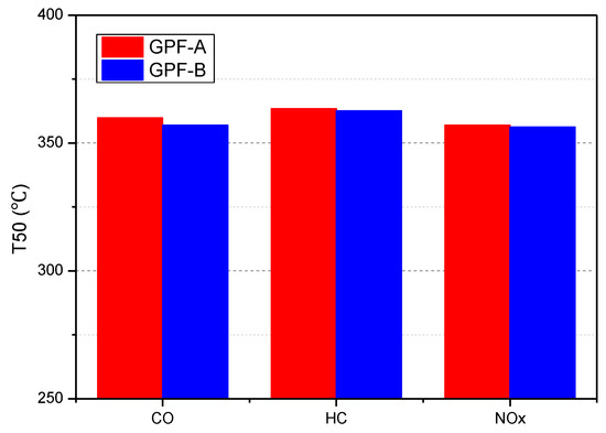
Figure 6.
Influence of coating material bulk density on T50 of CO/HC/NOx.
3.2. Catalysts Coating
In addition to the material of the washcoat on GPF performance, the impact of catalyst coating on GPF performance was also studied. Two factors, namely the direction and the length of the coating, were investigated via experiment. The catalyst coating amount was kept constant (approx. 100 g/L) for fair comparison. The test samples were prepared in four different types of coating using the S-75% and S-100% to represent single-side coating with 75% and 100% of substrate length for coating length, respectively, whereas T-50% and T-75% represent two-side coating with 50% and 75% of substrate length for coating length, respectively. The sketches of different catalyst coating are shown in Figure 7.
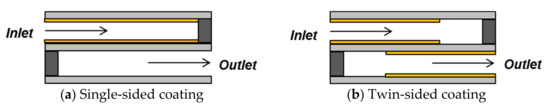
Figure 7.
Diagram of two different catalyst coating of GPF.
The experiment boundary conditions for the measurements and procedure are same as Table 1. The experimental test was carried out on the cold flow bench with 25 °C ambient temperature and an atmosphere pressure of 1 atm. The four catalysts coating tested were S-100%, S-75%, T-50%, and T-75%.
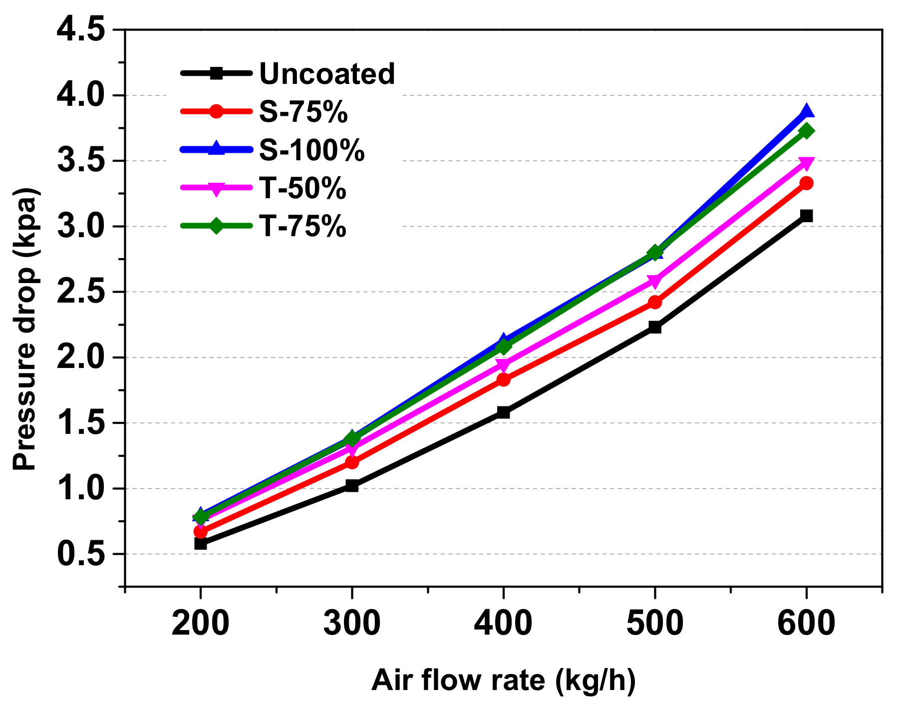
The pressure drop, with four different kinds of catalyst coatings against air flow rate, is plotted in Figure 8. It can be seen that catalyst coating had moderate influence on the pressure drop, including the coating direction and coating length. First, all the coatings increased the pressure drop at each flow range. Moreover, the pressure drop of the S-100% was the highest in the whole flow range in the test, followed by T-75%, T-50%, and S-75%. Different coatings had a great influence on the distribution of the coated washcoat in the interior of GPF. The T-75% coating did not only make the washcoat cover the inlet and outlet wall of substrate more uniformly, but also increased the washcoat density per length, resulting in the highest pressure drop. For the S-100% coating, it was not easy to control the coating process operation because it was prevent the penetration of the washcoat throughout the S-100% length-coating process, and it was also difficult to guarantee the uniformity of the coated washcoat. The T-50% coating did not only greatly reduce the pressure drop, but was also easy to be controlled for coating. In addition, better uniformity and distribution of the coated washcoat can also be achieved by this coating. Although the pressure drop was the lowest for the S-75% coating, a blank of 25% length was left to the substrate, which largely affected the PN filtration efficiency.

Figure 8.
Influence of catalysts coating on GPF cold flow pressure drop.
Furthermore, series of WLTC emission tests were conducted to determine the impact of several different catalyst coatings on PN filtration efficiency. Figure 9 shows the results of the fresh state PN filtration efficiency of four different kinds of catalyst coating. Corresponding to the results of the pressure drop, the T-75% coating had the highest PN filtration efficiency, reaching more than 95%. The PN filtration efficiency of S-100% and T-50% coatings, respectively, were about 92% and 89%, while the S-75% had the lowest PN filtration efficiency with approximately 85%. It can be concluded that the pressure drop is positively correlated with the PN filtration efficiency after further comprehensive analysis in terms of influence of different coatings on pressure drop and PN filtration efficiency. Based on the principle that the pressure drop should be reduced as much as possible on the premise of the PN filtration efficiency to meet development requirements, the T-50% was determined the optimum catalyst coating.
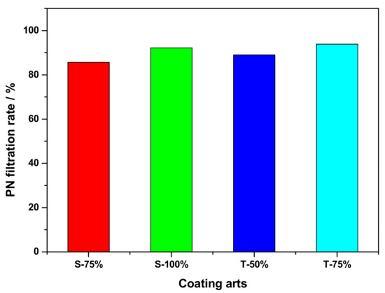
Figure 9.
Influence of catalyst coatings on PN filtration efficiency.
4. Conclusions
In this study, the washcoat for a gasoline particulate filter (GPF) was experimentally studied. The influence of material selection and different kinds of coatings on the pressure drop, PN filtration efficiency, and three-way catalytic performance were examined. The two main conclusions were drawn as follows:
- The bulk density of powder materials employed in GPF washcoat had a great influence on the backpressure. High bulk density materials resulted in a low washcoat volume and hence the decrease of flow resistance and backpressure. The PN filtration can also be improved using high bulk density powder materials due to the more dispersed distribution of the inner coating.
- The kind of different coatings, which included coating directions, coating length, and coating amount, had notable influence on the backpressure and PN filtration efficiency. T-50% has been experimentally confirmed as the optimum catalyst coating, which meets both the lower backpressure and PN filtration ratio that fulfilled the development requirements.
Author Contributions
Conceptualization, J.W. and F.Y.; Methodology, J.W. and Y.W.; Validation, J.W.; Investigation, N.F and W.Y.; Data Curation, N.F.; Writing—Original Draft Preparation, J.W.; Writing—Review & Editing, N.F., D.Y. and G.Z.; Supervision, F.Y.; Project Administration, F.Y. All authors have read and agreed to the published version of the manuscript.
Funding
This research was funded partially by the National Key R&D Program of China (2017YFC0211201).
Conflicts of Interest
The authors declare no conflict of interest.
Abbreviations
| PN | Particulate Number |
| PM | Particulate Matter |
| GDI | Gasoline Direct Injection |
| RDE | Real Driving Emissions |
| GPF | Gasoline Particulate Filter |
| PFI | Port Fuel Injection |
| NEDC | New European Driving Cycle |
| DPF | Diesel Particulate Filter |
| MPS | Mean Pore Size |
| AFR | Air Fuel Ratios |
| PGM | Platinum Group Metals |
| TWC | Three-Way-Catalyst |
| WLTC | Worldwide harmonized Light vehicles Test Cycle |
| SEM | Scanning Electron Microscope |
References
- Caggiano, M. Technology road map in the next decade for gasoline engine. In Proceedings of the 8th International Conference Powertrain Technologies for CO2, ATA 2010, Turin, Italy, 17–18 November 2010. [Google Scholar]
- Berkemeier, O.; Grieser, K.; Hohenboeken, K.; Karvounis, E.; Springer, K.M. Strategies to Control Particulate Emissions of Gasoline Direct Injection Engines. In Proceedings of the FISITA 2012 World Automotive Congress, Beijing, China, 27–30 November 2012. [Google Scholar]
- Chan, T.W.; Meloche, E.; Rosenblatt, D.; Kubsh, J.; Brezny, R.; Rideout, G. Reducing Particulate Emissions for Future Gasoline Direct Injection Vehicles with a Gasoline Particulate Filter. In Proceedings of the ETH Conference on Combustion Generated Nanoparticles, Zürich, Switzerland, 24–27 June 2012. [Google Scholar]
- Friedrich, A. Particles from Gasoline Direct Injection Engines: Abatement Options. In Proceedings of the ETH Conference on Combustion Generated Nanoparticles, Zürich, Switzerland, 23–26 June 2013. [Google Scholar]
- Limits and Measurement Methods for Emissions from Light-Duty Vehicles (CHINA 6). 23 December 2016. Available online: http://www.mee.gov.cn/ywgz/fgbz/bz/bzwb/dqhjbh/dqydywrwpfbz/201612/W020171207355626647621.pdf (accessed on 31 January 2020).
- Piock, W.; Hoffmann, G.; Berndorfer, A.; Salemi, P.; Fusshoeller, B. Strategies Towards Meeting Future Particulate Matter Emission Requirements in Homogeneous Gasoline Direct Injection Engines. SAE Int. J. Engines 2011, 4, 1455–1468. [Google Scholar] [CrossRef]
- Heiduk, T.; Stichlmeir, M.; Unselt, F.; Kuhn, M. The New 1.8L TFSI Engine from Audi-Part 2: Mixture Formation, Combustion Method and Turbocharging. MTZ Worldw. eMag. 2011, 72, 58–64. [Google Scholar] [CrossRef]
- Klauer, N.; Kluting, M.; Schunemann, E.; Schwarz, C.; Steinparzer, F. BMW Twin Power Turbo Gasoline Engine Technology-Enabling Compliance with worldwide Exhaust Gas Emission Requirements. In Proceedings of the 34th International Vienna Motor Symposium, Vienna, Austria, 25–26 April 2013. [Google Scholar]
- Merdes, N.; Enderle, C.; Vent, G.; Weller, R. The New Turbocharged Four-cylinder Gasoline Engine by Mer-cedes-Benz. MTZ Worldw. eMag. 2011, 72, 16–23. [Google Scholar] [CrossRef]
- Ohara, E.; Mizuno, Y.; Miyairi, Y.; Mizutani, T.; Yuuki, K.; Noguchi, Y.; Hiramatsu, T.; Makino, M.; Takahashi, A.; Sakai, H.; et al. Filtration Behavior of Diesel Particulate Filters (1). SAE Tech. Pap. 2007. [Google Scholar] [CrossRef]
- Richter, J.; Klingmann, R.; Spiess, S.; Wong, K. Application of Catalyzed Gasoline Particulate Filters to GDI Vehicles. SAE Int. J. Engines 2012, 5, 1361–1370. [Google Scholar] [CrossRef]
- Saito, C.; Nakatani, T.; Miyairi, Y.; Yuuki, K.; Makino, M.; Kurachi, H.; Heuss, W.; Kuki, T.; Furuta, Y.; Kattouah, P.; et al. New Particulate Filter Concept to Reduce Particle Number Emissions. SAE Tech. Pap. 2011. [Google Scholar] [CrossRef]
- Shimoda, T.; Ito, Y.; Saito, C.; Nakatani, T.; Shibagaki, Y.; Yuuki, K.; Sakamoto, H.; Vogt, C.; Matsumoto, T.; Furuta, Y.; et al. Potential of a Low Pressure Drop Filter Concept for Direct Injection Gasoline Engines to Reduce Particulate Number Emission. SAE Tech. Pap. 2012. [Google Scholar] [CrossRef]
- Inoda, S.; Nomura, Y.; Ori, H.; Yabuzaki, Y. Development of New Coating Technology Optimized for Each Function of Coated GPF. SAE Tech. Pap. 2017. [Google Scholar] [CrossRef]
- Ogyu, K.; Ogasawara, T.; Nagatsu, Y.; Yamamoto, Y.; Higuchi, T.; Ohno, K. Feasibility Study on the Filter Design of Re-Crystallized SiC-GPF for TWC Coating Application. SAE Tech. Pap. 2015. [Google Scholar] [CrossRef]
- Ito, Y.; Shimoda, T.; Aoki, T.; Yuuki, K.; Sakamoto, H.; Kato, K.; Thier, D.; Kattouah, P.; Ohara, E.; Vogt, C. Next Generation of Ceramic Wall Flow Gasoline Particulate Filter with Integrated Three Way Catalyst. SAE Tech. Pap. 2015. [Google Scholar] [CrossRef]


© 2020 by the authors. Licensee MDPI, Basel, Switzerland. This article is an open access article distributed under the terms and conditions of the Creative Commons Attribution (CC BY) license (http://creativecommons.org/licenses/by/4.0/).