1. Introduction
In a world where the energy demand grows more and more both in developed and emerging countries, the efficient utilization of energy is one of the key topics for the reduction of overall consumption and environmental protection. As reported in the International Energy Agency (IEA) report published in 2016 [
1], from 2000 to 2015 the avoided energy consumption connected with energy efficiency improvements led to a cumulative saving of 13 GtCO
2 (more than the emissions of all IEA countries in 2015). Moreover, energy saving reduces infrastructure investment requirements for additional demands. In the last years, energy policies with stringent targets (in some cases very challenging) were adopted by major countries to improve energy savings in the medium and long term. To mention some relevant examples, the European Union established an energy efficiency target of 32.5% by 2030 [
2], while China set an ambitious target combining carbon intensity and energy consumption reductions with the 13th Five-Year Plan [
3].
As reported in the last IEA report [
4], the results of energy policies adopted by countries reflect in reduced global expenditure on energy due to efficiency improvements which were almost USD 600 billion from 2000 to 2018, about one third related to industrial sectors. Notwithstanding, thinking of industry, the waste heat potential not exploited yet is remarkable. In Papapetrou et al. [
5], a detailed estimation of industrial waste heat in Europe is reported. In particular, the total amount of the European Union industrial waste heat potential was evaluated at almost 300 TWh/year, one third with a temperature level below 200 °C, one fourth in the range of 200–500 °C and the remaining at higher temperatures.
Bruckner et al. [
6] summarize the available waste heat per-process in Germany and categorize waste heat recovery technologies. It can be noted that many sectors make available waste heat at medium temperature (100–400 °C) (e.g., food and tobacco, paper, chemicals) which could be used for power production. The higher the WH temperature is, the more efficient the heat to power conversion is. In the medium-temperature range, such recovery and conversion can be done by means of organic Rankine cycle (ORC) systems.
Tartiere et al. [
7] provide a global overview of the ORC market worldwide. In particular, they report data per application and manufactures, showing that in 2017 a total capacity of 376 MW was installed for the Waste Heat Recovery (WHR) and most of them were covered by medium-large ORC plants. Even though the industrial WHR is the second market for ORCs (8.8%), such data mean that a large amount of available heat potential has not been exploited yet, mainly where small units (< 100 kWe) could be applied. Nowadays, several manufacturers have been developing small ORC plants, but the development of efficient and cost-effective products that allow short payback times in a wide range of applications is a very challenging target. Firstly, it is due to intrinsic thermodynamic limits (mentioned in
Section 2) which reduce the theoretical cycle efficiency and consequently, the economic feasibility of the recovery system. Therefore, key components, as the expander, need to be selected/developed carefully to avoid further penalties on the system performance.
This paper is focused on the design (from a 1-D to a fully 3-D level) of a novel two-stage radial-inflow turbine with a total power output less than 100 kW starting from the experience gained with the design and analysis of a single-stage turbine. Each stage was preliminarily designed by conventional 1D methods. Afterward, overall stage performances were investigated by means of ANSYS-CFX, the Computational Fluid Dynamic (CFD) software delivered by ANSYS, Inc. (USA) devoted to numerical fluid dynamic analysis inside turbomachines. The improvement of the stage’s performance was carried out iteratively, varying the most relevant geometric parameters and the most promising geometries were stacked together and analyzed in nominal and off-design conditions.
The paper is made up of six sections, including this introduction. In the second section, a general description of the plant layout and the selection of the most suitable expander option on the basis of a detailed review are reported. The third chapter is focused on methodological approaches adopted for the expander preliminary (1D/2D) and detailed (3D) designs. Design results are presented and discussed in the fourth chapter, while the stage analysis and stacking are reported in the fifth section. Concluding remarks and further research activities are summarized in the final section.
2. Selection of the Expander Configuration for the Reference ORC Plant
ORC plants are based on the Rankine cycle principle, but the working fluid (WF) is organic instead of water like in a steam power plant. Many advanced cycles and plant architectures have been designed to maximize the thermodynamic system efficiency for WHR applications. However, the complexity of some of them or the lack of experimental data makes them unattractive at present from an economic point of view as reported in [
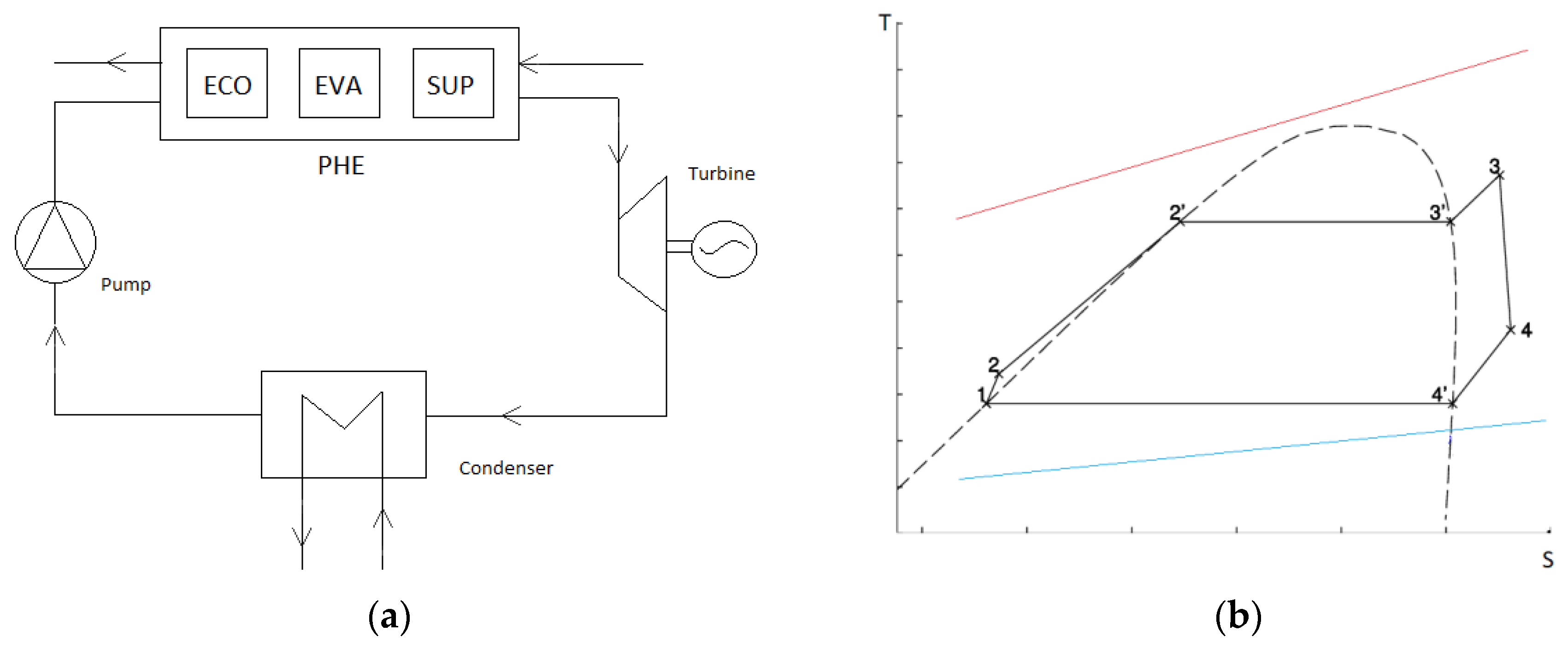
8]. For small scale applications, where an acceptable payback time can be hard to be reached, the authors decided to adopt a simple reference layout with a recovery system. The basic scheme is depicted in
Figure 1a, while the reference Rankine cycle is illustrated in
Figure 1b. The main components are:
A primary heat exchanger (PHE), made up of an economizer (ECO), an evaporator (EVA), and a superheater (SUP). The PHE transfers the thermal power from the high-temperature heat source to the ORC plant. The WF evaporates during this transformation, and it is usually overheated
A turbine that extracts mechanical power from the WF. In this study, the two-stage turbine and the generator are connected by an integrally-geared configuration
A condenser that rejects the thermal power into an external low-temperature heat source, cooling and condensing the WF
A pump to increase the WF pressure from the condensation to the evaporation one
Sometimes in the plant, there is a recuperator to pre-heat the WF before entering the PHE using part of the heat rejected by the WF at the turbine exit. In this case, a recuperator could recover a small amount of heat; therefore, it was not taken into consideration
The preliminary techno-economic analysis can be carried out according to methodologies described in [
9]. In addition to the boundary conditions fixed by the available primary heat source, the selection of the most appropriate WF is a mandatory aspect to be taken into consideration. Darvish et al. [
10] reviewed the best candidates for each application by the exergo-economic point of view. In detail, the WF selection depends on several thermodynamic and environmental properties. Bao and Zhao [
11] pointed out the main thermodynamic and physical properties of dry WFs which affect performances of ORC plants. The selection shall fit with the heat source temperature. WF latent heat, density, specific heat, critical temperature, molecular weight, complexity and conductivity are identified as crucial properties to be taken into consideration for the evaluation of the cycle performance. In the end, the authors give relevant information based on condensation and evaporation temperatures and on the type of expander. As reported in [
12], the interaction between the WF and heat carrier becomes relevant, especially in WHR and geothermal applications. More WF properties need to be considered in the plant economic assessment where, in the first instance, the analysis can be focused on heat exchangers (heat transfer area) since most of the capital costs are related to such components.
Song and Gu [
13] focused their attention on how the WF selection affects ORC parameter determination and, mainly, the turbine efficiency, and highlighted the WF role in the setup of an efficient system.
For the WHR case considered for this work, the WF is R123. Although such a fluid is a refrigerant, it also shows interesting thermodynamic and fluid-dynamic properties for medium-temperature Rankine cycles. The present study is based on detailed data reported in Refprop v9 [
14].
In a previous work of the research group [
15], the techno-economic and life cycle analyses of three different small-scale (< 100 kWe) ORC plants for this case study were presented. They differ from each other in the expander technology (twin-screw expander, single and two-stage radial turbines). Indeed, for such applications, several types of expanders could be adopted as reported by Rahbar et al. [
16] and Tocci et al. [
17]. Saghlatoun, S. et al. [
18] focused their attention on how to select this key component correctly. In any case, there are several constraints that limit the expander capabilities and affect plant performance at nominal and off-design conditions. Usually, positive displacement expanders are preferred for small sizes. However, the expander volume ratio limits the gap between system evaporating and condensing pressures considerably. For instance, for screw machines, this value rarely exceeds 5 [
19,
20]. If the imposed system’s pressure ratio is higher than that related to the expander configuration, an under- or over-expansion occurs at the machine exit, increasing considerably thermodynamic losses in the system. Even turbines show a limit on the manometric pressure ratio, which they can allow for each stage to contain fluid-dynamic losses in a reasonable range. Usually, organic fluid’s sound speed is quite low (around 115–130 m/s in the turbine operating range). It penalizes the stage pressure ratio because transonic/supersonic flow conditions should be avoided at the machine exit in order to limit component (and system) efficiency drops. Consequently, the specific work per stage is limited. Transonic machines can be adopted [
21], although wake and kinetic losses are unavoidable for such turbines, and chocked conditions reduce the component flexibility. Despite this, small radial turbomachines are generally more robust and cheaper than volumetric machines, in the past, for small applications, positive displacement machines were preferred to dynamic ones since their rotational speed is lower under the same boundary conditions. In the last years, the development of permanent magnet generators with a variable frequency drive makes viable novel high-speed solutions without a mechanical gearbox. Thereby, costs can be reduced and system reliability improved.
In [
15], it was concluded that taking into consideration the same waste heat potential, a plant equipped with a two-stage radial turbine showed the best techno-economic performance due to the increase of the overall nominal pressure ratio. Therefore, for the present study, a two-stage radial inflow turbine was designed referring to the plant analyzed in the previous work [
15]. The outlet pressure was fixed at 2.4 bar (condensation temperature 52 °C) for a good balance between high specific work and low velocities. Turbine inlet conditions (17.5 bar and 145 °C) and nominal WF mass flow rate (3.37 kg/s) were evaluated previously in [
15]. Since the maximum thermodynamic efficiency of the recuperated cycle is almost 16.8%, components need to be designed carefully to keep from reducing plant performances both at nominal and off-design conditions any longer.
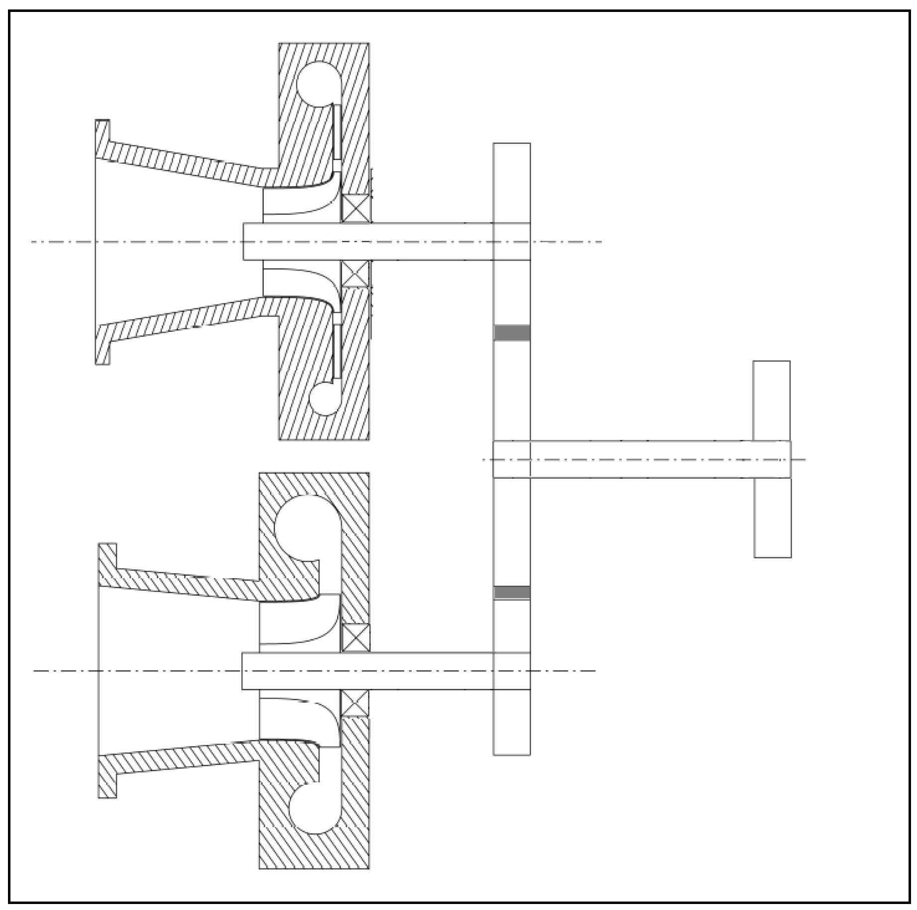
The proposed turbine is made of two radial stages (high-pressure and low-pressure turbines, HPT and LPT, respectively) in an integrally-geared configuration usually adopted for industrial radial turbomachines [
22]. A simplified sketch of the system is shown in
Figure 2. Such configuration enables the selection of the best rotational speed for each stage together with the connection to a lower speed electric generator. For this study, a synchronous generator was taken into consideration; therefore, the rotational speed for both stages is fixed in the overall operational range. Other layouts, more innovative, could be taken into consideration. For instance, the compact single-shaft configuration proposed by Kang [
23] is one of them. Nonetheless, despite its compactness and flexibility, several aspects concerning generator arrangement and bearings selection need to be further investigated.
The following Chapter describes in detail the methodology followed for the design of high-pressure turbine (HPT) and low-pressure turbine (LPT). The design procedure was applied iteratively to establish the shaft rotational speed and to achieve a trade-off in the expected stages nominal performance. Then, parametric analyses were carried out to upgrade preliminary geometries.
3. Turbine Design Methodology
Unconventional WFs, as ORC fluids, pose several concerns for the turbomachinery design process [
24]. For instance, R123 shows a higher specific volume increase through the expansion than conventional gases (e.g., air, exhausted gases). Furthermore, the speed of sound in organic fluids is considerably lower than in WFs commonly utilized (about 100–150 m/s). Consequently, the preliminary design cannot be completely based on dimensionless charts and semi-empirical correlations available in literature [
25]. Although several researchers tried to address this challenging technical aspect [
26,
27,
28], the uncertainty related to the application of global models in the design process of ORC turbines leads to more detailed procedures which involve a preliminary layout setup (1-D and 2-D models at the mean line) and then, the utilization of fully 3-D numerical analyses. With respect to small ORC radial turbomachines, previous applications of such design methodology are reported in Giovannelli et al. [
29,
30].
The 1-D preliminary design of both stages was performed using an in-house tool developed in Fortran 90 for radial-inflow expanders. The tool implements governing equations and specific work (Euler’s equation) for a steady and adiabatic turbomachine as follows:
Euler work (Momentum equation)
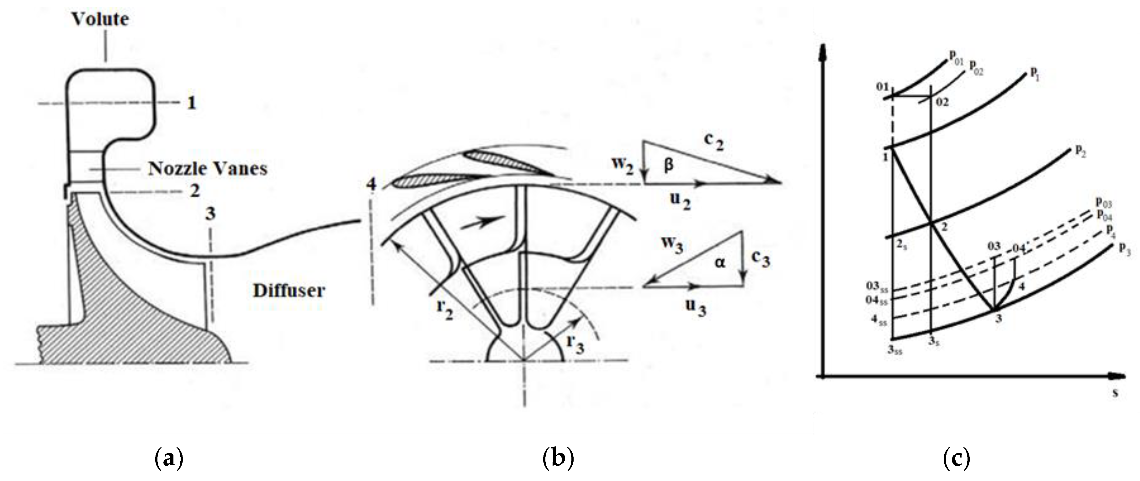
Absolute velocities (
cj), relative velocities (
wj), and rotor speeds (
uj) at the mean-line are correlated to each other by the velocity triangles depicted in
Figure 3.
αj and
βj are the absolute and relative angles, respectively.
WF stagnation and static thermodynamic properties at the mean-line for each section are evaluated, implementing in the tool data from REFPROP v9 [
14].
Semi-empirical correlations were adopted for a preliminary prediction of the performance of the two stages and, consequently, for the evaluation of blade angles at the mean-line and main sections’ areas. On the basis of geometrical parameters reported in
Figure 3, the following relationships were applied in the model:
The empirical equation adopted to calculate the number of blades was given by Rohlik [
31]
For the first stage, the preliminary number of nozzle vanes was taken as NR+1 to avoid common divisor.
The slip factor (
σ) reflects the imperfect working fluid guidance from the rotor vanes, modifying exchanged work and average fluid direction at the rotor exit. It was evaluated by the simplified equation reported in Aungier [
32]:
being
β3c the mean-line blade angle at the rotor exit.
Friction losses in the rotor were preliminary evaluated by an enthalpy loss coefficient as expressed in [
33]
being
φR the velocity coefficient
Friction losses in the nozzle, including at this stage, also inlet scroll losses were considered by a loss coefficient similar to the rotor one [
33]:
being
φN is the velocity coefficient
φR and
φN were selected in the normal range of well-designed radial machines.
Although previous correlations were derived experimentally for turbomachines operating with conventional fluids, they are widely used in literature for the preliminary design of organic turbomachinery [
34,
35,
36,
37].
In the preliminary 1D stage design procedure, incidence and tip clearance losses were neglected, while windage losses were taken into consideration using the relationship given by [
38]
The geometry of the main stage sections, reported schematically in
Figure 3, is fixed according to blade speed, expected velocity triangles, and WF average density for each of them.
Once the stages were preliminary designed, the numerical CFD three-dimensional analysis at the design point was carried out using the commercial software ANSYS-CFX [
39]. Such software implements the general conservation laws (mass, momentum, and energy) using the full system of Navier-Stokes (N-S) equations for viscous flows. As the final aim of the analysis was an estimation of the whole components’ performance, a quasi-steady analysis was conducted. Therefore, the N-S system was treated in a simplified way by Reynolds-averaged-Navier-Stokes equations discretized by a hybrid Finite Volume (FV) /Finite Element (FE) approach. Specifically, local conservation over control volumes is satisfied as in FV methods, and some surface fluxes and source terms are evaluated as in FE approaches. Advection fluxes are solved using a second-order advection scheme [
40]. The standard k-ε turbulent model with a scalable wall function was selected to simulate both stages of the turbine. A multiple frame approach was selected: the flow was assumed steady in the appropriate frame of reference both in stationary and moving frames. In particular, in moving sub-domains, some additional terms (centrifugal, Coriolis) are added into the momentum equation since the sub-domain is not inertial. The “frozen rotor” technique provides a local coupling between adjacent sub-domains (stationary/moving ones) converting relative velocities in moving frames into absolute velocities in stationary frames and vice-versa.
To lower the computational effort, a reduced number of blade/vane channels were modeled, taking advantage of the radial symmetry of the machines and imposing periodic boundary conditions. Therefore, an H-O-H mesh for a limited number of rotor and vane channels was generated. A structured mesh for each channel was set, and the overall mesh quality parameters (maximum and minimum face angles, edge length ratio, element volume size) have been checked to provide good accuracy. A grid independence analysis for each stage component was carried out as presented in the following chapter.
The real gas cubic equation Aungier-Redlich-Kwong Model [
41] was chosen to describe the WF properties. Such a model provides a reasonable prediction of the real fluid behavior in cases of interest.
Normalized residuals were monitored during the solution process. In particular, they were calculated as the imbalance in the linearized system of discrete equations. Convergence criteria were considered reached for residuals lower than 10−4.
4. Turbine Design
The radial-inflow two-stage expander was designed iteratively, using the aforementioned 1D models. First of all, HPT and LPT nominal shaft speeds were evaluated, maintaining main adimensional parameters (i.e., specific speed, specific diameter, flow coefficients) in the recommended ranges given in the literature. Finally, 23,000 rpm and 27,000 rpm were fixed for HPT and LPT, respectively. Once the expansion ratio was preliminarily divided between the two stages, the design procedure was applied to both of them.
4.1. High-Pressure Turbine Design
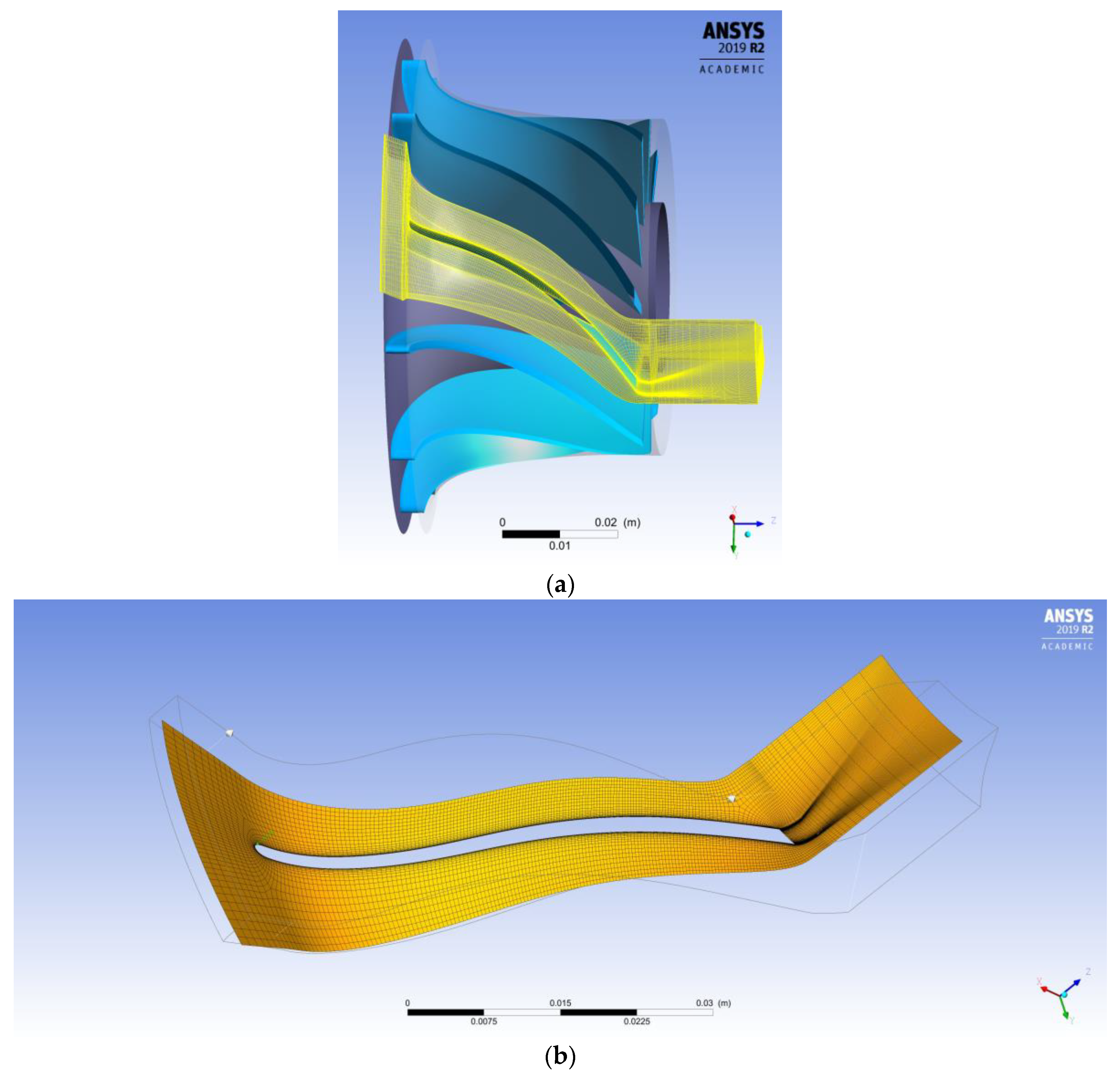
The preliminary HPT rotor geometry was designed by 1D methods described in the previous chapter, evaluating all the average thermodynamic and fluid-dynamic quantities at the mean-line for the rotor inlet and exit sections. Afterward, the preliminary 3D rotor shape was sized and meshed using ANSYS DesignModeler and Turbogrid standard features, and then numerically analyzed by means of 3D CFD simulations using ANSYS CFX [
38]. Thanks to the rotor symmetry, only two channels were taken into consideration. For the grid independency, simulations were carried out refining the structured mesh from 1.5 × 10
5 to 4 × 10
6 nodes per channel. In the end, a mesh of about 300,000 nodes per channel was set as the best compromise. In
Figure 4a,b details of the mesh blocks (inlet unvaned block, rotor and exit block) are depicted.
As reported in
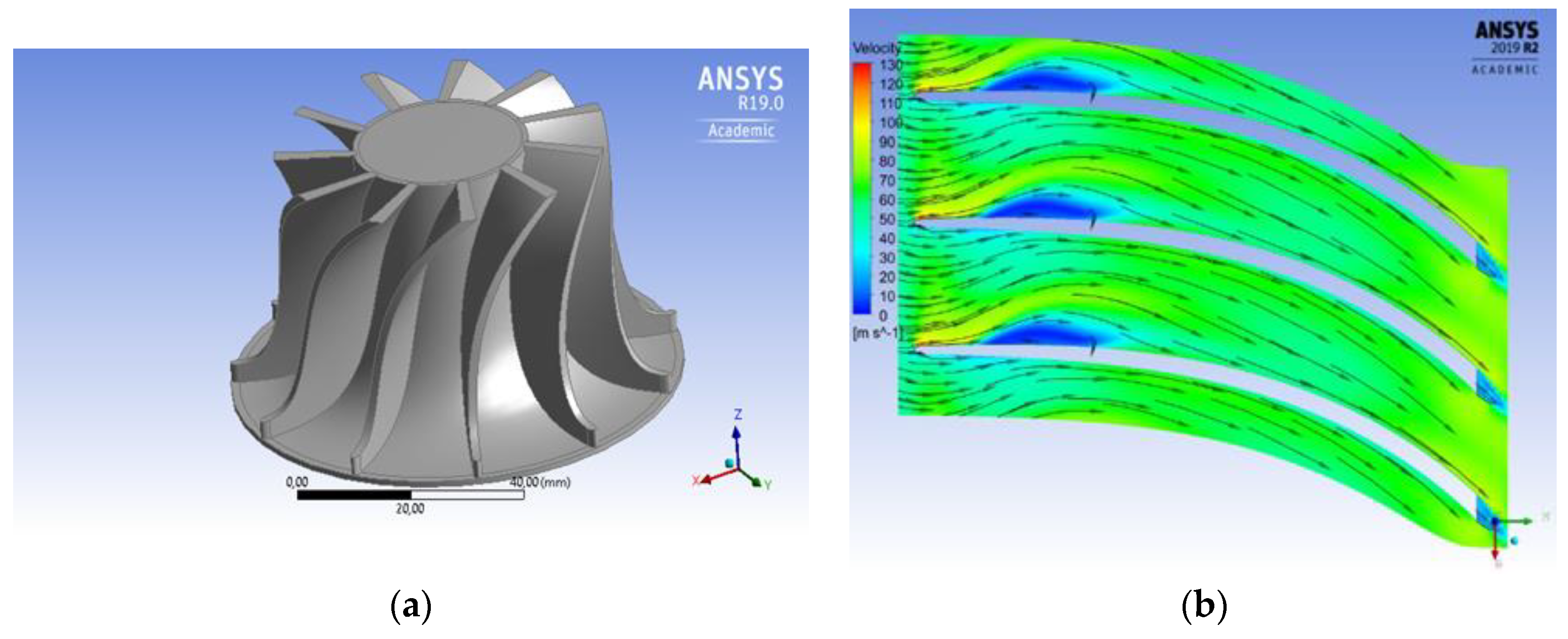
Figure 5a,b, achieved CFD analyses highlighted an inadequate fluid-dynamic behavior even at nominal conditions: a vast flow separation region can be observed on the suction side (the blue zone with flow separation in
Figure 5a due to an incorrect incidence flow angle at the inlet section (
Figure 5b). Such phenomena are due to the rough evaluation of the local flow density with 1D conventional models. To improve the rotor design, sensitivity analyses were carried out varying the following geometric parameters:
Hub and shroud profiles (axial rotor length as well as hub and shroud meridional shapes);
Number of rotor blades: from 10 to 16
Blades’ thickness and thickness distribution from leading to trailing edge
Blades’ height at rotor inlet section: from 3 to 5 mm
Absolute inlet angle (α2) from 65° to 69°
Blade angle variation along the path at the hub and tip lines (linear and several polynomial laws) to reduce stall effects in the rotor elbow
Such analyses led to an enhanced rotor geometry as reported in
Table 1 and shown in
Figure 6a. As depicted in
Figure 6b, the stall on the suction side was contained in a restricted area corresponding to the elbow. The internal rotor efficiency (at nominal conditions) increased from 68% (preliminary layout) to almost 90% (final layout). The rotor efficiency was evaluated as:
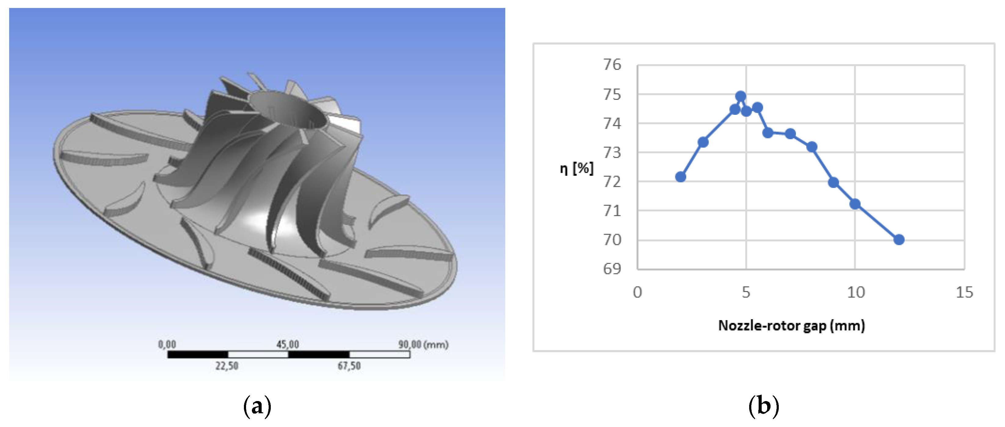
Thereafter, the vaned nozzle was assessed accordingly. Such a component needs to speed up the flow in the proper direction before entering the rotor. In this study, a nozzle equipped with fixed vanes was considered (without a variable stagger angle as in some industrial radial turbomachines) to lower component complexity and costs. In
Figure 7a, the overall HPT geometry (nozzles and rotor) is depicted. The designed rotor is shrouded to reduce volumetric losses; nonetheless, in
Figure 6a, it is shown unshrouded to highlight the shape of the rotor channels. The influence of the nozzle trailing edge wakes on the average stage performance was analyzed varying the gap between the nozzle exit section and the rotor inlet section. Two nozzle vanes and three rotor blades were considered. For each nozzle vane, a grid of about 190,000 nodes was set. As reported in
Figure 7b, a gap of 4.5 mm assures the maximum internal efficiency (about 75%) for the first stage. The efficiency was evaluated as total-to-static since stages are not assembled one after the other on the same shaft. Therefore, according to the diagram reported in
Figure 3c, the stage efficiency was evaluated as:
Performance drops at lower gaps are due to the flow distortion given by the nozzle trailing edge wakes. On the other hand, at higher gaps, despite the more uniform flow conditions at the rotor inlet, the efficiency decreases because the flow is no longer well guided by nozzle vanes.
4.2. Low-Pressure Turbine Design
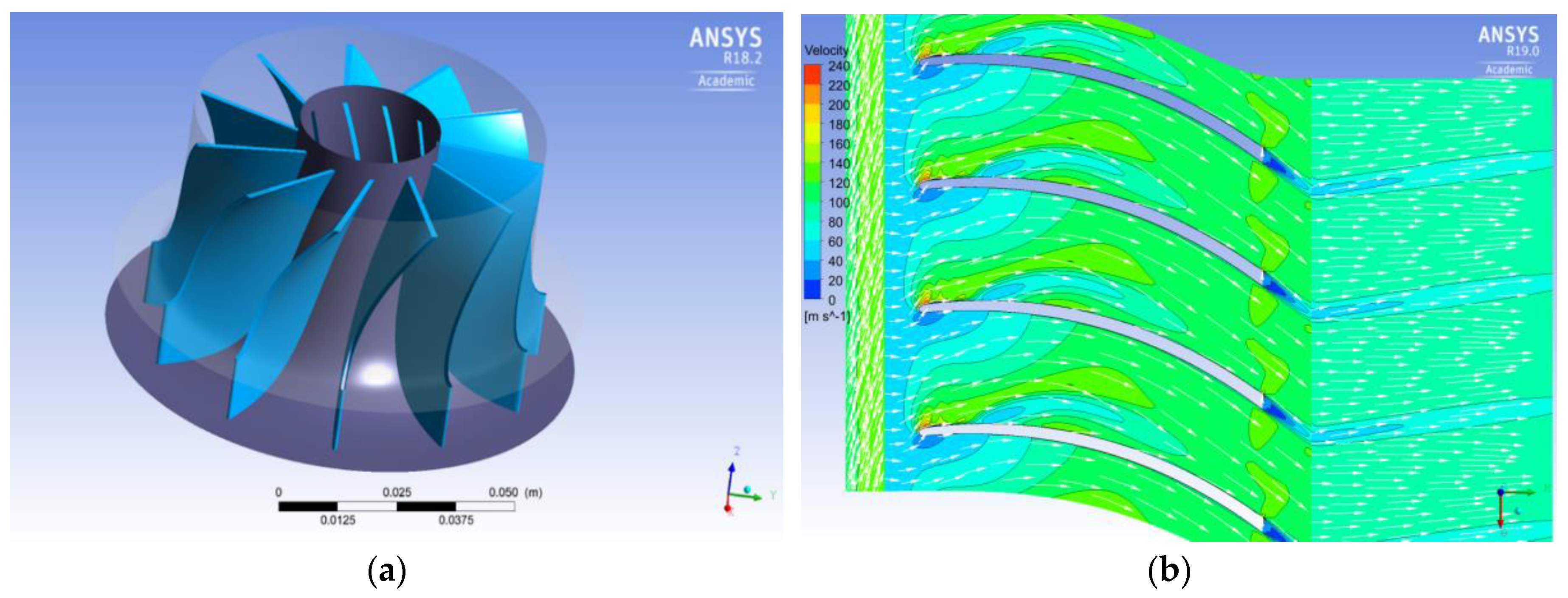
The LPT boundary conditions were fixed according to the HPT design results. In particular, 6.27 bar and 108 °C were imposed for nominal inlet total pressure and temperature, respectively. A total pressure of 2.2 bar was imposed at the exit section. On the basis of the 1D models described in the previous chapter, the nominal rotational speed was set at 27,000 rpm. While the HPT was equipped with nozzle blades to expand the WF partially before entering the rotor and, consequently, increase the inlet rotor blade height, in the LPT structure the nozzle row was omitted. The increase of the volumetric flow through the expansion and the need for good operational flexibility (LPT works in a wide range of inlet thermo-fluid dynamic conditions) lead to such a design choice. A shrouded rotor was taken into consideration to reduce volumetric losses.
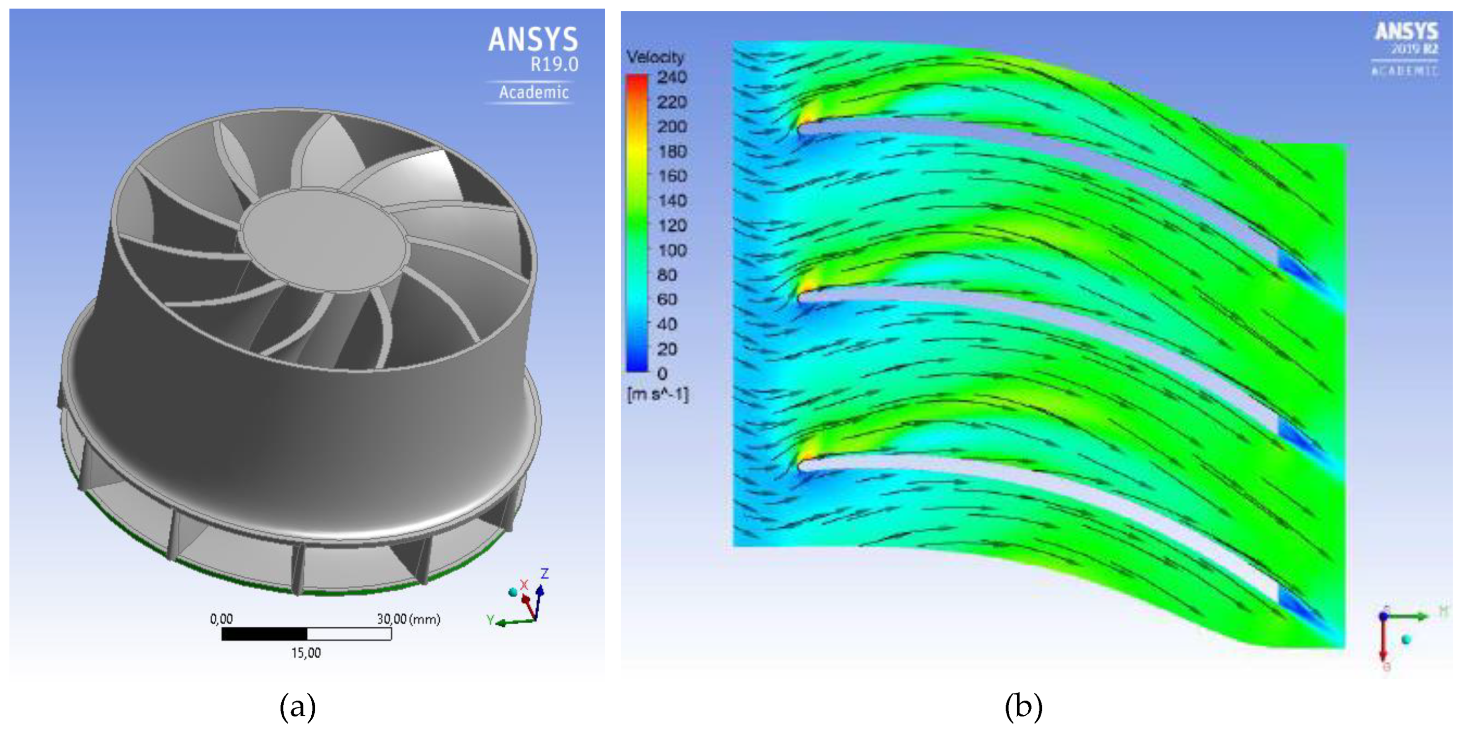
The preliminary 1D design results were taken as the starting point for a more detailed 3D design of the overall stage and, mainly, of the rotor. In
Figure 8a, the preliminary rotor layout is shown. A 3D quasi-steady-state CFD analysis was carried out. Two rotor channels were meshed according to models described previously. After a grid independency analysis (from 1.5 × 10
5 to 4 × 10
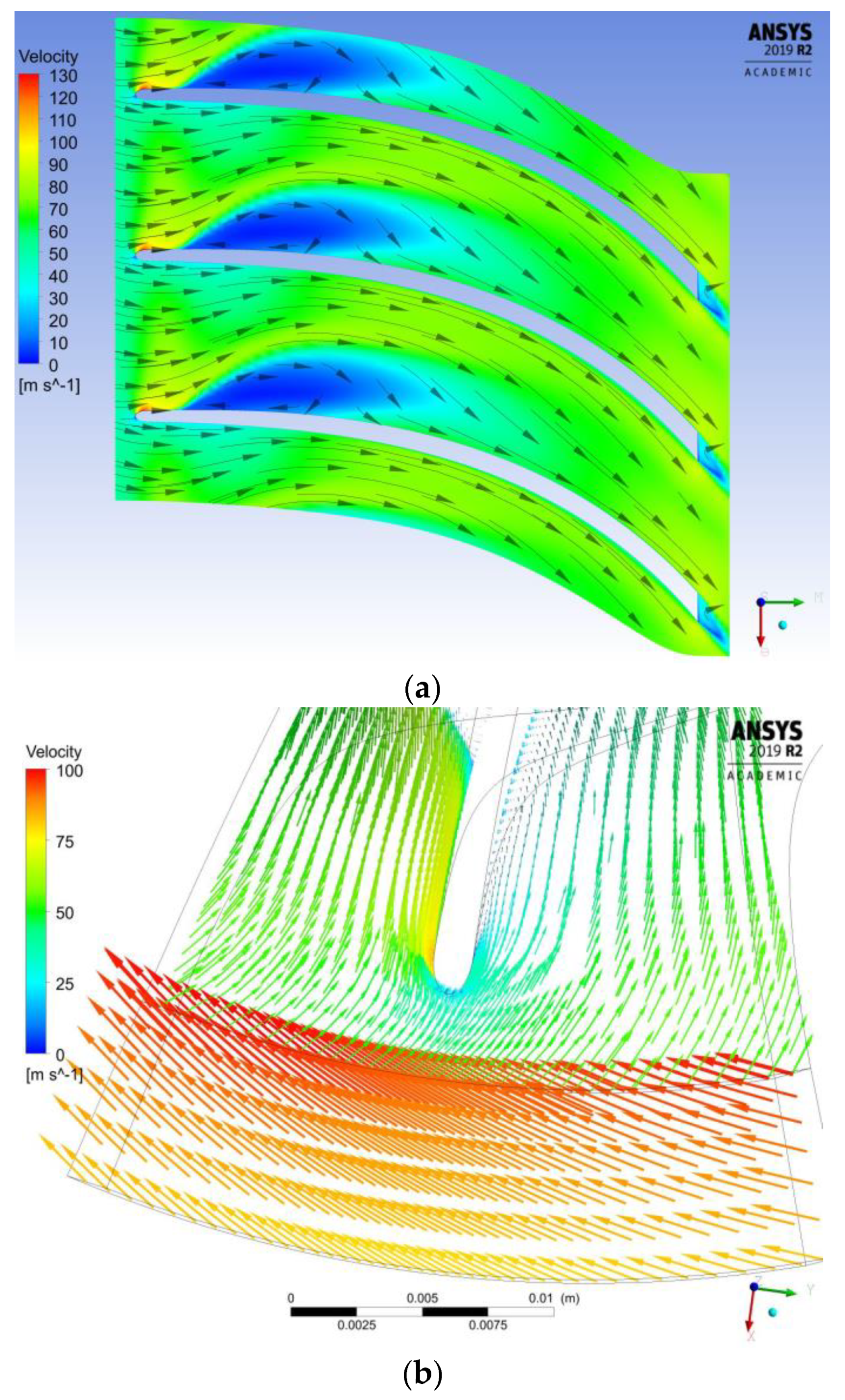
6 nodes per channel), a mesh of almost 420,000 nodes per channel was adopted. As in the HPT case, results were not acceptable: inlet volumetric flow rate and velocity direction were mostly different from what was evaluated using rough models. The incidence angle at the inlet section leads to a remarkable leading-edge stall on the pressure side, which affects all the fluid dynamic behavior in the flow path (
Figure 8b). Therefore, overall stage performance is dramatically reduced as highlighted by a stage efficiency (Equation (14)) of about 59%.
Sensitivity analyses were carried out, varying:
Shroud profile (shroud meridional shape)
Number of rotor blades: from 10 to 13
Blades’ thickness (from 1 to 2 mm) and thickness distribution from leading to trailing edge
Blades’ height at rotor inlet section: from 11 to 14 mm
Absolute inlet angle (α2) from 65° to 75°
Blade angle variation along the path at the hub and tip lines (linear and several polynomial laws) to reduce stall effects in the rotor elbow
In particular, the blade inlet angle was modified, and the inlet blade height was reduced as reported in
Table 2. Moreover, 3D rotor blade shape was changed varying the angle distribution along with the component. Finally, the enhanced geometry reported in
Figure 9a was developed. In
Figure 9b, it can be noted that the flow field is consistent in the new flow-path. The stall evidenced on the suction side is usually detected in radial inflow turbines because it is related to the 3-dimensional effects in the elbow. The CFD analysis of the new geometry at the nominal point led to a stage efficiency of 77% (Equation (14)).
5. Off-Design Analysis
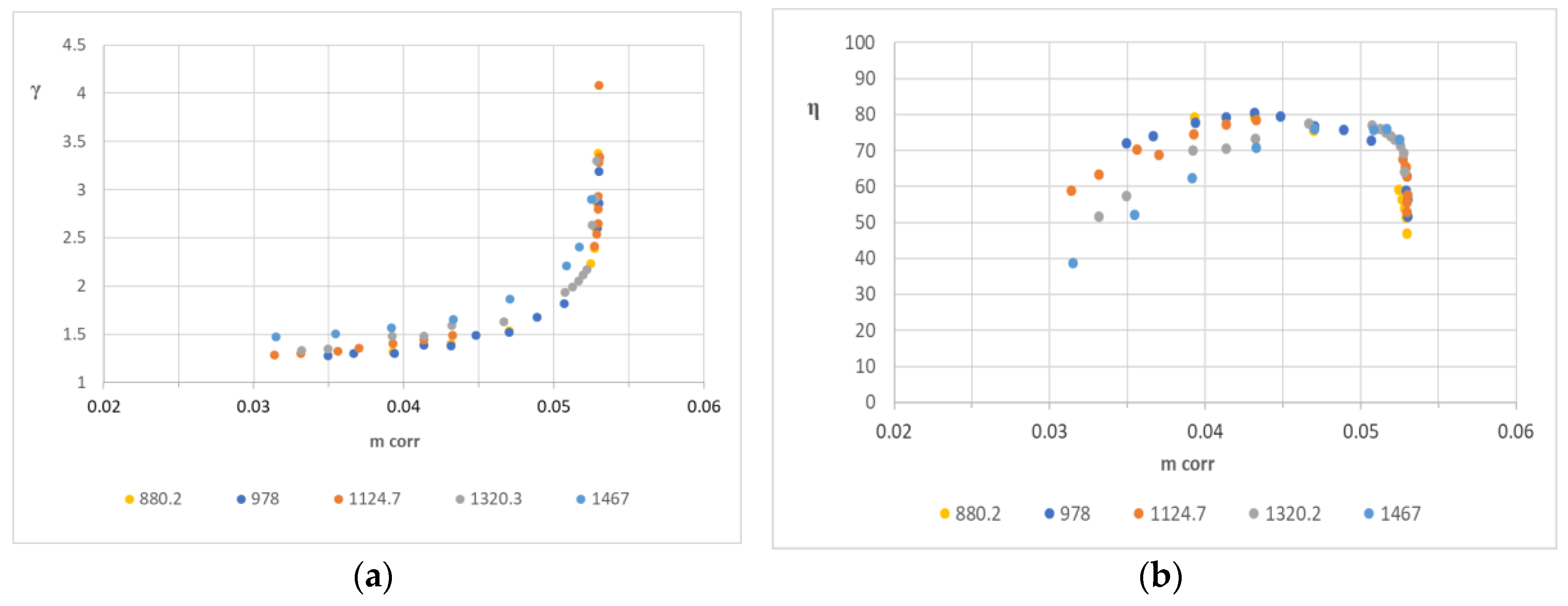
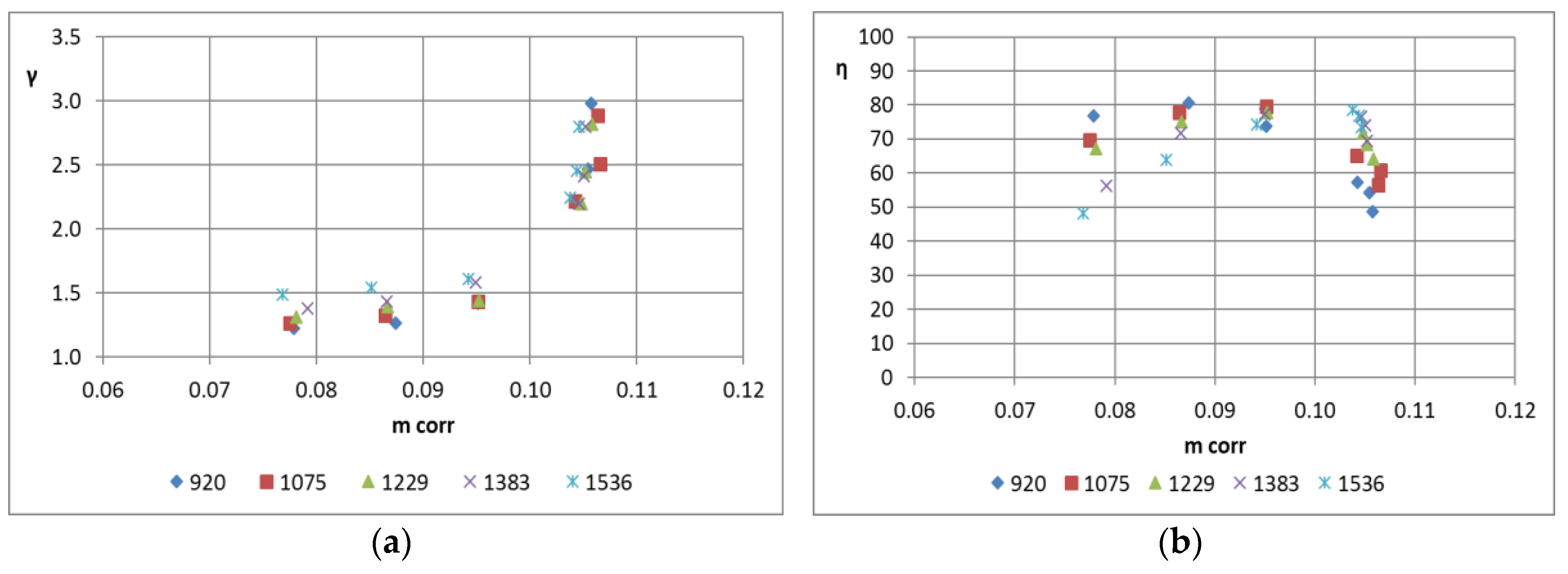
3-D CFD simulations have been performed at off-design for both HPT and LPT varying the rotational speed from 18,000 to 30,000 rpm. Achieved results are reported in
Figure 10 (HPT) and in
Figure 11 (LPT). Stage maps report pressure ratios (
Figure 10a and
Figure 11a) and isentropic efficiency (
Figure 10b and
Figure 11b) versus corrected mass flow rate defined as:
Performance curves are parametrized by the corrected rotational speed, given as:
being
T0 and
p0 stage inlet total temperature and pressure, respectively.
It can be noted that both stages work adequately in a wide range of mass flow rates and rotational speeds, reaching a stage total-to-static efficiency of almost 80% in both HPT and LPT. Chocked conditions occur for pressure ratio over 2.5 in both stages and, consequently, for such values, the stage performance drops down due to transonic effects (shock losses, unguided flow beyond shocks, wake losses).
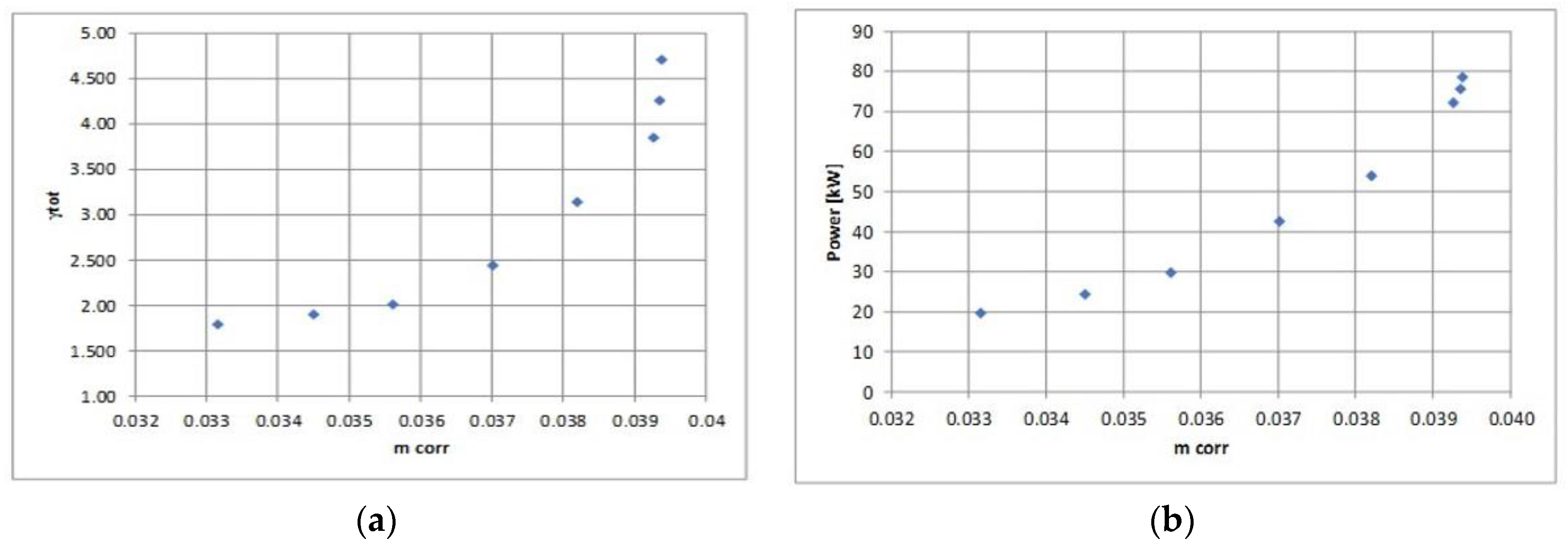
Once the HPT and the LPT were analyzed, a stage stacking was carried out to give the overall turbine performances. Due to the coupling with a synchronous electric generator, the stage will run at part load at a constant speed. Therefore, the HPT maintains its own nominal rotational speed (23,000 rpm) as well as the LPT (27,000 rpm). For each HPT corrected mass flow rate, the thermodynamic and fluid dynamic conditions detected at the HPT exit were averaged and provided, as boundary conditions, at the LPT inlet section. At off-design conditions, the outlet pressure was not fixed but evaluated as a dependent variable, while mass flow rate and inlet pressure and temperature were set as boundary conditions. Pressure drops in the piping which connects the stages were neglected, in the first instance. Results are reported in
Figure 12, where overall pressure ratio and power are given as a function of the corrected mass flow rate. The correction takes into consideration HPT inlet total pressure and temperature. It can be highlighted that the total pressure ratio is significantly lower than what was expected at the preliminary design stage to avoid the transonic conditions in the flow path. It reflects dramatically on the overall system performance because if the gap between evaporation and condensation pressure is maintained as fixed in the system analysis, the turbine will work in choked conditions reducing the component performance and, consequently, the plant efficiency. On the other hand, if the turbine is maintained subsonic, a higher condensation pressure (or a lower evaporation pressure) has to be set. It means a lower thermodynamic plant efficiency due to the reduction of the Carnot coefficient. Therefore, the determination of a trade-off between such aspects is crucial to optimize the power production of ORC plants.
6. Conclusions
In this study, a novel turbine for industrial small ORC plants was designed and analyzed at nominal and off-design conditions. The turbine is made of two radial-inflow stages, which increase the usual expansion ratio adopted for ORC plants. In this work, both stages were designed selecting the most proper main parameters on the basis of information given in the literature and included in the preliminary design procedure. Therefore, the stages have their own design rotational speed, and they are coupled with the generator in an integrally-geared layout.
Preliminary geometries were modified according to results achieved with 3-D CFD simulations performed on ANSYS-CFX. Such modifications were mainly connected with the mismatching detected between the expected rotor exit relative angle at the mean-line and the same angle found in the 3D CFD analysis. Indeed, the 1D correlation for the slip factor (developed for conventional fluids) does not seem to be reliable for the organic WF, and further investigations are necessary. Moreover, a relevant mismatching was found between average WF density at the rotor inlet section evaluated with 1D models and the density in the same section calculated by ANSYS CFX. Therefore, in the 3D analysis at nominal conditions, the WF incidence led to relevant stalls on the blades’ suction side, modifying completely the fluid-dynamic behavior into the channels in both stages. Thus, sensitivity analyses varying the most relevant geometric parameters were carried out to overcome such effects. The best configurations for HPT and LPT among those investigated were taken into consideration, and performance characteristics were examined for both stages. It was noted that, at the nominal point, overall stage performance evaluated by 1D models on the preliminary geometries are rather in agreement with performance calculated by CFD analysis on the enhanced geometries.
Thereafter, a simplified stage stacking was carried out to evaluate the overall performance at nominal and derated conditions. It was found that turbine power at the nominal point is 71.2 kWe. The nominal total expansion ratio (3.9) is considerably lower than what was expected during the preliminary design. Improvements in the off-design turbine’s flexibility are expected to be obtained using stages with variable speed. Moreover, further work is required to take into consideration pressure drops in the connection piping between the stages.


