Abstract
The integration of multiple energy sectors, such as electricity, heating, and mobility, into an overall smart energy system is a key part of the journey towards a fossil-free energy system. Exploiting the operational flexibility of these sectors will lead to the efficient operation of the integrated smart energy system. The use of heat pumps for the heating supply based on renewable energy resources is reasonable in many cases. Combining heat pumps with thermal storages, these systems can offer flexibility to an energy system based on fluctuating power generation. Flexibility can be defined as the capability to adapt an initial schedule in order to support the energy system in terms of the provision of power reserve. In this paper, an approach to determine the time-dependent flexibility potential of a heat pump system is presented. The optimization-based approach considers all the constraints resulting from the system topology, including the required heating demand of the connected building. As a result, constraints for the integration of the available flexibility in a modified Optimal Power Flow (OPF) calculation are given. These lead to the ensured feasibility of the flexibility provision without considering the system boundaries of the heat pump site within the OPF.
1. Introduction
In Germany, the majority of renewable energy generation is connected to the distribution grid, with the highest share of renewable generation sites in low voltage grids [1]. Hence, high power generation occurs in the low voltage grid, leading to inversions of the power flow from low to medium voltage grids if the power consumption is low in times of high generation. In the same time, the coupling of the heat, mobility, and electricity sectors leads to an increasing power consumption in distribution grids because of growing numbers of electric vehicles or electric heaters [2,3]. These developments might lead to operation situations exceeding the capacity of the grid. Consequences of this might be line overloads or voltages out of specified voltage ranges, with the latter occurring more frequently [1]. To guarantee an operation within the specified limitations, a conventional approach is the extension of the grid. A competing approach to grid extension measures is the consideration of system flexibility.
In [4], literature about energy system flexibilities is reviewed, concluding that there is a high interest in this topic. Amongst others, storage options, demand side management, and flexibility in generation as types of system flexibility are discussed [4].
Considering the distribution grid, especially demand side management as well as generation curtailment are of importance. The authors of [4] highlight the flexibility potential of thermal energy storages in residential heating systems.
The authors of [5] give an overview of investigations tackling the potential of residential power-to-heat as a technology to support the integration of renewable energies. Model formulations for heat pumps and thermal storages as well as an overview of actual research questions and findings, e.g., the integration of renewable energy generation or reducing CO2 emissions, are presented. Following the conclusion of the authors of [5], for the integration of renewable energy generation technologies, heat pumps may play a major role of the residential power-to-heat options.
The authors of [6] report on an increasing role of heat pumps in the heating sector based on data about sold heat pumps in Europe in 2010–2015. Furthermore, the results of the analysis of pathways for transforming the German energy system [7] indicate that heat pumps are the dominating heat supply technology for buildings in 2050. The technology of heat pumps is an open field of research. The authors of [8] present the research activities of recent years, focusing on better coefficients of performance (COP) in heat pump systems based on vapor compression through, e.g., multistage cycles or improving compressor performance.
The consideration of heat pump system flexibility to support the grid through the adjustment of the power consumption schedule is tackled in different ways. One approach in making use of the flexibility regarding the time of electricity consumption of heat pumps combined with a thermal storage is to implement a schedule optimization. In [9,10,11], the flexibility potential of heat pumps is investigated by comparing different optimization strategies of the heat pump operation schedule and a temperature controlled schedule. Another possibility is the integration of the flexibility option as a power generator in an optimal power flow (OPF) calculation, as it is done for battery storages in [12,13]. Both options presume that the power consumption scheduling is done with respect to optimal grid operation states and internal system boundaries only.
As these operation strategies might collide with the interests of the owner in a cost-optimized operation strategy, [14] investigates a multi-use approach, in which a cost optimization takes place, while the flexibility option is still operating in a grid supporting manner. Therefore, the approach of [15] is implemented, in which a modified OPF setting calculates capacity corridors, which limit the power consumption for each grid connection point. Subsequently, an optimization of the power consumption schedule within this corridor, e.g., a cost optimization, is executed for each connection point.
In [16], the flexibility of different energy hubs is also integrated in a modified OPF calculation, but the sequence is the other way round. First, an optimization for each grid connection point is done. Then, the power consumption at grid connection points, where flexibility is available, is changeable within the OPF calculation. In the OPF itself, no information about the system boundaries of grid-connected systems is available. This leads to an iterative approach, as a second schedule optimization follows the OPF calculation, which maximizes the provision of the demanded flexibility considering the system boundaries of the individual energy hub.
Avoiding additional iterations requires an adequate constraining of the flexibility use to the available flexibility at an individual energy hub. In this paper, these constraints are formulated for the flexibility provided by an individual household with a heat pump and photovoltaic (PV) system on the rooftop.
Starting with the model of a household with heat pump system, which provides the flexibility, the time-dependent availability of flexibility is investigated. Constraints for the modified OPF are formulated in such a way that, in the OPF, no state equations or system boundaries of the heat pump system are applied. The remainder of this paper concludes with the application of the found constraints in the modified OPF calculation. Therefore, a case study with a 12-bus low voltage distribution grid is set up, into which the household with a heat pump system is connected.
2. Methods
2.1. Model of an Exemplary Heat Pump
The aim of this work is to define the flexibility offered by a heat pump while in operation. Therefore, a heat pump model, indicating the specific characteristics, is set up. To investigate the flexible power of a heat pump system, the critical parameters are the electric power consumption as well as the COP, which describes the relation between thermal power output and electrical power consumption. The parameters of one exemplary heat pump are approximated in order to be able to quantify the flexibility offered by this particular heat pump dependent on its scheduled power consumption.
Considering an on/off controlled heat pump, the electrical power consumption of the compressor depends on the mass flow as well as the difference in enthalpy of the fluid before and after compression, which is proportional to the temperature difference presuming a constant heat capacity cp of the refrigerant. A throttle within the thermodynamic cycle of heat pumps controls the mass flow, guaranteeing superheating in the evaporator [17]. The dependency of the power consumption of the exemplary heat pump “WPL 34” [18] (p. 5) on the sink temperature as well as the temperature difference between ambient and sink temperature is linearly approximated (Equation (1)).
The temperature dependency of the COP of the heat pump is implemented in Equation (2), following the linear modelling in [11] based on the idea of modelling the COP depending on the temperature difference between source and sink temperature [19]. Again, the data of the exemplary heat pump “WPL 34” [18] (p. 5) is approximated. The absolute value is adjusted to model a heat pump with a thermal energy generation that is at minimum 3.5 times higher than the electrical energy input in one year. This is done since in Germany incentives promote air/water heat pumps with this specification [20].
Considering the heat pump as the sole heat generator of a private household, the flexibility is provided through combination with a thermal storage, which is supposed to be perfectly mixed and contain 800 liters of water. Simplified, the storage temperature is supposed to equal the sink temperature . With the difference between this temperature and the minimum allowed one of the storage, which is set to 45 °C in this model, the calculation of thermal energy in the storage in kWh with the mass and specific heat capacity of water is possible (3). The maximum possible temperature of the storage and sink is set to 66.5 °C, resulting in a maximum possible thermal energy in the storage of approximately 20 kWh.
With these Equations (1)–(3), a steady state simulation model of a heat pump system with discrete time steps is set up. Assuming a storage without thermal losses and installed in parallel with the heat pump and heating system of the household, the thermal energy in the storage before the time step t and the in and out flowing thermal energy while add up to the thermal energy after the time step. This leads to the following Equation (4), with representing the thermal power demand in time step :
To simulate the operation schedule of a heat pump within a household, an optimization problem is set up. The simulated system includes a household with the heat pump as a sole heat generator, combined with storage to offer flexibility. Furthermore, the household has a photovoltaic (PV) site on the rooftop. The aim of the heat pump scheduling is to maximize the self-consumption of the electricity generated by the PV system to reduce the electricity costs. Considering losses that might occur with start-ups, a cost optimization would also result in promoting full cycles of thermal storage.
This behavior of the heat pump is approximated by the objective function (5), containing a penalty factor for switching and promoting run times while electricity is generated with the PV system. Avoiding a mixed integer optimization, the model allows continuous states of the heat pump power but privileges the maximum power state. Hence, the optimal solution contains some forbidden states, which are manually set to an allowed state afterwards.
To provide an exemplary schedule of the heat pump, the optimization runs for the simulation horizon T of 24 h, considering the heat demand and PV production as perfectly predicted values. As the second term in the objective function promotes power consumption between the on and off states, whereas the first term privileges maximum power consumption, they need to be differently rated. To reach adequate schedules with mostly full cycles of the thermal storage and still promoting self-consumption four sequenced optimizations of the same time horizon are executed. The parameters are , , , and reducing by one in each optimization run being in the four runs. The result of one optimization forms the starting vector of the following one with changed .
Additional constraints (6) and (7) represent the upper and lower bounds of power consumption and storage capacity. represents the maximum storage capacity of 20 kWh in all time steps besides the last one. is set to 10 kWh to avoid maximum energy in the storage at the end of the optimization horizon, which is promoted by the objective function. As the variable describes the energy in the storage at the beginning of time step , constraints (8) and (9) are implemented to guarantee an allowed state of storage after the last time step in the considered simulation horizon. Constraint (10) further specifies the charging state of the storage in the initial considered time step. is set to zero on the first simulated day and adopts the charging state after the last simulation step of the previous day, if more than one day is simulated.
2.2. Implementation of the Heat Pump Flexibility
The authors of [21] define flexibility as the changing of electrical power consumption or generation as a reaction to an external signal, providing ancillary services. Following this definition, available, flexible power per time step represents the possibility of a heat pump to change the electrical power consumption compared to the initial schedule.
Based on the two-step optimization of [16], the required flexibility in the operation time of a heat pump is calculated. In this two-step approach, a cost optimization of individual energy hubs, e.g., the household with a heat pump in this example, is the first optimization step. In the second step, the required flexibility in active power consumption is calculated with the scheduled power consumption as input. As in this calculation no information about the availability of flexible power is included, another re-optimization of the individual energy hubs is needed, trying to adapt the new schedules with the required flexibility [16].
The contribution of this work is to characterize the time-dependent availability of flexibility depending on the scheduled power consumption, aiming a two-step optimization based on the one in [16] but without the need of energy hub re-optimization. The flow chart of this two-step optimization is shown in Figure 1.
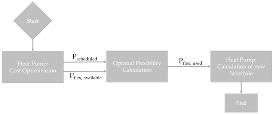
Figure 1.
Flow diagram of the Optimal Flexibility Calculation framework.
The objective of the included optimal flexibility calculation is to minimize flexibility use while guaranteeing a grid state within the limitations (e.g., voltage limitations). Therefore, a grid-connected heat pump, as an exemplary flexibility option, communicates its power consumption schedule and its possibilities to change this schedule .
To keep the calculation of the optimal flexibility use as simple as possible, should suffice as input for a calculation of flexible power use. Thus, neither physical system equations nor states of the heat pump system are integrated in this calculation. Accordingly, the calculation of the resulting schedule of the heat pump, with the required flexibility as input and under consideration of the physical states as well as the boundaries of the system is the next step in Figure 1.
3. Results
Limiting factors for load shifting potential of heat pumps are heat demand, the size of the heat pump, and storage, as well as the dynamic properties of the system [6]. In addition, the load shifting potential depends on different states of the system, as described in [11].
The first step of the characterization of time-dependent availability of flexibility is a definition of limiting factors and a characterization of interdependencies between different time steps. Secondly, the available, flexible power of a heat pump system is integrated in a modified OPF calculation, in which the state of the heat pump as well as the heat pump model are not considered.
3.1. Available, Flexible Power of the Heat Pump System
Figure 2 shows the scheduled power consumption resulting from the optimization problem of the heat pump model for one day. Based on this and considering only the power restrictions of an ON/OFF controlled heat pump, the available, flexible power in positive and negative direction depends only on the actual state of the heat pump. If the heat pump is on in a specific time step, only negative, flexible power of the amount of actual power consumption is available, as only switching off is possible. The same is valid if the heat pump is off, as only switching on is possible (see Figure 2 thin lines).
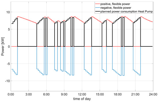
Figure 2.
Positive and negative flexible power according to the scheduled power consumption per time step.
The heat pump is defined as the sole heat generator of the household, and resident’s comfort should not be affected by the flexibility supply. Therefore, a consideration of the thermal energy in the storage in addition to the power restriction is obligatory. The thermal energy in the storage effects the available, flexible power in two ways. Firstly, negative, flexible power is only available if switching off is possible and the storage can cover the thermal demand of the time step. Positive, flexible power is available if switching on is possible and does not lead to an exceeding of the maximum storage capacity. Secondly, the thermal energy in the storage is a linkage between time steps, since power generation in one time step affects the thermal energy in the storage for the following time steps.
As the heat pump is the sole heat generator, power consumption can be shifted in time but is not replaceable. Therefore, a use of flexibility in one time step results in changing availabilities for flexibility in the following time steps. Figure 3 illustrates this.
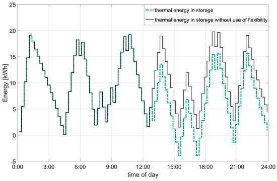
Figure 3.
Thermal energy in the storage with (dashed line) and without the use of flexible power.
Figure 3 shows a comparison of two possible courses of thermal energy in the storage in one day. The continuous line shows the scheduled energy in the storage, while the dashed one shows the resulting energy after the use of flexibility at 12:30. The use of flexibility without further changes in the heat pump schedule leads to negative values of thermal energy in the storage at 15:00, implying that the thermal demand cannot be covered anymore. Since this is a forbidden state, the use of flexibility at 12:30 results in the need for another change in the heat pump schedule before the storage reaches negative values.
Equation (1) points out the dependency between the electrical power consumption of the heat pump and the temperatures of heat source and sink. As the temperature of the heat sink is varying with changing thermal energy in the storage, the use of flexibility in one time step (see the filled area in Figure 4) induces a changing power consumption of the heat pump in the following time steps (Figure 4).
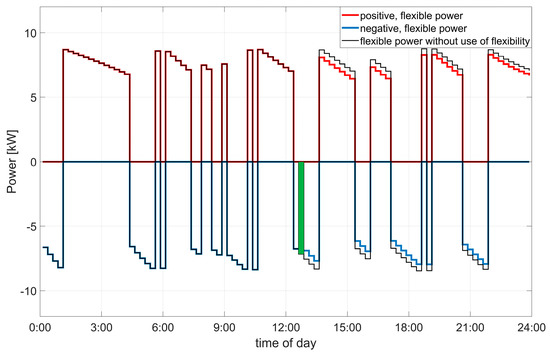
Figure 4.
Available, flexible power without using flexibility at 12:30 (thin line) compared to the one after using flexibility.
In addition, considering the heat pump power Equation (1) and the storage Equation (3), the thermal energy generation also varies with different temperatures and electrical power consumptions. This indicates a dependency between the electrical power consumption, the thermal energy generation and the operating point of the heat pump.
In summary, the previous investigations describe the available, flexible power of a heat pump according to the planned power consumption, the energy in the storage and the operating point of the heat pump. Table 1 represents the limitations of the time-dependent flexibility of a heat pump and the parameters they depend on.

Table 1.
Summary of limitations of the time-dependent flexibility of heat pumps.
3.2. Formulation of Constraints for the Modified Optimal Power Flow Calculation
The above-mentioned flexibility limitations and their dependencies need to be expressed state independent for the integration in the modified OPF calculation.
As sown in Figure 5, this is done with additional inequality constraints. The power limitation is dependent on the scheduled power consumption, which is a fixed input parameter for the modified OPF. Therefore, this limitation is a static constraint of the following structure (11).
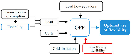
Figure 5.
Modified Optimal Power Flow (OPF) calculation with input and output as well as constraints.
For an ON/OFF controlled heat pump, the switching operation is the only possibility to change the power consumption. Thus, an integer variable indicates the use of flexibility. Multiplication with the available power of the time step yields to the flexible power of the time step (12).
The energy limitation, however, forms a dynamic constraint, as this limitation is a linkage of the use of flexibility of different time steps. Hence, the energy constraint has to consider the required flexibility of all time steps until the current one. Comparable to [12], this dynamic constraint is implemented by a summation of flexibility in all time steps. For each time step , there are two additional inequality constraints: one for the lower and one for the upper energy limitation (13), (14). describes the thermal energy generation within a specific time step.
As stated above, the actual power consumption and thermal energy generation is dependent on the state as well as the state history. Regardless of the fact that the actual state of the heat pump is not part of the modified OPF calculation, the availability of the requested flexibility from the heat pump system must be ensured. To this end, an adaptation of the power and energy constraints (12)–(14) is necessary, as the time-dependent flexibility depends on the state and state history (see Table 1).
Therefore, is set to the minimum available, flexible power , if it is positive in time step t (15). With a given ambient temperature , the minimum flexible power is a minimization of Equation (1) with respect to the storage temperature .
This ensures the availability of the flexible power. In addition, the real power consumption of the heat pump, considering the actual state of the system, forms a valid solution to the modified OPF problem. In case of the use of negative, flexible power, is set to the scheduled power consumption , as switching off means a reduction of planned power consumption by this amount of power.
The procedure for the energy constraints is similar as the minimum (16) and maximum (17) thermal energy generation per time step are used to calculate the change of thermal energy in the storage by the use of flexibility. The minimum and maximum thermal energy generation are the extreme values of the quadratic equation of , using Equations (1) and (2) and presuming that the ambient temperature is known.
Summing up, Table 2 represents the used additional constraints for the implementation of the available, flexible power of a heat pump system in the modified OPF calculation.

Table 2.
Additional constraints added to the modified OPF calculation to constrain the use of flexibility to the available flexibility.
4. Case Study
The method for the optimal calculation is based on the contributions in [8]. The aim of this approach is to calculate the cheapest combination of several flexibility options to enable a grid operation compliant to relevant standards, such as EN 50160, which defines the voltage characteristics of electricity supplied by public networks. In this contribution, a linearized power flow calculation method is used to reduce the required computation time of the modified OPF approach. This approach is based on the Implicit Linearization of the Power Flow Manifold developed by the authors of [22]. The state variables describing the power network are voltage magnitudes , voltage angles and active and reactive loads at the buses. Injections, such as photovoltaic systems are modelled as negative loads. All buses, except the slack bus, are modelled as PQ-buses.
Using these state variables, the linear model given in (19) can be formulated. In this case the flat voltage solution is chosen as linearization point . The matrix contains the linearized power flow equations that describe the load flow between the buses. In , the derivatives of the bus models (PQ-buses and slack bus) are given. As the shunt admittances are set to zero, contains the load profile values of the buses.
To include the flexibility of controllable units such as heat pumps in the calculation, the load at bus i is decomposed. The load at bus i is the sum of the initially scheduled load resulting from the cost optimization and the flexible load .
The objective function of the modified OPF approach is to minimize the required flexibility. This results in a quadratic objective function (21). This function is the sum of the squared flexible loads weighted by an individual cost term . The state variable can be calculated according to (12).
The flexible load variables and also need to be included in the linear power flow constraints. First, the additional state variables need to be included in the state vector. Since the flat start solution is chosen as linearization point, is a zero vector (23).
The consideration of the flexible load variables in the power flow equations leads to the linear equality constraints given in (24). With being added to the state vector, the matrix on the left hand side needs to be modified. With the addition of the matrix the active and reactive flexible power is added to the bus models. The matrix extends the PQ-bus models. All entries are zero except for the entries at the positions of the state variables included in .
In addition to this system of linear equality constraints and the limitation of the available flexibility, the following bounds (25) and (26) are included as further constraints. The limitation of the available flexibility is described in the previous sections.
The first bound limits the voltage magnitude values to the values in accordance to the relevant standard. In the following simulations, this range is set to +/−5%. The second bound limits the power flows to the technically feasible values to avoid line overloading.
For an investigation of whether the deduced constraints limit the availability of the flexibility in the way that the heat pump system of the household could realize the resulting schedule, the test grid from [16] is set up. This grid consists of one low voltage feeder with 0.4 kV nominal voltage and 12 buses. Bus 1 represents the slack bus, at which the exchange power with the overlaying medium voltage grid is calculated. Figure 6 shows the grid of the case study.

Figure 6.
Test Case: 12-bus low voltage grid.
The household with a heat pump is connected to bus six of the low voltage feeder, and, at bus ten, there is a PV site with 25 kWpeak. The input data for the modified OPF calculation, as described in the previous section, are the planned power consumption or feed in for a specified time horizon at each grid connection point. These are exemplary time series for households developed with [23] and PV power generation, as well as the simulated time series for the household with PV site and the heat pump at bus six. The optimization variables in this OPF calculation are the flexible active power consumption at buses six and ten, as these two buses are the only ones providing flexibility. For bus ten, the provision of flexibility means the curtailment of the power generation at the PV site, whereas at bus six flexibility is provided through a change of the heat pump schedule. Aiming to integrate as much renewable power generation as possible, the flexibility provision with the heat pump is preferred through lower costs.
The top of Figure 7 shows that the state of the ON/OFF controlled heat pump is the same in all time steps in the feasible schedule realized by the heat pump and the schedule calculated by the modified OPF method. In time steps, in which the heat pump is switched on to provide flexibility, the OPF considers the minimum possible power consumption for this time step. Therefore, the scheduled power consumption calculated with the OPF is lower than in the realized schedule (e.g., at 12:00 or 12:30 in Figure 7, top and middle).
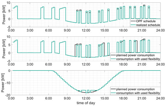
Figure 7.
Top: a comparison of the resulting schedule from the OPF calculation and the related feasible schedule calculated with the method described in Section 2; middle: a comparison of the modified OPF input time series of power consumption and consumption with the use of flexibility for bus six; bottom: the same as in the middle for bus ten.
Figure 8 shows that without the use of flexibility, the voltage exceeds the required voltage range at bus ten between 11:15 and 13:00. In two time steps within this period (at 12:00 and 12:30), it is possible to use the flexibility of the heat pump to prohibit the curtailment of the power generation by the PV site at bus ten (Figure 7 middle and bottom). All the other switching procedures, activated through the modified OPF calculation (Figure 7, middle), aim to fulfill the energy constraints, introduced in Section 3.2 to guarantee a feasible solution with the heat pump being switched on and off, as defined by the OPF calculation.
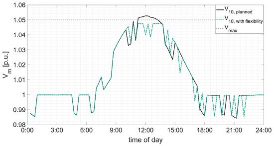
Figure 8.
Comparison of voltage time series at bus ten with planned power consumption at all buses and with usage of flexibility at bus six and ten (dashed line).
The changing states of the heat pump in former time steps lead to different temperatures in the storage. Therefore, even in time steps without changing states of the heat pump, the power consumption differs from the initial schedule (e.g., Figure 7 (top) at 14:00, 17:30 as well as at 21:15).
However, Figure 8 shows that, in this case, the use of flexibility leads to a voltage within the required range in all considered time steps. The heat pump system connected to bus six can deliver the requested flexible power and adjusts the schedule. With the implementation of the described constraints, it is possible to consider only available flexible power in the modified OPF calculation. The calculated on and off states of the heat pump are therefore feasible considering the constraints at the household site. Minor differences in power consumption occur because of differing temperatures in the storage.
5. Discussion
The investigation of the available flexibility deduced from an optimal schedule of a heat pump leads to abstract constraints for the implementation in a modified OPF calculation. With these constraints, it is possible to consider only the available, flexible power of the heat pump system in the modified OPF calculation. Knowledge about the actual state of the flexibility providing system is not required in the modified OPF calculation as the abstract inequality constraints ensure that the calculated use of flexibility can be provided.
Further investigations need to characterize the impact of changing power consumption because of the different storage temperatures in changed schedules. In addition, this investigation considers only perfect foresight. The handling of uncertainties in power consumption planning and the prediction of PV power generation is left for future work.
Author Contributions
Conceptualization, M.Z., S.S., F.M. and L.H.; methodology, S.S. and M.Z.; software, S.S. and M.Z.; validation, S.S., M.Z., F.M. and L.H.; investigation, S.S. and M.Z.; writing—original draft preparation, S.S. and M.Z.; writing—review and editing, F.M., L.H., M.R.S., T.L.; supervision, M.R.S., T.L. All authors have read and agreed to the published version of the manuscript.
Funding
This research received no external funding.
Conflicts of Interest
The authors declare no conflict of interest.
References
- Büchner, J.; Katzfey, J.; Flörcken, O.; Moser, A.; Schuster, H.; Dierkes, S.; van Leeuwen, T.; Verheggen, L.; Uslar, M.; Amelsvoort, M. Moderne Verteilernetze für Deutschland (Verteilernetzstudie). Abschlussbericht, Studie im Auftrag des Bundesministeriums für Wirtschaft und Energie (BMWi); E-Bridge: Berlin, Germany, 2014. [Google Scholar]
- Schuster, H. Zukünftige Rolle des Verteilnetzbetreibers in der Energiewende; E-Bridge: Berlin, Germany, 2017; Available online: https://www.bdew.de/energie/studie-rolle-verteilnetzbetreiber-energiewende/ (accessed on 9 February 2020).
- Quaschning, V. Sektorkopplung durch die Energiewende. Anforderungen an den Ausbau Erneuerbarer Energien zum Erreichen der Pariser Klimaschutzziele unter Berücksichtigung der Sektorenkopplung; Hochschule für Technik und Wirtschaft HTW Berlin: Berlin, Germany, 2016. [Google Scholar]
- Lund, P.D.; Lindgren, J.; Mikkola, J.; Salpakari, J. Review of energy system flexibility measures to enable high levels of variable renewable electricity. Renew. Sustain. Energy Rev. 2015, 45, 785–807. [Google Scholar] [CrossRef]
- Bloess, A.; Schill, W.-P.; Zerrahn, A. Power-to-heat for renewable energy integration: A review of technologies, modeling approaches, and flexibility potentials. Appl. Energy 2018, 212, 1611–1626. [Google Scholar] [CrossRef]
- Fischer, D.; Madani, H. On heat pumps in smart grids: A review. Renew. Sustain. Energy Rev. 2017, 70, 342–357. [Google Scholar] [CrossRef]
- Henning, H.-M.; Palzer, A. What will the Energy Transformation cost? Pathways for Transforming the German Energy System by 2050; Fraunhofer ISE: Freiburg, Germany, 2015; Available online: https://www.ise.fraunhofer.de/content/dam/ise/de/documents/news/study-what-will-the-energy-transformation-cost.pdf (accessed on 9 February 2020).
- Chua, K.J.; Chou, S.K.; Yang, W.M. Advances in heat pump systems: A review. Appl. Energy 2010, 87, 3611–3624. [Google Scholar] [CrossRef]
- Miara, M.; Günther, D.; Leitner, Z.L.; Wapler, J. Simulation of an Air-to-Water Heat Pump System to Evaluate the Impact of Demand-Side-Management Measures on Efficiency and Load-Shifting Potential. Energy Technol. 2014, 2, 90–99. [Google Scholar] [CrossRef]
- Spitalny, L.; Diekerhof, M.; Myrzik, J.M.A. Potential und Effizienzbetrachtung beim Lastmanagement von Wärmepumpen im Sektor der privaten Haushalte. In Tagungsband/Konferenz für Nachhaltige Energieversorgung und Integration von Speichern (NEIS 2013), Hamburg, Germany, 12–13 September 2013; Schulz, D., Ed.; Helmut-Schmidt-Universität: Hamburg, Germany, 2013; pp. 25–32. ISBN 9783868180435. [Google Scholar]
- Fischer, D.; Lindberg, K.B.; Mueller, S.; Wiemken, E.; Wille-Haussmann, B. Potential for Balancing Wind and Solar Power Using Heat Pump Heating and Cooling Systems. In Solar Integration Workshop, Proceedings of the 4th International Workshop on Integration of Solar Power into Power Systems, Berlin, Germany, 10–11 November 2014; Betancourt, U., Ackermann, T., Eds.; Energynautics: Darmstadt, Germany, 2014; ISBN 3981654900. [Google Scholar]
- Gill, S.; Kockar, I.; Ault, G.W. Dynamic Optimal Power Flow for Active Distribution Networks. IEEE Trans. Power Syst. 2014, 29, 121–131. [Google Scholar] [CrossRef]
- Gabash, A.; Li, P. Active-Reactive Optimal Power Flow in Distribution Networks with Embedded Generation and Battery Storage. IEEE Trans. Power Syst. 2012, 27, 2026–2035. [Google Scholar] [CrossRef]
- Deutsche Energie-Agentur GmbH (Ed.) dena-Netzflexstudie. Optimierter Einsatz von Speichern für Netz- und Marktanwendungen in der Stromversorgung; Deutsche Energie-Agentur GmbH: Berlin, Germany, 2017. [Google Scholar]
- Kornrumpf, T. Neue Energie aus Wuppertal/Bewertung von Flexibilitätsoptionen in Mittelspannungsnetzen, 1st ed.; epubli: Berlin, Germany, 2019; ISBN 3748513941. [Google Scholar]
- Zimmerlin, M.; Littig, D.; Held, L.; Mueller, F.; Karakus, C.; Suriyah, M.R.; Leibfried, T. Optimal and Efficient Real Time Coordination of Flexibility Options in Integrated Energy Systems. In International ETG-Congress 2019; ETG Symposium; VDE: Esslingen, Germany, 2019; ISBN 3800749548. [Google Scholar]
- Wesselak, V.; Schabbach, T.; Link, T.; Fischer, J. Regenerative Energietechnik, 2nd ed.; Springer: Berlin/Heidelberg, Germany, 2013; ISBN 978-3-642-24164-2. [Google Scholar]
- STIEBEL ELTRON. Planungsmappen, Planung_WP_WPL_34_57. Available online: https://csd.stiebel-eltron.de/00_alte_Ablage_Tooldaten/Planungsmappen/Planung_WP_WPL_34_57.pdf (accessed on 9 January 2020).
- Morrison, G.L.; Anderson, T.; Behnia, M. Seasonal performance rating of heat pump water heaters. Sol. Energy 2004, 76, 147–152. [Google Scholar] [CrossRef]
- Bundesamt für Wirtschaft und Ausfuhrkontrolle. Fördervoraussetzungen. Available online: https://www.bafa.de/DE/Energie/Heizen_mit_Erneuerbaren_Energien/Foerdervoraussetzungen/foerdervoraussetzungen_node.html#doc13413306bodyText12 (accessed on 15 January 2020).
- Eurelectric (Ed.) Flexibility and Aggregation. Requirements for Their Interaction in the Market; Eurelectric: Brussels, Belgium, 2014. [Google Scholar]
- Bolognani, S.; Dorfler, F. Fast power system analysis via implicit linearization of the power flow manifold. In Proceedings of the 2015 53rd Annual Allerton Conference on Communication, Control, and Computing (Allerton), Monticello, IL, USA, 29 September–2 October 2015; pp. 402–409, ISBN 978-1-5090-1824-6. [Google Scholar]
- Uhrig, M.; Müller, F.R. Lastprofilgenerator zur Modellierung von Wirkleistungsprofilen Privater Haushalte. Zenodo. Available online: http://doi.org/10.5281/zenodo.803261 (accessed on 15 January 2020).
© 2020 by the authors. Licensee MDPI, Basel, Switzerland. This article is an open access article distributed under the terms and conditions of the Creative Commons Attribution (CC BY) license (http://creativecommons.org/licenses/by/4.0/).