Article

A Layered Bidirectional Active Equalization Method for Retired Power Lithium-Ion Batteries for Energy Storage Applications

1
School of Automation, Wuhan University of Technology, Wuhan 430070, Hubei, China
2
Hubei Key Laboratory of Advanced Technology for Automotive Components, Wuhan University of Technology, Wuhan 430070, China
3
DongFeng Motor Corporation Technical Center, Wuhan 430058, China
*
Authors to whom correspondence should be addressed.
Energies 2020, 13(4), 832; https://doi.org/10.3390/en13040832
Submission received: 17 January 2020 / Revised: 8 February 2020 / Accepted: 11 February 2020 / Published: 14 February 2020
(This article belongs to the Special Issue Energy Storage Systems for Electric Vehicles)

Abstract

:
The power from lithium-ion batteries can be retired from electric vehicles (EVs) and can be used for energy storage applications when the residual capacity is up to 70% of their initial capacity. The retired batteries have characteristics of serious inconsistency. In order to solve this problem, a layered bidirectional active equalization topology is proposed in this paper. Specifically, a bridge-type equalization topology based on an inductor is adopted in the bottom layer, and the distributed equalization topological structure based on the bidirectional BUCK-BOOST circuit is adopted in the top layer. State of charge (SOC) is used as the equalization target variable, and the bottom layer equalization algorithm based on a “partition” idea and route optimization is proposed. The static equalization experiments and charge equalization experiments are performed by the 12 retired batteries selected from an electric sanitation vehicle. The results show that the proposed equalization method can reduce the SOC difference between retired batteries and can effectively improve the inconsistency of the retired battery pack with a faster equalization speed.

1. Introduction

The number of electric vehicles (EVs) has grown rapidly due to increasing anxieties of environment deterioration and shortages of fossil fuels in recent years. Lithium-ion (Li-ion) power batteries are the main types of power batteries used in EVs because they offer a low self-discharge rate, high energy density, long cycle life, reasonable usage cost, and non-pollution [1,2,3,4]. Nowadays, battery manufacturers and governments are facing great pressure to recycle and dispose of batteries, because a large number of lithium-ion batteries are retired from EVs for safe operation and longer driving range after being employed in EVs for a few years [5]. However, the retired lithium-ion batteries’ capacity is 70% to 80% of their initial capacity, and the certain residual capacity can be used for energy storage in an electricity grid after they are tested, selected, and classified [6,7]. The accumulatively installed capacity of electrochemical energy storage projects reached 1072.7 MW in China by the end of 2018, and out of all electrochemical energy storage projects in China, the quotient of lithium-ion batteries was maximal and achieved 70.7% [8]. However, of all the global energy storage projects, the quotient of electrochemical energy storage projects is very small. One of the key factors is exceptionally costly. Low-cost retired batteries bring opportunities and the potential for energy storage. Retired batteries, after being classified and regrouped, have no sharp capacity attenuation and still have good discharge ability. They can be employed for energy storage systems, which could help to reduce the initial cost of EVs’ owners, reduce the cost of an energy storage system, and avoid energy waste and secondary pollution to the environment [9]. Several studies have shown, by establishing reasonable retired battery cycle life models, by using cost models, as well as by estimating retired battery cycle life accurately and controlling the depth of discharge, that the cycle life of second-use retired batteries can be prolonged, and the economic benefits of retired batteries used for energy storage are considerable [10,11,12,13]. Due to the limited voltage and capacity of a single battery cell, retired Li-ion power batteries need to be connected in series or in parallel to be used for an energy storage system [14]. However, because of the factory differences of batteries, environmental factors, and long-term use, the inconsistency between the retired batteries is more serious than that of the new batteries, which is the bottleneck of second-use retired batteries, and may result in low available capacity of a battery pack, a short cycle life, and security risks caused by over-charge and over-discharge [15,16]. Therefore, executing equalization is necessary before a second-use of retired batteries, and appropriate and better equalizers are critical.
Battery equalization is generally classified into two categories, passive equalization and active equalization. Passive equalization is an energy dissipative equalization method, which is achieved by using the resistors added at both ends of the battery to consume the excessive energy of the battery [17]. This is a simple and low-cost method, but it has some disadvantages, such as energy waste, serious resistance temperature rise, and slow equalization speed [18].
Active equalization transfers energy between batteries, and has advantages with high energy transfer efficiency and a shorter equalization time in comparison to passive equalization [19]. The studies focus on equalization topologies and equalization algorithms. Equalization topologies mainly include switched capacitor type, inductor type, and transformer type. The topology using a capacitor to transfer energy from a higher voltage battery to a lower voltage battery has the advantage of higher equalization efficiency, but the equalization time is long and the cost is high [20]. A bidirectional cell-to-cell active equalization method using a multiwinding transformer is proposed in [21]. It gives a short balancing path and guarantees a fast equalization speed. Improved transformer type topologies have a fast equalization speed and high equalization efficiency, such as a bidirectional transformer topology based on a DC/DC converter, which is proposed for active equalization in [22], and a bidirectional flyback DC/DC converter, which is introduced for charge equalization in [23]. However, they suffer from magnetic saturation, complicated switch sequence control, and high-voltage stress of rectifier diodes. Many equalizers based on an inductor are designed in the literature. Dual-inductor based charge equalizer energy is proposed for transfer energy from high-voltage cells to the battery module directly in [24]. The advantages are that it is easy to implement, has a simple structure, and a simple control, but it is not suitable when the batteries that need to be balanced are numerous. A multi-switched inductor equalization circuit is designed in [25], and an inductor based equalization circuit is proposed in [26] for constant-voltage/current charging and discharging, their topologies are simple and easy to control, but could only transfer energy between adjacent batteries. An interleaved equalization architecture based on a resonant LC converter and buck converter is proposed in [15], which can exchange energy from a battery module to the next adjacent battery module and from a battery module to a cell, and achieve high equalization efficiency and a large equalization current. However, when the consistency of the batteries in the same module is poor, a more effective equalizer is needed. Energy-bus battery equalization topology based on the Cuk circuit is proposed in [27], which allows the cell-pack equalization. Numerous equalization algorithms have been researched, which mainly include strategy based on open-circuit voltage (OCV) [24], a method based on voltage difference [16], a method based on the state of charge (SOC) [23,26,28,29,30], and a method based on residual available energy [31].
Due to the large number and serious inconsistency of retired batteries, in this paper, a novel layered bidirectional active equalization topology based on inductor for retired batteries for energy storage is proposed. SOC is used as the equalization target variable. A bottom layer equalization algorithm based on the “partition” idea and route optimization is employed. This paper is organized as follows: In Section 2, the detailed retired battery sorting process is introduced and a retired battery pack connected with 12 retired batteries in series is selected. In Section 3, a layered bidirectional equalization topology based on an inductor is first introduced. We subsequently propose a SOC-based bottom layer equalization algorithm based on the “partition” idea and route optimization. In Section 4, static equalization and charge equalization experiments with 12 selected retired batteries are implemented in order to verify the proposed equalization method and show the equalization performance. The numerical results have shown that the proposed method is suitable for the equalization of retired lithium-ion batteries for energy storage applications.

2. Selection of Retired Battery Pack for Equalization

2.1. Retiring Standards for Lithium-Ion Batteries

In practical applications, there are several situations in which electric vehicle power batteries are retired: (1) the residual capacity of the power battery is reduced to less than 80% of the rated value, and the running mileage is reduced seriously; (2) the power battery has been used for more than five years, the performance of the battery has fallen seriously, especially in safety performance; (3) the driving mileage of the EV is over 80 thousand kilometers; (4) the performance degradation of one or a few cells in a battery pack, the difference with other batteries in the battery pack is obvious, result in serious inconsistency of the battery pack, and the capacity of the battery pack declines rapidly during use. In most cases, an individual battery cannot be replaced in the electric vehicle power battery pack, so the whole battery pack must be retired.

2.2. Selecting Process of the Retired Battery Pack

After the power from lithium-ion battery packs is retired from EVs, the dump energies can be used for the energy storage field. The retired battery pack studied in this paper retired from an electric sanitation vehicle made by Dongfeng Automobile Co., Ltd in Wuhan, China. The factory parameters of the power from lithium-ion battery are as follows: the rated capacity is 40 Ah, the nominal voltage is 3.2 V, the internal resistance is 1 mΩ, the charging cut-off voltage is 3.6 V, the discharging cut-off voltage is 2.5 V, and the standard charge and discharge current is 0.3 C. The whole retired battery pack has 106 battery cells and consists of two layers. The echelon use of retired batteries for the energy storage system is considered in this paper. Safety testing and consistency sorting are required before the retired batteries are balanced. Firstly, through appearance screening, short circuit test, acupuncture test, high-temperature test, and over-charge and over-discharge test, a total of 50 retired batteries with good appearance and safety were selected. Secondly, OCV of 50 retired batteries was measured and the voltage distribution of 50 retired batteries is shown in Figure 1. After removing 14 retired batteries with a voltage less than 2.4 V, a total of 36 retired batteries with a voltage of between 2.4 V and 3.2 V were obtained. Then, in order to prevent over-charge, the 36 retired batteries were charged with 10 A constant current for 2 h, and then we measured the voltage of each battery. As shown in Figure 2, there were 30 retired batteries with a voltage greater than 3 V after charging, which has an echelon use value. Thirdly, we determined the capacity sorting for the remaining 30 retired batteries. Because the capacity of the retired battery is much lower than that of the factory battery, it was necessary to recalibrate the rated capacity of retired batteries before balancing them. The capacity test was based on national standards GB/T 34015-2017 “Recycling of traction battery used in electric vehicle—Test of residual capacity“, and the capacity test steps of the retired battery are as follows: (1) under normal temperature, discharge the residual energy of the retired batteries and let it stand for 15 min. (2) Charge the retired batteries at a constant current of 1 C to the cut-off voltage of 3.6 V, and then switch to constant-voltage charging until the current drops to 0.05 C. (3) Let them stand for 0.5 h. (4) Discharge the battery at a constant current of 1 C to the discharge cut-off voltage of 2.5 V, record the discharge capacity. (5) Repeat Steps (1) to (4) five times in total, use the average value of the discharge capacity of five times as the new rated capacities of the retired batteries. When the range of three continuous test results is less than 3% of the factory rated capacity, the test can be terminated in advance, and the average value of the last three test results is used as the new rated capacities of the retired batteries. The new rated capacity distribution of 30 retired batteries is shown in Figure 3. It can be seen from Figure 3 that the capacities of most retired batteries are between 24 Ah and 32 Ah. As shown in Table 1, a total of 12 retired batteries with a larger rated capacity were selected from 30 retired batteries and were connected in series, numbered as B1, B2, …, B12, as the object of simulation and experiment in this paper.

3. Proposed Active Equalization Strategy

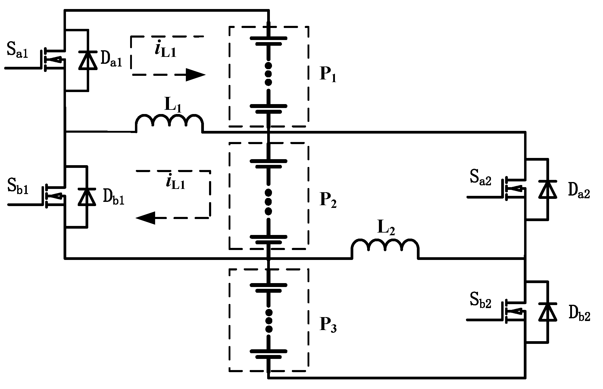
3.1. Equalization Topology

3.1.1. Proposed Equalization Topology

In order to improve the equalization efficiency, simplify the structure of the equalization system, and improve the expansibility of the equalization structure, as shown in Figure 4a, a novel layered bidirectional active equalization topology is proposed. n retired battery cells are grouped into m groups with p cells in each group. In this paper, 12 retired battery cells are grouped into three groups with four cells in each group. The three groups are denoted P1, P2, and P3.
As shown in Figure 4b, a bridge-type equalization topology based on an inductor is adopted in the bottom layer. Each battery group is equipped with a bottom circuit m, consisting of p retired battery cells, 2(p + 1) MOSFET switch tubes, 2 p diodes, and inductor L, can implement energy transfer between any single cell in the battery group and has the advantages of high energy transmission efficiency, a simple circuit structure, and is easy to control.
As shown in Figure 4c, the distributed equalization topological structure based on the bidirectional BUCK-BOOST circuit is adopted in the top layer. Each two adjacent battery groups equipped with one distributed bidirectional balancing circuit, battery group m-1 and battery group m, are equipped with a top circuit named top circuit m − 1. They can implement an energy flow between adjacent battery groups, which makes the equalization system have strong expansibility features and makes them easy to modularize.
The balancing master controller collects retired battery data in real-time and executes the corresponding equalization algorithm, decides in turn whether bottom layer equalization or top layer equalization is needed, and opens or closes the corresponding switches to realize the equalization control of the entire retired battery pack.

3.1.2. Equalization Principle of the Bottom Layer Circuits

Four retired battery cells connected in series were taken as an example to elaborate the equalization principle. It consisted of 4 retired battery cells, 10 MOSFET switch tubes, 8 diodes, and inductor L, and was able to implement energy transfer between any single cell in the group. Inductor L was used as an energy transmission medium between retired batteries in the group. The intragroup energy transfer process can be divided into two stages. Suppose that cell B2 has the highest SOC value and cell B4 has the lowest SOC value, the equalization process with two stages is shown in Figure 5.
Stage 1: charge L. As shown in Figure 5a, the switches S4 and S5 are turned ON, other switches are turned off. Cell B2 charges the inductor L. The inductor L stores energy with the current iL.
Stage 2: discharge L. As shown in Figure 5b, the switches S7 and S10 are turned ON, other switches are turned off. The inductor L charges cell B4, the energy transmission is from inductor L to cell B4.

3.1.3. Equalization Principle of the Top Layer Circuits

Figure 6 shows the equalization process of the top layer circuits, P1, P2, and P3, represent three battery groups. L1 and L2 are energy storage inductors, which can achieve bidirectional energy flow between adjacent retired battery groups. Suppose that the SOC mean value of battery group P1 is higher than battery group P2, the equalization process with two stages is shown in Figure 6.
Stage 1: The switch Sa1 is turned ON, the battery group P1 charges the inductor L1, the energy is stored in inductor L1, the inductor current iL1 is gradually increased from 0 to the maximum.
Stage 2: The switch Sa1 is turned OFF and Sb1 is turned ON, the inductor L1 charges the battery group P2, the energy transmission is from inductor L1 to battery group P2, the inductor current iL1 is gradually reduced from maximum to 0.

3.2. Equalization Algorithm

The performances of the retired batteries have degraded. In order to make a reasonable equalization control strategy, first of all, selecting a parameter that can accurately characterize the charged and discharged conditions of the cells and determine the consistency of the battery pack is needed. In this paper, the SOC is used as the equalization target variable, the battery pack consistency can be judged well, and the differences of the rated capacities of the battery cells are not needed to be considered. The capacity of the battery pack can be fully utilized. A fuzzy unscented Kalman filtering algorithm proposed by our research group was used to estimate the SOCs of retired batteries [32].
Assume that p denotes the battery number of the mth retired battery group, SOCi is the SOC of the ith retired battery, S O C ¯ m is the average SOC of the mth retired battery group, rm is the maximum deviation from the average of the mth retired battery group, SOCavg is the average SOC of the whole retired battery pack, and r denotes the maximum difference between SOCavg and S O C ¯ m :
r m = max ( S O C i S O C m ¯ ) , i = 1 , 2 , , p
r = max ( S O C m ¯ S O C a v g )
Because the consistency between the battery cells in the retired battery pack is poor, if the top layer equalization is carried out firstly, the degree of inconsistency between batteries will be aggravated, and the switching loss during the equalization process will be increased. Therefore, in order to reduce the difficulty of battery equalization and improve the energy utilization efficiency, the strategy of carrying out bottom layer equalization first and top layer equalization second is adopted, which can first ensure the retired batteries in a group are consistent. Figure 7 shows the flowchart of the proposed equalization algorithm. The following steps are used for the proposed equalization algorithm.
(1)
Estimate the SOC of each single retired battery;
(2)
Calculate the S O C ¯ m , rm, SOCavg and r;
(3)
Assume that the set bottom layer equalization threshold value Δm is 0.5%, check the rm, if rm > Δm, go to Step 4, and execute bottom layer equalization algorithm. If rm ≤ Δm, then go to Step 6;
(4)
Carry out bottom layer equalization algorithm. In order to improve the equalization efficiency, the “partition” idea is introduced and equalization paths are optimized. As shown in Figure 8a, according to SOC from low to high, batteries in the same retired battery group are sorted. The SOC values of retired batteries in area a are lower and need to be charged. Area b is divided into area b1 and area b2, the difference between the SOC values of batteries in area b and S O C ¯ m is within the threshold range. The SOC values of retired batteries in area c are higher and need to be discharged.
Which areas the batteries in the mth retired battery group belong to can be expressed by a piecewise function, where i represents the ith retired battery in the mth retired battery group.
i { a , S O C i < S O C m ¯ Δ m b 1 , S O C m ¯ S O C i S O C m ¯ Δ m b 2 , S O C m ¯ < S O C i S O C m ¯ + Δ m c , S O C i > S O C m ¯ + Δ m , i = 1 , 2 , , p
The numbers of retired batteries in areas a, b, and c are denoted Na, Nb, and Nc, respectively, because there are four retired batteries in one battery group. Therefore, according to the different Na, Nb, and Nc, there are the following five cases:
① Case 1: Na = Nc, and Na ≠ 0, Nc ≠ 0. Energy complementary pairs are formed by the retired batteries in area a and area c, batteries in area c discharged, and batteries in area a charged. For example, as shown in Figure 8b, battery B4 and battery B1 exchange energy, battery B3 and battery B2 exchange energy;
② Case 2: Na > Nc, and Na ≠ 0, Nc ≠ 0. Energy complementary pairs are formed by the retired batteries in area a and area c, batteries in area c discharged, and batteries in area a charged. For example, as shown in Figure 8c, the battery with the highest SOC is complementary to two or more than two batteries with lower SOC. The SOC of B4 is highest, B4 transfers energy to B1 and B2;
③ Case 3: Na < Nc, and Na ≠ 0, Nc ≠ 0. Energy complementary pairs are formed by the retired batteries in area a and area c, batteries in area c discharged, and batteries in area a charged. For example, as shown in Figure 8d, the SOC of B1 is lowest, B4, B3, and B2 transfer energy to B1;
④ Case 4: Na = 0, Nc > 0. Energy complementary pairs are formed by the retired batteries in area b1 and area c, batteries in area c discharged, and batteries in area b1 charged. For example, as shown in Figure 8e, retired battery B4 in area c is discharged, retired batteries B1 and B2 in area b1 are charged;
⑤ Case 5: Na > 0, Nc = 0. Energy complementary pairs are formed by the retired batteries in area a and area b2, batteries in area b2 discharged, and batteries in area a charged. For example, as shown in Figure 8f, retired battery B1 in area a is charged, retired batteries B3 and B4 in area b2 are discharged.
(5)
According to the energy complementary pairs established in Step 4, set switching frequency and duty cycle, control the switching of the corresponding MOSFET switch tubes. If rm ≤ Δm, bottom layer equalization has completed and go to Step 6; if rm > Δm, go to Step 4 to continue the bottom layer equalization;
(6)
Assume that the set top layer equalization threshold value Δ is 0.5%, check the r, if r > Δ, go to Step 7 and execute the top layer equalization algorithm; if r ≤ Δ, then go to Step 9;
(7)
Carry out top layer equalization algorithm. The three retired battery groups are sorted according to S O C ¯ m (m = 1, 2, 3) from low to high, and then top layer equalization paths are determined. There are the following six sorting cases: ① S O C ¯ 1 > S O C ¯ 2 > S O C ¯ 3 , ② S O C ¯ 1 > S O C ¯ 3 > S O C ¯ 2 , ③ S O C ¯ 2 > S O C ¯ 1 > S O C ¯ 3 , ④ S O C ¯ 2 > S O C ¯ 3 > S O C ¯ 1 , ⑤ S O C ¯ 3 > S O C ¯ 1 > S O C ¯ 2 , ⑥ S O C ¯ 3 > S O C ¯ 2 > S O C ¯ 1 . It can be divided into two categories: (1) cases ②, ③, ④, and ⑤ belong to direct equalization and transfer energy between adjacent battery groups; case ① and case ⑥ belong to indirect equalization, the battery group P1 and the battery group P3 are not adjacent, the battery group P2 is taken as the energy transmission medium to achieve the equalization between them;
(8)
Check the r. If r > Δ, the retired battery pack is unbalanced, go to Step 7 to continue top layer equalization; if r ≤ Δ, then go to Step 9;
(9)
End of the whole retired battery pack equalization.

4. Simulation and Experimental Verification

In order to verify the proposed equalization method and show the equalization performance, an equalization experiment with selected 12 retired batteries was implemented. The balancing experiment test bench and battery test system are illustrated in Figure 9a,b, respectively. The balancing experiment test bench included battery management system (BMS), master control board, voltage and current detection board, MOSFET switch array, bidirectional BUCK-BOOST circuit, voltage inspection board, retired battery pack, and power. The ITS5300 battery charge and discharge test system was used for battery performance testing. The inductors worked in discontinuous current mode (DCM).

4.1. Static Equalization Experiment

In order to verify the effectiveness of the bottom layer equalization algorithm based on the idea of “partitioning” and the optimization of equalization path, the selected initial states of charge (SOCs) are needed to involve different cases of the bottom layer partitioning equalization algorithm. Table 2 shows the initial SOCs of 12 retired cells for static equalization, three retired battery groups belonging to three different cases of bottom equalization algorithm, and S O C ¯ 1 > S O C ¯ 2 > S O C ¯ 3 . At the beginning of the equalization, the initial SOC range of 12 retired cells was 10.6%, the average of SOCs was 75.458%, r1 was 1.225%, r2 was 2%, r3 was 2.1%, r was 4.058%, maximum deviation from average was 5.442%, and standard deviation was 3.596%. Bottom layer equalization threshold value Δm and top layer equalization threshold value Δ both were set to 0.5%.
The static equalization process lasted for two hours. Figure 10a illustrates the SOC response. It was observed that the differences between the retired cells’ SOCs gradually converged, bottom layer equalization time was about 1100 s, equalization times of battery group P1, battery group P2 and battery group P3 were 960 s, 1080 s, and 1100 s, respectively, top layer equalization phase was 1100 s–6060 s, equalization time of the whole retired battery pack was about 6060 s; as shown in Table 4, at the end of the equalization, the SOC range was decreased to 1.6%, the average of SOCs was 74.841%, maximum deviation from average was decreased to 0.92%, and standard deviation was decreased to 0.531%, r was decreased to 0.464%. The charge transfer efficiency of static equalization was 63.83%.

4.2. Charging Equalization Experiment

Table 3 shows the initial SOCs of 12 retired cells for charging equalization, three retired battery groups belonging to three different cases of bottom equalization algorithm, and S O C ¯ 1 > S O C ¯ 2 > S O C ¯ 3 . At the beginning of equalization, the initial SOC range of 12 retired cells was 13.9%, the average of SOCs was 43.77%, r1 was 0.775%, r2 was 3.6%, r3 was 2.125%, r was 5.345%, maximum deviation from average was 7.47%, and standard deviation was 4.6%. Bottom layer equalization threshold value Δm and top layer equalization threshold value Δ both were set to 0.5%.
The charging equalization process lasted for 1.5 h. Figure 10b illustrates the SOC response. It was observed that the differences between the retired cells’ SOCs gradually converged during the charging process. Bottom layer equalization time was about 2625 s, equalization time of the whole retired battery pack was about 4925 s; as shown in Table 4, at the end of the equalization, the SOC range was decreased to 1.41%, the average of SOCs was 86.91%, maximum deviation from average was decreased to 0.87%, and standard deviation was decreased to 0.42%, r was decreased to 0.467%. The charge transfer efficiency of charging equalization was 63.18%.

5. Conclusions

This paper proposes a layered bidirectional active equalization method based on the SOC of batteries. The main concluding remarks can be made below:
(1) Power lithium-ion batteries retired from EVs can be used for energy storage applications. Moreover, a layered bidirectional active equalization topology is introduced for retired battery equalization, which can be used for the equalization of a large number of retired batteries. Equalization is based on the SOC of cells, and a bottom layer equalization algorithm based on the “partition” idea and route optimization is proposed;
(2) The balancing experiment test bench is developed and an ITS5300 battery test system is used for static equalization of 12 retired batteries and a charge equalization experiment. The experiment results have verified the proposed equalization method is effective, although the selected initial SOCs for static and charge equalization have a large range and involve different cases of the bottom layer partitioning equalization algorithm. The equalization time is short and the consistency of the retired battery pack is greatly improved. The SOC range of 12 retired cells is decreased from 10.6% to 1.6% and from 13.9% to 1.41% after static equalization and charge equalization, respectively;
(3) Although the equalization charge transfer efficiency is moderate, improved consistency is much more important for retired batteries, and the retired battery pack has a much larger available capacity after equalization, which is more critical for a second-use retired battery pack for energy storage.

Author Contributions

Conceptualization, Y.S. and W.L.; data curation, Y.Y.; formal analysis, Y.Y.; funding acquisition, C.X. and Z.T.; investigation, W.Z.; methodology, W.Z.; project administration, F.L.; software, Y.Y.; supervision, C.X.; validation, Y.S. and W.L.; writing—original draft preparation, Y.Y.; writing—review and editing, C.X. and Y.S. All authors have read and agreed to the published version of the manuscript.

Funding

This research was funded by the National Natural Science Foundation of China, grant number 51977164; the Hubei Science Fund for Distinguished Young Scholars, grant number 2017CFA049; and the Hubei province technological innovation major project, grant number 2018AAA059.

Conflicts of Interest

The authors declare no conflicts of interest.

References

  1. Xie, C.; Xu, X.; Bujlo, P.; Shen, D.; Zhao, H.; Quan, S. Fuel cell and lithium iron phosphate battery hybrid powertrain with an ultracapacitor bank using direct parallel structure. J. Power Sources 2015, 279, 487–494. [Google Scholar] [CrossRef]
  2. Farmann, A.; Sauer, D.U. A comprehensive review of on-board State-of-Available-Power prediction techniques for lithium-ion batteries in electric vehicles. J. Power Sources 2016, 329, 123–137. [Google Scholar] [CrossRef]
  3. Li, X.; Xie, C.; Quan, S.; Huang, L.; Fang, W. Energy management strategy of thermoelectric generation for localized air conditioners in commercial vehicles based on 48 V electrical system. Appl. Energy 2018, 231, 887–900. [Google Scholar] [CrossRef]
  4. Wang, Y.; Zhang, C.; Chen, Z. An adaptive remaining energy prediction approach for lithium-ion batteries in electric vehicles. J. Power Sources 2016, 305, 80–88. [Google Scholar] [CrossRef]
  5. Jiang, Y.; Jiang, J.; Zhang, C.; Zhang, W.; Gao, Y.; Guo, Q. Recognition of battery aging variations for LiFePO4 batteries in 2nd use applications combining incremental capacity analysis and statistical approaches. J. Power Sources 2017, 360, 180–188. [Google Scholar] [CrossRef]
  6. Liao, Q.; Mu, M.; Zhao, S.; Zhang, L.; Jiang, T.; Ye, J.; Shen, X.; Zhou, G. Performance assessment and classification of retired lithium ion battery from electric vehicles for energy storage. Int. J. Hydrog. Energy 2017, 42, 18817–18823. [Google Scholar] [CrossRef]
  7. Lai, X.; Qiao, D.; Zheng, Y.; Ouyang, M.; Han, X.; Zhou, L. A rapid screening and regrouping approach based on neural networks for large-scale retired lithium-ion cells in second-use applications. J. Clean Prod. 2019, 213, 776–791. [Google Scholar] [CrossRef]
  8. China Energy Storage Alliance. Energy Storage Industry Research White Paper 2019. Available online: http://www.cnesa.org/index/inform_detail?cid=5cf0ef98b1fd3772048b4567 (accessed on 18 May 2019).
  9. Zhang, Y.; Li, Y.; Tao, Y.; Ye, J.; Pan, A.; Li, X.; Liao, Q.; Wang, Z. Performance assessment of retired EV battery modules for echelon use. Energy 2020, 193, 116555. [Google Scholar] [CrossRef]
  10. Debnath, U.K.; Ahmad, I.; Habibi, D. Quantifying economic benefits of second life batteries of gridable vehicles in the smart grid. Int. J. Electr. Power Energy Syst. 2014, 63, 577–587. [Google Scholar] [CrossRef]
  11. Neubauer, J.; Pesaran, A. The ability of battery second use strategies to impact plug-in electric vehicle prices and serve utility energy storage applications. J. Power Sourcesces 2011, 196, 10351–10358. [Google Scholar] [CrossRef]
  12. Debnath, U.K.; Ahmad, I.; Habibi, D. Gridable vehicles and second life batteries for generation side asset management in the Smart Grid. Int. J. Electr. Power Energy Syst. 2016, 82, 114–123. [Google Scholar] [CrossRef]
  13. Madlener, R.; Kirmas, A. Economic Viability of Second Use Electric Vehicle Batteries for Energy Storage in Residential Applications. Energy Procedia 2017, 105, 3806–3815. [Google Scholar] [CrossRef]
  14. Huang, W.; Abu Qahouq, J.A. Energy Sharing Control Scheme for State-of-Charge Balancing of Distributed Battery Energy Storage System. IEEE Trans. Ind. Electron. 2015, 62, 2764–2776. [Google Scholar] [CrossRef]
  15. Zhang, C.; Shang, Y.; Li, Z.; Cui, N. An Interleaved Equalization Architecture with Self-Learning Fuzzy Logic Control for Series-Connected Battery Strings. IEEE Trans. Veh. Technol. 2017, 66, 10923–10934. [Google Scholar] [CrossRef]
  16. Gallardo-Lozano, J.; Romero-Cadaval, E.; Milanes-Montero, M.I.; Guerrero-Martinez, M.A. A novel active battery equalization control with on-line unhealthy cell detection and cell change decision. J. Power Sourcesces 2015, 299, 356–370. [Google Scholar] [CrossRef]
  17. Liu, X.; Wan, Z.; He, Y.; Zheng, X.; Zeng, G.; Zhang, J. A Unified Control Strategy for Inductor-Based Active Battery Equalisation Schemes. Energies 2018, 11, 405. [Google Scholar] [CrossRef] [Green Version]
  18. Gallardo-Lozano, J.; Romero-Cadaval, E.; Milanes-Montero, M.I.; Guerrero-Martinez, M.A. Battery equalization active methods. J. Power Sourcesces 2014, 246, 934–949. [Google Scholar] [CrossRef]
  19. Bouchhima, N.; Schnierle, M.; Schulte, S.; Birke, K.P. Active model-based balancing strategy for self-reconfigurable batteries. J. Power Sourcesces 2016, 322, 129–137. [Google Scholar] [CrossRef]
  20. Daowd, M.; Antoine, M.; Omar, N.; van den Bossche, P.; van Mierlo, J. Single Switched Capacitor Battery Balancing System Enhancements. Energies 2013, 6, 2149–2174. [Google Scholar] [CrossRef] [Green Version]
  21. Chen, Y.; Liu, X.; Cui, Y.; Zou, J.; Yang, S. A Multi-Winding Transformer Cell-to-Cell Active Equalization Method for Lithium-Ion Batteries with Reduced Number of Driving Circuits. IEEE Trans. Power Electron. 2016, 31, 4916–4929. [Google Scholar] [CrossRef]
  22. Wang, Y.; Zhang, C.; Chen, Z.; Xie, J.; Zhang, X. A novel active equalization method for lithium-ion batteries in electric vehicles. Appl. Energy 2015, 145, 36–42. [Google Scholar] [CrossRef]
  23. Hannan, M.A.; Hoque, M.M.; Peng, S.E.; Uddin, M.N. Lithium-Ion Battery Charge Equalization Algorithm for Electric Vehicle Applications. IEEE Trans. Ind. Appl. 2017, 53, 2541–2549. [Google Scholar] [CrossRef]
  24. Dai, H.; Wei, X.; Sun, Z.; Wang, D. A novel dual-inductor based charge equalizer for traction battery cells of electric vehicles. Int. J. Electr. Power Energy Syst. 2015, 67, 627–638. [Google Scholar] [CrossRef]
  25. Cui, X.; Shen, W.; Zhang, Y.; Hu, C. A Fast Multi-Switched Inductor Balancing System Based on a Fuzzy Logic Controller for Lithium-Ion Battery Packs in Electric Vehicles. Energies 2017, 10, 1034. [Google Scholar] [CrossRef] [Green Version]
  26. Zheng, X.; Liu, X.; Yao, H.; Zeng, G. Active vehicle battery balancing scheme in the condition of constant-voltage/current charging and discharging. IEEE Trans. Veh. Technol. 2017, 66, 3714–3723. [Google Scholar] [CrossRef]
  27. Wu, Z.; Ling, R.; Tang, R. Dynamic battery equalization with energy and time efficiency for electric vehicles. Energy 2017, 141, 937–948. [Google Scholar] [CrossRef]
  28. Zhang, Z.; Gui, H.; Gu, D.; Yang, Y.; Ren, X. A Hierarchical Active Balancing Architecture for Lithium-Ion Batteries. IEEE Trans. Power Electron. 2017, 32, 2757–2768. [Google Scholar] [CrossRef]
  29. Ouyang, Q.; Chen, J.; Zheng, J.; Hong, Y. SOC Estimation-Based Quasi-Sliding Mode Control for Cell Balancing in Lithium-Ion Battery Packs. IEEE Trans. Ind. Electron. 2018, 65, 3427–3436. [Google Scholar] [CrossRef]
  30. Ma, Y.; Duan, P.; Sun, Y.; Chen, H. Equalization of Lithium-Ion Battery Pack Based on Fuzzy Logic Control in Electric Vehicle. IEEE Trans. Ind. Electron. 2018, 65, 6762–6771. [Google Scholar] [CrossRef]
  31. Diao, W.; Xue, N.; Bhattacharjee, V.; Jiang, J.; Karabasoglu, O.; Pecht, M. Active battery cell equalization based on residual available energy maximization. Appl. Energy 2018, 210, 690–698. [Google Scholar] [CrossRef]
  32. Zeng, M.; Zhang, P.; Yang, Y.; Xie, C.; Shi, Y. SOC and SOH Joint Estimation of the Power Batteries Based on Fuzzy Unscented Kalman Filtering Algorithm. Energies 2019, 12, 3122. [Google Scholar] [CrossRef] [Green Version]
Figure 1. Voltage distribution of 50 retired batteries.
Energies 13 00832 g001
Figure 2. Post-charge voltage of 36 retired batteries.
Energies 13 00832 g002
Figure 3. New rated capacity distribution of 30 retired batteries.
Energies 13 00832 g003
Figure 4. (a) Structure of the proposed bidirectional equalizer, (b) structure of bottom layer balancing circuit, (c) structure of top layer balancing circuit.
Energies 13 00832 g004
Figure 5. The equalization process of a bottom layer equalization circuit. (a) Charge L, (b) discharge L.
Energies 13 00832 g005
Figure 6. The equalization process of top layer equalization circuit.
Energies 13 00832 g006
Figure 7. Flowchart of the proposed equalization algorithm.
Energies 13 00832 g007
Figure 8. Partition and equalization path sketch maps. (a) Batteries partition sketch map, (b) equalization path of Case 1, (c) equalization path of Case 2, (d) equalization path of Case 3, (e) equalization path of Case 4, (f) equalization path of Case 5.
Energies 13 00832 g008
Figure 9. (a) Balancing experiment test bench, (b) battery test system.
Energies 13 00832 g009
Figure 10. (a) SOC response with 12 retired cells of static equalization, (b) SOC response with 12 retired cells of charging equalization.
Energies 13 00832 g010
Table 1. New rated capacities of the selected 12 retired cells.
Number169301917294222025183
CellB1B2B3B4B5B6B7B8B9B10B11B12
Capacity (Ah)33.432.432.331.631.231.130.930.730.730.630.529.8
Table 2. The initial SOCs of 12 retired cells for static equalization.
GroupsP1P2P3
CellsB1B2B3B4B5B6B7B8B9B10B11B12
SOC (%)80.980.678.578.777.374.973.675.473.571.270.370.6
Table 3. The initial SOCs of 12 retired cells for charging equalization.
GroupsP1P2P3
CellsB1B2B3B4B5B6B7B8B9B10B11B12
SOC (%)50.248.148.348.847.642.544.94140.238.736.338.5
Table 4. Consistency comparison of retired battery pack before and after equalization.
SOC Range (%)SOCavg (%)Maximum Deviation from Average (%) Standard Deviation (%)Equalization Time (s)Charge Transfer Efficiency (%)
Static equalization 606063.83
Before equalization10.675.4585.4423.596
After equalization1.674.8410.920.531
Charging equalization 492563.18
Before equalization13.943.777.474.6
After equalization1.4186.910.870.42

