Article

The Performance of the BTB-VSC for Active Power Balancing, Reactive Power Compensation and Current Harmonic Filtering in the Interconnected Systems

1
Facultad de IngenieríaElectromecánica, Universidad de Colima, El Naranjo 28060, Colima, Mexico
2
Centro de Investigación y Estudios de Posgrado, Facultad de Ingeniería, Universidad Autónoma de San Luis Potosí, San Luis 78300, Mexico
3
Universität Kassel Kompetenzzentrum für Dezentrale Elektrische Energieversorgungstechnik (KDEE), 34121 Kassel, Germany
*
Author to whom correspondence should be addressed.
Energies 2020, 13(4), 831; https://doi.org/10.3390/en13040831
Submission received: 7 January 2020 / Revised: 3 February 2020 / Accepted: 12 February 2020 / Published: 14 February 2020
(This article belongs to the Special Issue Harmonics and Quality of Power)

Abstract

:
Nowadays, the use of power converters to control active and reactive power in AC–AC grid-connected systems has increased. With respect to indirect AC–AC converters, the tendency is to enable the back-to-back (BTB) voltage source converter (VSC) as an active power filter (APF) to compensate current harmonics. Most of the reported works use the BTB-VSC as an auxiliary topology that, combined with other topologies, is capable of active power regulation, reactive power compensation and current harmonic filtering. With the analysis presented in this work, the framework of the dynamics associated with the control loops is established and it is demonstrated that BTB-VSC can perform the three tasks for which, in the reviewed literature, at least two different topologies are reported. The proposed analysis works to support the performance criteria of the BTB-VSC when it executes the three control actions simultaneously and the total current harmonic distortion is reduced from 27.21% to 6.16% with the selected control strategy.

1. Introduction

In recent years, the use of power converters to control active and reactive power in AC–AC grid-connected systems has increased. Basically, the power converter is used to control the power flow between two AC sources with the same or different electrical characteristics [1,2,3,4]. However, the selection of the topology depends on the power application and the type of interfacing bus. Among the wide variety of existing AC–AC converters there are: (a) the conventional AC–AC converters which employ a voltage or current DC interfacing bus between the two stages, these converters are known as two-level, indirect AC–AC converters and (b) the direct AC–AC converters, which achieve the AC–AC conversion without an intermediate energy storage element [1].
Regarding indirect AC–AC converters, the back-to-back (BTB) power converter formed by voltage source converters (VSC) is one of the most attractive topologies. The BTB-VSC converter consists in two VSCs connected through a common DC bus voltage that allows the VSCs can be controlled separately. Both VSCs can operate as a rectifier or an inverter. In most of the practical applications, the BTB-VSC converter is operated to regulate the active power between two AC–AC grid-connected sources. The properties of this combination are well-known: the BTB-VSC is used to supply an unitary power factor at each AC side; the DC bus voltage is generally higher than the peak AC source voltage for proper operation during the rectification with power factor correction; the inverter is responsible for delivering a regulated AC output, making it possible to control the power flow of the interconnected AC–AC systems [5,6,7]. The active power can be transferred from one AC source to the other, while the DC bus voltage is suitably regulated [5], also, the BTB-VSC allows the interconnection of two asynchronous AC–AC grid-connected systems and contributes to preventing cascaded failures and eliminating part the of inter-area oscillations in the AC–AC grid-connected systems [7]. Among the main applications in which the BTB-VSC is reported are: (1) traditionally, AC motor drives, high voltage direct current (HVDC) transmission systems and unified power quality conditioners (UPQC); (2) in recent years, wind energy conversion systems (WECS) and marine energy conversion systems (MAECS) [8,9,10,11,12,13,14,15,16,17,18,19,20,21,22]. The BTB-VSC is also used in some power applications as an auxiliary converter connected in shunt to AC–AC systems for reactive power compensation or current harmonic filtering, therefore it is considered as an extended version of the STATCOM and a member or multi-converter flexible AC transmission systems (FACTS) family, meaning that two or more converters can be coupled through the DC bus [23,24,25].
Recently, the tendency has been to enable the BTB-VSC to act not only as a power flow controller, but also as an active power filter (APF) to compensate current harmonics [26,27,28,29,30,31]. In [26], an APF compensator converter is implemented with a single-phase BTB-VSC; the main idea of this work is to use the BTB-VSC as a power flow controller to solve the power quality problems of electric railway power systems. Basically, the single-phase BTB-VSC is used to regulate the active power between the interconnected AC systems and to compensate the reactive power. The current harmonic filtering is also executed; however, to develop these tasks the system requires several combinations. Swami and Singh [27] propose a doubly fed induction generator (DFIG)-based WECS with integrated active filter capabilities. The system incorporates two BTB-VSCs and they are placed between the rotor and the grid. Current harmonics generated by nonlinear loads at the point of common coupling (PCC) are mitigated by the grid-side controllers, so that the stator and grid currents are harmonic-free. Rotor-side controllers are used for maximum power point tracking (MPPT) and power factor correction at the stator side; the control scheme is implemented using voltage-oriented control (VOC). Results demonstrate that grid current and stator current total harmonic distortion (THDc) are less than 5% as per IEEE-519 standard [28]. In fact, this type of configuration is the most used for WECS and MAECS [6,12,18,19,20,21,22]. To achieve the objectives described above, control of the BTB-VSC is developed considering synchronous coordinates such as the rotating (dq0) [6,7,12,14,15,18,22,25,27,31] and stationary (αβ0) [17,23,29,31], as well as the time-domain or conventional (abc) [9,26,30], reference frame. Typically, depending on the used reference frame, the adopted control structure is chosen. For rotating and stationary reference frames, the cascade control is generally used by nesting two control loops. The inner loop is named a secondary loop whereas the outer loop is considered a primary loop [32]. For the control of the BTB-VSC, the control tasks are distributed as follows: the inner loops are used to control the current, whereas the outer loops are used to provide a reference for the inner loops. Outer loops are fixed considering active power (P), reactive power (Q), voltage or frequency. The inner loop must respond much faster than the outer loop, such that the primary controller that regulates the primary variable can send a suitable set-point to the inner loop [33]. The inner loop should be faster than the outer loop, the typical rule of thumb is that the average response times should have a ratio of at least 5 [12]. However, for power converters the compromise is linked to the switching frequency [5,33] and this is one of the most important restrictions that must be considered when the BTB-VSC is proposed to attenuate or reproduce the current harmonics.
Most of the reported works use the BTB-VSC as an auxiliary topology, that combined with other proposed topology, is capable of active power transmission, reactive power compensation, voltage or frequency control and current harmonic compensation [26,29,30,31]. Certainly, each one of the reviewed topologies has advantages and disadvantages that can be addressed from different points of view and it is not the objective of this work to compare them. This paper aims to comprehensively analyze the classical configuration of the BTB-VSC to execute active power regulation and reactive power compensation, and current harmonic filtering at the same time. Furthermore, despite the fact that several controllers have been proposed in the literature to control power converters, the most widely used controller is still the proportional-integral (PI) controller [1], because with the proper tuning of the PI controller the desired closed-loop performance can be achieved; therefore, this scheme is adopted. With the presented analysis, the framework of the dynamics associated with control loops is stablished and it is demonstrated that the BTB-VSC can perform the three tasks for which, in the reviewed literature, at least two different topologies are reported.
The proposed analysis works to support the performance criteria of the BTB-VSC when it executes the three control actions simultaneously, and the total current harmonic distortion is reduced from 27.21% to 6.16% with the selected control strategy. Simulation results for the different evaluated cases corroborate the advantages provided by the BTB-VSC to perform the desired control tasks. The proposed system is evaluated with a 30 kVA laboratory prototype.

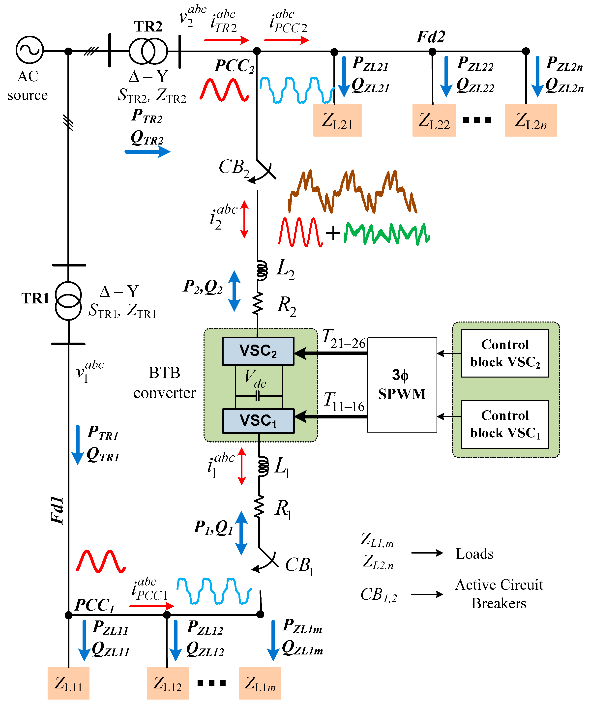
2. System Description and Analysis

Figure 1 shows the integrated elements considered when analyzing the proposal of this work. Transformers TR1 and TR2 are connected to the main AC source and they supply the distribution feeders Fd1 and Fd2, respectively. The loads (linear and nonlinear) are represented by ZL1,m and ZL2,n and they are situated at different locations for Fd1 and Fd2. The BTB-VSC is composed by two VSCs, sharing a common DC bus voltage (vdc) and coupled to Fd1 and Fd2 through R1,2 and L1,2. Each VSC is synchronized with the respective AC side and v1abc and v2abc represent the phase voltages. To simplify the analysis, subscripts 1 and 2 will be associated to the VSC, as shown in Figure 1. The active power can be regulated in both directions. Furthermore, the BTB-VSC can generate a controlled output with lagging power factor or leading power factor at both AC sides [5]. For the analysis, a balanced, harmonic-free, three-phase system is assumed as the AC source. To exchange active power from Fd1 to Fd2 and vice versa, each one of these transformers must have the capacity to deliver power to the other side, besides feeding their own loads connected at the corresponding PCC.
The controllable bypass switches CB1 and CB2, shown in Figure 1, are closed according to the power compensation requirements dictated by the control block. i1abc and i2abc represent the grid currents at the output of VSC1 and VSC2. IPCC1,2abc are the total currents absorbed by the linear and nonlinear loads at the corresponding PCC. The total current harmonic distortion (THDc) is compensated through the BTB-VSC by injecting the necessary current harmonic at the associated connecting point.
There are different techniques for current harmonic filtering of nonlinear loads; in [34,35], three methodologies are studied and compared. The first proposed methodology determines the current reference required by the VSC, using the instantaneous reactive power theory. The second one obtains the current components in the DQ synchronous reference frame, and the third one considers following a sinusoidal current with unitary power factor. The results emphasize that the performance is alike for ideal conditions; however, it is determined that, for voltage unbalances or voltage distortion, the synchronous reference frame largesse has the best performance, due to the fact that the system is unaffected by voltage disturbances [3].

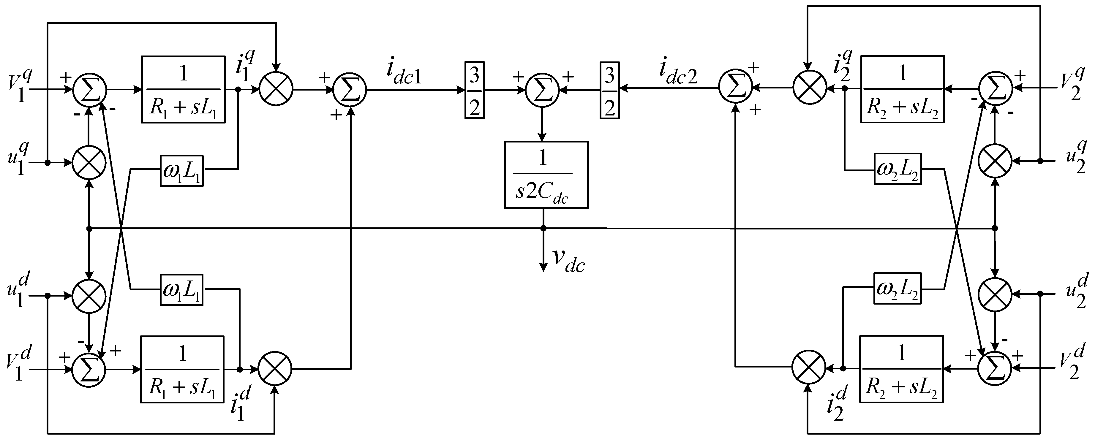
2.1. Modeling of the BTB-VSC Converter

In this work, the DQ transformation is adopted to obtain the mathematical model of the BTB-VSC, d component is associated to the active power and q component to the reactive power. To obtain the DQ model, a three-phase three-wire system without voltage harmonics is considered. Besides, the effect of the switching harmonics is neglected [5]. The DQ transformation is coordinated with the connected AC source, rotating at ω (ω = 2πf, where f is the electrical frequency of the AC source). The d axis chosen aligned with the corresponding AC side, therefore, V1,2d becomes equal to the amplitude of v1abc and v2a, respectively; V1,2q are zero. However, this decision is arbitrary: for representation purposes both variables are used to denote the model. The governing Equations of the normalized DQ model can be written as given, from Equations (1)–(5).
d i 1 d d t = R 1 L 1 i 1 d + ω 1 i 1 q + 1 L 1 v 1 d 1 2 L 1 v d c u 1 d
d i 1 q d t = R 1 L 1 i 1 q ω 1 i 1 d + 1 L 1 v 1 q 1 2 L 1 v d c u 1 q
d i 2 d d t = R 2 L 2 i 2 d + ω 2 i 2 q + 1 L 2 v 2 d 1 2 L 2 v d c u 2 d
d i 2 q d t = R 2 L 2 i 2 q ω 2 i 2 d + 1 L 2 v 2 q 1 2 L 2 v d c u 2 q
C d c d v d c d t = 3 4 [ ( u 1 d i 1 d + u 1 q i 1 q ) + ( u 2 d i 2 d + u 2 q i 2 q ) ]
u1d,q and u2d,q represent the control inputs and i1d,q and i2d,q are the currents injected by the BTB-VSC at the corresponding PCC. The linear expressions for active and reactive power terms are defined by
P 1 , 2 = 3 2 ( v 1 , 2 d i 1 , 2 d + v 1 , 2 q i 1 , 2 q )
Q 1 , 2 = 3 2 ( v 1 , 2 q i 1 , 2 d V 1 , 2 d i 1 , 2 q )
A block diagram representation of Equations (1)–(5) is delineated in Figure 2. As observed, there are cross-coupling terms among d and q components. These problems are generally resolved by adding feedforward terms to the control loop in order to cancel the nonlinearities of the system [36]. When the DQ transformation is performed on nonlinear signals, the harmonic profile is mapped as an AC signal and added to the DC signals (d and q components) as shown in Figure 3 [37].
From Equation (6), it has to be considered that
P 1 = P 2
to guarantee the power balance. Hence, through the control of the dq current components, it is possible to control the active and reactive power.
To evaluate the performance of the BTB-VSC, it is necessary to define the control objective. Besides, in order to simplify the control design for each VSC, four main goals are defined as follows: (1) regulating active power at the output of the VSCs or among feeders; (2) compensating reactive power (for lagging or leading PF) at the output terminals of VSC1 and VSC2. This can be a portion of the total reactive power required by the loads or even the total amount, depending on the power capacity of the BTB-VSC; (3) compensating current harmonics demanded by the nonlinear loads at the corresponding PCC, and (4) maintaining the DC bus voltage regulated. For the analysis, it is considered that VSC1 and VSC2 share a common DC bus voltage. It is important to make it clear that both VSCs can achieve any of these tasks. However, commonly, the VSC coupled to the most reliable AC system is used to regulate the DC bus voltage. For the configuration proposed in Figure 1, the selection can be set arbitrarily, hence the DC bus voltage regulation is assigned to VSC1, so that VSC2 is chosen to regulate the active power. Reactive power regulation is realized by the corresponding VSC.

2.2. PQ Operating Modes
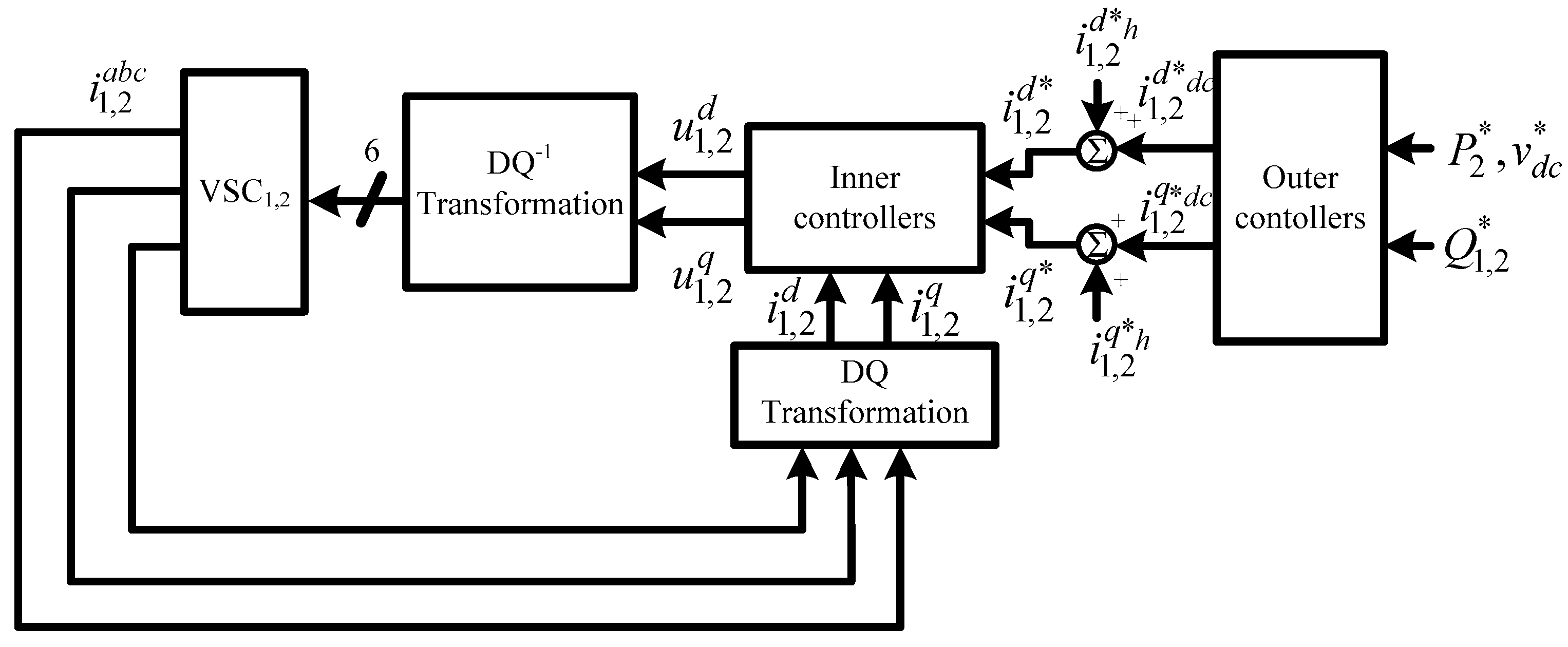
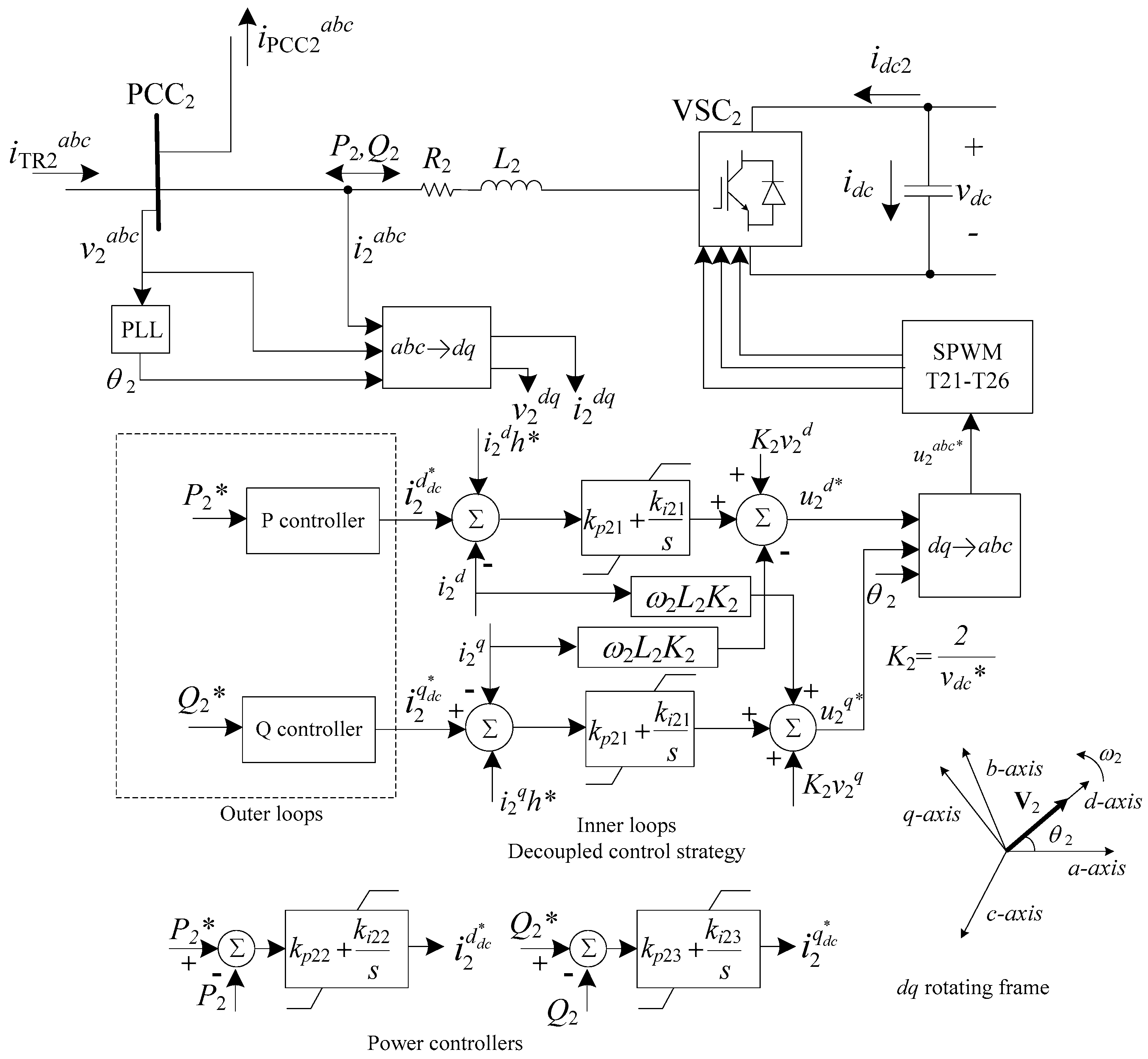
The BTB-VSC in Figure 1 can operate in eight modes for the control of P and Q, as described in Table 1. States 1 and 0 represent the ON and OFF states, respectively. As described in [5], Case 1 represents the null condition. Cases 2 through 7 are derived from the combination of Case 8. Scenarios based on Cases 5 and 8 are explained as examples. Considering Table 1, Case 5 takes place when the active power regulation is achieved, for this case, the BTB-VSC can regulate the active power; basically, it is used to deliver active power from one AC side to the other AC side. Therefore, it takes power from one transformer (considered as a sub-utilized transformer) and supplies it to the other one (sometimes considered as an overloaded transformer). Unlike Case 5, in Case 8 the BTB-VSC, besides the active power regulation, also compensates reactive power at the output terminals of both VSCs. Due to the BTB-VSC being constructed by two VSCs, the maximum active power transferred among feeders is fixed by the VSC with a lower capacity. Instead, reactive power is bound by the passive components and the DC bus voltage, reducing the available rating for reactive power compensation. Another important point that must be considered is the combination of active and reactive powers; they cannot be set indiscriminately, they must achieve the constraint imposed by the (P, Q) pair for the bounded area.

3. Control Strategy

The general block diagram shown in Figure 4 is proposed for control of the BTB-VSC. To regulate active power, compensate reactive power and filtering current harmonics, the BTB-VSC must generate a dq current component at the corresponding PCC, as given below,
i 1 , 2 d = i 1 , 2 d d c + i 1 , 2 d h
i 1 , 2 q = i 1 , 2 q d c + i 1 , 2 q h
where i1d estimates the amount of power required to keep the DC voltage stable and regulated. i2d indicates the magnitude and direction of the active power to be controlled between Fd1 and Fd2. On the other hand, both i1q and i2q specify the required reactive power at the corresponding PCC. i1,2dh and i1,2qh represent the current harmonic components the BTB-VSC must generate to compensate the current harmonics caused by nonlinear loads. P2*, vdc* and Q1,2* are the reference for active power, DC bus voltage and reactive power; i1,2d* and i1,2q* are the current reference.
Figure 5 shows the proposed block diagram to obtain the current harmonic content of nonlinear loads. This method detects the line currents iPCC1,2abc flowing downstream of the PCC1,2. These currents are introduced to a DQ transformation block to obtain iPCC1,2d,q. The obtained dq signals contain DC and AC terms; therefore, a low-pass-filter (LPF) is implemented to separate the DC and AC terms from iPCC1,2d,q. The LPF provides the current harmonic references i1,2d*h and i1,2q*h. For this proposal, a second order filter provides the required attenuation response; therefore, a Butterworth filter is used.
For the inner control loops, a current control technique that allows the cancelation of the cross-coupling terms is adopted. According to the literature, this technique is known by different names, usually depending on the application. For PWM-VSC, it can be found mainly as decoupled control, decoupled power control or feed-forward decoupling control strategy. For space vector modulation converters, it is related as direct control or direct current control strategy and for distributed generators in the islanded mode, it is adapted as a droop control strategy [38,39,40,41,42].
For the design of the BTB-VSC controllers, it is considered that VSC1 and VSC2 are decoupled; therefore, they can be controlled independently from each other. Figure 6 shows the control block diagram for VSC2; the control block diagram for VSC1 uses a similar arrangement. For the proposed control scheme, a positive P indicates that the active power goes from TR1 to TR2; a negative P represents the opposed case. A positive Q specifies a lagging power factor (PF) and a negative Q designates a leading PF. The plant model of the inner loops is established according to Equations (1) through (4), and the control laws given from Equations (11) through (14) are proposed for the current controllers of VSC1 and VSC2. υ11, υ12, υ21, and υ22 are auxiliary control signals which contain the PI controllers. The control laws allow the local cancelation of the nonlinearities and the cross-coupling terms in order to regulate the active power, compensate the reactive power and compensate the current harmonic distortion.
u 1 d = 2 v d c * ( ω 1 L 1 i 1 q * R 1 i 1 d * + v 1 d ) υ 11
u 1 q = 2 v d c * ( ω 1 L 1 i 1 d * R 1 i 1 q * + v 1 q ) υ 12
u 2 d = 2 v d c * ( ω 2 L 2 i 2 q * R 2 i 2 d * + v 2 d ) υ 21
u 2 q = 2 v d c * ( ω 2 L 2 i 2 d * R 2 i 2 q * + v 2 q ) υ 22
The closed-loop transfer functions are expressed as:
i 1 d , q ( s ) i 1 d , q * ( s ) = k p 11 s + k i 11 s 2 + k p 11 s + k i 11 i 2 d , q ( s ) i 2 d , q * ( s ) = k p 21 s + k i 21 s 2 + k p 21 s + k i 21
The DC bus voltage dynamic is established using Equation (5) and is given by (16).
C d c d v d c d t = I d c 2 + 3 i 1 d * 2 v d c * ( ω 1 L 1 i 1 q * R 1 i 1 d * + v 1 d ) 3 2 i 1 d * υ 11 + 3 i 1 q * 2 v d c * ( ω 1 L 1 i 1 d * + v 1 q ) 3 2 i 1 q υ 21
as long as the current space-states tend to the references value i1di1d* and i1qi1q*. That is, the stabilization error approaches to zero. Then, the auxiliary control signals tend to zero, υ11 → 0 and υ12 → 0.
Rearranging Equation (16), it is found that:
C d c d v d c d t = 1 v d c * [ P 1 P 2 P l o s s e s ]
where, P 1 = 3 2 ( v 1 d i 1 d + v 1 q i 1 q ) , P2 is the output power and it must fulfill P 2 = P 1 and Plosses represents the power dissipated by R1,2.
Equation (17) states that, if the power grid supplies the power demanded by the load and also absorbs all the power and commutation losses, then the indirect control of the DC bus voltage is stable and the trajectory d v d c * d t 0 , with which, v d c v d c * , as long as i 1 d i 1 d * and i 1 q i 1 q * . The closed-loop transfer function for the DC bus voltage is given by
v d c ( s ) v d c * ( s ) = v 1 d ( k p 13 s + k i 13 ) 2 3 C d c v d c * s 2 + k p 13 v 1 d s + k i 13 v 1 d

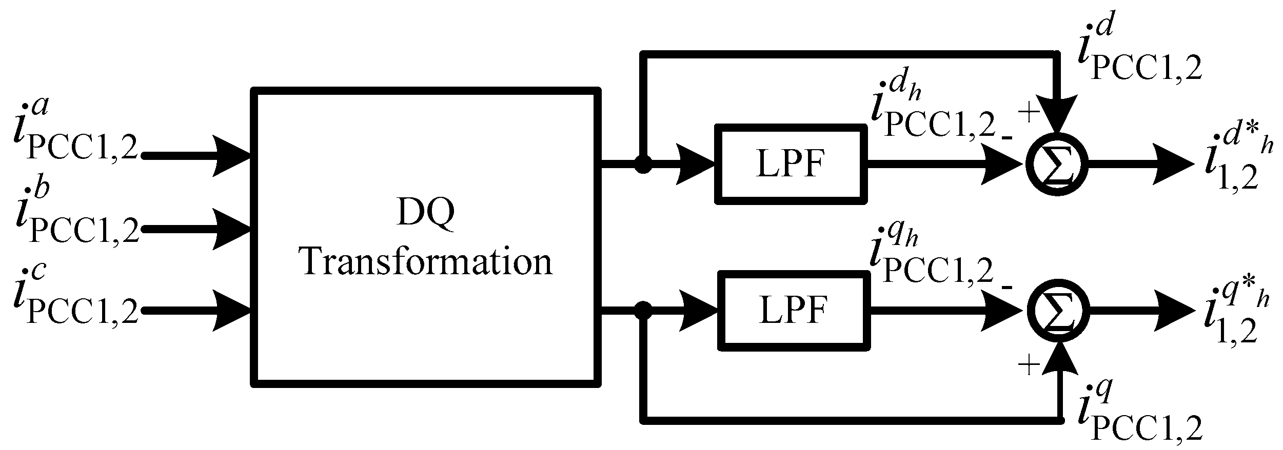
3.1. Controllers Design

To guarantee that inner and outer loops are decoupled, the PI controllers must accomplish the bandwidth criteria, as described in Section 1, in order to achieve a good reference tracking performance and fast response. The switching frequency (fsw) is set at 4.86 kHz. Considering Equation (15), dq current controllers have similar dynamics; therefore, the bandwidth of both controllers is set at 478 Hz. The bandwidth of the DC bus voltage is fixed at 14 Hz. The bandwidths are stablished by using the values listed in Table 2. The proportional and integral coefficients of the PI controllers kp11,21 and kp11,21 are selected as 1 and 120, respectively.
The closed-loop transfer functions that describe the reference tracking of the outer loops are derived, as shown in Equations (19)–(21).
Q 1 ( s ) Q 1 * ( s ) = v 1 d ( k p 14 s + k i 14 ) ( 2 3 k p 14 v 1 d ) s k i 14 v 1 d
P 2 ( s ) P 2 * ( s ) = v 2 d ( k p 22 + k i 22 ) ( 2 3 + k p 22 v 2 d ) s + k i 22 v 2 d
Q 2 ( s ) Q 2 * ( s ) = v 2 d ( k p 23 s + k i 23 ) ( 2 3 k p 23 v 2 d ) s k i 23 v 2 d
The corresponding integral gains for the outer loops can be calculated with Equations (22) and (23), respectively. The values of the proportional gains are selected in order to meet the Routh–Hurwitz and bandwidth criteria.
k i 22 = ω v 2 d 10 3 10 ( 2 3 k p 22 v 2 d ) ( k 22 v 2 d ) 2 1 10 3 10
k i 14 , i 23 = ω v 1 , 2 d 10 3 10 ( k p 14 , 23 v 1 , 2 d + 2 3 ) ( k 14 , 23 v 1 , 2 d ) 2 1 10 3 10
The ki and kp coefficients for outer controllers are obtained and the selected gains are shown in Table 3. The cutoff frequency of the LPF is set at 100 Hz.

3.2. Simulation Results

Simulation studies are conducted using Matlab® R2014a, 32-bit by MathWorks, Inc., USA and PSIM® 64-bit, version 9.0 by Powersim Inc., USA. The BTB-VSC performance is evaluated for active power regulation, reactive power compensation and current harmonic filtering. First, the power compensation capabilities of the BTB-VSC are validated, then the active power filter functions are incorporated and the main restrictions for harmonic compensation are derived.
As shown in Table 1, eight power operating conditions are identified for the BTB-VSC; however, the results focus on case eight, because the other cases are considered a particular condition of this case. Simulations are performed using the system parameters given in Table 2 and Table 3.

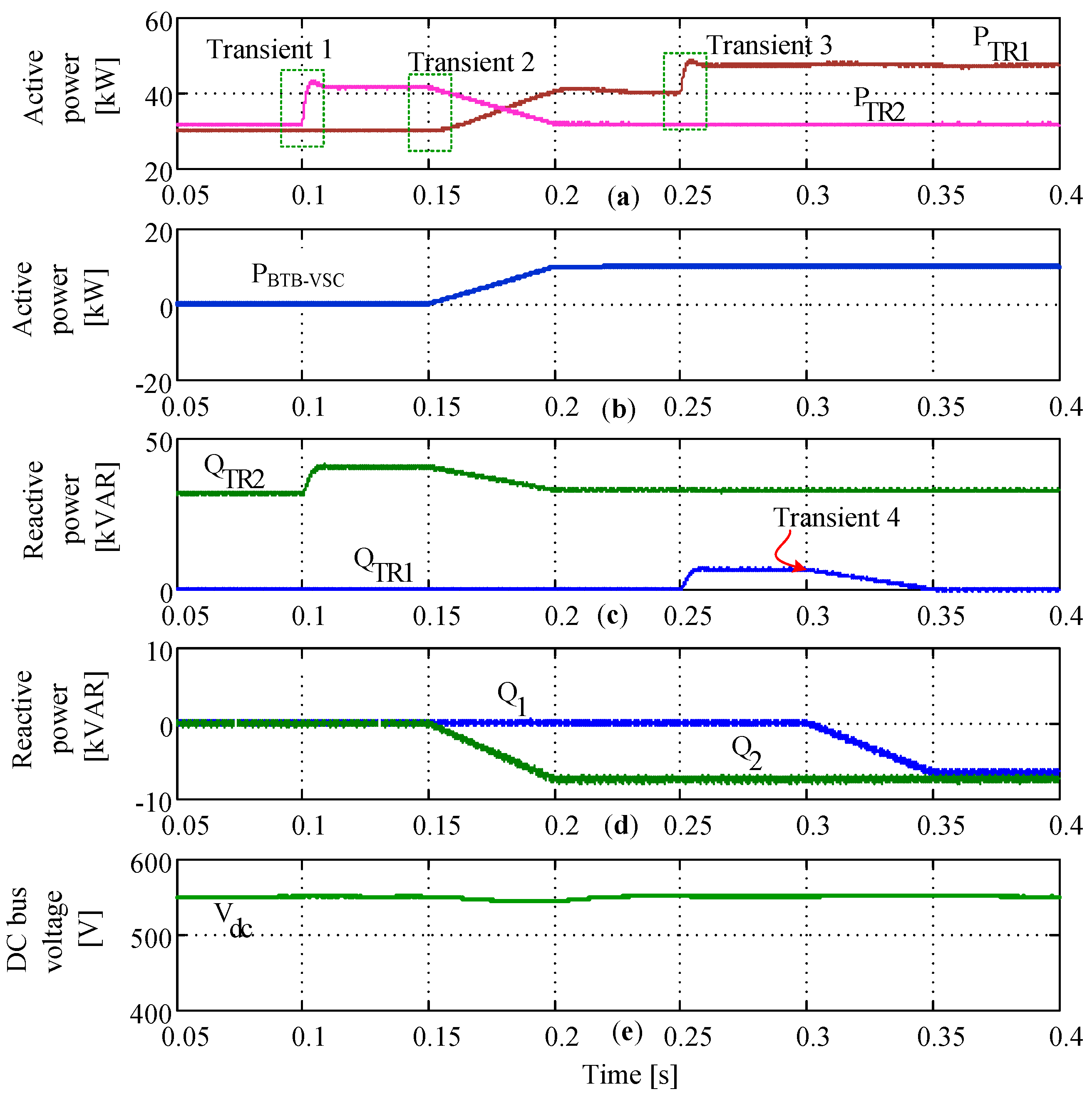
3.2.1. Case 8: Active Power Regulation and Reactive Power Compensation

The system starts with ZL11 connected to Fd1, as shown in Figure 1. ZL11 is rated at 30 kVA with unity power factor. This load corresponds to 60% of the capacity of Fd1. On the other side, ZL21 is connected to Fd2 and is rated at 45 kVA with a 0.7 lagging power factor. With this load, Fd2 is working at 90% of the rated capacity. The BTB-VSC is disconnected; therefore, switches CB1 and CB2 are open. At t = 0.1 s, ZL22 set at 12.5 kVA with a 0.8 lagging power factor is connected; with this load Fd2 operates at 25% above its rated capacity. Therefore, the BTB-VSC is activated at t = 0.15 s to relieve load from Fd2; for this, the BTB-VSC transfers 10 kW from Fd2 to Fd1 by applying a power-ramp condition. It is also used to compensate −7.5 kVAR through VSC2. Results are displayed in Figure 7. Figure 7a,c shows active and reactive powers for TR1 and TR2. Figure 7b,d show the active and reactive powers supplied by the BTB-VSC. As observed, the active and reactive power for TR1 and TR2 changes when the BTB-VSC is controlled to provide the given conditions described for the case. The DC bus voltage is shown in Figure 7e; it remains stable and regulated, even during the load transients. A second load (ZL12) is connected to Fd1at t = 0.25 s, this load is rated at 10 kVA with a 0.75 lagging power factor. Besides, the BTB-VSC is controlled to deliver the reactive power supplied by TR1 at t = 0.3 s, compensating −6.6 kVAR through VSC1. The profile of the currents for the test is shown in Figure 8, as noticed, currents are stable and regulated. The performance of BTB-VSC for Case 8 is displayed in Figure 9.

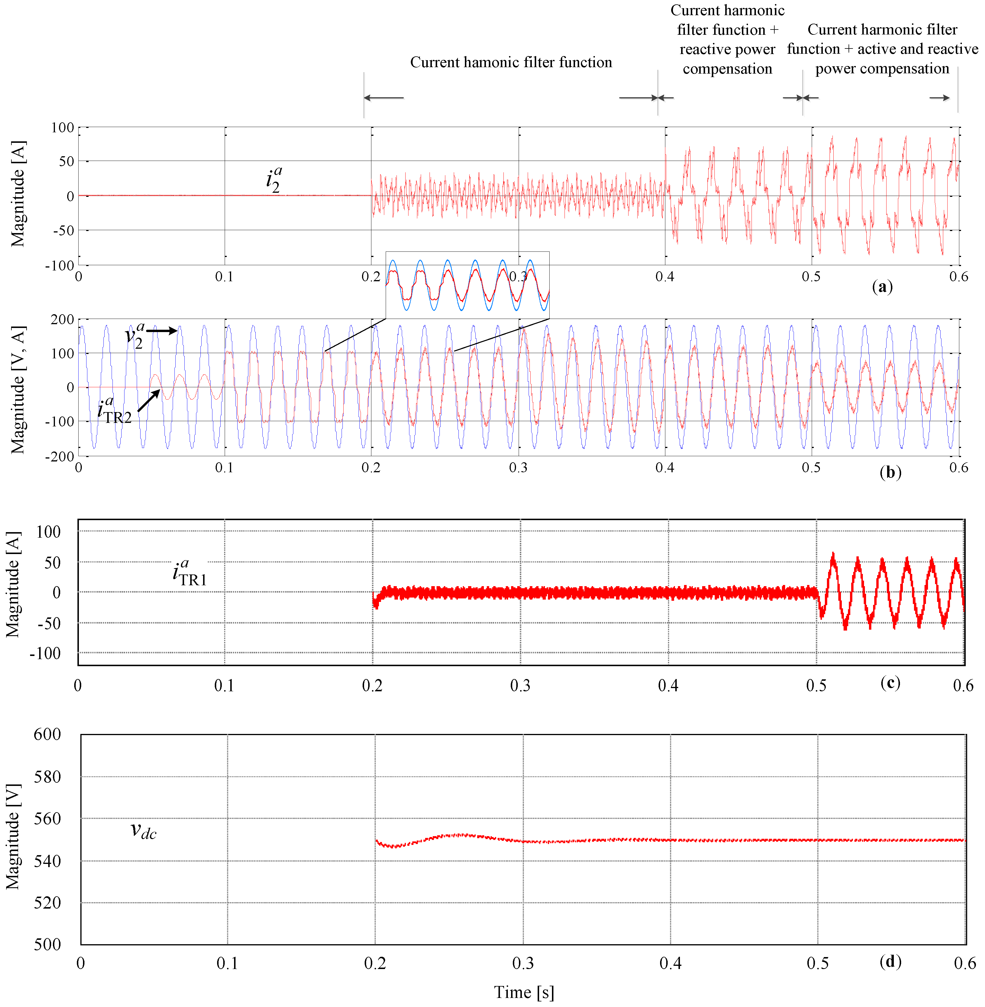
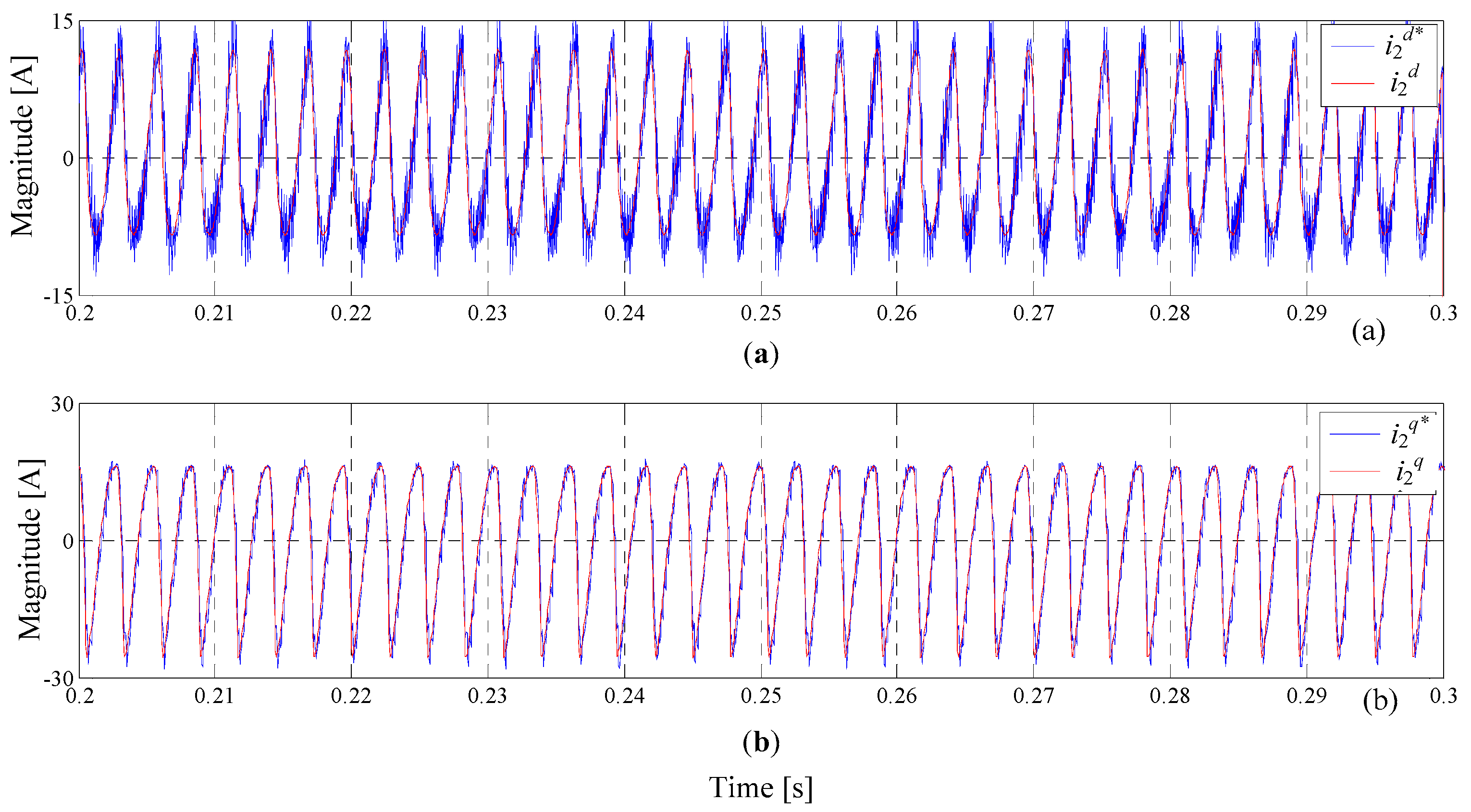
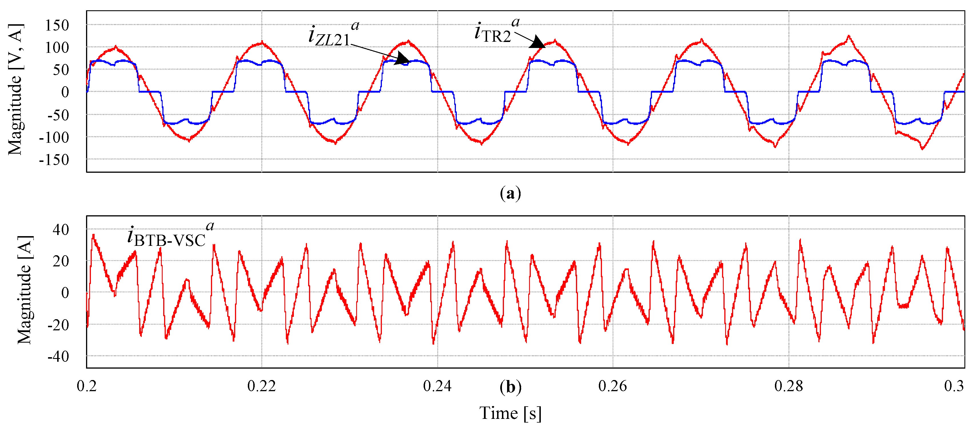
3.2.2. Active Filter Performance

To validate the performance of the BTB-VSC operating as a power flow controller and incorporating the active power filter functions, the conditions described below are considered. Moreover, in order to exemplify in the clearest way the operation of the BTB-VSC for current harmonic compensation, this function will be validated in terminals of PCC2. However, the compensation methodology is solved in the same way for PCC1. In this case, the test is developed by using three loads: a linear load rated at 10 kW, a 20 kVA nonlinear load and a 10 kVA inductive load with a 0.1 lagging power factor. The test is applied as described below and results are shown in Figure 10.
Initially, switches CB1 and CB2 are open and TR2 feeds the loads connected to Fd2. The first load is connected at t = 50 ms. The second load is switched on at t = 100 ms. The current evolution for phase a in terminals of TR2 in Figure 10b can be observed. At t = 200 ms the BTB-VSC is connected, the control algorithm determines the total current harmonic content at PCC2 and sets the required current reference to compensate it. Under this condition, the BTB-VSC is controlled to exclusively compensate current harmonics. The third load is connected at t = 300 ms. As observed in Figure 10b, the current lags voltage when the transient is applied. After this, the BTB-VSC is used to compensate the reactive power of the inductive load, the transient is applied at t = 0.4 s and, after the transient, the power factor at TR2 becomes unitary. Thus, from t = 0.2 s to t = 0.4 s, the BTB-VSC is simultaneously compensating the current harmonics content of nonlinear loads and the reactive power. The last condition is set at t = 0.5 s when the BTB-VSC is used to deliver 10 kW from TR2 to TR1. It can be observed that the current decreases in terminals of TR2. Figure 10d shows the DC bus voltage for the BTB-VSC: it remains stable and regulated at the desired operating point. In Figure 11, the dq control inputs and the references for BTB-VSC are displayed. Figure 12 shows the current waveforms for the nonlinear load, BTB-VSC and TR2 after compensation.
Table 4 shows the current harmonic components for the nonlinear load, the reference generated by the BTB-VSC and the given measured value at the PCC2. As observed, there is a linear relationship between the magnitude of the current harmonic component of the nonlinear load and the reference generated by the BTB-VSC. Using results given in Table 4, from the simulation results, the total harmonic distortion of the line current (THDc) at the PCC2 is reduced from 27.21% to 1.59%. This is a consequence of the correct generation of the harmonic compensation reference, and a good tracking characteristic of it, as shown in Figure 12. Furthermore, it can be noticed that the fundamental components of the load and TR2 are equal, and for the iBTB-VSC, it is zero. This is because the power grid supplies the power demanded by the load and also absorbs all the losses of the BTB converter through the regulation of the DC bus voltage.

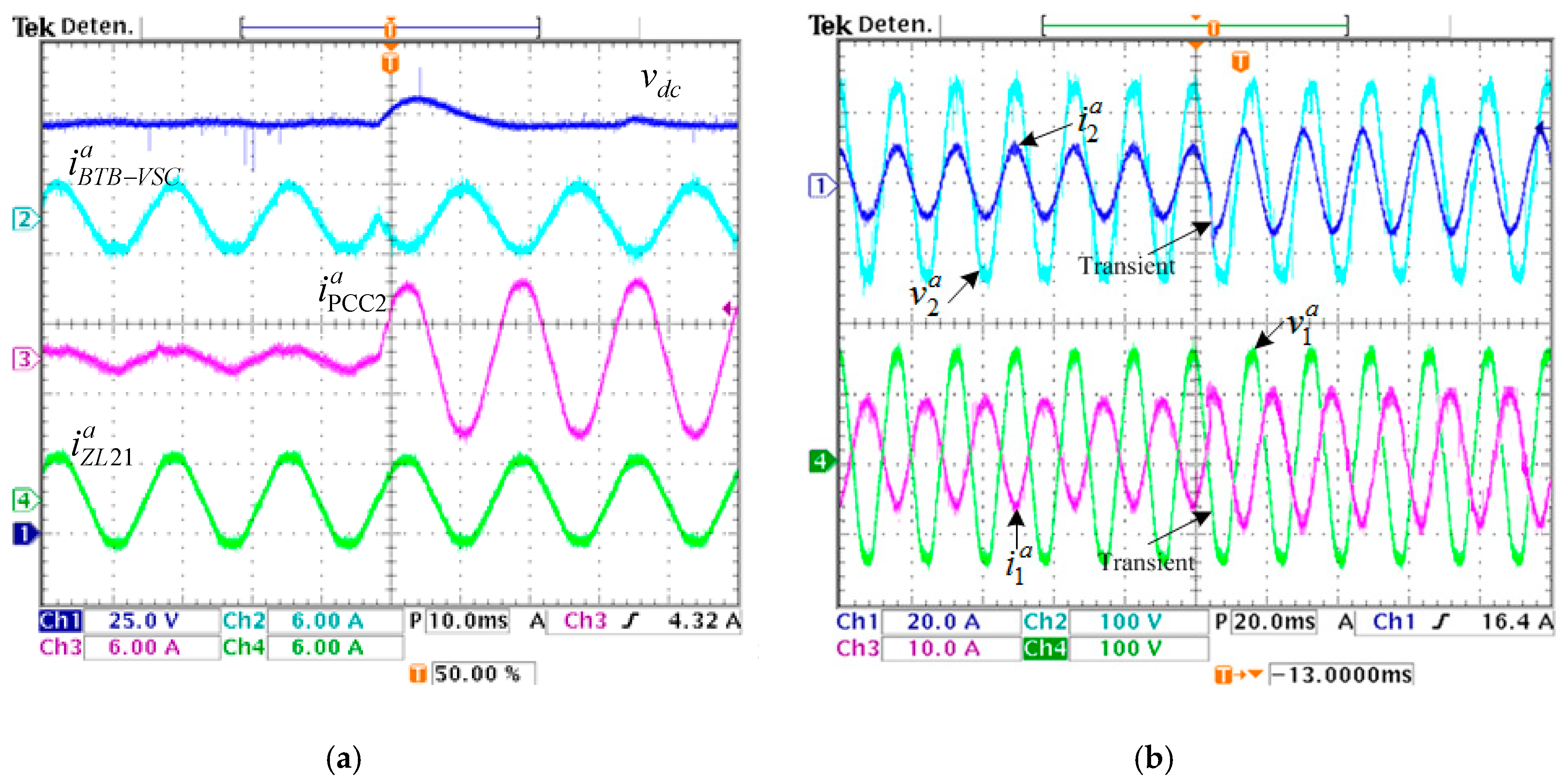
4. Experimental Results

A down-scale prototype 10:1 is constructed to verify the performance of the BTB-VSC. The experimental prototype parameters are given in Table 5. Experimental results are displayed from Figure 13, Figure 14, Figure 15, Figure 16 and Figure 17. For the results, P is associated to the active power, Q to the reactive power, and H to the harmonics content.
Figure 13 shows the results when the active power regulation is tested with the given conditions described below. TR2 is used to feed the load ZL21, 820 VA with unitary power factor. For the test, an active power step is applied to release load at terminals of TR2; the main idea is to use TR1 to supply 320 W to ZL21 and results are shown in Figure 13a,b. As observed, the DC bus voltage remains stable and regulated; a small voltage drop appears during the transient, however, it does not disturb the active power transferring.
To test the active power sharing, the following operating conditions are applied. TR2 supplies a base load (ZL21) of 820 VA with PF = 1 and, for load release, an active power step is applied. With the transient, 320 W are transferred from the PCC2 to the PCC1—results are shown in Figure 13a,b. It can be noticed that the DC bus voltage remains stable and regulated; there is a small variation during the power step but it produces no effect on the power supplied to the load.

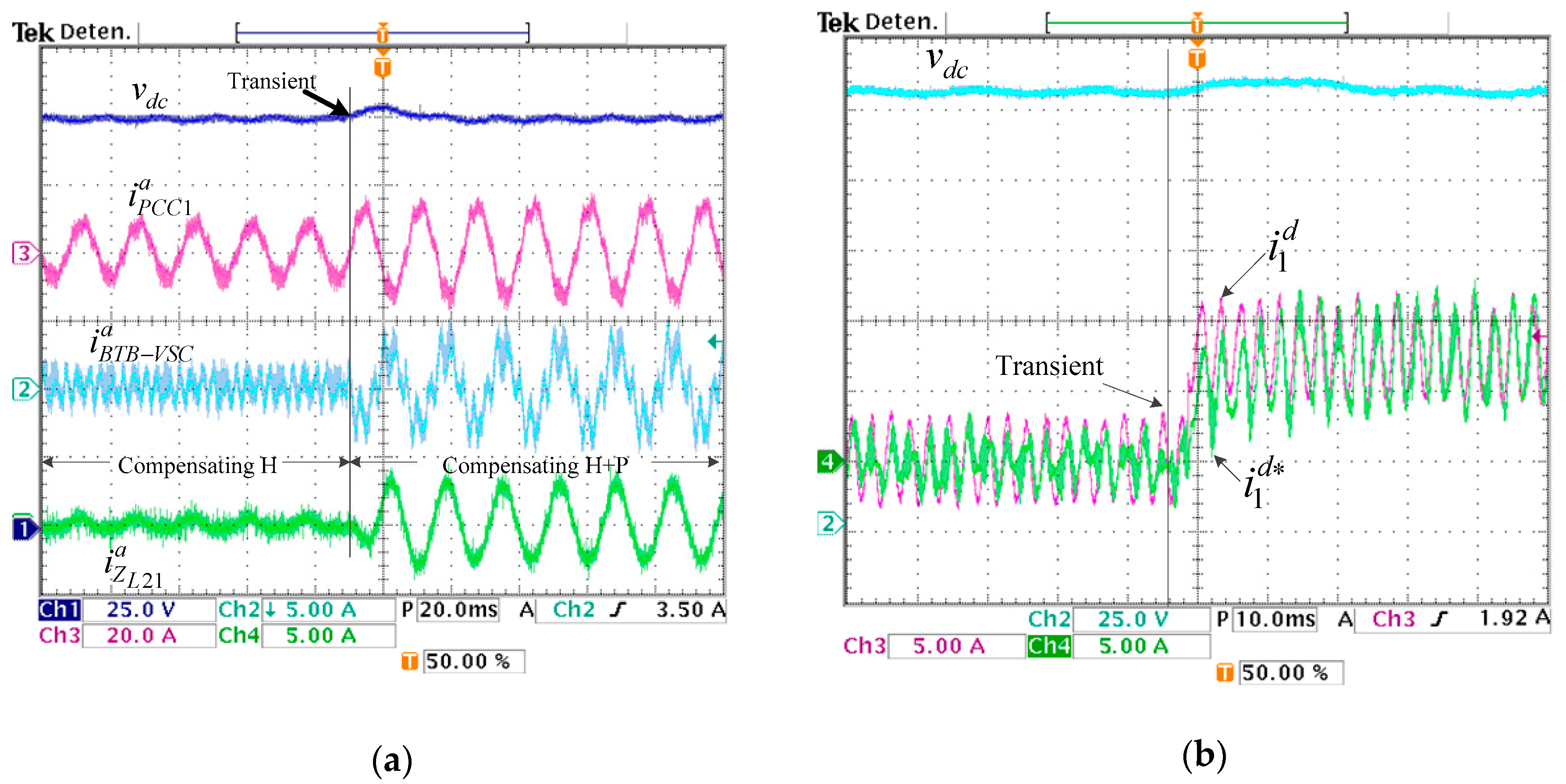
4.1. Active Power Regulation and Reactive Power Compensation

The capability of BTB-VSC to regulate and exchange active power between feeders was tested. Results shown in Figure 14a are obtained with following conditions: a 2 kW load (ZL21) is connected to PCC2 before the transient and the active power is supplied by TR1. When the transient is applied, the BTB-VSC is commanded to feed the load with TR2; therefore, the iBTB-VSC is reversed and the iPCC2 current increases. As observed, load current is not affected for the power reversal. The DC bus voltage overshoot is 4% of the nominal value and the settling time is set around 12 ms. For results given in Figure 14b, the BTB-VSC is controlled to transfer active power from TR1 to PCC2 and to compensate reactive power at terminals of VSC1 and VSC2. As shown, before the transient is applied, 2 kW are transferred to PCC2; then, the BTB-VSC is commanded to compensate 2.4 kVAR and −2.1 kVAR at terminals of PCC1 and PCC2, respectively.

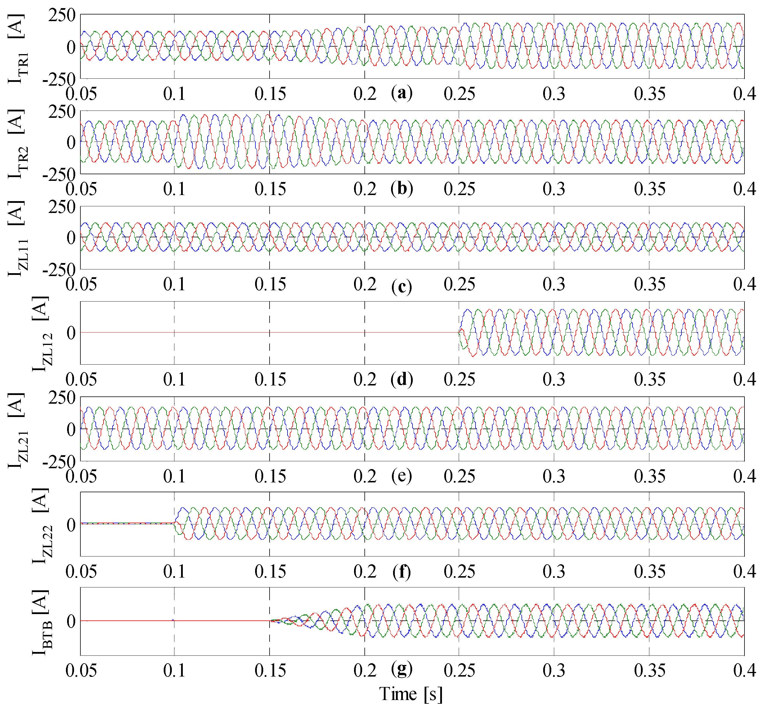
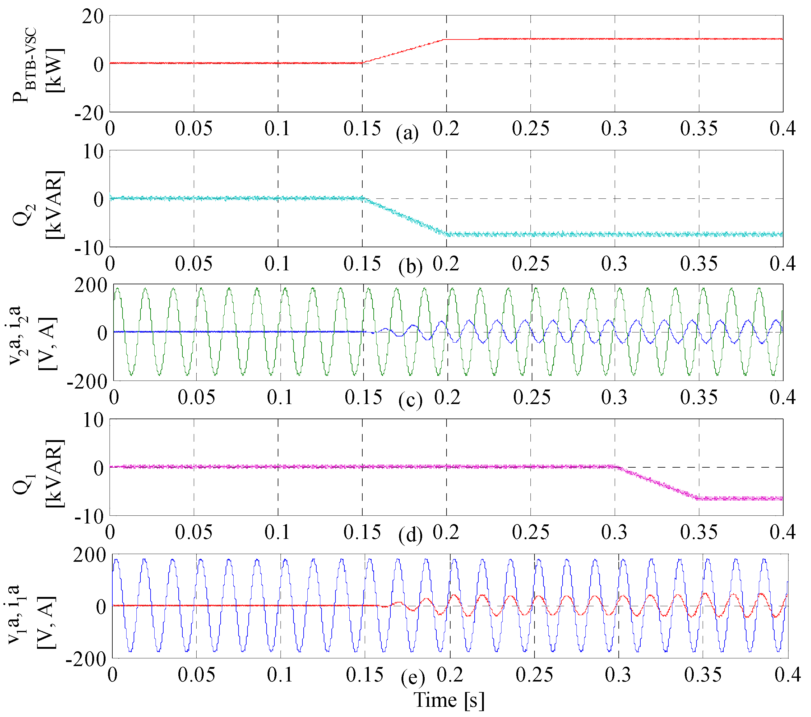
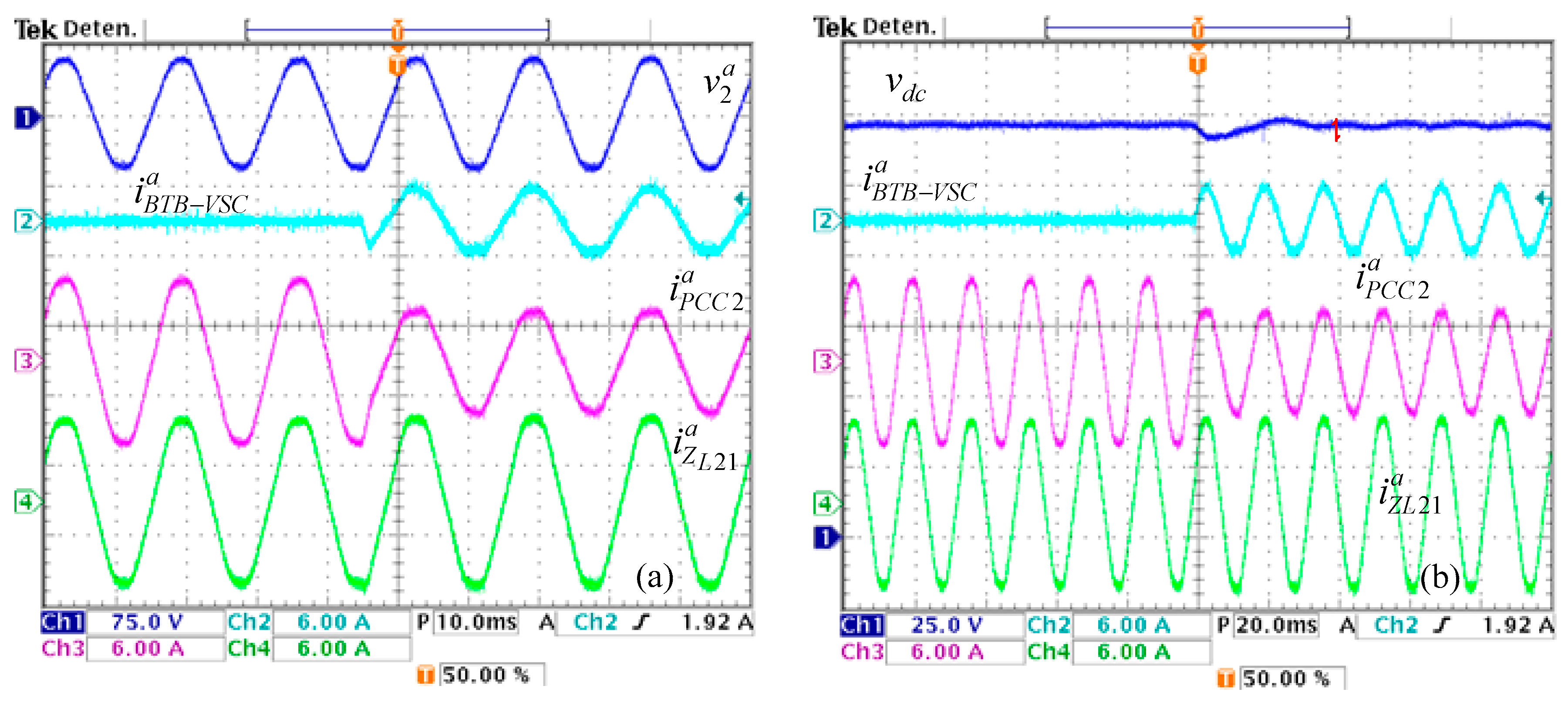
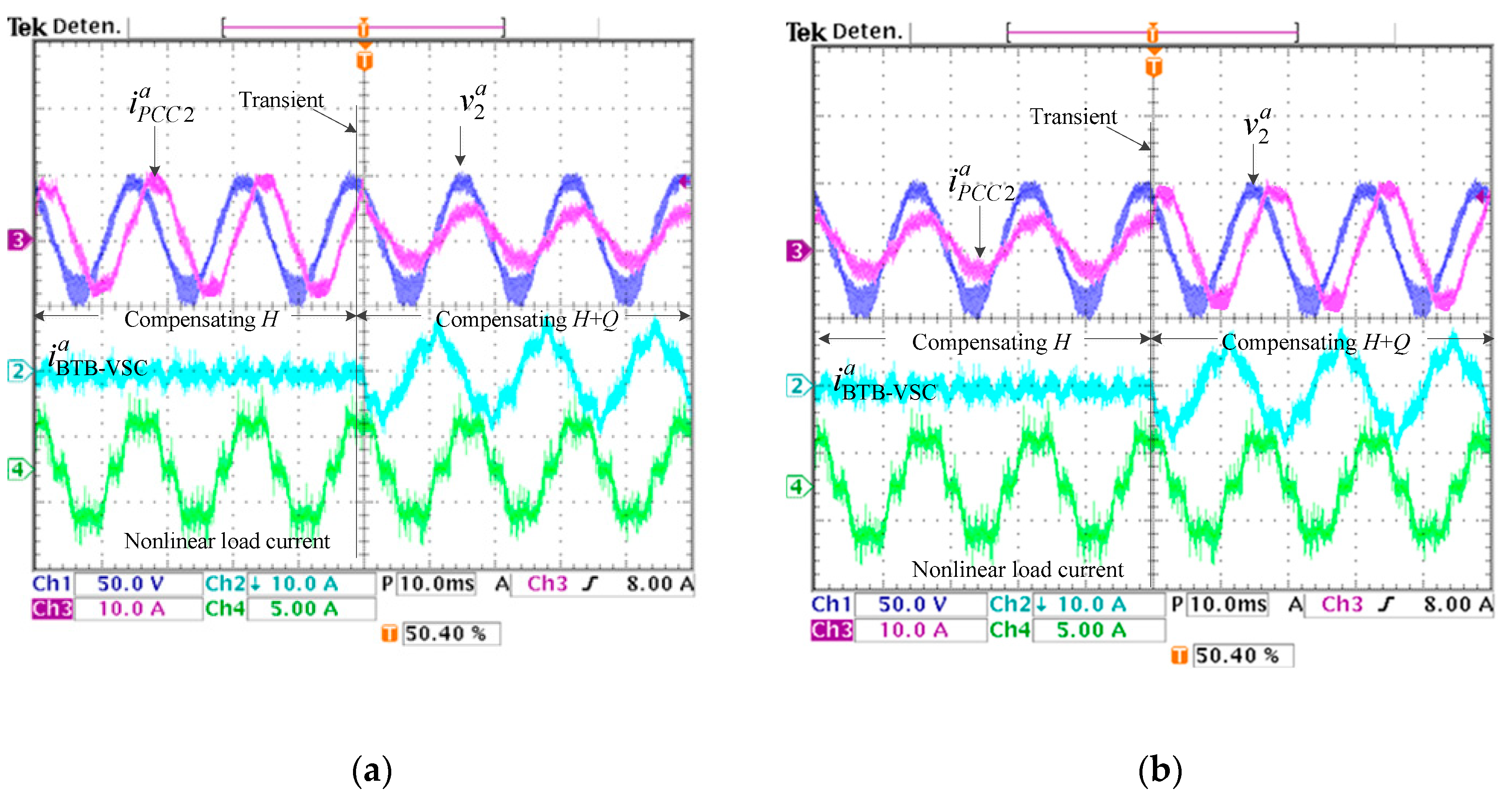
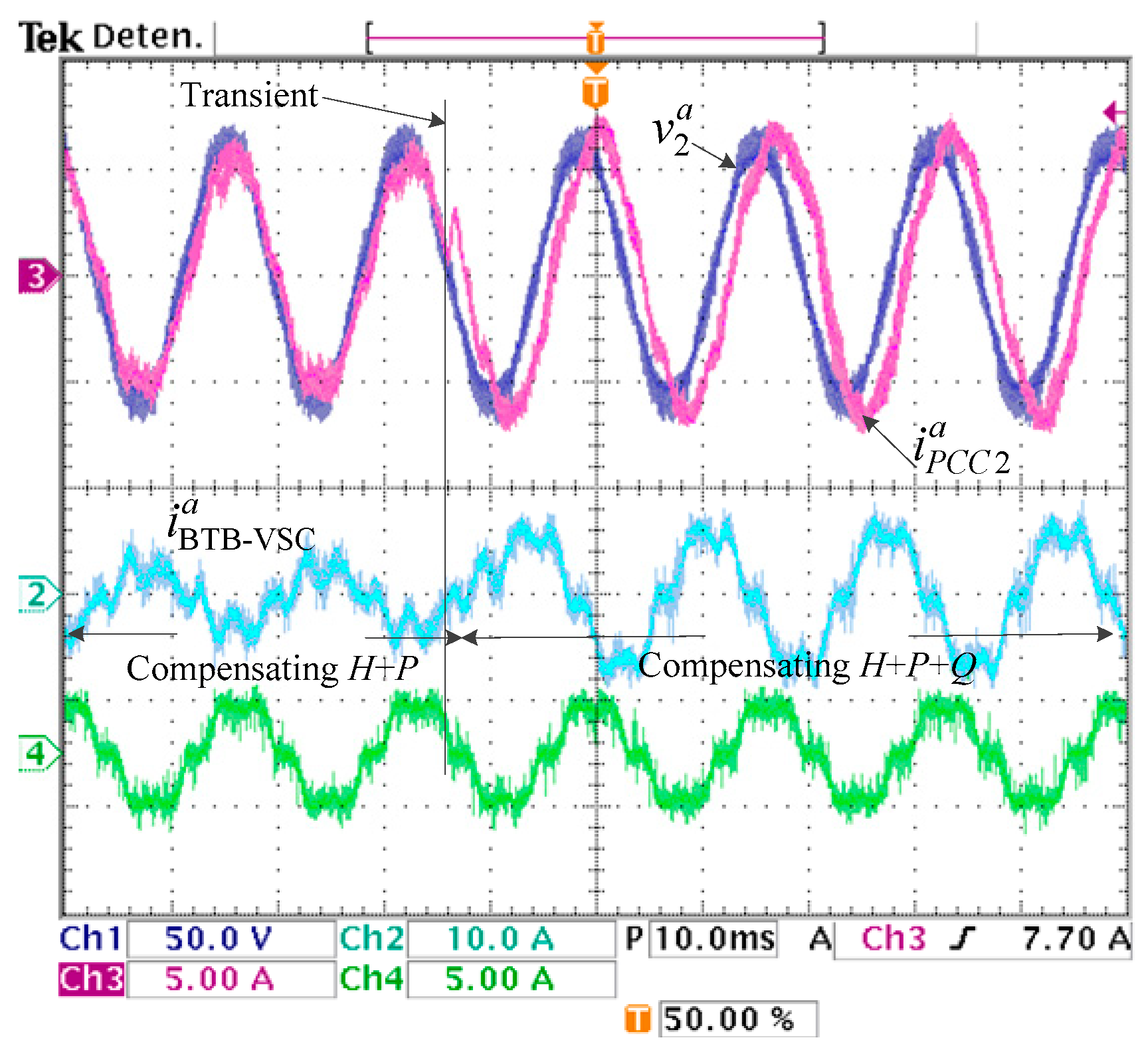
4.2. Active Power and Reactive Power Regulation and Current Harmonic Compensation

The BTB-VSC was tested compensating a 1 kVA nonlinear load connected to the PCC2. Results in steady state before and after compensation are shown in Figure 15a,b. If there are no loads connected to TR1 and there is only one nonlinear load connected to TR2, then, the current demanded by the nonlinear load iZL21 must be equal to the current measured at TR2. Although the BTB-VSC converter achieves a good performance during the tests, it does not reach the level of compensation that is obtained with simulation results, since, with the tests, the 5th and 7th current harmonics were reduced to 5.6% and 2.4% of the input current at fundamental frequency in comparison with the 0.68% and 0.64% obtained with simulation results. Considering these results, the THDc for simulations is set around 1.59%, whereas for experimental results it is 6.16%. The associated frequency spectrum after compensation, considering the 5th and 7th components, is shown in Figure 15c.
Figure 16 shows results for current harmonic filtering and active power regulation. For the test, a 500 W load (ZL11) and a 1 kVA nonlinear load (ZL12) are connected to PCC1. Results shown in Figure 16a are obtained as follows: initially, the BTB-VSC only compensates the current harmonics. Then, a 450 W load (ZL21) is connected to PCC2; at the same time, the BTB-VSC is ordered to supply the active power to ZL21 and the active power is obtained from TR1. After the transient, TR1 supplies 1.95 kW. It can be noticed the dynamic response is established in 24 ms. To complement the results, Figure 16b shows the dynamic response for i1d and i1d* components.
To validate the operation of BTB-VSC for current harmonic filtering and reactive power compensation, the system is tested with the following conditions: a 600 VAR capacitive load and a 1 kVA nonlinear load are connected to PCC2. Before the transient, the BTB-VSC only compensates the current harmonics of the nonlinear load; subsequently, a power step is applied and the BTB-VSC is controlled to supply the 600 VAR at the PCC2. Results are shown in Figure 17a and the opposite case is shown in Figure 17b. For this case, the BTB-VSC is activated to absorb the 600 VAR. The corresponding waveforms show the BTB-VSC can filter the current harmonics and also control the reactive power for leading and lagging power factors with a suitable and fast dynamic response. However, it is important to clarify that the capability to compensate reactive power is finite and it is limited and the boundaries fixed by the (P, Q) pair must take into account.
Results in Figure 18 presents waveforms plotted for active power regulation, reactive power compensation and current harmonic filtering. For the test, the BTB-VSC is used to compensate the current harmonics generated by a 1 kVA nonlinear load; it also must transfer 600 W from TR2 to PCC1 and compensate 600 VAR at PCC2. Before the transient, the current harmonics are compensated and the 600 W are delivered to PCC2 (compensating H+P). After the transient, the BTB-VSC supplies the 600 VAR (compensating H+P+Q), therefore, the rated power increases. In steady state, the total harmonic distortion of the line current at the PCC2 is reduced to 6.16%.

5. Discussion

In this paper, the performance of the three-phase BTB-VSC when it combines the power flow control and current harmonic compensation functions has been analyzed; a multifunctional control scheme based on PI controllers is proposed and realized. The BTB-VSC operation is classified considering eight modes for active power regulation and reactive power compensation and the current harmonic filtering is added to these modes. Experimental results validate that the BTB-VSC can perform the three tasks simultaneously and the APF contributes to minimizing the current harmonic distortion without affecting or reducing the power flow control with a suitable control law. The system inherits the independent operation of other combined technologies, and the advantages of hybrid power supply systems are proposed to solve these tasks. With the selected control strategy, the total current harmonic distortion was reduced from 27.21% to 6.16% for the experimental tests. The systematic research of an experimental set with extended functions is now under development. Further studies about the control and dynamics characteristics will be summarized in the next study.

Author Contributions

Formal analysis, J.A. and V.C.; Investigation, J.A. and A.A.; Methodology, J.A.; Project administration, A.A., J.G.-L. and S.C.; Software, J.G.-L.; Supervision, V.C.; Visualization, S.C.; Writing—original draft, J.A.; Writing—review & editing, V.C., A.A., J.G.-L. and S.C. All authors have read and agreed to the published version of the manuscript.

Funding

This research received no external funding.

Conflicts of Interest

The authors declare no conflict of interest.

References

  1. Siwakoti, Y.P.; Forouzesh, M.; Pham, N.H. Power Electronics Converters—An Overview. In Control of Power Electronic Converters and Systems, 1st ed.; Blaabjerg, F., Ed.; Academic Press: Cambridge, MA, USA, 2018; Volume 1, pp. 3–29. [Google Scholar] [CrossRef]
  2. Kolar, J.W.; Friedli, T.; Krismer, F.; Round, S.D. The essence of three-phase AC/AC converter systems. In Proceedings of the 2008 13th International Power Electronics and Motion Control Conference, Poznan, Poland, 1–3 September 2008; pp. 27–42. [Google Scholar] [CrossRef]
  3. Guidong, Z.; Zhong, L.; Bo, Z.; Wolfgang, H. Power electronics converters: Past, present and future. Renew. Sustain. Energy Rev. 2018, 81, 2028–2044. [Google Scholar] [CrossRef]
  4. Yaramasu, V.; Wu, B.; Sen, P.C.; Kouro, S.; Narimani, M. High-power wind energy conversion systems: State-of-the-art and emerging technologies. Proc. IEEE 2015, 103, 740–788. [Google Scholar] [CrossRef]
  5. Alcalá, J.; Cárdenas, V.; Espinoza, J.; Durán, M. Investigation on the limitation of the BTB-VSC converter to control the active and reactive power flow. Electr. Power Syst. Res. 2017, 143, 149–162. [Google Scholar] [CrossRef]
  6. Ni, K.; Hu, Y.; Lagos, D.T.; Chen, G.; Wang, Z.; Li, X. Highly Reliable Back-to-Back Power Converter without Redundant Bridge Arm for Doubly Fed Induction Generator-Based Wind Turbine. IEEE Trans. Ind. Appl. 2019, 55, 3024–3036. [Google Scholar] [CrossRef]
  7. Zeng, L.; Yao, W.; Zeng, Q.; Li, D.; Fang, J.; Ai, X.; Wen, J.; He, H. Design and real-time implementation of data-driven adaptive wide-area damping controller for back-to-back VSC-HVDC. Int. J. Electr. Power Energy Syst. 2019, 109, 558–574. [Google Scholar] [CrossRef]
  8. Spagnuolo, G.; Petrone, G.; Araujo, S.V.; Cecati, C.; Friis-Madsen, E.; Gubia, E.; Hissel, E.; Jasinski, M.; Knapp, W.; Liserre, M.; et al. Renewable Energy Operation and Conversion Schemes: A Summary of Discussions during the Seminar on Renewable Energy Systems. IEEE Ind. Electron. Mag. 2010, 4, 38–51. [Google Scholar] [CrossRef] [Green Version]
  9. Khorasani, P.G.; Joorabian, M.; Seifossadat, S.G. Smart grid realization with introducing unified power quality conditioner integrated with DC microgrid. Electr. Power Syst. Res. 2017, 151, 68–85. [Google Scholar] [CrossRef]
  10. Senthilkumar, A.; Raj, P.A. ANFIS and MRAS-PI controllers based adaptive-UPQC for power quality enhancement application. Electr. Power Syst. Res. 2015, 126, 1–11. [Google Scholar] [CrossRef]
  11. Lee, K.B.; Shin, H.U.; Bak, Y. Basic Control of AC Motor Drives. In Control of Power Electronic Converters and Systems; Blaagjerg, F., Ed.; Academic Press: Cambridge, MA, USA, 2018; Volume 1, pp. 301–329. [Google Scholar] [CrossRef]
  12. Park, H.S.; Heo, H.J.; Choi, B.S.; Kim, K.C.; Kim, J.M. Speed control for turbine-generator of ORC power generation system and experimental implementation. Energies 2019, 12, 200. [Google Scholar] [CrossRef] [Green Version]
  13. Hertem, D.V.; Gomis-Bellmunt, O.; Liang, J. HVDC technology overview. In HVDC Grids: For Offshore and Supergrid of the Future; Academic Press: Cambridge, MA, USA, 2016; pp. 47–76. [Google Scholar]
  14. Nguyen, Q.; Todeschini, G.; Santoso, S. Power Flow in a Multi-Frequency HVac and HVdc System: Formulation, Solution, and Validation. IEEE Trans. Power Syst. 2019, 34, 2487–2497. [Google Scholar] [CrossRef]
  15. Zeng, L.; Li, D.; Yao, W.; Sun, J.; Wen, J. Dual-loop SFC scheme for BTB-VSC-HVDC interconnecting asynchronous AC grids. J. Eng. 2019, 3, 1020–1026. [Google Scholar] [CrossRef]
  16. Cai, D.; Zhou, K.; Wang, W.; Liu, H.; Cao, K.; Wang, Y. Influence of back-to-back VSC-HVDC project on the operation characteristics of Hubei power grid. J. Eng. 2017, 801–805. [Google Scholar] [CrossRef]
  17. Abdelsalam, I.; Adam, G.P.; Williams, B.W. Current source back-to-back converter for wind energy conversion systems. IET Renew. Power Gener. 2016, 10, 1552–1561. [Google Scholar] [CrossRef] [Green Version]
  18. Nami, A.; Rodríguez Amenedo, J.L.; Arnaltes Gómez, S.; Cardiel Álvarez, M.A. Active Power Filtering Embedded in the Frequency Control of on Offshore Wind Farm Connected to a Diode-Rectifier-Based HVDC Link. Energies 2018, 11, 2718. [Google Scholar] [CrossRef] [Green Version]
  19. Agheb, E.; Holtsmark, N.; Hoidalen, H.K.; Molinas, M. High frequency wind energy conversion system for offshore DC collection grid—Part I: Comparative loss evaluation. Sustain. Energy Grids Netw. 2016, 5, 167–176. [Google Scholar] [CrossRef]
  20. López, I.; Andreu, J.; Ceballos, S.; de Alegría, I.M.; Kortabarria, I. Review of wave energy technologies and the necessary power-equipment. Renew. Sustain. Energy Rev. 2013, 25, 413–434. [Google Scholar] [CrossRef]
  21. Kumar, D.; Zare, F. A Comprehensive Review of Maritime Microgrids: System Architectures, Energy Efficiency, Power Quality, and Regulations. IEEE Access 2019, 7, 67249–67277. [Google Scholar] [CrossRef]
  22. Müller, N.; Kouro, S.; Malinowski, M.; Rojas, C.A.; Jasinski, M.; Estay, G. Medium-Voltage Power Converter Interface for Multigenerator Marine Energy Conversion Systems. IEEE Trans. Ind. Electron. 2017, 64, 1061–1070. [Google Scholar] [CrossRef]
  23. Singh, B.; Saha, R.; Chandra, A.; Al-Haddad, K. Static synchronous compensators (STATCOM): A review. IET Power Electron. 2009, 2, 297–324. [Google Scholar] [CrossRef]
  24. Mete, A.; Çağatay, K. Power flow modeling of Back-to-Back STATCOM: Comprehensive simulation studies including PV curves and PQ circles. Ain Shams Eng. J. 2017, 8, 431–443. [Google Scholar] [CrossRef] [Green Version]
  25. Baimel, D. Implementation of DQ0 control methods in high power electronics devices for renewable energy sources, energy storage and FACTS. Sustain. Energy Grids Netw. 2019, 18. [Google Scholar] [CrossRef]
  26. Shu, Z.; Xie, S.; Li, Q. Single-Phase Back-To-Back Converter for Active Power Balancing, Reactive Power Compensation, and Harmonic Filtering in Traction Power System. IEEE Trans. Power Electron. 2011, 26, 334–343. [Google Scholar] [CrossRef]
  27. Naidu, N.K.S.; Singh, B. Doubly Fed Induction Generator for Wind Energy Conversion Systems with Integrated Active Filter Capabilities. IEEE Trans. Ind. Inform. 2015, 11, 923–933. [Google Scholar] [CrossRef]
  28. 519-2014—IEEE Recommended Practice and Requirements for Harmonic Control in Electric Power Systems—Redline. 2014. Available online: http://ieeexplore.ieee.org/stamp/stamp.jsp?tp=&arnumber=7047985&isnumber=7047984 (accessed on 13 February 2020).
  29. Zhang, Z.; Xie, B.; Hu, S.; Li, Y.; Luo, L.; Rehtanz, C.; Krause, O. Reactive Power Compensation and Negative-Sequence Current Suppression System for Electrical Railways with YNvd-Connected Balance Transformer—Part I: Theoretical Analysis. IEEE Trans. Power Electron. 2018, 33, 272–282. [Google Scholar] [CrossRef]
  30. Zhengyou, H.; Zheng, Z.; Haitao, H. Power quality in high-speed railway systems. Int. J. Rail Transp. 2016, 4, 71–97. [Google Scholar] [CrossRef] [Green Version]
  31. Kissling, S.; Talon, E.; Biya-Motto, F.; Essimbi, B.; Carpita, M. Control of a Three-Phase to Single Phase Back-to-Back Converter for Electrical Resistance Seam Welding Systems. Energies 2017, 10, 133. [Google Scholar] [CrossRef] [Green Version]
  32. Zargari, N.R.; Joos, G. Performance investigation of a current-controlled voltage-regulated PWM rectifier in rotating and stationary frames. IEEE Trans. Ind. Electron. 1995, 42, 396–401. [Google Scholar] [CrossRef]
  33. Abdelhakim, A.; Mattavelli, P.; Boscaino, V.; Lullo, G. Decoupled Control Scheme of Grid-Connected Split-Source Inverters. IEEE Trans. Ind. Electron. 2017, 64, 6202–6211. [Google Scholar] [CrossRef]
  34. Moran, L.; Dixón, J.; Torres, M. 41-Active Power Filters. In Power Electronics Handbook, 4th ed.; Rashid, M.H., Ed.; Butterworth-Heinemann Elsevier Ltd.: Oxford, UK, 2018; pp. 1341–1379. [Google Scholar] [CrossRef]
  35. Akagi, H.; Kanazawa, Y.; Nabae, A. Instantaneous Reactive Power Compensators Comprising Switching Devices without Energy Storage Components. IEEE Trans. Ind. Appl. 1984, IA-20, 625–630. [Google Scholar] [CrossRef]
  36. Khorramabadi, S.S.; Bakhshai, A. Critic-Based Self-Tuning PI Structure for Active and Reactive Power Control of VSCs in Microgrid Systems. IEEE Trans. Smart Grid 2015, 6, 92–103. [Google Scholar] [CrossRef]
  37. Alcala, J.; Cardenas, V.; Miranda, H.; Perez-Ramirez, J.; Charre, S. A three-phase back to back converter for reactive power compensation, current harmonic filtering and active power compensation. In Proceedings of the Energy Conversion Congress and Exposition (ECCE), Denver, CO, USA, 15–19 September 2013; pp. 2371–2377. [Google Scholar] [CrossRef]
  38. Yang, W.; Song, Q.; Liu, W. Decoupled Control of Modular Multilevel Converter Based on Intermediate Controllable Voltages. IEEE Trans. Ind. Electron. 2016, 63, 4695–4706. [Google Scholar] [CrossRef]
  39. Parvez, M.; Elias, M.F.M.; Rahim, N.A.; Osman, N. Current control techniques for three-phase grid interconnection of renewable power generation systems: A review. Sol. Energy 2016, 135, 29–42. [Google Scholar] [CrossRef]
  40. Meng, X.; Liu, J.; Liu, Z. A Generalized Droop Control for Grid-Supporting Inverter Based on Comparison between Traditional Droop Control and Virtual Synchronous Generator Control. IEEE Trans. Power Electron. 2019, 34, 5416–5438. [Google Scholar] [CrossRef]
  41. Li, S.; Haskew, T.A.; Swatloski, R.P.; Gathings, W. Optimal and Direct-Current Vector Control of Direct-Driven PMSG Wind Turbines. IEEE Trans. Power Electron. 2012, 27, 2325–2337. [Google Scholar] [CrossRef]
  42. Ramezani, M.; Li, S.; Sun, Y. Combining droop and direct current vector control for control of parallel inverters in microgrid. IET Renew. Power Gener. 2017, 11, 107–114. [Google Scholar] [CrossRef]
Figure 1. Simplified configuration of the proposed system.
Energies 13 00831 g001
Figure 2. Block diagram representation for the three-phase back-to-back voltage source converter (BTB-VSC).
Energies 13 00831 g002
Figure 3. dq waveforms for nonlinear signals.
Energies 13 00831 g003
Figure 4. General block diagram for the BTB-VSC.
Energies 13 00831 g004
Figure 5. Block diagram to obtain the harmonic current reference waveforms.
Energies 13 00831 g005
Figure 6. Control block diagram for VSC2.
Energies 13 00831 g006
Figure 7. Case 8. (a) Active power for transformers TR1 and TR2. (b) Active power regulated with the BTB-VSC. (c) Reactive power for TR1 and TR2. (d) Reactive power compensated by the BTB-VSC. (e) direct current (DC) bus voltage.
Energies 13 00831 g007
Figure 8. abc currents for Case 8. (a) TR1. (b) TR2. (c) ZL11. (d) ZL12. (e) ZL21. (f) ZL22. (g) BTB-VSC.
Energies 13 00831 g008
Figure 9. Performance of the BTB-VSC for Case 8. (a) Active power flowing between feeders. (b) Reactive power compensated by VSC2. (c) Voltage and current at terminals of VSC2. (d) Reactive power compensated by VSC1. (e) Voltage and current at terminals of VSC1.
Energies 13 00831 g009
Figure 10. Before and after compensation for the BTB-VSC. (a) Current for phase a injected to the PCC2 by the BTB-VSC. (b) Voltage and current for phase a at the PCC2. (c) Current for phase a measured at the PCC1. (d) DC bus voltage.
Energies 13 00831 g010
Figure 11. dq control components for the BTB-VSC when it compensates active and reactive power and the current harmonics: (a) i2d (blue) and its reference i2d* (red). (b) i2q (red) and its reference i2q* (blue).
Energies 13 00831 g011
Figure 12. BTB-VSC performances when it compensates active and reactive power and the current harmonics: (a) current waveforms for the load, iZL21a (blue) and for TR2, iTR2a (red) after compensation (red). (b) Current waveform generated by BTB-VSC.
Energies 13 00831 g012
Figure 13. Test results for active power regulation: (a) Ch1, voltage measured at the PCC2; Ch2, current injected with the BTB-VSC at the PCC2; Ch3, current measured at the PCC2; Ch4, current for the load ZL21. Vertical sensitivities: Ch1, 75V/div; Ch2-Ch4, 6A/div. Horizontal sensitivity: 10 ms/div. (b) Ch1, DC bus voltage; Ch2, current injected with the BTB-VSC at the PCC2; Ch3, current measured at the PCC2; Ch4, current for the load ZL21. Vertical sensitivities: Ch1, 25V/div; Ch2-Ch4, 6A/div. Horizontal sensitivity: 20 ms/div.
Energies 13 00831 g013
Figure 14. Test results: (a) Active power flow reversal. Ch1, DC bus voltage; Ch2, current injected with the BTB-VSC at the PCC2; Ch3, Current measured at the PCC2; Ch4, current for the load ZL21. Vertical sensitivities: Ch1, 25 V/div; Ch2–Ch4, 6 A/div. Horizontal sensitivity: 10 ms/div. (b) Active power regulation and reactive power compensation. Ch1, current measured at the PCC2; Ch2, voltage measured at the PCC2; Ch3, current measured at the PCC1; Ch4, voltage measured at the PCC1. Vertical sensitivities: Ch1, 20 A/div; Ch3, 10A/div; Ch2 and Ch4, 100 V/div. Horizontal sensitivity: 20 ms/div.
Energies 13 00831 g014
Figure 15. Test results for current harmonic compensation: (a) Before compensation. Ch1, voltage measured at the PCC2; Ch2, current injected with the BTB-VSC at the PCC2; Ch3, current measured at the PCC2; Ch4, current for the load ZL21. Vertical sensitivities: Ch1, 50 V/div; Ch2, 10 A/div, Ch3 and Ch4, 5 A/div. Horizontal sensitivity: 10 ms/div. (b) After compensation. Ch1, voltage measured at the PCC2; Ch2, current injected with the BTB-VSC at the PCC2; Ch3, current measured at the PCC2; Ch4, current for the load ZL21. Vertical sensitivities: Ch1, 50 V/div; Ch2-Ch4, 5 A/div. Horizontal sensitivity, 10 ms/div. (c) Current for the nonlinear load and the associated frequency spectrum. Ch3, current measured at the PCC2; Ch4, current for the load ZL21. Mat., frequency spectrum. Vertical sensitivities: Ch3 and Ch4, 5 A/div. Mat., 1 A/div. Horizontal sensitivity: Ch3 and Ch4, 10 ms/div; Mat., 62 Hz/div.
Energies 13 00831 g015
Figure 16. Test results for current harmonic and active power regulation: (a) Ch1, DC bus voltage; Ch2, current injected with the BTB-VSC; Ch3, current measured at the PCC1; Ch4, current for the load ZL21. Vertical sensitivities: Ch1, 25 V/div; Ch3, 20 A/div, Ch2 and Ch4, 5 A/div. Horizontal sensitivity: 20 ms/div. (b) Ch2, DC bus voltage; Ch3 and Ch4, d and q current waveforms. Vertical sensitivities: Ch2, 25 V/div, Ch3 and Ch5 5, A/div. Horizontal sensitivity: 10 ms/div.
Energies 13 00831 g016
Figure 17. Test results for current harmonic and reactive power compensation: (a) Leading power factor and (b) Lagging power factor. Ch1, voltage measured at the PCC2; Ch2, current injected with the BTB-VSC; Ch3, current measured at the PCC2; Ch4, Current of the nonlinear load. Vertical sensitivities: Ch1, 50 V/div; Ch2 and Ch3, 10 A/div; Ch4, 5 A/div. Horizontal sensitivity: 10 ms/div.
Energies 13 00831 g017
Figure 18. Test results for compensation of current harmonics, active and reactive powers. Ch1, voltage measured at the PCC2; Ch2, current injected with the BTB-VSC; Ch3, current measured at the PCC; Ch4, nonlinear current. Vertical sensitivities: Ch1, 50V/div; Ch2, 10A/div; Ch3 and Ch4, 5 A/div. Horizontal sensitivity: 10 ms/div.
Energies 13 00831 g018
Table 1. PQ operating modes for the BTB-VSC 1.
CasePQ1Q2
1000
2001
3010
4011
5100
6101
7110
8111
1 States 1 and 0 represent the ON and OFF states, respectively.
Table 2. Power system parameters.
Grid and BTB-VSC Parameters
Grid Voltage220 VrmsVdc550 V
ω1,2377 rad/sSBTB-VSC30 kVA
L14.1 mHfsw4.86 kHz
L25.3 mHCdc4700 µF
R130 mΩ
R230 mΩ
Table 3. Proportional and integral (PI) controller’s parameters for outer loops.
GainController
vdcQ1P2Q2
kp0.5140.0100.0100.010
ki102−2.93753.6971−2.9375
Table 4. Current harmonic components: simulation results of the considered case.
Harmonic OrderLoad [Arms]BTB-VSC [Arms]TR2 [Arms]
hMagnitude%MagnitudeMagnitude%
152.021000.0152.01100
511.7522.5811.390.350.68
75.5410.645.200.330.64
114.248.143.910.330.63
132.655.102.330.330.63
172.164.151.810.350.67
191.462.811.120.340.65
THDc 27.21 1.59
Table 5. Prototype parameters for BTB-VSC.
Grid and BTB-VSC Parameters
V1abc127–50 Vrms
V2abc12–42 Vrms
STR1, STR23 kVA
ω1,2377 rad/s
L14.1 mH
L25.3 mH
R1284 mΩ
R2330 mΩ
Vdc150 V
SBTB-VSC3 kVA
fsw4.81 kHz
Cdc1050 µF

