Abstract
Lithium iron orthosilicate (LFS) cathode can be prepared via the polyol-assisted ball milling method with the incorporation of carbon derived from eggshell membrane (ESM) for improving inherent poor electronic conduction. The powder X-ray diffraction (XRD) pattern confirmed the diffraction peaks without any presence of further impure phase. Overall, 9 wt.% of carbon was loaded on the LFS, which was identified using thermogravimetric analysis. The nature of carbon was described using parameters such as monolayer, and average surface area was 53.5 and 24 m2 g−1 with the aid of Langmuir and Brunauer–Emmett–Teller (BET) surface area respectively. The binding energy was observed at 285.66 eV for C–N owing to the nitrogen content in eggshell membrane, which provides more charge carriers for conduction. Transmission electron microscopy (TEM) images clearly show the carbon coating on the LFS, the porous nature of carbon, and the atom arrangements. From the cyclic voltammetry (CV) curve, the ratio of the anodic to the cathodic peak current was calculated as 1.03, which reveals that the materials possess good reversibility. Due to the reversibility of the redox mechanism, the material exhibits discharge specific capacity of 194 mAh g−1 for the first cycle, with capacity retention and an average coulombic efficiency of 94.7% and 98.5% up to 50 cycles.
1. Introduction
Employing clean and renewable energy is a challenging one for researchers trying to reduce the dependency on fossil fuels. Several attempts have been made to consume renewable energy without interruption. It is a key issue because of the intermittence and unpredictable nature of renewable/clean energy [1,2,3,4]. Storage devices hold a perfect place to rectify the above-mentioned issue and provide a constant energy supply whenever it needs. A progressive investigation has been implemented for commercializing a high-energy storage battery with nominal price by selecting abundant raw material [5,6,7]. Exclusively, Li-ion batteries are one the most promising solutions owing to their outstanding electrochemical performance [8]. Li-ion batteries comprise a separator [9], electrolyte [10], anode [11], and cathode [12]. Within this, the electrochemical performance and capacity of the battery are highly dependent on the choice of cathode materials. Several commercialized cathode materials used for lithium ion batteries often mentioned are LiCoO2 [13], LiMn2O4 [14], LiFePO4 [15], etc. LiFePO4 exhibits better performance with features like non-toxic and abundant raw material, potential stability, safety etc., although its specific capacity need to improvise [16]. After long research, Lithium iron silicate (Li2FeSiO4) arrived in 2005 with the theoretical capacity twice the time of LiFePO4. It is also a safer and environmentally benign cathode material for energy storage applications [17]. Physical and electrochemical factors such as structural imperfection, ion diffusion, and low electronic conduction inhibit the utilization of theoretical capacity [18]. The inherent poor electronic conduction and ionic diffusion must be resolved by adopting some approaches such as particle size reduction [19], metal doping [20], and carbon coating on the surface of LFS [21]. The reduced particle size of LFS paved a way to shorten the Li+ diffusion path. Hence, nanosized materials are still emerging in Li-ion batteries [22]. Cation doping is an effective strategy for widening the Li+ diffusion channel and increases the output voltage of LFS-based Li-ion batteries [23]. Carbon coating is another effective approach to improve the electronic conductivity of cathodes made from Li2FeSiO4. Not only does it display excellent conduction behavior, carbon established an ideal matrix for cathode LFS which is due to the high dispersal over the surface. Besides, carbon coating prevents the decomposition of the electrolyte and integrates the particles within the volume. In this LFS, different carbon sources have been used to enhance the conductivity of LFS [24]. In the sol-gel method, sorbitanlaurat was used as carbon source by Qu et al. [25] and obtained the specific discharge capacity of 187 mAh g−1 at 0.1 C. Yen et al. [26] reveals that carbon derived from L-ascorbic acid on LFS exhibits the capacity of 137 mAh g−1 at slow rate (C/16). The biological material methylcellulose is used as a carbon source and dispersing agent to enable the homogeneity of the particle and to control the crystal size [27]. The carbon composite is from Indian ink, which has good electronic conduction, and leads to good electrochemical performance with a discharge capacity of 197 mAh g−1 at 0.1 C [28]. Carbon covered over the surface, when the LFS is pyrolysis with 20 wt.% of starch and polymer backbone PVA delivers a discharge capacity of 135 mAh g−1 at slow rate (C/16) [29]. The porous nature of carbon paved fast ionic transport, a highly accessible active area for Li-ion insertion [30]. According to these different carbon sources used as composite with LFS, the performance of the LFS cathode in strongly increased by implement the carbon coating technique.
Here an effort has been made to drive carbon from eggshell membranes, which is coated over the Li2FeSiO4 via the ball miller assisted polyol method. The prodigious consumption of hen eggs results in higher amounts of egg waste. The major problem associated with disposal of these eggshell membranes is faced by bakery and poultry authorities. Instead of treating these eggshells with hazardous chemicals for recycling, we can instead use carbon from eggshell membranes as a composite coating on Li2FeSiO4. Then the structural, morphological and electrochemical characterization was carried out for the egg-shell-derived carbon coated LFS (LFS@ESM). The prepared materials possess good cyclic performance of average capacity retention of 80.31% with a coulombic efficiency of 98.3% up to 100 cycles with an initial discharge specific capacity of 193 mAh g−1 at 1 C.
2. Experimental Procedure
2.1. Membrane Separation
The membrane was removed from the eggshell. First of all the broken eggshells were well washed with deionized water. Then the eggshells were immersed into the 1 M of HCl in order to dissolve CaCO3 and collect the eggshell membrane easily [31]. This acid-treated membrane was washed and centrifuged with water for several times to obtain pH of 7. The obtained membrane was dried in vacuum oven for 12 h at 120 °C.
2.2. Polyol
The powdery Li2FeSiO4 was synthesized via the polyol method. In a typical procedure, iron (II) acetate anhydrous (Sigma-Aldrich, 95.0% purity, 9.99 mmol) dissolved in diethylene glycol, at 353 K via continuous stirring using a magnetic bar. In this reaction, diethylene glycol serves as a reducing agent and as a carbon source. After homogeneous mixing, lithium acetate (Alfa Aesar, 98.0% purity, 20.5 mmol), and tetraethyl orthosilicate (Alfa Aesar, 98.0% purity, 10.0 mmol) were added dropwise into the above solution and the mixture was stirred well at 245 °C for 18 h. Then the obtained LFS materials were washed using isopropanol for five times followed by drying at 120 °C overnight [32].
2.3. Ball Milling
As a sequence the equal wt.% of eggshell membrane and as-prepared LFS powder were ground using high-energy ball miller. The membrane acted as carbon source, which is used to enhance the electronic conductivity of LFS. Then the solution was dried completely at 413 K in vacuum over for the period of 15 h and the sample was ground by mortar and pestle. The dry powder was calcinated at 623 K for 4 h under Ar atmosphere. In order to get the structural stabilization, the calcinated sample was subjected to further heat treatment at 923 K in the Ar Atmosphere for the period of 10 h. Finally, the carbon composite of lithium iron orthosilicate (LFS/C) was obtained. The schematic representation of the Lithium iron orthosilicate coated with egg-shell membrane (LFS@ ESM) was shown in Figure 1.
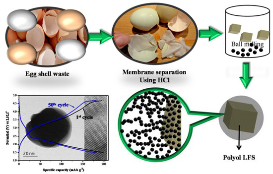
Figure 1.
Schematic representation of LFS@ESM.
2.4. Physical and Electrochemical Characterization
The as-synthesized LFS/C compound was investigated with a PANalyticalX’Pert PRO powder X-ray diffractometer with monochromated using Ni-filtered Cu Kα radiation (λ = 1.5406 Å) to identify structure and phase purity. X-ray photoelectron spectroscopic (XPS) analysis was carried out using a Theta Probe AR-XPS system (Thermo Fisher Scientific, UK). Surface area measurements were executed with Autosorb IQ series (Quantachrome Instruments). The surface morphology and carbon coating of as-synthesized active material were observed with the help of a high resolution transmission electron microscope and selected area electron diffraction (SAED) was performed with a Jeol Jem 2100 TEM analyzer. A Raman spectrum was performed on Renishaw InVia Raman spectrometer with an argon ion laser and charge coupled device detector. Thermogravimetric (TG) studies were performed using TA Instruments’ SDT Q600 thermogravimetric analyzer. Cyclic voltammetry (CV), Galvanostatic charge-discharge and electrochemical impedance spectroscopy was carried out using an eight-channel Bio-Logic battery cycling station BCS 815 (Biologic Science Instrument).
2.5. Electrode Preparation and Coin Cell Fabrication
Electrochemical characterization was analyzed using CR2032 type coin cells. Fabrication of electrode was made in the ratio, 70 wt.% active composite material (LFS@ESM), 20 wt.% carbon (super P) and 10 wt.% binder poly(vinylidene fluoride) (PVdF), as in the earlier reports [33,34]. In order to prepare the homogeneous mixture, all abovementioned materials have been ground with an N-methylpyrrolidone (NMP) solvent. The homogenous slurry was coated on the Al-foil (current collector) and dried in a vacuum oven at 80 °C for 12 h. The fabrication of 2032 coin cells comprising of carbon composite Li2FeSiO4 as cathode, polypropylene as a separator and Li foil was used as a counter electrode with an electrolyte consisting of 1 M LiPF6 dissolved in EC: DMC (1:1 v/v). The fabricated 2032 cells were introduced into a galvanostatic charge-discharge profile within the voltage range of 2.5–4.8 V versus Li+/Li at room temperature. Cyclic voltammetry (CV) curves were measured at a scan rate of 0.5 mV s−1 between 2.5 and 4.5 V.
3. Results and Discussion
Carbon-coated lithium iron orthosilicate cathode (Li2FeSiO4/C) can be prepared with eggshell membrane as a carbon source via the polyol assisted ball miller method, which is represented as LFS@ESM in Figure 2a) to visualize the XRD patterns of the as-prepared Li2FeSiO4/C. The XRD pattern of LFS@ESM samples can be correctly assigned to the orthorhombic phases of Pmn21 which are consistent with the reported values of the lattice parameter: a = 6.2661 Å, b = 5.3295 Å and C = 5.0148 Å elsewhere. In addition, to check the phases, checking of impurity in as-synthesized Lithium iron orthosilicate is very necessary for a cathode [35,36]. No peak appearance at 35° and 43° (for Fe3O4) suggested that as-prepared carbon composite LFS samples have high phase purity. The absence of impurity was further confirmed with XPS analysis discussed later. Here, it should be highlighted that Li2FeSiO4 has poor electronic conductivity of three or four orders of magnitude lower than LiFePO4 [37]. It reduces electrochemical performance of the cathode material to a great extent. Figure 2b) shows the thermogravimetric (TG) curve of as-synthesized LFS@ESM recorded under air flow with the temperature range 25 °C to 800 °C. The TG experiment was performed to determine the amount of carbon in as-synthesized LFS@ESM. All the carbon in the as-synthesized sample was decomposed at elevated temperature. From TG study, approximately 9 wt.% of carbon was detected in the LFS@ESM [38]. This carbon loading could be helped for enhancing electrochemical activity. Also, the 9 wt.% of carbon was in-situ with the LFS materials. Hence, in-situ carbon was not compared with the external carbon (super P). Quantity alone was not enough to interpret the electrochemical behavior. In addition quality was a concern [39]. Therefore, quality has been recognized by the Raman spectrum and nitrogen adsorption and desorption experiment for the as-prepared LFS@ESM, as shown in Figure 2c. From the Raman spectrum, two peaks are pointed out one is for order graphite (G) peak at 1586 cm−1 and another one is for disorder (D) peak at 1340 cm−1, which were aroused due to E2g zone-center and A1g zone-edge mode vibration [40]. The degree of graphitization of LFS@ESM depends on the ratio of integrated intensity of D and G-band (ID/IG) is equal to 0.94, the value less than one indicates that higher graphitized carbon (better quality). Tuinstra and Koenig describe the relation between the in-plane correlation length La and the spectroscopic ID/IG.
where La is a measure of the structural order present in the plane of the graphite material and λ represents the coefficient of excited wavelength (532 nm) [41]. The in-plane correlation length for as-prepared LFS@ESM is 135 nm corresponding to the ratio 0.93 represents the average plane length of layered amorphous carbon.
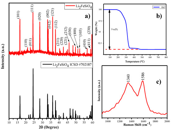
Figure 2.
(a) XRD pattern, (b) thermogravimetric (TG) curve, and (c) Raman spectrum of the as-prepared LFS@ESM.
Further, the porous nature of the carbon composite in LFS (porous) was investigated by using nitrogen adsorption-desorption experiments at 77.3 K. Firstly, the LFS@ESM sample was degassed at 120 °C for 12 h under vacuum for the measurement. According to the IUPAC classification, Figure 3a has clearly indicated the Type II isotherm, correlates the microporous nature with small hysteresis loop. Figure 3b shows the Brunauer–Emmett–Teller (BET) surface area plotted between 1/[Q(P0-P−1)] and relative pressure within the range from 0.07 to 0.30. The calculated average surface area from the graph is 24 m2 g−1. From Figure 3c, the Langmuir surface area was calculated as 53 m2 g−1, which represents the monolayer adsorption of nitrogen. The pore size distribution of the LFS@ESM was derived by using the density functional theory method. As shown in Figure 3d, the micro-, meso- as well as the macro-porous region paved a pathway for Li-ion migration, which lead the electrochemical activities [30]. Generally, the large BET surface area causes side reaction, which is the reason for capacity fading. The composite LFS@ESM exhibits low surface area of 24 m2 g−1 that is comparatively lower then report value 27 m2 g−1 [42]. Therefore, the LFS@ESM holds good stability due to the presence of porous carbon.
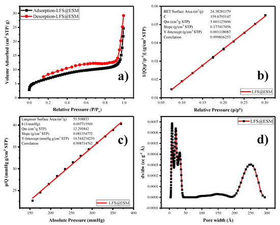
Figure 3.
(a) Nitrogen adsorption-desorption, (b) Brunauer–Emmett–Teller plot (BET), (c) Langmuir surface area, (d) pore size distribution of LFS@ESM.
The X-ray photoelectron spectroscopy is a major tool for identifying the oxidation state of particular chemical species present in the as-prepared material. The survey spectrum of LFS@ESM as shown in Figure 4a which comprised elements such as Li, Si, Fe, O besides C, marked with respect to their corresponding binding energies. The deconvolution of O1s assigned at 531 eV for silicate oxygen in Li2FeSiO4 is shown in Figure 4b. In Figure 4c, other oxidation species of Fe (Fe3+) cannot be identified; only the finger print binding energy observed at 711 and 725 eV, confirmed the oxidation state of Fe2+. Further, it can be confirmed with cyclic voltammetry study. The peak at 101.5 eV detected in Figure 4d is due to the presence of silicate. Consequently, the peak assigned at 55.58 eV is for lithium binding with oxygen (Figure 4e). The deconvolution of the carbon band shown in Figure 4f, provides three different peaks at high intensity for the binding energy 284.11 eV, correlates to the carbon interaction (C–C) and medium intensity at 285.66 eV for carbon and nitrogen binding (C-N). The presence of nitrogen is due to the addition of eggshell membrane (organic matter with some nitrogen content). The minimum peak at 287.56 eV corresponds to carbon and oxygen interaction (O–C=O). These carbon bonds with nitrogen would provide the excess charge carrier for enhancing the electronic conduction.
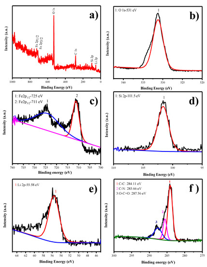
Figure 4.
(a) Survey, (b) O1s, (c) Fe2p, (d) Si2p, (e) Li2s, and (f) C1s x-ray photoelectron spectroscopic (XPS) spectra of LFS@ESM.
Figure 5a–e and Figure 6a–d show the transmission electron microscope (TEM) images of as-synthesized LFS@ESM. The morphology of the composite Li2FeSiO4 with the carbon source eggshell membrane is shown in Figure 5a. An isolated particle with uniformly wrapped carbon on the LFS is clearly indicated in Figure 5b. Figure 5c shows the LFS material with carbon; Figure 5d represents the polycrystalline nature and the atoms of LFS@ESM can be clearly seen in Figure 5e. The d-spacing of 2.97 Å and 3.14 Å were correlated with the oxygen and oxygen interaction in the Li-O tetragonal of LFS [43]. The formation of carbon in LFS@ESM was clearly captured by Figure 6a–d. Figure 6a displays the segregation of carbon molecules as a “t” like structure. The carbon surface with porous nature (Figure 6b) enhances the Li-ion diffusion. Figure 6c shows the surface carbon without any fringe and the SAED pattern indicates the amorphous nature of coated carbon on LFS (Figure 6d).
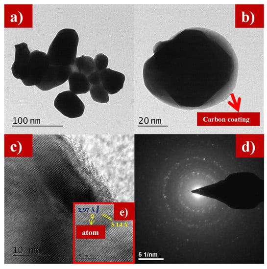
Figure 5.
(a,b) Transmission electron microscope (TEM) images at 100 nm and 20 nm, (c) lattice fringes, (d) selected area electron diffraction SAED, and (e) individual atom of as-synthesized LFS@ESM.
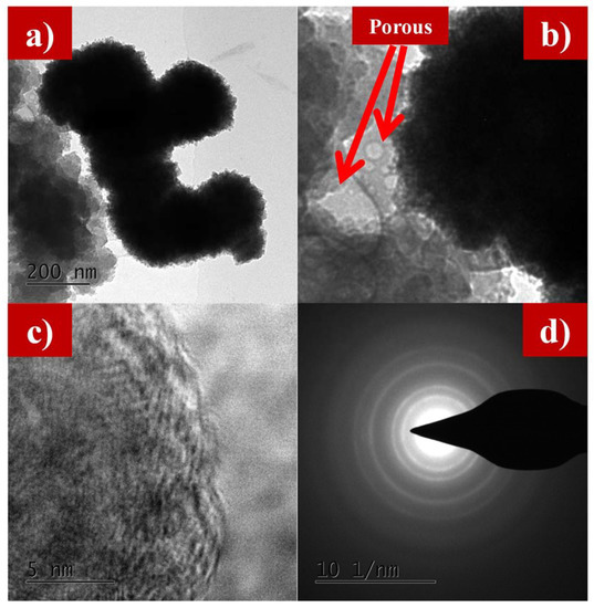
Figure 6.
(a) TEM images at 200 nm, (b) porous nature, (c) amorphous nature, and (d) SAED of carbon in as-synthesized LFS@ESM.
As-prepared carbon-coated LFS material was subjected to electrochemical analysis. Especially, the cyclic voltammetry was recorded for the potential windows of 1.6 to 4.5 V vs Li+/Li with the scan rate 0.5 mV s−1, shown in Figure 7a. Anodic peak potential was observed at 3.10 V due to the conversion of Fe2+ state to Fe3+ with the onset potential of 2.8 V. Consequently, the Fe3+ was reduced to the Fe2+ cathodic peak located at 2.49 V with an onset potential of 2.65 V. The anodic (ip) and cathodic peak (ip) separation was around 0.6 V and the value of 1.03 is obtained from the ratio of anodic to cathodic peak current. With respect to this value, the electrode reaction might be reversible nature. The non-faradic current in this cell is 11.82 mA, due to the facial adsorption phenomenon [44,45]. In Figure 7b, the cyclic performance of the cell cycled at 1 C, for 100 cycles the initial specific discharge capacity is high as compared to other carbon based reports, as cited above. The specific capacity of LFS@ESM was achieved due the structure stability of LFS during insertion and exertion. The higher initial specific capacity is only obtained with the aid of carbon coating at 1 C. The average columbic efficiency of 98.83% with the capacity retention of 80.31% is from the LFS@ESM sample after the 100th cycle. The inset in Figure 7b, displays the galvanostatic charge and discharge profile of the LFS@ESM cycled at 1 C with a potential window of 4.8 to 1.5 V. The charge profiles all the cycles (1 to 100) possess a voltage plateau at ~3.15 V, which represents the transformation of Fe2+ to Fe3+ via anodic reaction and other plateau at ~4.2 V due to the combined capacity effect of nanomaterials in LFS@ESM with a C-rate of 1 C. The excess of specific discharge capacity at first cycle is 194 mAh g−1, which is due to the anion redox mechanism [46], which is comparably higher than the previous report with various carbon sources such as sorbitanlaurat [25], starch and polymer backbone PVA [29], L-ascorbic acid [26] and Indian ink [28]. In the following cycles up to the 100th cycle, the specific capacity gradually reduces to 155 mAh g−1, due to the antisite exchanging process during cycling. From Figure 7c, the rate performance of the LFS@ESM was studied at different C-rate like 0.1, 0.2, 1 and 2 C delivered specific capacities of 258.61, 237.53, 187.02 and 134.11 mAh g−1 for every third cycle. When the cell cycled at 2 C (high) and came back to 0.1 C (low), the LFS@ESM exhibits good reversibility with a difference of 15 mAh g−1 with respect to initial specific capacity of 0.1 C. As seen from Figure 7d the electrochemical impedance spectroscopy (EIS) of the LFS@ESM sample was investigated for fresh cell and cell cycled after the 50th cycle. Both samples have similar behavior for the high frequency region (depressed semicircle) and for the low frequency region. Generally, small intersects at high frequency with real parts is known as solution resistance (Rs), which describes the resistance between the electrode and electrolyte. The electrode kinetics can be identified with the diameter of the semicircle, which is represented as charge transfer resistance (Rct). Li+ diffusion can be understood by using the inclined line generated at low frequency, which is called Warburg diffusion (Zw). The height of the semicircle provides information on the capacity of the material; it is named double layer capacitor (Cdl). From the analysis, the comparison between fresh cell and cell cycled after the 50th cycle has been carried out to identify the behavior of solution resistance, charge transfer resistance, and Warburg resistance respectively. The solution resistance of fresh cell is 6.12 Ω which is increased up to 12.52 Ω after it attains 50 cycles, but in the case of charge transfer resistance exhibits vice versa with a fresh cell resistance 412 Ω decreased 103 Ω for the cell cycled after 50 cycles. These values are obtained from fitting the Electrochemical impedance spectroscopy (EIS) with the equivalent circuit, which is inserted in Figure 7d. The additional inserted picture in the same figure reveals the information on immobile ions in the electrode at fresh cell (green color electrode) and the cell at 50th cycle (red color electrode). The capacity of the materials is reduced, which can be clearly identified from the height of the semicircle for the 50th cycle, which is very low as compared to the fresh cell [47].
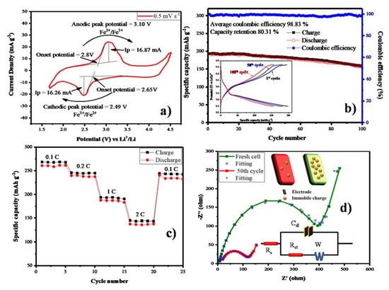
Figure 7.
(a) Cyclic voltammetry, (b) Cycle performance and Galvanostatic charge discharge (inset), (c) Rate performance and (d) Electrochemical impedance spectroscopy of as-synthesized LFS@ESM.
Figure 8a, shows the XRD studies of LFS@ ESM after the cell cycled up to 100 cycles. It was interpreted that listed planes, such as (110), (111), (020), (121), (112), (400) and (103), were matched with the as-synthesized LFS@ESM electrode. However, the electrode underwent tremendous structural disorder during cycling which can be noticed by the change in the intensity of the intense peak. Figure 8b shows the survey spectrum of LFS@ESM after 100 cycles. The presence of chemical elements with atomic percentage was identified as oxygen (33.21%), carbon (22.50%), lithium (35.57%), silicon (5.30%), and iron (3.42%).
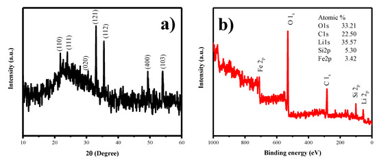
Figure 8.
(a) XRD and (b) XPS spectrum of LFS@ESM after 100 cycles.
4. Conclusions
Carbon composite lithium iron orthosilicate (LFS@ESM) can be prepared via the polyol assisted ball milling method for improving poor electronic conduction, with the carbon derived from the bio-mass eggshell membrane. The XRD pattern confirms the diffraction peak without any phase impurities. The quantity (9 wt.%) and quality (ID/IG = 0.93) of carbon has been justified with TG and Raman analysis. Besides, the existence of layered carbon with an in-plane correlation length La of 135 nm was determined. Subsequently, the calculated monolayer and average surface area is 53 and 24 m2 g−1 with the aid of Langmuir and BET surface area. The BET surface area 24 m2 g−1 has provided the cyclic stability of the material. The micro-, meso- and macro- porous nature of carbon enriches the electrochemical phenomenon. The binding energy observed at 285.66 eV for C–N due to the nitrogen content in eggshell membrane, which leads to improve the electronic conductivity. TEM images clearly show the carbon coating on the LFS, the porous nature of carbon, and the atom arrangements. The value 1.03 is obtained for the ratio of the anodic to cathodic peak current, which means the LFS@ESM electrode was reversible. The higher initial specific capacity is only obtained with the aid of carbon coating at 1 C. LFS@ESM electrode exhibits better columbic efficiency of 98.5% with the capacity retention of 94.7% up to 50 cycles. As a result, ESM improved the specific capacity of LFS. Hence, carbon derived from ESM acts as a potential candidate for energy storage applications.
Author Contributions
Conceptualization, S.M., D.K., and S.R.; methodology, D.K., A.P., R.P., S.M., S.R.; software, D.K., R.P.; validation, S.M., S.R., D.K., R.P., A.P., C.-H.H. and W.-R.L.; formal analysis, D.K.; investigation, D.K., S.M.; resources, S.M., S.R., C.-H.H., W.-R.L.; data curation, D.K., R.P.; writing—original draft preparation, D.K., S.M.; writing—review and editing, S.M., S.R., D.K., W.-R.L. and C.-H.H.; visualization, D.K.; supervision, S.M., S.R.; project administration, S.M., S.R., C.-H.H., W.-R.L.; funding acquisition, S.M., S.R., C.-H.H., W.-R.L. All authors have read and agree to the published version of the manuscript.
Funding
All the authors from Alagappa University acknowledge the financial support by DST-SERB, New Delhi under the physical sciences grant sanctioned vide EMR/2016/006302. All the authors acknowledge the financial support by BSR of University Grants Commission (UGC), New Delhi, India, FIST and PURSE schemes of the Department of Science and Technology (DST), New Delhi, India and the Ministry of Human Resource Development RUSA- Phase 2.0 grant sanctioned to Alagappa University, vide Lt.No.F-24-51/2014 U Policy (TN Multi Gen), Dept. of Education, Government of India. The authors also gratefully acknowledged to Ministry of Science and Technology, Taiwan, Project Grant No.s 108-2811-E-033-500, 108-2911-I-033-502, 108-E-033-MY3 and 108-3116-F-006-002.
Conflicts of Interest
The authors declare no conflict of interest.
References
- Wu, F.; Yushin, G. Conversion cathodes for rechargeable lithium and lithium-ion batteries. Energy Environ. Sci. 2017, 10, 435–459. [Google Scholar] [CrossRef]
- Pfeifer, A.; Dobravec, V.; Pavlinek, L.; Krajačić, G.; Duić, N. Integration of renewable energy and demand response technologies in interconnected energy systems. Energy 2018, 161, 447–455. [Google Scholar] [CrossRef]
- Notton, G.; Nivet, M.-L.; Voyant, C.; Paoli, C.; Darras, C.; Motte, F.; Fouilloy, A. Intermittent and stochastic character of renewable energy sources: Consequences, cost of intermittence and benefit of forecasting. Renew. Sustain. Energy Rev. 2018, 87, 96–105. [Google Scholar] [CrossRef]
- Nikoobakht, A.; Aghaei, J.; Khatami, R.; Mahboubi-Moghaddam, E.; Parvania, M. Stochastic flexible transmission operation for coordinated integration of plug-in electric vehicles and renewable energy sources. Appl. Energy 2019, 238, 225–238. [Google Scholar] [CrossRef]
- Deng, J.; Lu, X.; Liu, L.; Zhang, L.; Schmidt, O.G. Introducing rolled-up nanotechnology for advanced energy storage devices. Adv. Energy Mater. 2016, 6, 1600797. [Google Scholar] [CrossRef]
- Amirante, R.; Cassone, E.; Distaso, E.; Tamburrano, P. Overview on recent developments in energy storage: Mechanical, electrochemical and hydrogen technologies. Energy Convers. Manag. 2017, 132, 372–387. [Google Scholar] [CrossRef]
- Rajkumar, P.; Diwakar, K.; Subadevi, R.; Gnanamuthu, R.; Sivakumar, M. Sulfur cloaked with different carbonaceous materials for high performance lithium sulfur batteries. Curr. Appl. Phys. 2019, 8, 902–909. [Google Scholar] [CrossRef]
- Diouf, B.; Pode, R. Potential of lithium-ion batteries in renewable energy. Renew. Energy 2015, 76, 375–380. [Google Scholar] [CrossRef]
- Hu, S.; Lin, S.; Tu, Y.; Hu, J.; Wu, Y.; Liu, G.; Li, F.; Yu, F.; Jiang, T. Novel aramid nanofiber-coated polypropylene separators for lithium ion batteries. J. Mater. Chem. A 2016, 4, 3513–3526. [Google Scholar] [CrossRef]
- Jia, W.; Li, Z.; Wu, Z.; Wang, L.; Wu, B.; Wang, Y.; Cao, Y.; Li, J. Graphene oxide as a filler to improve the performance of PAN-LiClO4 flexible solid polymer electrolyte. Solid State Ion. 2018, 315, 7–13. [Google Scholar] [CrossRef]
- Mortazavi, B.; Shahrokhi, M.; Madjet, M.E.; Makaremi, M.; Ahzi, S.; Rabczuk, T. N-, P-, As-triphenylene-graphdiyne: Strong and stable 2D semiconductors with outstanding capacities as anodes for Li-ion batteries. Carbon 2019, 141, 291–303. [Google Scholar] [CrossRef]
- Thamodaran, P.; Kesavan, T.; Vivekanantha, M.; Senthilkumar, B.; Barpanda, P.; Sasidharan, M. Operando structural and electrochemical investigation of Li1.5V3O8 nanorods in Li-ion batteries. ACS Appl. Energy Mater. 2019, 2, 852–859. [Google Scholar] [CrossRef]
- Zhao, Y.; Li, J.; Dahn, J. Interdiffusion of cations from metal oxide surface coatings into LiCoO2 during sintering. Chem. Mater. 2017, 29, 5239–5248. [Google Scholar] [CrossRef]
- Ragavendran, K.; Xia, H.; Mandal, P.; Arof, A. Jahn–Teller effect in LiMn2O4: influence on charge ordering, magnetoresistance and battery performance. Phys. Chem. Chem. Phys. 2017, 19, 2073–2077. [Google Scholar] [CrossRef]
- Zhu, Y.G.; Du, Y.; Jia, C.; Zhou, M.; Fan, L.; Wang, X.; Wang, Q. Unleashing the power and energy of LiFePO4-based redox flow lithium battery with a bifunctional redox mediator. J. Am. Chem. Soc. 2017, 139, 6286–6289. [Google Scholar] [CrossRef]
- Guan, Y.; Shen, J.; Wei, X.; Zhu, Q.; Zheng, X.; Zhou, S.; Xu, B. LiFePO4/activated carbon/graphene composite with capacitive-battery characteristics for superior high-rate lithium-ion storage. Electrochim. Acta 2019, 294, 148–155. [Google Scholar] [CrossRef]
- Nytén, A.; Abouimrane, A.; Armand, M.; Gustafsson, T.; Thomas, J.O. Electrochemical performance of Li2FeSiO4 as a new Li-battery cathode material. Electrochem. Commun. 2005, 7, 156–160. [Google Scholar] [CrossRef]
- Singh, S.; Raj, A.K.; Sen, R.; Johari, P.; Mitra, S. Impact of Cl doping on electrochemical performance in orthosilicate (Li2FeSiO4): A density functional theory supported experimental approach. ACS Appl. Mater. Interfaces 2017, 9, 26885–26896. [Google Scholar] [CrossRef]
- Liivat, A.; Thomas, J.; Guo, J.; Yang, Y. Novel insights into higher capacity from the Li-ion battery cathode material Li2FeSiO4. Electrochim. Acta 2017, 223, 109–114. [Google Scholar] [CrossRef]
- Li, L.; Han, E.; Mi, C.; Zhu, L.; Dou, L.; Shi, Y. The effect of Ni or Pb substitution on the electrochemical performance of Li2FeSiO4/C cathode materials. Solid State Ion. 2019, 330, 24–32. [Google Scholar] [CrossRef]
- Wang, W.; Liang, H.; Zhang, L.; Savilov, S.V.; Ni, J.; Li, L. Carbon nanotube directed three-dimensional porous Li2FeSiO4 composite for lithium batteries. Nano Res. 2017, 10, 229–237. [Google Scholar] [CrossRef]
- Hu, L.-H.; Wu, F.-Y.; Lin, C.-T.; Khlobystov, A.N.; Li, L.-J. Graphene-modified LiFePO4 cathode for lithium ion battery beyond theoretical capacity. Nat. Commun. 2013, 4, 1687. [Google Scholar] [CrossRef]
- Qu, L.; Li, M.; Bian, L.; Du, Q.; Luo, M.; Yang, B.; Yang, L.; Fang, S.; Liu, Y. A strontium-doped Li2FeSiO4/C cathode with enhanced performance for the lithium-ion battery. J. Solid State Electrochem. 2017, 21, 3659–3673. [Google Scholar] [CrossRef]
- Sun, S.; Ghimbeu, C.M.; Vix-Guterl, C.; Sougrati, M.-T.; Masquelier, C.; Janot, R. Synthesis of Li2FeSiO4/carbon nano-composites by impregnation method. J. Power Sources 2015, 284, 574–581. [Google Scholar] [CrossRef]
- Qu, L.; Liu, Y.; Fang, S.; Yang, L.; Hirano, S.-I. Li2FeSiO4 coated by sorbitanlaurat-derived carbon as cathode of high-performance lithium-ion battery. Electrochim. Acta 2015, 163, 123–131. [Google Scholar] [CrossRef]
- Yan, Z.; Cai, S.; Miao, L.; Zhou, X.; Zhao, Y. Synthesis and characterization of in situ carbon-coated Li2FeSiO4 cathode materials for lithium ion battery. J. Alloy. Compd. 2012, 511, 101–106. [Google Scholar] [CrossRef]
- Milović, M.; Jugović, D.; Mitrić, M.; Dominko, R.; Stojković-Simatović, I.; Jokić, B.; Uskoković, D. The use of methylcellulose for the synthesis of Li2FeSiO4/C composites. Cellulose 2016, 23, 239–246. [Google Scholar] [CrossRef]
- Fujita, Y.; Iwase, H.; Shida, K.; Liao, J.; Fukui, T.; Matsuda, M. Synthesis of high-performance Li2FeSiO4/C composite powder by spray-freezing/freeze-drying a solution with two carbon sources. J. Power Sources 2017, 361, 115–121. [Google Scholar] [CrossRef]
- Zhou, H.; Einarsrud, M.-A.; Vullum-Bruer, F. PVA-assisted combustion synthesis and characterization of porous nanocomposite Li2FeSiO4/C. Solid State Ion. 2012, 225, 585–589. [Google Scholar] [CrossRef]
- Chen, Z.; Qiu, S.; Cao, Y.; Qian, J.; Ai, X.; Xie, K.; Hong, X.; Yang, H. Hierarchical porous Li2FeSiO4/C composite with 2 Li storage capacity and long cycle stability for advanced Li-ion batteries. J. Mater. Chem. A 2013, 16, 4988–4992. [Google Scholar] [CrossRef]
- Raja, M.; Stephan, A.M. Natural, biodegradable and flexible egg shell membranes as separators for lithium-ion batteries. Rsc Adv. 2014, 4, 58546–58552. [Google Scholar] [CrossRef]
- Karuppiah, D.; Palanisamy, R.; Rengapillai, S.; Liu, W.-R.; Huang, C.-H.; Marimuthu, S. Carbon loaded nano-designed spherically high symmetric Lithium iron orthosilicate cathode materials for Lithium secondary batteries. Polymers 2019, 11, 1703. [Google Scholar] [CrossRef] [PubMed]
- Ferrari, S.; Mozzati, M.C.; Lantieri, M.; Spina, G.; Capsoni, D.; Bini, M. New materials for Li-ion batteries: synthesis and spectroscopic characterization of Li2(FeMnCo)SiO4 cathode materials. Sci. Rep. 2016, 6, 27896. [Google Scholar] [CrossRef] [PubMed]
- Qiu, H.; Zhu, K.; Li, H.; Li, T.; Zhang, T.; Yue, H.; Wei, Y.; Du, F.; Wang, C.; Chen, G.; et al. Mesoporous Li2FeSiO4@ordered mesoporous carbon composites cathode material for lithium-ion batteries. Carbon 2015, 87, 365–373. [Google Scholar] [CrossRef]
- Sirisopanaporn, C.; Masquelier, C.; Bruce, P.G.; Armstrong, A.R.; Dominko, R. Dependence of Li2FeSiO4 electrochemistry on structure. J. Am. Chem. Soc. 2010, 133, 1263–1265. [Google Scholar] [CrossRef] [PubMed]
- Sasaki, H.; Nemoto, A.; Miyahara, M.; Katayama, S.; Akimoto, Y.; Nakajima, A.; Hirano, S.-I. Synthesis of Li2FeSiO4 nanoparticles/carbon composite for cathode materials by spray pyrolysis method. J. Ceram. Soc. Jpn. 2016, 124, 963–966. [Google Scholar] [CrossRef]
- Zeng, Y.; Chiu, H.-C.; Rasool, M.; Brodusch, N.; Gauvin, R.; Jiang, D.-T.; Ryan, D.H.; Zaghib, K.; Demopoulos, G.P. Hydrothermal crystallization of Pmn21 Li2FeSiO4 hollow mesocrystals for Li-ion cathode application. Chem. Eng. J. 2019, 359, 1592–1602. [Google Scholar] [CrossRef]
- Thayumanasundaram, S.; Rangasamy, V.S.; Seo, J.W.; Locquet, J.-P. A combined approach: Polyol synthesis of nanocrystalline Li2FeSiO4, doping multi-walled carbon nanotubes, and ionic liquid electrolyte to enhance cathode performance in Li-ion batteries. Electrochim. Acta 2017, 258, 1044–1052. [Google Scholar] [CrossRef]
- Doeff, M.M.; Hu, Y.; McLarnon, F.; Kostecki, R. Effect of surface carbon structure on the electrochemical performance of LiFePO4. Electrochem. Solid-State Lett. 2003, 6, A207–A209. [Google Scholar] [CrossRef]
- Lu, X.; Wei, H.; Chiu, H.-C.; Gauvin, R.; Hovington, P.; Guerfi, A.; Zaghib, K.; Demopoulos, G.P. Rate-dependent phase transitions in Li2FeSiO4 cathode nanocrystals. Sci. Rep. 2015, 5, 8599. Available online: https://www.nature.com/articles/srep08599#supplementary-information (accessed on 26 February 2015). [CrossRef]
- Panitz, J.-C.; Novák, P. Raman microscopy as a quality control tool for electrodes of lithium-ion batteries. J. Power Sources 2001, 97, 174–180. [Google Scholar] [CrossRef]
- Kumar, A.; Jayakumar, O.; Naik, V.M.; Nazri, G.; Naik, R. Improved electrochemical properties of solvothermally synthesized Li2FeSiO4/C nanocomposites: A comparison between solvothermal and sol-gel methods. Solid State Ion. 2016, 294, 15–20. [Google Scholar] [CrossRef]
- Jugović, D.; Milović, M.; Ivanovski, V.N.; Avdeev, M.; Dominko, R.; Jokić, B.; Uskoković, D. Structural study of monoclinic Li2FeSiO4 by X-ray diffraction and Mössbauer spectroscopy. J. Power Sources 2014, 265, 75–80. [Google Scholar] [CrossRef]
- Xu, Y.; Shen, W.; Wang, C.; Zhang, A.; Xu, Q.; Liu, H.; Wang, Y.; Xia, Y. Hydrothermal synthesis and electrochemical performance of nanoparticle Li2FeSiO4/C cathode materials for lithium ion batteries. Electrochim. Acta 2015, 167, 340–347. [Google Scholar] [CrossRef]
- Suresh, S.; Ulaganathan, M.; Venkatesan, N.; Periasamy, P.; Ragupathy, P. High performance Zinc-Bromine redox flow batteries: role of various carbon felts and cell configurations. J. Energy Storage 2018, 20, 134–139. [Google Scholar] [CrossRef]
- Seo, D.-H.; Lee, J.; Urban, A.; Malik, R.; Kang, S.; Ceder, G. The structural and chemical origin of the oxygen redox activity in layered and cation-disordered Li-excess cathode materials. Nat. Chem. 2016, 8, 692. [Google Scholar] [CrossRef]
- Zhou, Z.; Zhang, H.; Zhou, Y.; Qiao, H.; Gurung, A.; Naderi, R.; Elbohy, H.; Smirnova, A.L.; Lu, H.; Chen, S.; et al. Binder free hierarchical mesoporous carbon foam for high performance Lithium ion battery. Sci. Rep. 2017, 7, 1440. [Google Scholar] [CrossRef]


© 2020 by the authors. Licensee MDPI, Basel, Switzerland. This article is an open access article distributed under the terms and conditions of the Creative Commons Attribution (CC BY) license (http://creativecommons.org/licenses/by/4.0/).