Article

A Framework for the Synthesis of Optimum Operating Profiles Based on Dynamic Simulation and a Micro Genetic Algorithm

by
Erik Rosado-Tamariz
1,2,*,
Miguel A. Zuniga-Garcia
1,2,*,
Alfonso Campos-Amezcua
2,* and
Rafael Batres
1,*
1
School of Engineering and Sciences, Tecnologico de Monterrey, Av. Eugenio Garza Sada Sur No. 2501, Col. Tecnologico, Monterrey 64849, Mexico
2
Instituto Nacional de Electricidad y Energías Limpias (INEEL), Av. Reforma 113, Col. Palmira, Cuernavaca CP 62490, Mexico
*
Authors to whom correspondence should be addressed.
Energies 2020, 13(3), 677; https://doi.org/10.3390/en13030677
Submission received: 19 December 2019 / Revised: 6 January 2020 / Accepted: 7 January 2020 / Published: 5 February 2020
(This article belongs to the Special Issue Optimal Design and Operation of Sustainable Energy Systems)

Abstract

:
This paper presents an approach to managing the thermal power plant’s flexible operation based on the steam generation process optimization. A strategy at the process level, as a first step in the operational optimization of the entire power plant, is proposed. The proposed approach focuses on minimizing the drum boiler startup time, since it is considered the most critical element in the steam generation process and in the thermal power plant’s efficient operation. An approach that addresses the problem to find the optimal sequences of control valves that minimize the drum boiler startup time as a dynamic optimization problem is proposed. To solve the optimization problem, a dynamic optimization framework based on a micro genetic algorithm (mGA) coupled with a dynamic simulation model is implemented. The dynamic simulation model is validated against data available in the literature, and the proposed optimization algorithm is characterized by the use of variable length chromosomes and the use of small population sizes. The results show that optimized operating profiles minimize the drum boiler startup time by at least 35 percent and generate control valve operating sequences that must be carried out to achieve the desired profile, while the structural integrity constraints are fulfilled at all times.

1. Introduction

In order to achieve a reliable energy supply, the balance of electricity supply and demand must be guaranteed at all times. Even a small mismatch in the balance may disturb the power system frequency and affect its reliability and availability [1]. Furthermore, an optimal co-existence of both conventional and renewable technologies is required. The operational flexibility of the electric power system plays a key role in achieving such balance. This operational flexibility is the capability of a power system to cope with the expected and unexpected changes in electricity demand and energy supply [2]. The electric power system operational flexibility can be addressed from different fronts such as demand response, energy storage, and flexible generation [3]. Demand response refers to demand-side management programs, in which demand patterns are fitted to better match the changes in the electricity supply [4]. Likewise, demand response provides consumers an opportunity to play a role in the operation of the grid by regulating their electricity consumption. To best balance electricity demand and energy supply through demand management, mainly demand and renewable energy forecasting methods are used, as well as smart grid designs [5]. Operational flexibility can also be achieved by means of energy storage. Energy storage relates to the accumulation of hydro, electrical, or thermal energy to later be used. Even though hydro storage is dominant, it is mainly limited by its geographic location and water availability, limiting its growth. Regarding the electrical and thermal energy storage, several technologies are available on the market with different degrees of maturity, capacity, and discharge duration. However, cost effective and commercially available large scale energy storage technology is yet to be developed [6].
Flexible generation focuses on satisfying the residual load of the electric power system through conventional power plants. The residual load is represented by subtracting the feed-in of renewable energy sources from the load profile [7]. Flexible generation can be improved by redesigning critical power plant components, identifying new market mechanisms, and defining new operational strategies [8].
According to data from the International Energy Agency [5], in the short term to medium term, flexible generation will be considered as the most effective solution to deliver power system operational flexibility. Since it is a more mature approach, it is less constrained by capacity and geographic location than demand response and energy storage. In this regard, the evaluation of flexible generation capacity in conventional thermal power plants has been reported in previous works such as those by Kubik et al. [9], Hentschel and Spliethoff [10], and Gonzalez-Salazar et al. [3], where they concluded that the most suitable power plants to provide operational flexibility to the electric power system are the simple cycle gas turbine, high efficiency coal fired, and combined cycle power plants. Likewise, they identified that the development trend of these power plants is focused on operational improvement in terms of increasing ramp rates, decreasing minimum power load, and the development of the improvements of cyclic operational capabilities. In this context, research such as that developed by Casella et al. [11], Almodarra et al. [12], Anisimov et al. [13], Rossi et al. [14], Mei Ji et al. [15], and Liu and Karimi [16] addressed the flexible generation challenge through the conventional thermal power plants operating profiles’ optimization. On the other hand, as a first step for the analysis of the whole power plant and using a hierarchical optimization strategy, the works of Franke et al. [17], El-Guindy et al. [18], Elshafei et al. [19], Belkhir et al. [20], and Zhang et al. [21] proposed to manage the operation of the power plant using a process level approach. Since it is widely known that the steam generation process is one of the most important in thermal power plants, they focused their efforts on designing optimal steam generation profiles, obtaining encouraging results in their research.
In thermal power plants, steam generation is carried out through a steam generator or a boiler. The steam generator is a device that produces high pressure and high temperature steam for energy generation. This process is carried out by transferring heat from flue gases from a furnace or a gas turbine exhaust to water contained in the riser and downcomer waterwalls in order to produce steam through a boiling process. Then, in a pressure vessel known as a drum boiler, the saturated steam is separated from liquid water. The steam is dried inside the drum boiler and sent to the superheater to be heated above the saturation temperature, then it is piped through the main steam lines to the steam turbine in order to produce electrical power. Due to its important function in the steam generation process, the drum boiler is considered the most critical element in the steam generator, since it is in this equipment where the steam quality and steam flow rate that influence the generation of energy in the steam turbine are regulated. The steam generator typically is composed of the drum boiler, mud drum, a water circulation loop, feedwater system, and recirculation pumps, as well as a thermal energy supply system. The water circulation loop is composed of the downcomer and riser waterwalls. A drum boiler’s basic configuration is illustrated in Figure 1.
The heat supply and feedwater flow rate are the main controlled variables that determine the behavior of the steam generation process. Therefore, their operation must be improved in order to avoid dangerous operating scenarios, such as boiler swell/shrink phenomena and overheating of thick-walled devices. Boiler swell/shrink phenomena are produced when a sudden change in the steam pressure causes the steam drum to go into violent oscillation, which can cause the boiler to trip [19]. Likewise, boiler swell/shrink is related to an instant change of the liquid water level in the drum boiler, induced by steam quality variations in the riser waterwall [19]. Overheating is related to a fast heat supply, which induces severe temperature variations in the thick-walled devices causing high thermal stresses. Since these stresses lead to fatigue or even material failures, it needs to be held within given limits [22]. Therefore, approaches are needed to obtain operating profiles that minimize the drum boiler startup time to satisfy the steam demand required by the power plant while reducing thermal stresses.
This paper is structured as follows: Section 2 contains the literature review. A description of the proposed approach based on dynamic simulation and a micro genetic algorithm is presented in Section 3. Next, the case study is described in Section 4. Then, in Section 5, the experiments and results are presented. Finally, Section 6 contains the conclusions and future work of this research project.

2. Literature Review

Researchers have focused their attention on studying dynamic simulation and optimization of steam generators in order to improve the flexible generation capabilities of thermal power plants. Specifically, previous work focuses on the study of power plant transient behavior as a means to propose and design optimal operational strategies. To that end, dynamic simulation models were developed based on mass, momentum, and energy conservation laws.
Early simulation models of power plants steam generators were based on a simple nonlinear boiler turbine unit. Some of these models were proposed by Astrom and Euckland [23]. Astrom and Bell [24] improved the linear model developed by Astrom and Euckland and validated it with experimental data, finding that the model was capable of capturing the major dynamical behavior of the system. Later, Peet and Leung [25] proposed a dynamic simulation model to design a drum boiler based on the requirements of a conventional thermal power plant’s operation to achieve flexible and economic production of steam. Subsequently, Bell and Astrom [26] developed a nonlinear model of a drum boiler based on the principles of their initial model, and its transient performance was validated against real power plant data. In the control arena, Flynn and O’Malley [27] developed a drum boiler dynamic simulation model and used it in the study and design of a new control philosophy to meet the operational requirements of a large fossil fuel power plant. Over the years, drum boiler models grew in complexity and accuracy, mainly by replacing empirical coefficients with real operating parameters. A commonly cited model is that of Astrom and Bell [28], which was a nonlinear dynamic model in which the downcomer, riser, and drum dynamic behaviors were based on a global balance of conservation laws and required few physical parameters to have a simple and robust system.
Subsequently, Wen and Ydstie [29], El-Guindy et al. [18], Elshafei et al. [19], Belkhir et al. [20], and Zhang et al. [21] developed simulation models based on the theoretical model proposed by [28], using advanced modeling and simulation techniques.
Regarding the operation of power plants, several works have been reported in the literature that dealt with the optimization of steam generation from a process point of view. Franke et al. [17] developed a nonlinear dynamic model of a drum boiler based on the Modelica language using the fluid libraries [30]. Their model had three control inputs in terms of feedwater flow rate, heat supply, and steam outlet. They solved a dynamic optimization problem using a sequential quadratic programming (SQP) algorithm. Using this approach, the startup time could be reduced by about 30%. Kruger et al. [31] proposed a quadratic programming optimization approach to determine the optimal values of steam pressure and steam temperature in a startup process. Their model took into account hard constraints such as control bounds and stress levels for the drum and header. They concluded that their optimization model was capable of minimizing both fuel consumption and startup time. Li et al. [32] developed a drum boiler startup simulation program that focused on reducing the operational time and minimizing fuel consumption during startup or shutdown scenarios. They used a distributed parameter method to simulate the heat transfer process in the waterwalls, the superheater, the reheater, and the economizer, while heat transfer in the drum and the downcomer was simulated by lumped parameter analysis. Moreover, Belkhir et al. [20] minimize the startup time of a steam generator. The proposed startup strategy was focused on achieving reference state variables in terms of steam mass flow rate and the pressure inside the drum to fulfill the steam requirements in the power train. The startup process was formulated as an optimal control problem that focused on minimizing a quadratic objective function under physical and operational constraints. The physical constraints were related to the structural integrity of thick-walled components due to higher thermal stresses. The drum boiler model was developed in the commercial Modelica environment Dymola using the fluid and thermal libraries. A framework developed on the JModelica environment and interior point optimizer algorithm (IPOPT) was used to solve the optimization problem. Their results were compared against a classical startup strategy, and the optimized profiles reached desired states in a shorter time without violating the operational and physical constraints. Zhang et al. [21] presented a numerical investigation on the dynamic analysis of the steam and water system of the natural circulation boiler developed in the environment of MATLAB/Simulink. They proposed a boiler modeling based on the Astrom–Bell model with specific parameters to simulate the dynamic analysis of the steam-water system. Their model assumed that steam was saturated along with the whole evaporating system. They solved the model using the ode45 algorithm, which is based on the fourth-order Runge–Kutta and Dormand–Prince methods. The boiler startup was formulated to get a better curve of the startup in order to save water and fuel. The input parameters were heat flow, the mass flow rate of steam, and the mass flow rate of feedwater, which were changing with time. After that, they brought about a plan for a cold startup, obtaining a cold start-up curve that could be used as a reference for practical production.
In general, there has been some research focused on optimizing the drum boiler startup process with the aim to enhance the operating capabilities of thermal power plants. Likewise, advanced techniques of simulation, control, and optimization have been used to solve the optimization problem and thereby minimize the transition time in the operation of thermal power plants. Despite this, previous work previous has not taken into account the identification and generation of actions required to reach this objective and thus having an integral design of optimal operating procedures.
Investigations such as those reported by [17,20,21] showed encouraging results; however, they had limited applicability since their objective was to minimize startup times considering thermal stresses as the main constraint, regardless of how they must operate the drum boiler to achieve the goal states of the critical state variables. On the other hand, reported works with interesting proposals [21,33,34] limited their applicability, since they were developments for specific problems; in many cases, the simulation model was embedded within the optimization tool and it was not possible to scale them for more complex problems such as a power plant. In the same way, the works in [20,33,35,36] propose approaches using commercial tools for the coupling of a simulation optimization integral system. The drawback is that these tools operate as black boxes, which limited the development and scaling of the research carried out. Moreover, they are also limited to a certain type of optimization algorithms.
Although gradient based methods such as [37,38] can solve dynamic optimization problems quickly, they have three key weaknesses: difficult implementation (depending on the problem); intolerance to noisy objective function spaces; and location of local optimum solutions rather than a global optimum [39].
To overcome the limitations of previous works, the present research aims to design, in an integral way, the drum boiler startup optimal operating procedure in order to enhance the operational capacities of thermal power plants. A dynamic optimization framework based on a micro genetic algorithm (mGA) coupled with a dynamic simulation model is proposed. The integral design of the optimal operating procedure involves the operating profiles that minimize the drum boiler startup times to satisfy the steam demand required by the power plant, as well as the corresponding control actions (operations) and their sequence to take the drum boiler from an initial state to a goal state. A metaheuristic optimization algorithm characterized by the uses of variable length chromosomes and the use of small population sizes is implemented. A scalable dynamic simulation model using the modeling and simulation environment OpenModelica is developed. Likewise, an open interface based on the C# code is developed in order to connect the dynamic simulator with the optimization module.

3. Proposed Approach

3.1. Problem Statement

The problem consisted of finding the optimal sequence of control valves that minimized the time needed to take the drum boiler from an initial state to a goal state. This problem was formulated as a dynamic optimization problem, involving a dynamic simulation model with variables whose values changed in time. The optimization was constrained by thermal stress in the thick-walled drum, caused by a spatial temperature difference.
A typical drum boiler configuration consists of a water circulation loop and a heat energy system [40]. The water circulation loop is composed of a steam drum, mud drum, the downcomer waterwalls tubes, and the riser waterwalls tubes. The steam drum is the top drum of a boiler where all of the generated steam is collected before entering the distribution system. The steam drum has the function of controlling the steam generator water level since the loss of water level can damage boiler equipment, and excessively high water levels can result in wet steam, which can cause operational upsets. The mud drum is the lower drum in a boiler. The mud drum is filled completely with water and has the function of a settling point for solids in the boiler feedwater. Sediment accumulated in the bottom of the mud drum is removed by water blowdown. Downcomer waterwalls are a set of pipes leading from the top to the bottom of the drum boiler, and through them, the water is transferred from the steam drum to the mud drum. The downcomer is the cooler water line that goes from the upper drum to the lower drum. Riser waterwall tubes contain boiler feedwater that is heated by radiant heat from the flue gas and boiled to produce steam that flows upward to the steam drum. The riser is the hotter water line that goes from the mud drum to the steam drum. The heat energy system supplies heat from the flue gases to the water flowing down the riser waterwall tubes in order to regulate the boiling process. Gravity induces the saturated steam to rise, leading to circulation in the riser-drum-downcomer loop. Through a centrifugal pump, the feedwater is supplied to the steam drum, and saturated steam is taken from the drum through a control valve to the superheaters and the turbine. A 3D model of a typical drum boiler configuration being applied to a 500 MW thermal power plant and a saturated steam mass-flow rate of 185 kg/s is shown in Figure 2.

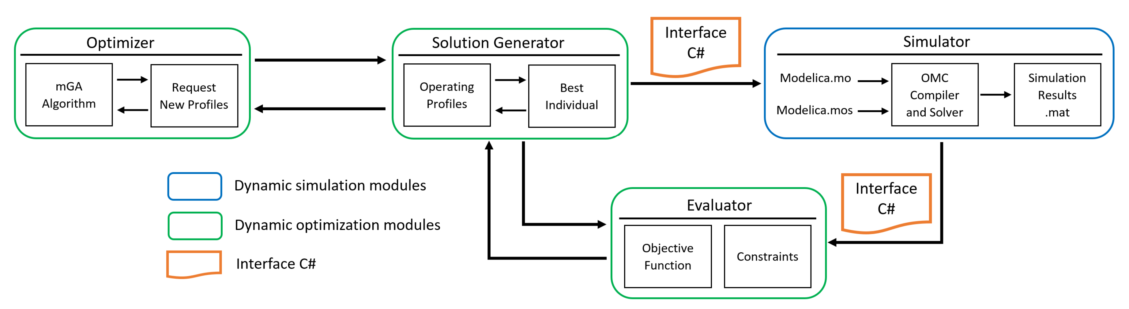
3.2. Proposed Framework

In order to address the problem of finding the optimal control valve sequences that minimize the drum boiler startup time, a dynamic optimization framework based on a micro genetic optimization algorithm (mGA) coupled with a dynamic simulation model was proposed. The architecture of the framework is shown in Figure 3.
This framework consisted mainly of four modules: a simulator developed on the OpenModelica environment, the optimizer, a solution generator, and the evaluator, which were implemented in C# code. Likewise, an interface based on C# code was developed in order to connect the drum boiler simulator with the framework optimization modules.
To solve the dynamic optimization problem, the optimizer executes the micro-genetic algorithm and interacts with the solution generator, submitting requests for new solutions. The main role of the solution generator is to create an individual, which represents an operation profile. Each individual is composed of three chromosomes, which contain information about the control valve positions, the valve positions times, and the number of repetitions of each valve position. For each individual that is generated, the solution generator creates a file that contains the valves operating sequences of the heat supply and steam flow rate at the outlet of the drum boiler. Then, the C# interface translates this file to Modelica code and merges it with the Modelica.mo file of the simulator. The Modelica.mos file contains the simulator script and has the function of running the simulations using the OpenModelica OMC compiler. The simulation results file .mat through the C# interface is sent to the evaluator module in order to calculate the objective function and evaluates the constraints. This information is then passed to the solution generator to continue the cycle of the framework through the mGA algorithm until achieving the stop criteria.

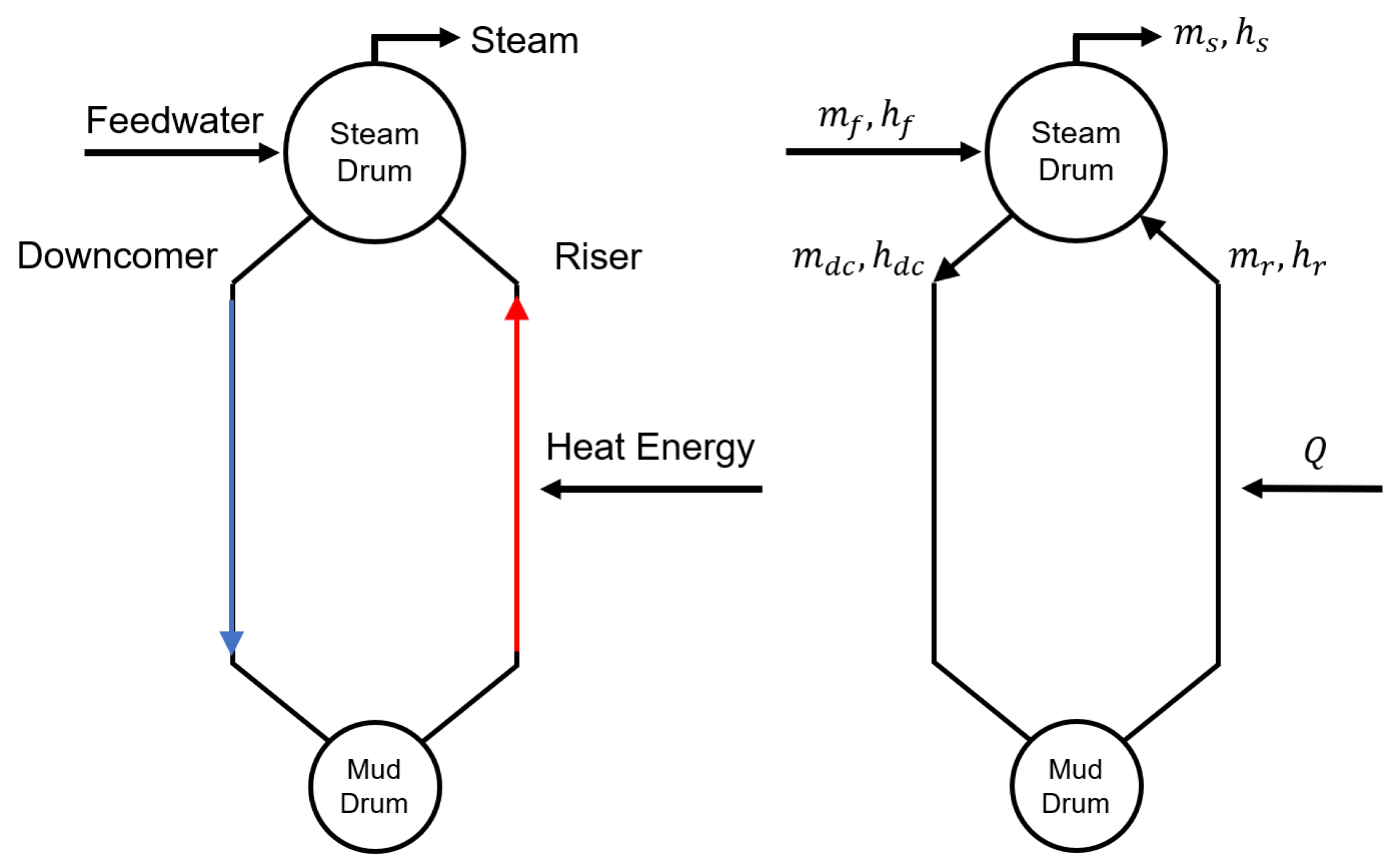
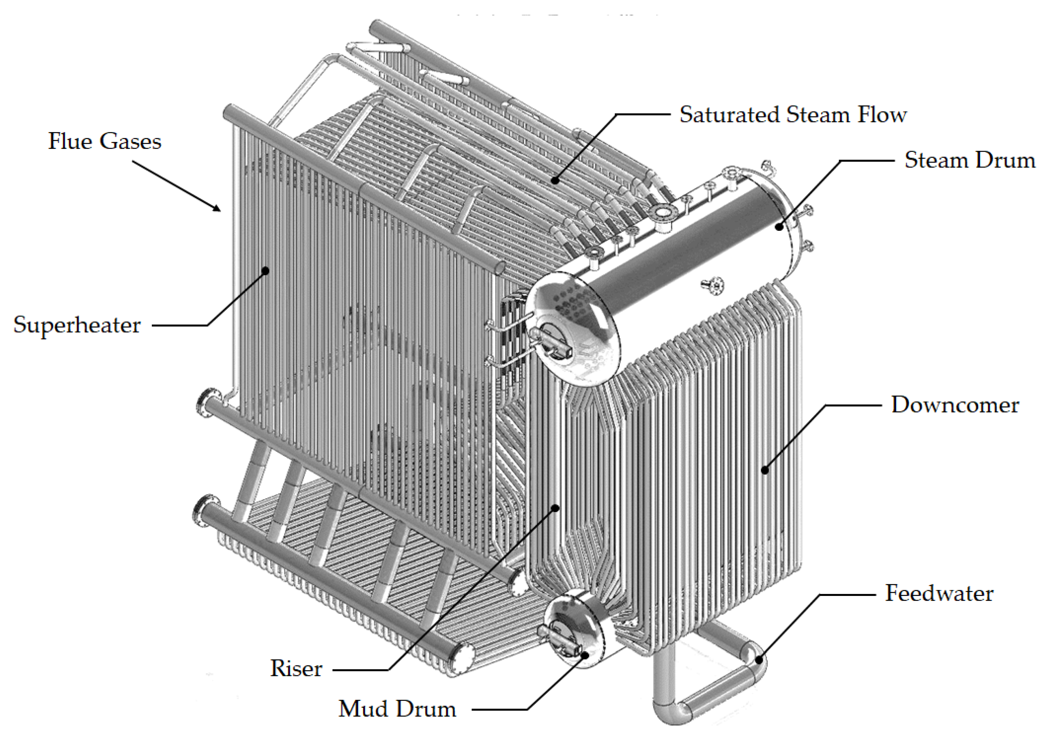
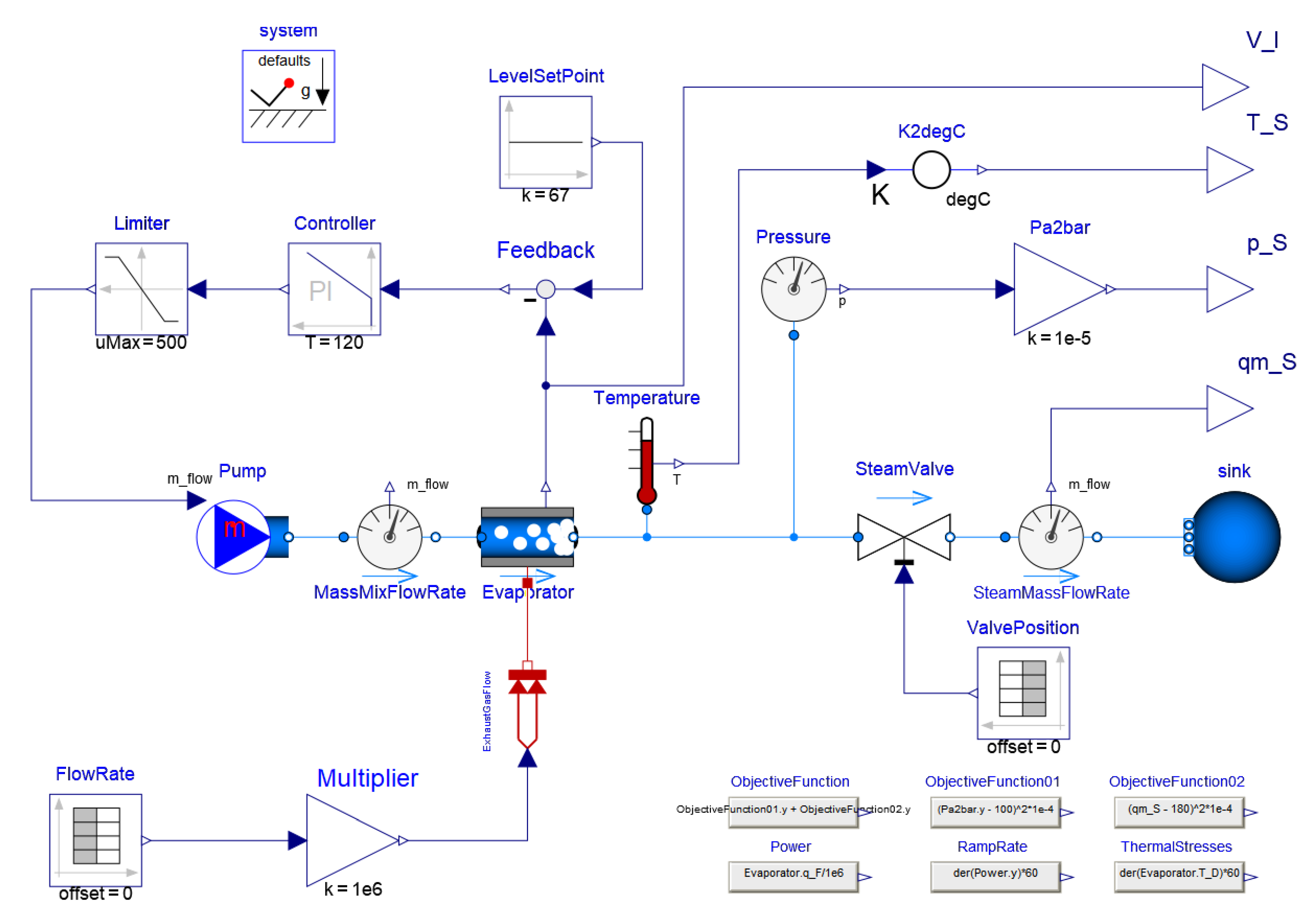
3.3. Simulation Model

The simulation model was based on the Astrom and Bell model [28]. The model assumed a global mass balance and water co-existence in two phases: liquid and steam inside the drum, as well as a water thermodynamic state at the phase boundary. Since the drum boiler had complex configurations and geometries in this model, global system flows, volumes, and masses were considered. The model ignored spatial variations in the process variables such as individual geometric features and fin and pipes arrangements in the risers and downcomers. Moreover, this model did not consider heat losses between the water inside the drum and the drum and pipes’ metal walls. Therefore, it was assumed that the water and metal temperatures were in thermodynamic equilibrium within the drum. Despite these simplifications, the resulting lumped parameter model was capable of capturing the overall behavior of the drum boiler. The behavior of the boiler furnace in a coal fired power plant or exhaust gases of a gas turbine was modeled by means of a heat supply system that heated and evaporated the water in the rising tubes.
The global mass balance in the drum boiler is shown in Equation (1):
d d t [ ρ s V s t + ρ w V w t ] = q f q s
where ρ s is the specific steam density, V s t is the total system steam volume, ρ w is the specific water density, V w t is the total system water volume, q f is the feedwater mass flow rate, and q s is the steam mass flow rate.
The global energy balance in the drum boiler can be written as:
d d t [ ρ s h s V s t + ρ w h w V w t p V t + m t C p t m ] = Q + q f h f q s h s
where h s is the specific steam enthalpy, h w is the specific water enthalpy, p is the mixture pressure, V t is the total system volume, m t is the total mass of the metal tubes and the drum, C p is the specific heat of the metal, Q is the heat supplied to the tube, and h f is the specific feedwater enthalpy.
The total volume of the drum, downcomer, and riser ( V t ) is determined by the total steam and water volumes as shown below:
V t = V s t + V w t
The global mass and energy balance for the riser section is represented by Equations (4) and (5), respectively:
d d t [ ρ s α v V r + ρ w ( 1 α v ) V r ] = q d c q r
d d t [ ρ s h s α v V r + ρ w h w ( 1 α v ) V r p V r + m r C p t s ] = Q + q d c h w ( α r h c + h w ) q r
where α v is the average volume fraction, V r is the riser volume, m r is the riser mass, t s is the steam temperature, q d c is the downcomer flow rate, α r is the steam quality at the riser outlet, and h c = h s h w is the condensation enthalpy.
The momentum balance for the downcomer-riser loop is:
( L r L d c ) d q d c d t = ( ρ w ρ s ) α v V r g k ( q d c ) 2 2 ρ w A d c
where L r is the riser lengths, L d c is the downcomer lengths, A d c is the downcomer area, and k is a dimensionless friction coefficient.
The mass balance for the steam under the liquid level in the steam drum is:
d d t ( ρ s V s d ) = α r q r q s d q c d
where V s d is the volume of steam under the liquid level in the drum, q s d is the steam flow rate through the liquid surface in the drum, q r is the flow rate out of the risers, and q c d is condensation flow.
The proposed simulation model formulation assumed a thermodynamic equilibrium between water and steam inside the steam drum. Feedwater from the condenser enters the steam drum, and saturated steam is extracted.
The behavior of condensation flow in the drum and the steam flow rate through the liquid surface in the drum are given by Equations (8) and (9):
q c d = h w h f h c q f + 1 h c ρ s V s d d h s d t + ρ w V w d d h w d t + ( V s d V w d ) d p d t + m d C p d t s d t
q s d = ρ s T d ( V s d ( V s d ) 0 ) + α r q d c + α r β ( q d c q r )
where V w d is the volume of water under the liquid level in the drum, m d is the mass in the drum, ( V s d ) 0 denotes the volume of steam in the drum in the hypothetical situation when there is no condensation of steam in the drum, and T d is the residence time of the steam in the drum, which is approximated by:
T d = ρ s ( V s d ) 0 q s
From the distribution of the steam below the drum level, the drum level can be modeled using the equation of water in the drum:
V w d = V w t V d c ( 1 α v ) V r
Since the drum has a complex geometry configuration, the liquid level changes can be described by the wet surface A d at the operating level. The deviation of the drum level l measured from its normal operating level is:
l = V w d + V s d A d = l w l s
The term l w represents level variations caused by changes in the amount of water in the drum, and the term l s represents variations caused by the steam in the drum.
In summary, the state variables that describe the behavior of the system are: drum pressure p, total water volume V w t , steam quality at the riser outlet α r , and volume of steam under the liquid level in the drum V s d . The parameters required by the model are: drum volume V d , riser volume V r , downcomer volume V d c , drum area A d at the normal operating level, total metal mass m t , total riser mass m r , friction coefficient in downcomer-riser loop k, residence time T d of steam in the drum, and parameter β in the empirical equation steam flow rate through the liquid surface in the drum q s d .

3.4. Thermal Stress Modeling

The thermal stresses were determined according to the general equations for radial, tangential, and axial thermal stresses in a thick-walled pressure vessel under a radial thermal gradient shown in the work of Mirandola et al. [41]:
σ r = α E ( 1 μ ) r 2 r 2 a 2 b 2 a 2 a b T r d r a r T r d r
σ t = α E ( 1 μ ) r 2 r 2 + a 2 b 2 a 2 a b T r d r a r T r d r T r 2
σ a = α E ( 1 μ ) 2 b 2 a 2 a b T r d r T
σ V M = ( σ 1 ) 2 + ( σ 2 ) 2 + ( σ 3 ) 2 σ 1 σ 2 σ 1 σ 3 σ 2 σ 3
where σ r , σ t , and σ a are the radial, tangential, and axial stresses, respectively. α is the thermal expansion. E is Young’s modulus. μ is Poisson’s ratio. r is a variable radius. a is the inside radius. b is the outside radius. σ V M is the von Mises stress. σ 1 , σ 2 , and σ 3 are the main stresses. T represents the metal temperature, which is considered equivalent to the water saturation temperature inside the drum.

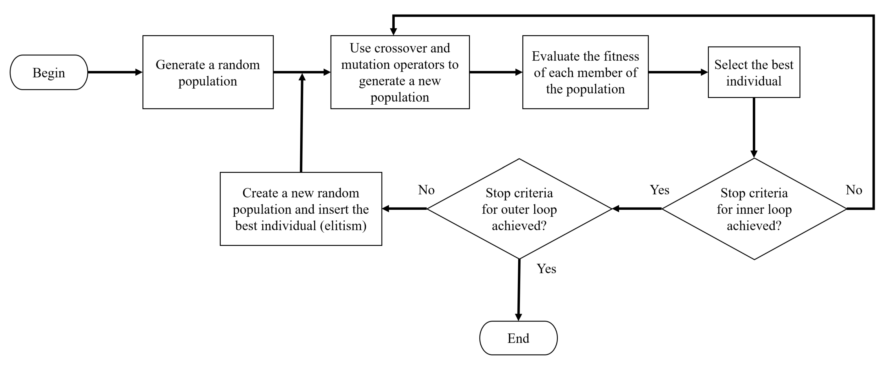
3.5. Optimization Algorithm

To solve the drum boiler startup problem, we used the micro genetic algorithm (mGA) proposed by Batres [34]. Like a traditional genetic algorithm (GA), a micro genetic algorithm (mGA) solves optimization problems with or without constraints, using small populations of individuals (solutions) based on a natural selection process that emulates biological evolution. The operation diagram of the mGA is shown in Figure 4. It consisted of an outer loop and an inner loop. The outer loop consisted of creating a new random population, transferring the best individual from the inner loop and restarting the inner loop. The amount of individuals that formed the random population was a parameter of the algorithm. The traditional genetic algorithm was used as an inner loop, consisting of the evaluation of the fitness of each member of the population, the selection of parent chromosomes, the generation of a new population by means of the crossover and mutation operations, and the separation of the best-fit individual after convergence.
In this paper, each cycle in which the inner loop was restarted is called an epoch, and every cycle of the inner loop is called a generation. The following is a detailed explanation of each of the steps in the mGA.
Generate a random population: In this step, a random group of individuals with the correspondent format was generated. It is worth mentioning that the individuals had a specific format designed for each problem. The format for this problem was a three chromosome configuration. This configuration is explained in detail later. In Figure 5, an illustration of a random generated population is shown.
Use crossover and mutation operators to generate a new population: The proposed mGA implemented two genetic operators, which are controlled by the crossover probability and the mutation probability, respectively. The crossover probability is a parameter that determines how often the crossover will be performed. Similarly, the mutation probability determines the frequency in which a mutation occurs. The crossover operator firstly selects two individuals (mom and dad individuals). These individuals are selected based on the roulette-wheel scheme [42]. Then, it selects two random genes in the chromosomes (which cannot be the first or the last gene). Then, the mom and dad individuals are split by the selected genes into three pieces. Then, from the pieces of the mom and dad individuals, two new individuals are formed (daughter and son). Son and daughter individuals have the middle part of mom and dad, respectively. Then, the left and right part of the dad individual becomes the left and right part of the daughter individual, and the left and right part of the mom individual becomes the left and right part of the son individual. In Figure 6, a graphical representation of this process is presented.
When a mutation occurs, mGA first selects one individual. This individual is also selected by the roulette-wheel scheme [42]. Then, it selects two random genes in the chromosomes (which cannot be a gene with the repetitions = 0). Then, the selected genes inside the individuals are swapped. In Figure 7, a graphical representation of this process is presented.
In Figure 8, an example is given to illustrate how the population in Figure 8 was modified using the crossover and mutation operators.
Evaluate the fitness of each member of the population: In this step, every member (individual) of the population is evaluated by means of a fitness function. The fitness function is related to the performance of the individual in terms of the objective function. In Figure 9, an illustration of the fitness result associated with each member of the population is shown.
Select the best individual: If in an iteration of the inner loop, a better individual is found, that individual is labeled as the new best individual. In Figure 10, an illustration of how the best individual is selected is shown.
Create a new random population, and insert the best individual: In this step, the best individual found in the inner loop is inserted into a new random population to be used in the outer loop. In Figure 11, an illustration of how the best individual is inserted into the new random population is shown.
In the proposed mGA algorithm, each individual is represented as an ordered list of operations. As in other genetic algorithms, each candidate solution in the population (an individual) is represented by a data structure called the chromosome. However, this paper proposes a three chromosome structure. The solution is represented by means of a three chromosome data structure. The first chromosome represents the sequence of valve actions. The second chromosome represents the action duration, and the third chromosome represents the number of times that the same action is repeated. In Appendix A, the pseudocode of the mGA is shown.
The action duration is the execution time associated with each action for which valve positions are kept unchanged. The repetition parameter shows the number of times that action is carried out. Both the valve position and the action durations are discretized. An indexed list was created containing the possible combinations between valve openings and action durations. Figure 12 shows an example of an individual represented by the proposed three chromosome scheme.

4. Case Study

The proposed approach is illustrated with a case study that focused on the generation of operation profiles and their sequences of control valve operations in a drum boiler of a thermal power plant. A simulation model was developed using the modeling and simulation environment OpenModelica [43]. Figure 13 shows the drum boiler model in the OpenModelica OMEdit graphic environment.
The drum boiler model was validated by executing the reference startup sequence published by Belkhir et al. [20] and comparing the pressure, temperature, thermal stress, heat supplied, steam flow, and steam flow regulation profiles. Figure 14 shows the reference results reported by Belkhir et al. [20] and those obtained with our model implementation, respectively. From the comparison of these profiles, it could be concluded that the simulation of the implemented model with OpenModelica was validated.
The optimization problem focused on the design of an optimal drum boiler startup profile with its corresponding control valve operation sequence. The objective was to achieve a given state in terms of steam temperature and pressure in the shortest time possible. Based on the work of Belkhir et al. [20] and Franke et al. [17], we formulated the optimization problem in terms of the drum-boiler internal pressure and the output steam mass-flow rate of the drum boiler. Therefore, the formulation of the optimization problem for the startup operating procedure can be written as follows:
Objective function:
m i n t 0 t f w 1 [ p ( t f ) p g o a l ] 2 + w 2 [ q ( t f ) q g o a l ] 2 d t
where p g o a l is the desired internal pressure, q g o a l is the desired steam mass-flow rate, and w 1 and w 2 are the weights. Based on Belkhir et al. [20], the desired internal pressure and the desired steam mass-flow rate were set to 90 bar and 185 kg/s, respectively, while w 1 and w 2 were set to 0.01 and 0.001, respectively. Model constraints must be fulfilled any time during the optimization horizon t [ t 0 , t f ] . The behavior of the system was controlled by regulating the heat flow at the input of the drum boiler and the output flow rate of the steam that was extracted from the drum boiler:
0 Q 500 M W
0 V p o s 1
where Q is the heat flow and V p o s is the valve position (in percent) of the steam output valve. In order to avoid sudden changes in the state variables, the heat flow rate ( d Q / d t ) is constrained as follows:
0 M W m i n d Q d t 25 M W m i n
In the same way, a feasible solution must be able to achieve the objective by fulfilling the process constraints. In this context, we set up inequalities constraints that determined the state variables operational range such as temperature and pressure inside the drum boiler:
p ( t f ) m i n < p ( t f ) < p ( t f ) m a x
T ( t f ) m i n < T ( t f ) < T ( t f ) m a x
These inequalities set the state variables limits and the mix quality in the drum boiler, for which it must be fulfilled that p ( t f ) m i n p a t m , p ( t f ) m a x = p n o m , T ( t f ) m i n T e c o , and T ( t f ) m a x = T n o m , where, p a t m is the atmospheric pressure, T e c o is the temperature in the economizer, p n o m is the full load nominal pressure, and T m o m is the full load nominal temperature.
Moreover, an output constraint was introduced in order to avoid large thermal stresses in the drum boiler thick wall.
10 N m m 2 σ V M 10 N m m 2
In order to include this constraint evaluation, the objective function (Equation (17)) was modified by means of a penalty function ( P F ):
P F = { if   P e n N u m 1 W 1 t f + 50 ( P e n N u m ) 2 + 50 ( P e n S t r e s s ) 2 + W 2 ( O F ) Otherwise W 1 t f + W 2 O F
where W 1 = 0.01 , W 2 = ( 1 W 1 ) , O F is the result of the objective function, P e n N u m is the amount of times the individual violates the constraint, and P e n S t r e s s is the accumulated stress violation. Both P e n N u m and P e n S t r e s s were evaluated along with the dynamic simulation from the initial state to the final state.
According to the data structure of the micro genetic algorithm, the solution is represented by three chromosomes. The first chromosome represents the sequence of valve actions. The second chromosome represents the execution time per action, and the third chromosome represents the number of times that the same action is repeated. Each element in the first chromosome is an integer that points to a combination of the valve position of the steam outlet valve and the heat flow rate. Table 1 shows the set of actions considered for this problem.
To solve the optimization problem, the micro genetic algorithm (mGA) was implemented together with an interface that connects to the drum boiler simulation model in OpenModelica. Both the algorithm and the interface were implemented in C# code.

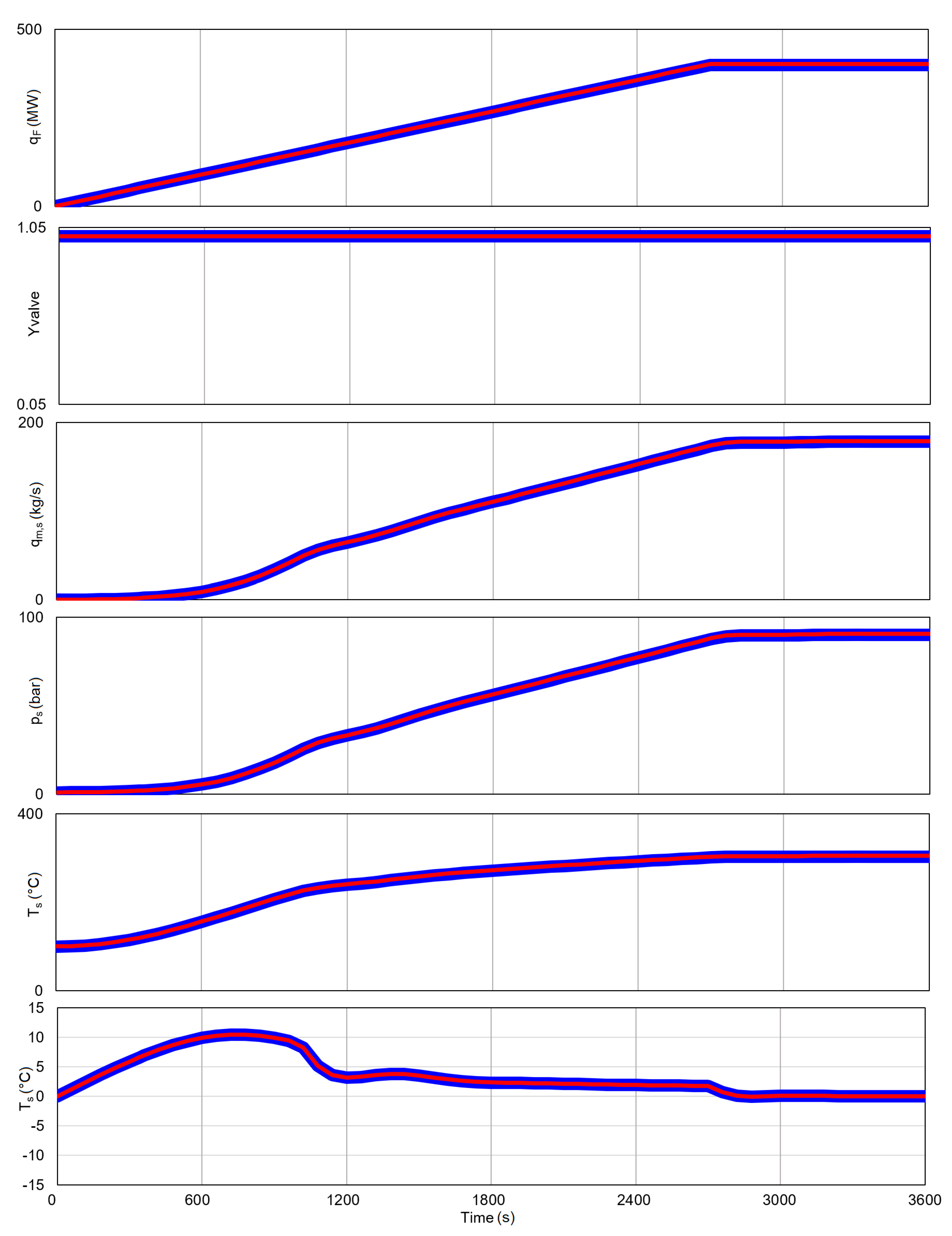
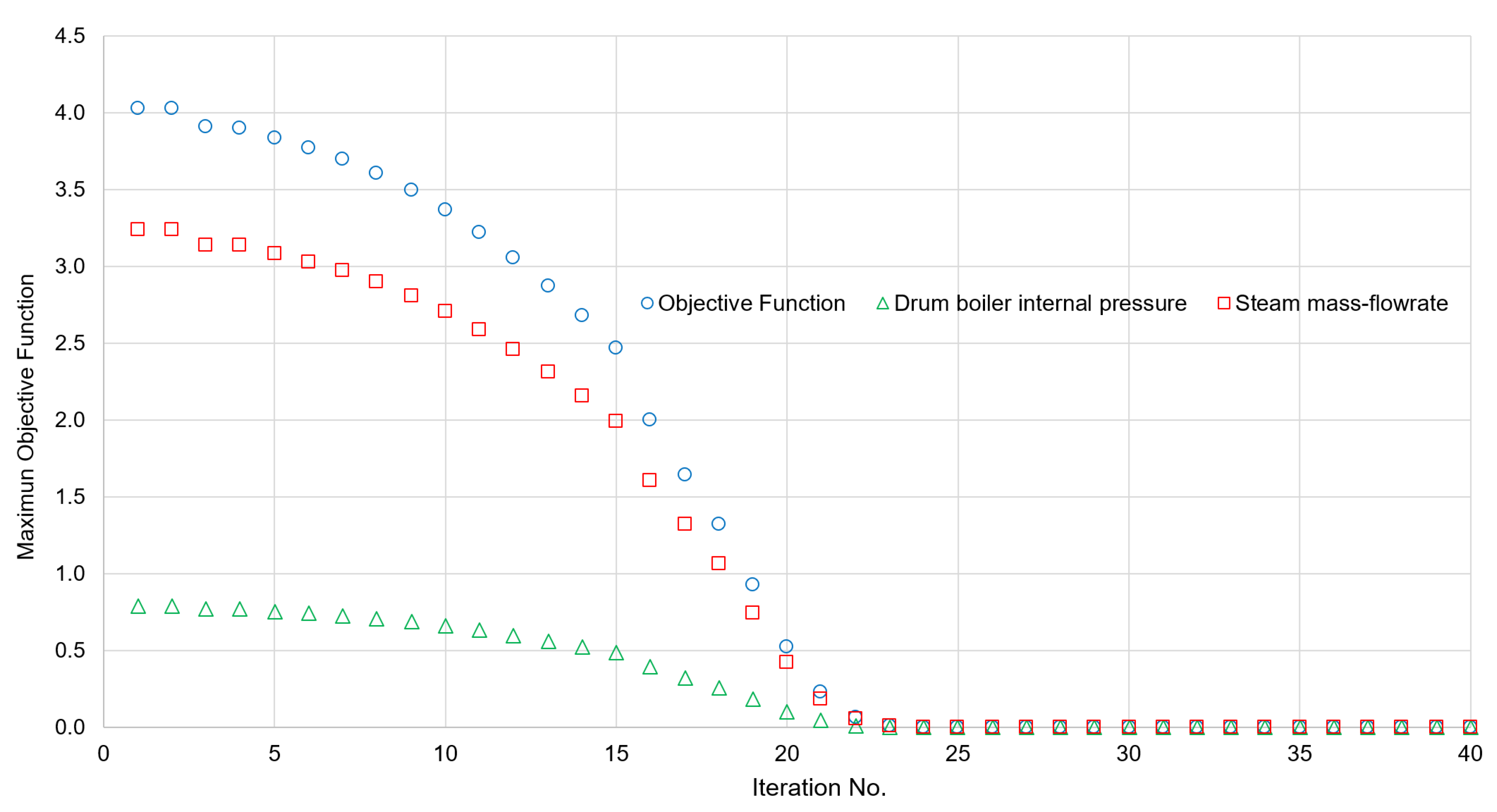
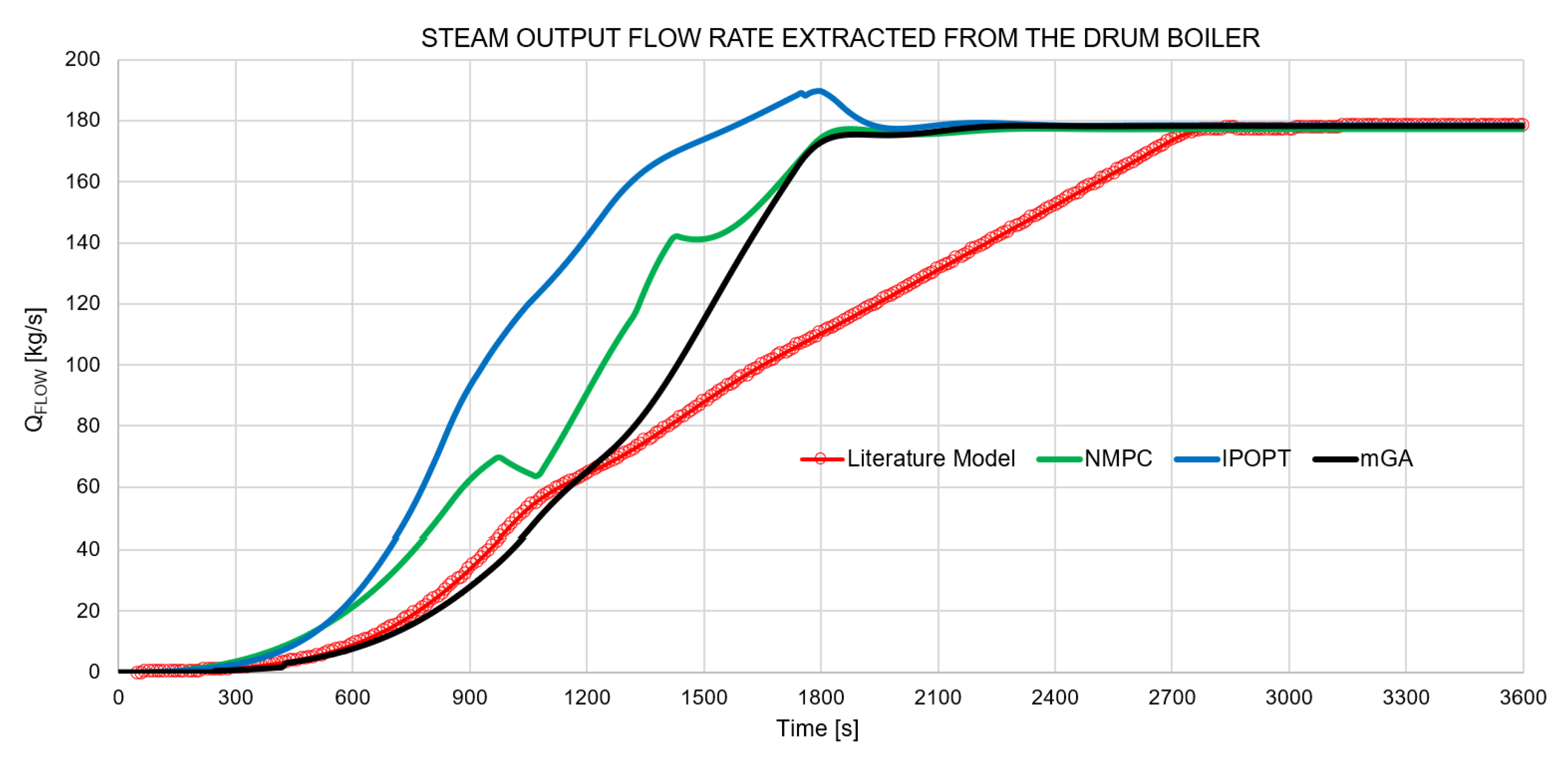
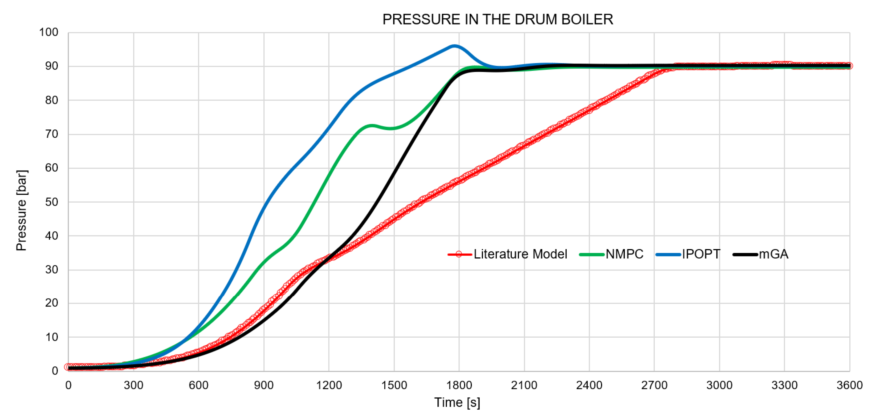
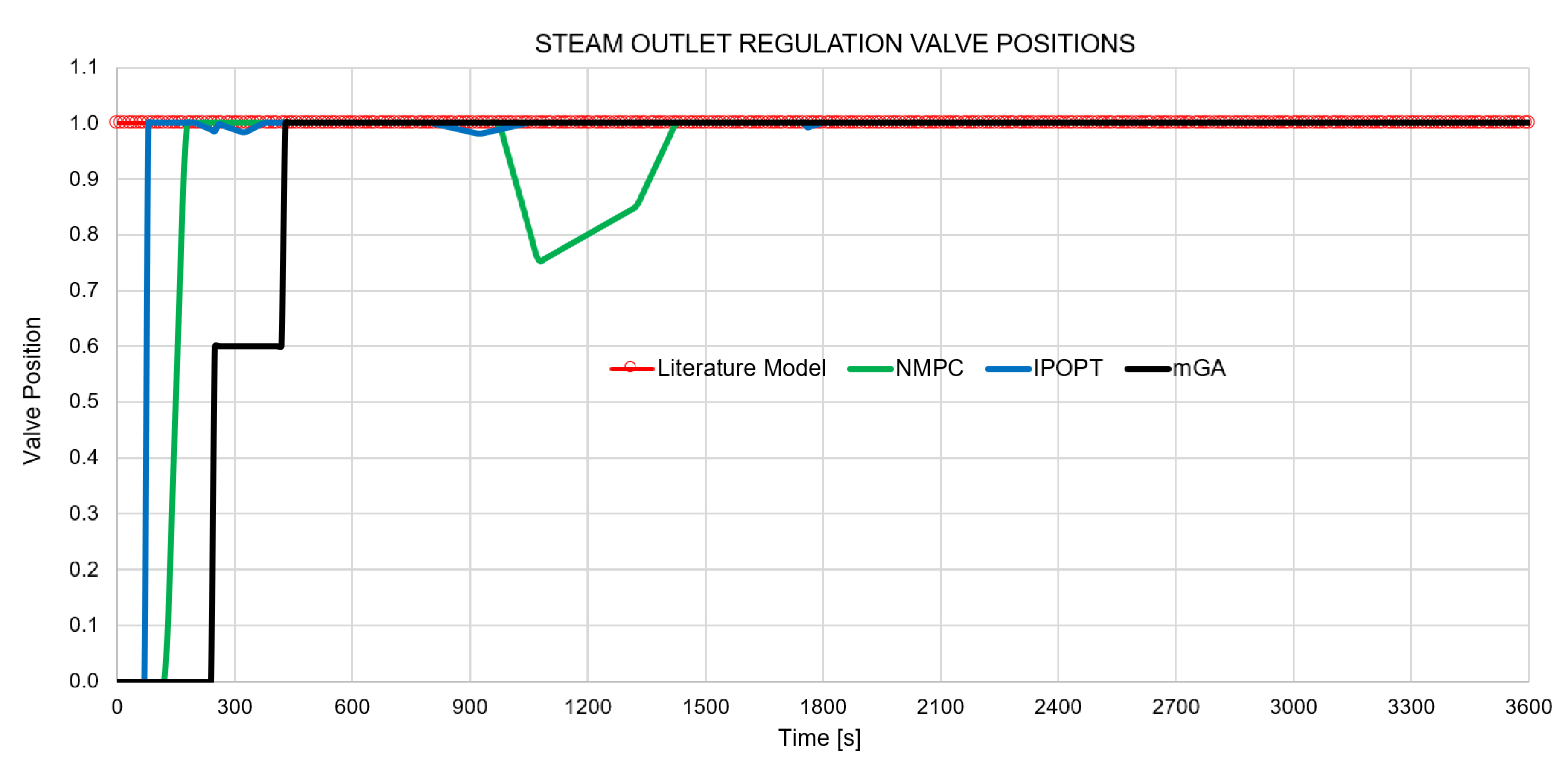
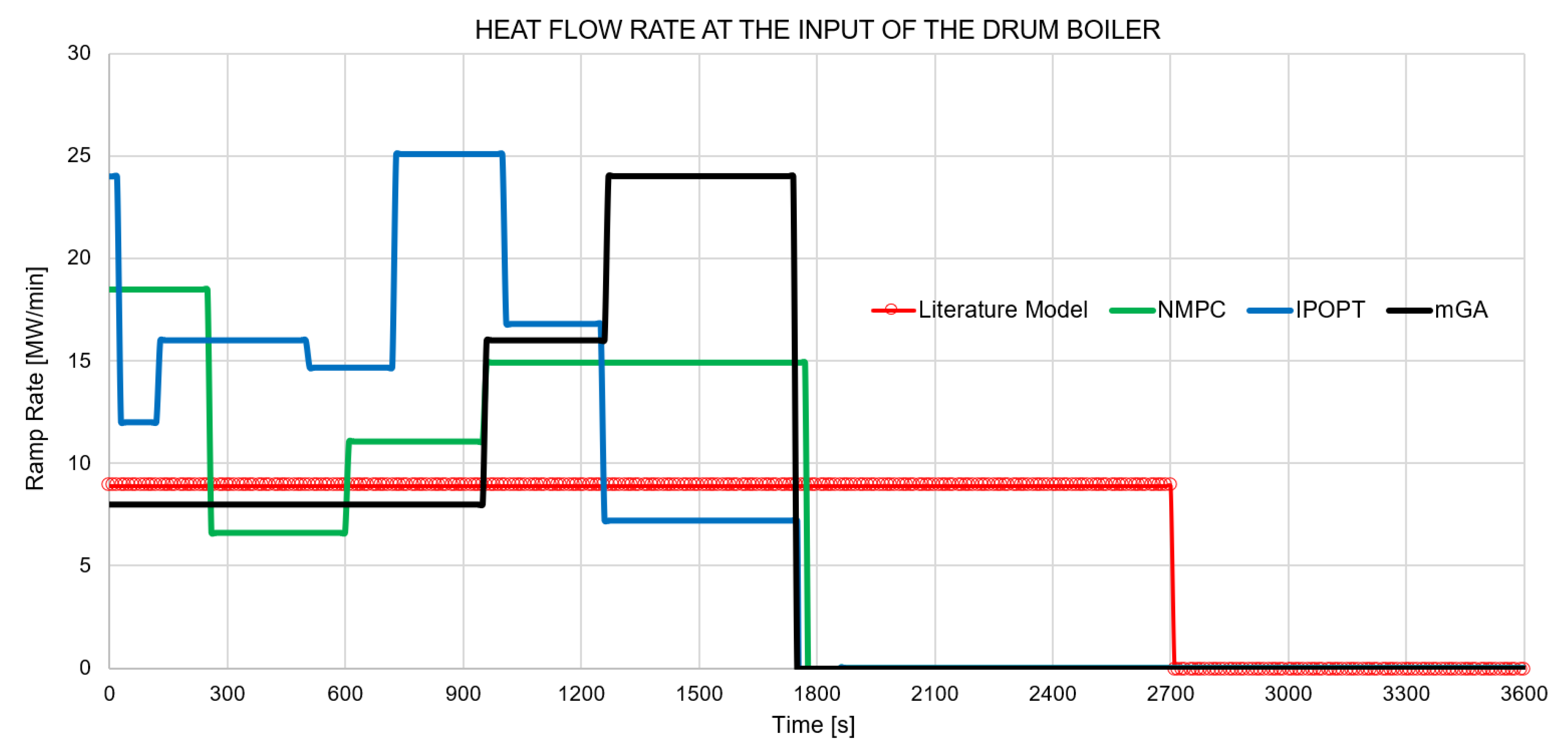
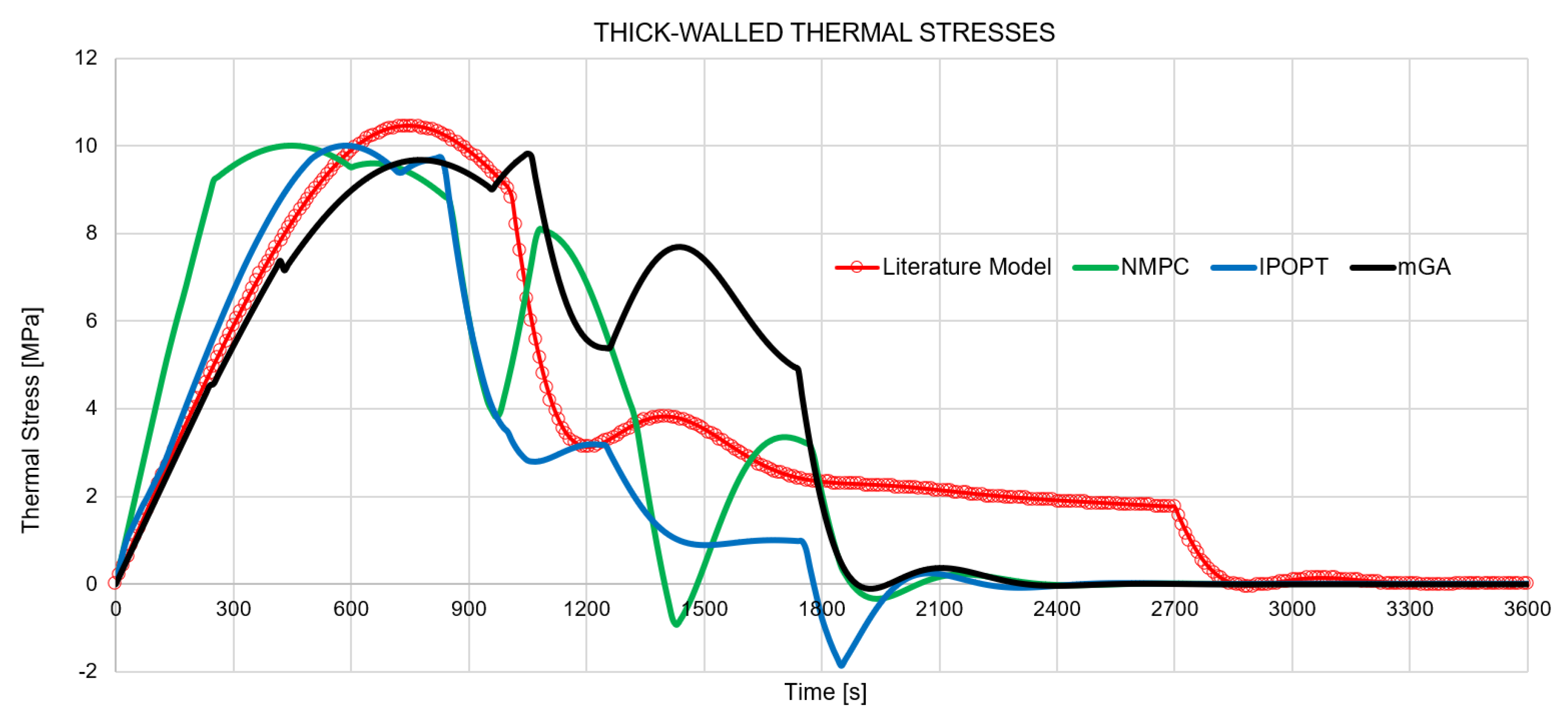
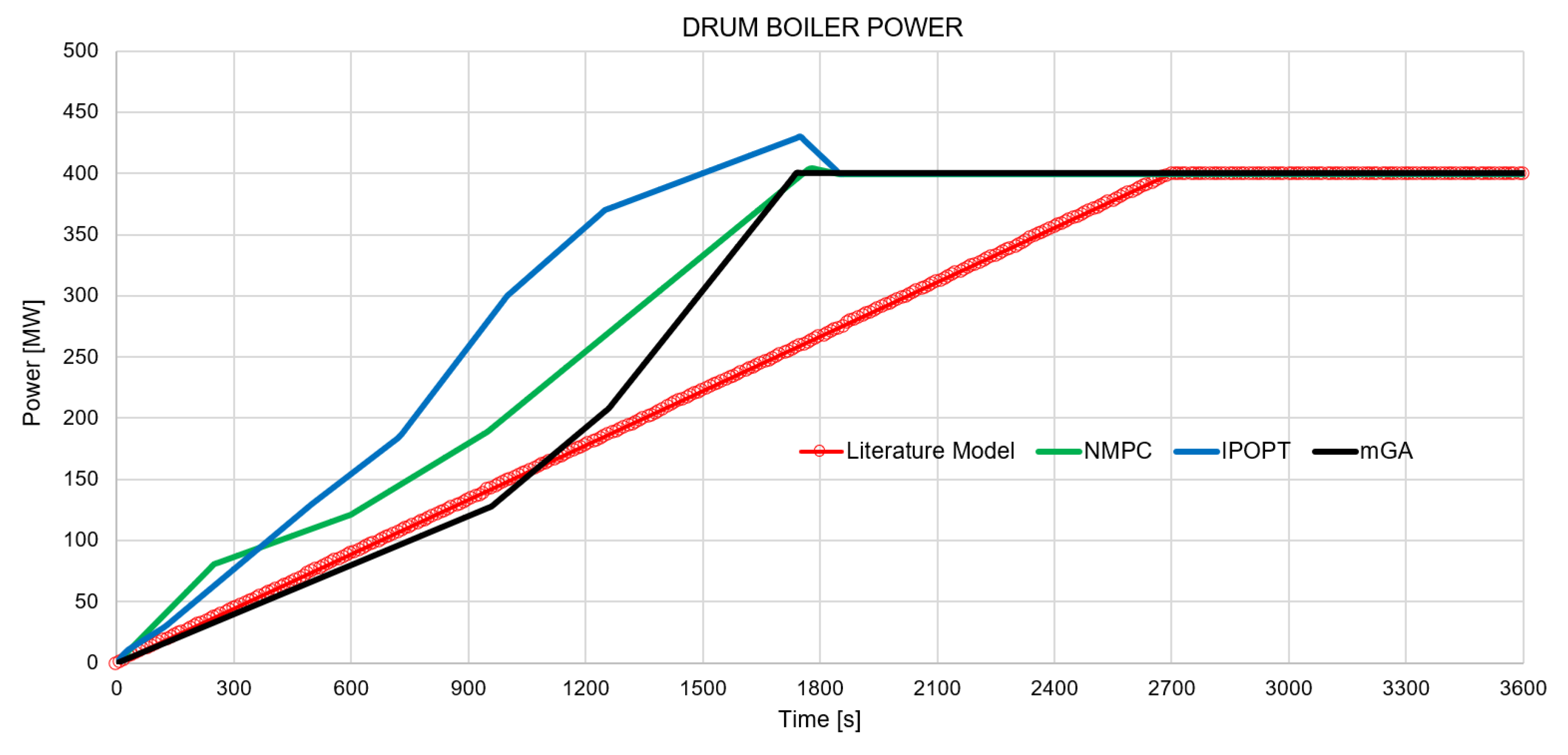
5. Experiments and Results

The experiments considered three action durations (60, 120, and 180 s) and three valve positions. As a result, eight different actions were obtained, resulting from the combination of three valve positions for the two valves (the case of both valves closed was not considered). The repetition parameter was set to take integer values from 0 to 10. The mGA probabilities used in the numerical experiments were 10% for mutation and 20% for crossover. The population of the mGA consisted of 5 individuals, and the termination criteria were set to a maximum of 40 generations and 20 epochs, respectively. Figure 15 shows the global objective function convergence for the optimization problem, as well as the goal states convergence in terms of the desired drum boiler internal pressure and the desired steam mass-flow rate.
All the experiments were carried out on a 3.4 GHz Intel Xeon E3-1245 V2 computer with 16 GB of RAM, running Windows 10 pro.
Figure 16, Figure 17, Figure 18, Figure 19, Figure 20 and Figure 21 show the comparison of the results of this research with those obtained by [17,20]. In these figures, red lines correspond to the reference model, while the green and blue lines are the results presented by [17,20], who solved the optimization problem using a nonlinear model predictive control (NMPC) and the interior point method (IPOPT), respectively. The black lines correspond to the optimized drum boiler startup profile according to the dynamic optimization framework proposed in this research.
Figure 16 and Figure 17 show the comparison of the operating profiles. Figure 18 and Figure 19 show the operation of the valves that control the heat supplied to the system and the steam flow that is sent to the power train. Finally, the system structural constraint and the maximum power generated are shown in Figure 20 and Figure 21.
For both state variables (Figure 16 and Figure 17), it can be observed that the dynamic optimization framework can achieve the desired startup goal in less time than the reference model and with a startup time of the same order of magnitude as the optimized profiles reported by [17,20], with a small number of iterations in the mGA optimization algorithm, as shown in Figure 15. Likewise, the proposed framework was capable of generating the sequence of valve operations of the steam regulation valve and the heat flow supplied to the system, which were the main controlled process variables that determine the efficiency of the steam generation process in a thermal power plant.
As shown in Figure 18, in the reference profile, the saturated steam regulation valve that supplied energy to the powertrain remained fully open during the entire startup process, while for the optimized profile presented by [17], the steam flow regulation was carried out during the period of 1000 to 1400 s, displaying large instabilities in the state variables. Regarding the profile optimization reported by [20], the steam valve regulation was minimal, since the valve changes ranged from fully open to 98% and 99% open, with instabilities in the state variables. In contrast, the proposed dynamic optimization framework suggests that the steam flow control valve should be operated sequentially and gradually in order to achieve the goal state efficiently, generating stable and continuous profiles for the state variables.
In the same way, the heat supply for the reference profile was carried out in a continuous and constant way from the beginning of the process until the system reached the goal state. For the profiles proposed by [17,20], the heat supply was achieved by oscillating and intermittent patterns. In the case of the proposed framework, the heat supply is continuously applied and gradually increased until the goal state reached. The heat supply profiles of the system for all startup processes evaluated in this paper are shown in Figure 19.
Finally, to avoid hazardous scenarios in which the proposed profiles could result in a decrease of useful life and the structural integrity of the thick-walled components constraint must be monitored. In this context, in the case of the optimized profiles presented by [17,20], a decrease in the useful life of the thick-walled component’s is expected since more alternating tension and compression stresses occur in comparison to the reference profile [20]. The thermal stress profile generated by the proposed dynamic optimization framework has comparable pattern, shape, and magnitude as in the reference profile, thus useful life of the thick-walled components is similar.

6. Conclusions and Future Work

An approach to managing the thermal power plant’s flexible operation based on the steam generation process optimization was presented. A strategy at the process level, as a first step in the operational optimization of the entire power plant, was used. The case study focused on the drum boiler since it was considered the most critical element in the steam generation process. This paper proposed a dynamic optimization framework in order to find the optimum valve sequences that minimized the startup time.
The proposed framework had four main components: optimizer, solution generator, simulator, and evaluator. The Optimizer ran the optimization algorithm and requested solutions from the Solution Generator. The Solution Generator proposed new solutions based on previous ones and requested the Simulator to solve the simulation model. After each simulation, the Evaluator calculated the objective function and evaluated the constraints.
In the proposed approach, the problem of finding the optimal sequences of control valves that minimized the time needed to take the drum boiler from an initial state to a goal state was formulated as a dynamic optimization problem. To solve the optimization problem, the micro genetic algorithm (mGA) was implemented together with an interface that connected it to the drum boiler simulation model in OpenModelica. The drum boiler simulation model was validated against the data available in the literature. The proposed optimization algorithm was characterized by the use of variable length chromosomes and the use of small population sizes.
The dynamic optimization framework took 18,000 s to find the optimal operation sequence, considering the mGA optimization algorithm stop criteria and that each drum boiler dynamic simulation was carried out in 22.5 s on average. Likewise, numeric results showed that with the optimal operation sequence found with the proposed approach, the steam production goal was reached in 35% less time compared to the baseline startup strategy. As future work, we will investigate an optimization approach based on exergy or entropy. Likewise, this approach will be tested using a gas turbine combined heat and power system coupled with mGA.
Compared to gradient based methods, genetic algorithms are easy to implement, have tolerance of noise in the objective function and usually find a global optimum. However, genetic algorithms have a slow convergence and need a termination criterion, which does not guarantee that a global optimum is found every time the algorithm is executed.
In summary, the proposed dynamic optimization framework aimed at designing the operation sequence that minimized the drum boiler startup times to satisfy the steam demand required by the power plant, identifying the corresponding control actions and their sequence in order to design in an integral way the optimal operating procedure, without compromising the structural integrity of critical components. Likewise, a scalable tool was developed focused on being implemented in more complex processes and applications, whose applications involved advanced dynamic simulation and optimization techniques aimed at improving the designs of the operating procedures.

Author Contributions

All the authors contributed to this research. The following are the specific contributions per author: E.R.-T., conceptualization, formal analysis, investigation, methodology, validation, and writing, original draft; M.A.Z.-G., formal analysis, software, investigation, and writing, original draft; A.C.-A., supervision, validation, and writing, review and editing; R.B., methodology, supervision, writing, review and editing, project administration, and funding acquisition. All authors read and agreed to the published version of the manuscript.

Funding

This research was funded by the CONACYT SENER Fund for Energy Sustainability Grant Number S0019201401.

Acknowledgments

This research is a result of the Project 266632 “Laboratorio Binacional para la Gestión Inteligente de la Sustentabilidad Energética y la Formación Tecnológica” (“Bi-National Laboratory on Smart Sustainable Energy Management and Technology Training”), funded by the CONACYT SENER Fund for Energy Sustainability (Agreement: S0019201401).

Conflicts of Interest

The authors declare no conflict of interest.

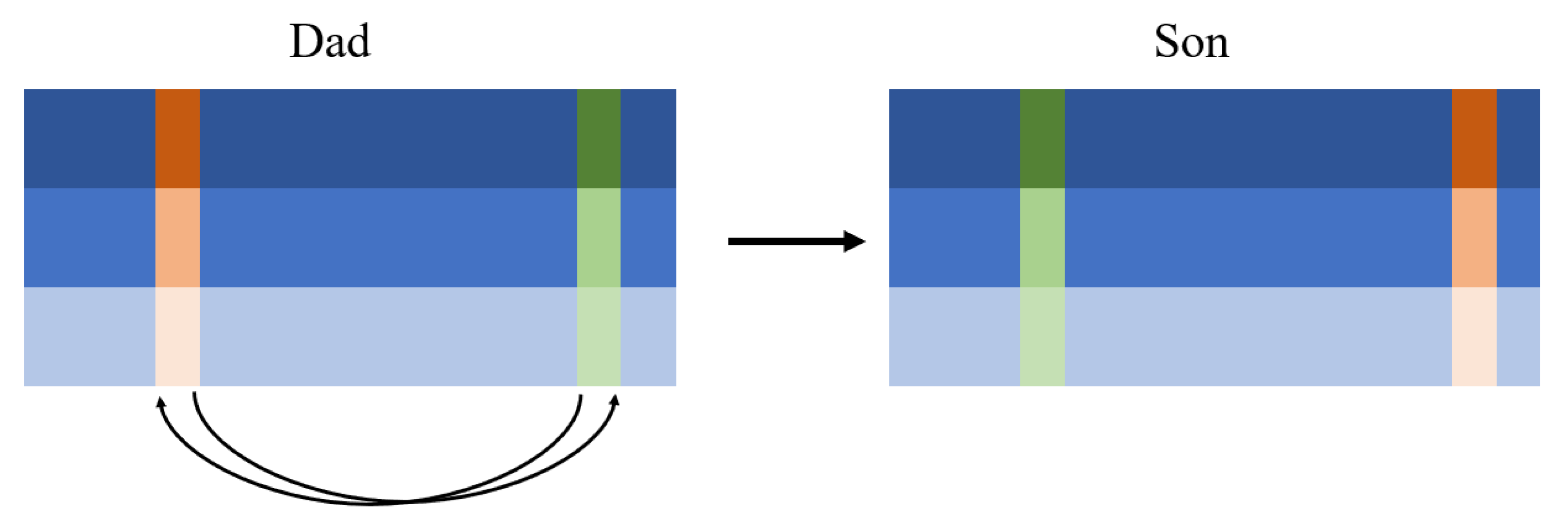
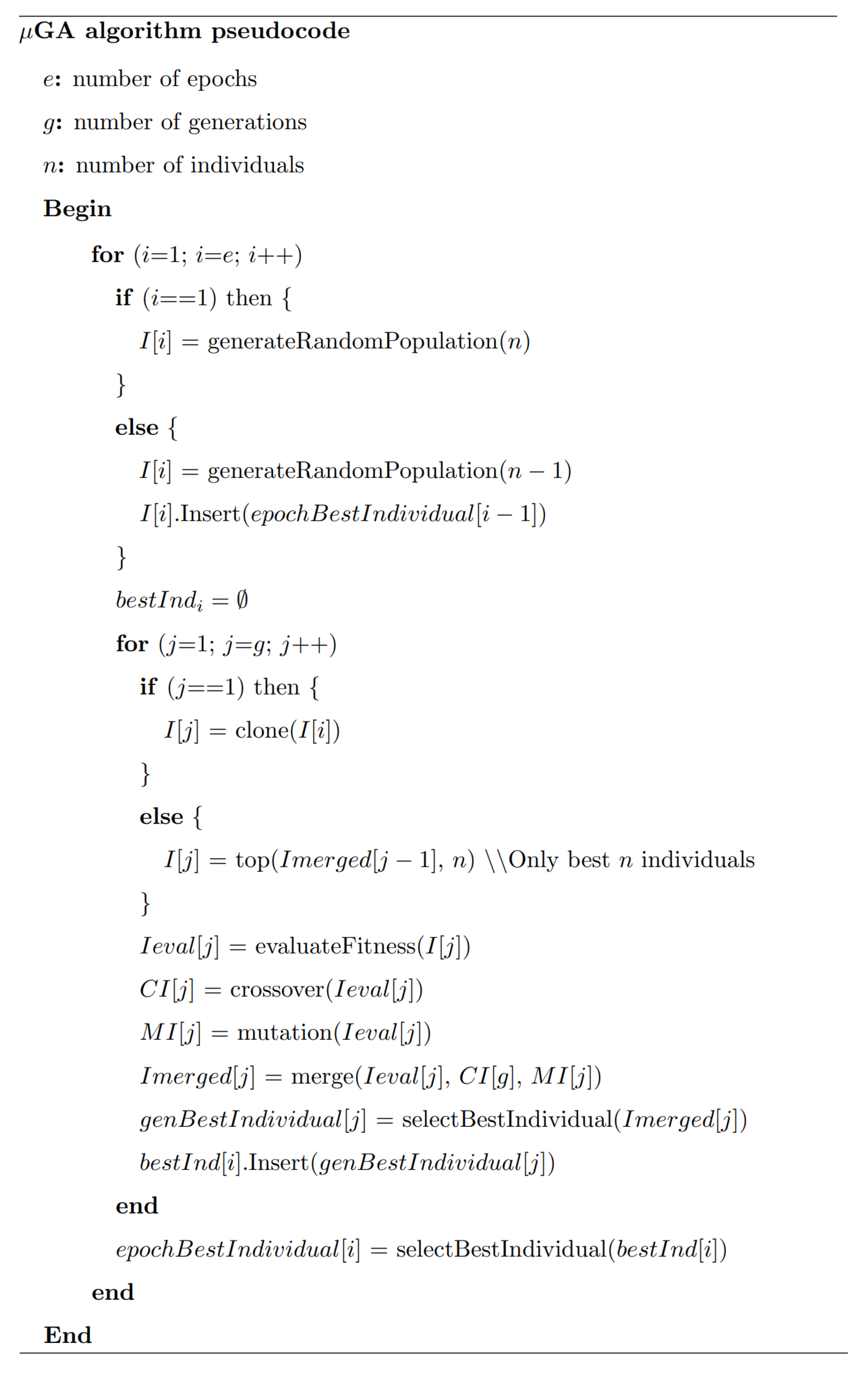
Appendix A. The Micro Genetic Algorithm

The pseudocode of the micro genetic algorithm is shown as follows.
Figure A1. The pseudocode of the micro genetic algorithm.
Energies 13 00677 g0a1

References

  1. Kirby, B. Ancillary services: Technical and commercial insights. Retrieved Oct. 2007, 4, 2012. [Google Scholar]
  2. Cochran, J.; Miller, M.; Zinaman, O.; Milligan, M.; Arent, D.; Palmintier, B.; O’Malley, M.; Mueller, S.; Lannoye, E.; Tuohy, A.; et al. Flexibility in 21st Century Power Systems; Technical Report; National Renewable Energy Lab. (NREL): Golden, CO, USA, 2014.
  3. Gonzalez-Salazar, M.A.; Kirsten, T.; Prchlik, L. Review of the operational flexibility and emissions of gas-and coal-fired power plants in a future with growing renewables. Renew. Sustain. Energy Rev. 2018, 82, 1497–1513. [Google Scholar] [CrossRef]
  4. Taibi, E.; Nikolakakis, T.; Gutierrez, L.; Fernandez, C.; Kiviluoma, J.; Rissanen, S.; Lindroos, T.J. Power System Flexibility for the Energy Transition: Part 1, Overview for Policy Makers; IRENA: Abu Dhabi, UAE, 2018. [Google Scholar]
  5. Elzinga, D.; Baritaud, M.; Bennett, S.; Burnard, K.; Pales, A.; Philibert, C.; Cuenot, F.; D’Ambrosio, D.; Dulac, J.; Heinen, S.; et al. Energy Technology Perspectives 2014: Harnessing electricity’s Potential; International Energy Agency (IEA): Paris, France, 2014. [Google Scholar]
  6. Lott, M.; Kim, S. Technology Roadmap: Energy Storage; International Energy Agency: Paris, France, 2014. [Google Scholar]
  7. von Roon, S.; Huber, M. Modeling spot market pricing with the residual load. In Proceedings of the Enerday-5th Conference on Energy Economics and Technology, Dresden, Germany, 16 April 2010. [Google Scholar]
  8. Glensk, B.; Rosen, C.; Schiavo, R.B.; Rabiee, S.; Madlener, R.; De Doncker, R. Economic and Technical Evaluation of Enhancing the Flexibility of Conventional Power Plants. Available online: https://d-nb.info/1159380031/34 (accessed on 14 December 2019).
  9. Kubik, M.; Coker, P.J.; Barlow, J.F. Increasing thermal plant flexibility in a high renewables power system. Appl. Energy 2015, 154, 102–111. [Google Scholar] [CrossRef]
  10. Hentschel, J.; Spliethoff, H. A parametric approach for the valuation of power plant flexibility options. Energy Rep. 2016, 2, 40–47. [Google Scholar] [CrossRef] [Green Version]
  11. Casella, F.; Farina, M.; Righetti, F.; Faille, D.; Tica, A.; Gueguen, H.; Scattolini, R.; Davelaar, F.; Dumur, D. An optimization procedure of the start-up of combined cycle power plants. IFAC Proc. Vol. 2011, 44, 7043–7048. [Google Scholar] [CrossRef] [Green Version]
  12. Almodarra, S.; Alabdulkarem, A. Efficiency Optimization of Four Gas Turbine Power Plant Configurations. In ASME 2016 Power Conference collocated with the ASME 2016 10th International Conference on Energy Sustainability and the ASME 2016 14th International Conference on Fuel Cell Science, Engineering and Technology; American Society of Mechanical Engineers Digital Collection, 2016; Available online: https://asmedigitalcollection.asme.org/POWER/proceedings-abstract/POWER2016/50213/V001T02A002/365710 (accessed on 14 December 2019).
  13. Anisimov, A.; Klub, M.; Sargsyan, K.; Eritsyan, S.K.; Petrosyan, G.; Avtandilyan, A.; Gevorgyan, A. Optimization of Start-Up of a Fully Fired Combined-Cycle Plant with GT13E2 Gas Turbine. Power Technol. Eng. 2016, 49, 359–364. [Google Scholar] [CrossRef]
  14. Rossi, I.; Sorce, A.; Traverso, A. Gas turbine combined cycle start-up and stress evaluation: A simplified dynamic approach. Appl. Energy 2017, 190, 880–890. [Google Scholar] [CrossRef]
  15. Ji, D.-M.; Sun, J.-Q.; Sun, Q.; Guo, H.-C.; Ren, J.-X.; Zhu, Q.-J. Optimization of start-up scheduling and life assessment for a steam turbine. Energy 2018, 160, 19–32. [Google Scholar]
  16. Liu, Z.; Karimi, I. Simulation and optimization of a combined cycle gas turbine power plant for part-load operation. Chem. Eng. Res. Des. 2018, 131, 29–40. [Google Scholar] [CrossRef]
  17. Franke, R.; Rode, M.; Krüger, K. On-line optimization of drum boiler startup. In Proceedings of the 3rd International Modelica Conference, Linköping, Sweden, 3–4 November 2003; Volume 3. [Google Scholar]
  18. El-Guindy, A.; Rünzi, S.; Michels, K. Optimizing drum-boiler water level control performance: A practical approach. In Proceedings of the 2014 IEEE Conference on Control Applications (CCA), Juan Les Antibes, France, 8–10 October 2014; pp. 1675–1680. [Google Scholar]
  19. Elshafei, M.; Habib, M.A.; Al-Zaharnah, I.; Nemitallah, M.A. Boilers optimal control for maximum load change rate. J. Energy Resour. Technol. 2014, 136, 031301. [Google Scholar] [CrossRef]
  20. Belkhir, F.; Cabo, D.K.; Feigner, F.; Frey, G. Optimal startup control of a steam power plant using the Jmodelica Platform. IFAC-PapersOnLine 2015, 48, 204–209. [Google Scholar] [CrossRef]
  21. Zhang, T.; Zhao, Z.; Li, Y.; Zhu, X. The simulation of start-up of natural circulation boiler based on the Astrom-Bell model. In AIP Conference Proceedings; AIP Publishing: Melville, NY, USA, 2017. [Google Scholar]
  22. Taler, J.; Dzierwa, P.; Taler, D.; Harchut, P. Optimization of the boiler start-up taking into account thermal stresses. Energy 2015, 92, 160–170. [Google Scholar] [CrossRef]
  23. Åström, K.J.; Eklund, K. A simplified non-linear model of a drum boiler-turbine unit. Int. J. Control 1972, 16, 145–169. [Google Scholar] [CrossRef] [Green Version]
  24. Åström, K.J.; Bell, R.D. Simple drum-boiler models. In Power Systems: Modelling and Control Applications; Elsevier: Amsterdam, The Netherlands, 1989; pp. 123–127. [Google Scholar]
  25. Peet, W.; Leung, T. Development and Application of a Dynamic Simulation Model for a Drum Type Boiler with Turbine Bypass System. Available online: http://citeseerx.ist.psu.edu/viewdoc/summary?doi=10.1.1.126.1142 (accessed on 14 December 2019).
  26. Bell, R.D.; Åström, K.J. A fourth order non-linear model for drum-boiler dynamics. IFAC Proc. Vol. 1996, 29, 6873–6878. [Google Scholar] [CrossRef]
  27. Flynn, M.; O’Malley, M. A drum boiler model for long term power system dynamic simulation. IEEE Trans. Power Syst. 1999, 14, 209–217. [Google Scholar] [CrossRef]
  28. Åström, K.J.; Bell, R.D. Drum-boiler dynamics. Automatica 2000, 36, 363–378. [Google Scholar] [CrossRef]
  29. Wen, C.; Ydstie, B.E. Passivity based control of drum boiler. In Proceedings of the 2009 American Control Conference, St. Louis, MO, USA, 10–12 June 2009; pp. 1586–1591. [Google Scholar]
  30. Elmqvist, H.; Tummescheit, H.; Otter, M. Modeling of thermo-fluid systems–Modelica. Media and Modelica. Fluid. In Proceedings of the 3rd International Modelica Conference, Linköping, Sweden, 3–4 November 2003. [Google Scholar]
  31. Krüger, K.; Franke, R.; Rode, M. Optimization of boiler start-up using a nonlinear boiler model and hard constraints. Energy 2004, 29, 2239–2251. [Google Scholar] [CrossRef]
  32. Li, B.; Chen, T.; Yang, D. DBSSP—A computer program for simulation of controlled circulation boiler and natural circulation boiler start up behavior. Energy Convers. Manag. 2005, 46, 533–549. [Google Scholar] [CrossRef]
  33. Zhu, G.Q.; Yang, L.; Cheng, G. Dynamic Optimization of Ship Boiler Startup Based on Modelica and JModelica. org. In Applied Mechanics and Materials; Trans Tech Publications: Zurich, Switzerland, 2014; Volume 662, pp. 191–195. [Google Scholar]
  34. Batres, R. Generation of operating procedures for a mixing tank with a micro genetic algorithm. Comput. Chem. Eng. 2013, 57, 112–121. [Google Scholar] [CrossRef]
  35. Pelusi, D.; Mascella, R.; Tallini, L.; Vazquez, L.; Diaz, D. Control of Drum Boiler dynamics via an optimized fuzzy controller. Int. J. Simul. Syst. Sci. Technol. 2016, 17, 1–7. [Google Scholar]
  36. Krishnan, P.H.; Prathyusha, S. Optimization of Main Boiler Parameters Using Soft Computing Techniques. Available online: https://ijret.org/volumes/2014v03/i19/IJRET20140319099.pdf (accessed on 14 December 2019).
  37. Bartl, M.; Li, P.; Biegler, L.T. Improvement of state profile accuracy in nonlinear dynamic optimization with the quasi-sequential approach. AIChE J. 2011, 57, 2185–2197. [Google Scholar] [CrossRef]
  38. Hong, W.; Wang, S.; Li, P.; Wozny, G.; Biegler, L.T. A quasi-sequential approach to large-scale dynamic optimization problems. AIChE J. 2006, 52, 255–268. [Google Scholar] [CrossRef]
  39. Zingg, D.W.; Nemec, M.; Pulliam, T.H. A comparative evaluation of genetic and gradient-based algorithms applied to aerodynamic optimization. Eur. J. Comput. Mech./Rev. Eur. Méc. Numér. 2008, 17, 103–126. [Google Scholar] [CrossRef] [Green Version]
  40. Cannon, G. Process Technology Equipment; Pearson Education, Incorporated: London, UK, 2019. [Google Scholar]
  41. Mirandola, A.; Stoppato, A.; Casto, E.L. Evaluation of the effects of the operation strategy of a steam power plant on the residual life of its devices. Energy 2010, 35, 1024–1032. [Google Scholar] [CrossRef]
  42. Davis, L. Handbook of Genetic Algorithms; Van Nostrand Reinhold: New York, NY, USA, 1991. [Google Scholar]
  43. Fritzson, P.; Pop, A.; Asghar, A.; Bachmann, B.; Braun, W.; Braun, R.; Buffoni, L.; Casella, F.; Castro, R.; Danós, A.; et al. The OpenModelica Integrated Modeling, Simulation, and Optimization Environment. In Proceedings of The American Modelica Conference 2018, Cambridge, MA, USA, 9–10 October 2019; Linköping University Electronic Press: Linköping, Sweden, 2019; pp. 206–219. [Google Scholar]
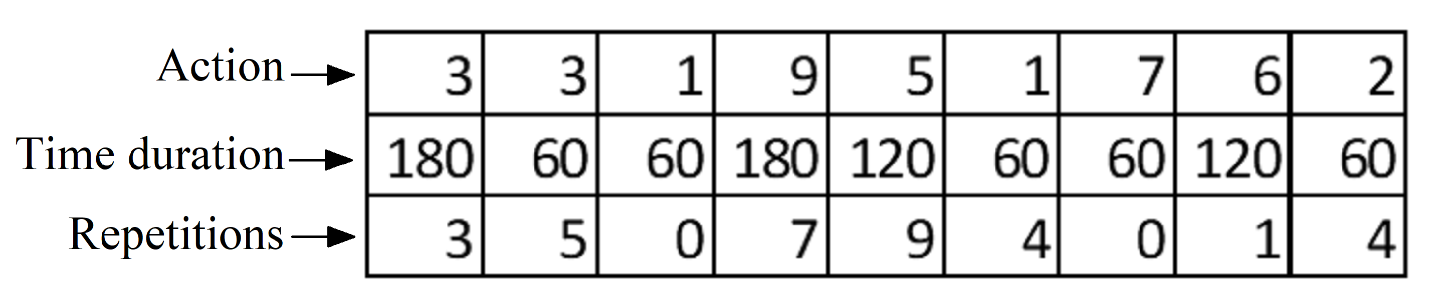
Figure 1. A drum boiler’s basic configuration.
Energies 13 00677 g001
Figure 2. A 3D model of a typical drum boiler configuration. mGA, micro genetic optimization algorithm.
Energies 13 00677 g002
Figure 3. Implementation of the framework.
Energies 13 00677 g003
Figure 4. Operation diagram of the mGA.
Energies 13 00677 g004
Figure 5. Example of a random population of four individuals.
Energies 13 00677 g005
Figure 6. Graphical representation of the crossovergenetic operator in the mGA.
Energies 13 00677 g006
Figure 7. Graphical representation of the mutation genetic operator in the mGA.
Energies 13 00677 g007
Figure 8. The new population after the crossover and mutation operators.
Energies 13 00677 g008
Figure 9. An example of the fitness associated with each member of the population.
Energies 13 00677 g009
Figure 10. An example of the selection of the best individual of the population.
Energies 13 00677 g010
Figure 11. An example of the insertion of the best individual into the new random population.
Energies 13 00677 g011
Figure 12. Example of an individual represented by three chromosomes.
Energies 13 00677 g012
Figure 13. Drum boiler simulator: OpenModelica.
Energies 13 00677 g013
Figure 14. Drum boiler simulation results. Belkhir et al. [20] (blue line); proposed approach (red line).
Energies 13 00677 g014
Figure 15. mGA objective function convergence.
Energies 13 00677 g015
Figure 16. Results comparison between the curves of the operating reference profile available in the literature (red line), the optimized profiles reported by [17] (green line) and [20] (blue line), and the proposed approach (black line) for the output flow rate of the steam that exits from the drum boiler. NMPC, nonlinear model predictive control; IPOPT, interior point optimizer algorithm.
Energies 13 00677 g016
Figure 17. Results comparison between the curves of the operating reference profile available in the literature (red line), the optimized profiles reported by [17] (green line) and [20] (blue line), and the proposed approach (black line) for the pressure in the drum boiler.
Energies 13 00677 g017
Figure 18. Results comparison between the curves of the operating reference profile available in the literature (red line), the optimized profiles reported by [17] (green line) and [20] (blue line), and the proposed approach (black line) for the steam regulator valve position.
Energies 13 00677 g018
Figure 19. Results comparison between the curves of the operating reference profile available in the literature (red line), the optimized profiles reported by [17] (green line) and [20] (blue line), and the proposed approach (black line) for the heat flow supplied to the system.
Energies 13 00677 g019
Figure 20. Results comparison between the curves of the operating reference profile available in the literature (red line), the optimized profiles reported by [17] (green line) and [20] (blue line), and the proposed approach (black line) for the thick-walled von Mises stresses.
Energies 13 00677 g020
Figure 21. Results comparison between the curves of the operating reference profile available in the literature (red line), the optimized profiles reported by [17] (green line) and [20] (blue line), and the proposed approach (black line) for the power generated.
Energies 13 00677 g021
Table 1. Combinations of the heat and steam valve of each action.
Action dQ / dt V pos
180.0
280.6
381.0
4160.0
5160.6
6161.0
7240.0
8240.6
9241.0

