A Novel Servovalve Pilot Stage Actuated by a Piezo-electric Ring Bender: A Numerical and Experimental Analysis


 ,
, 


Abstract
1. Introduction
- (1)
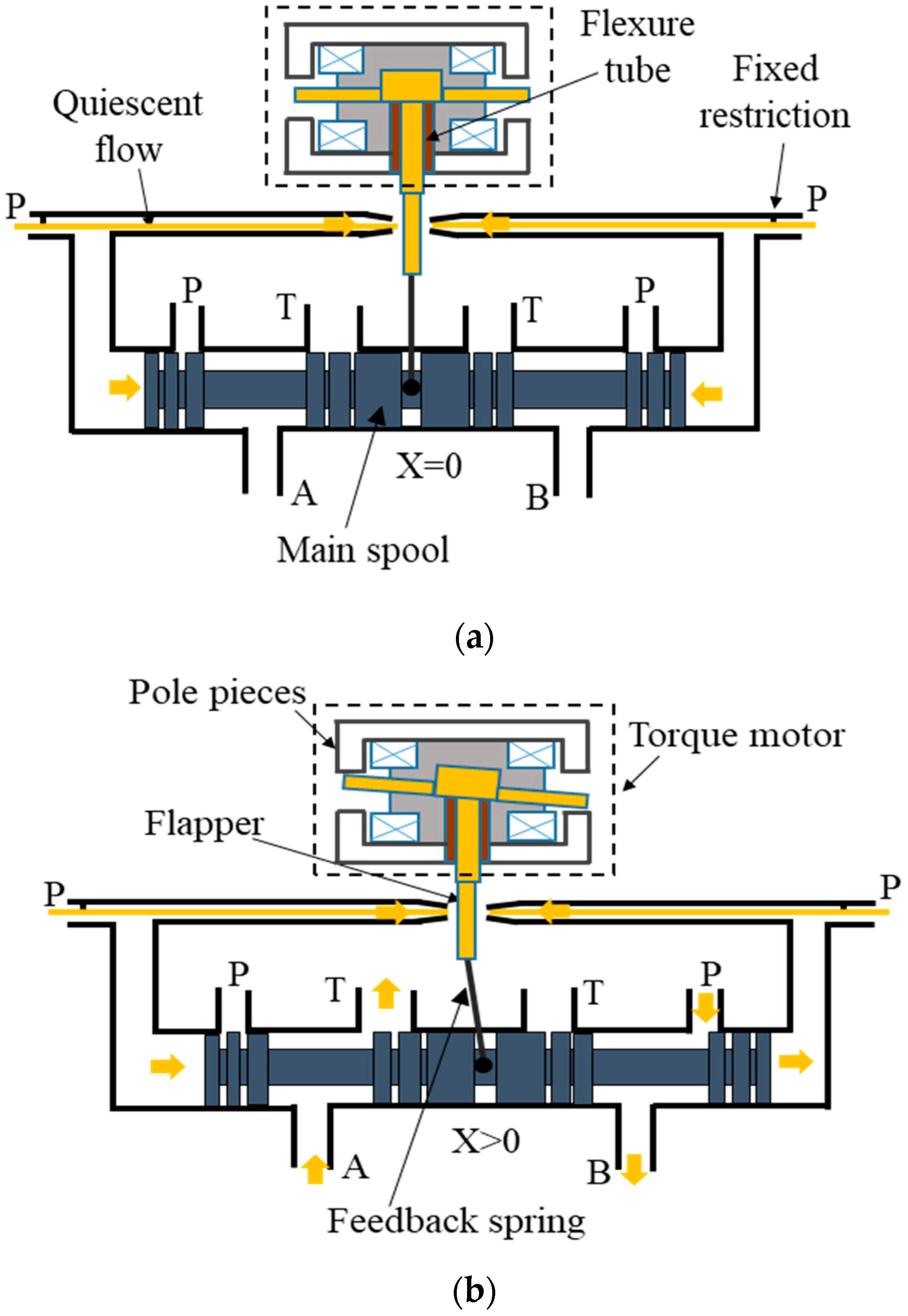
- The pilot stage requires a quiescent flow rate to work, to be referred to as the internal leakage of the pilot stage (note that the overall internal leakage is the sum of this contribution and a second contribution given by the internal leakage in the main stage). Although it is small compared to the nominal flow rate of a valve, the internal leakage in the pilot stage is continuous and constant regardless of the opening degree of the main stage, thus causing unwanted power consumption during operation [1,2].
- (2)
- The electromagnetic torque motor assembly is also a major issue associated with these valves because it is composed of many sensitive mechanical and electrical parts that penalise simplicity, set-up, duration of manufacture and manufacturing costs. Of these components, the flexure tube, used to support the flapper while separating the torque motor from the hydraulic fluid, is the most critical. Indeed, it needs to be manufactured very accurately to ensure the stiffness required [1,2]. Moreover, the flapper-flexure tube system is very sensitive to vibration, and a valve may experience fatigue failure of the flexure tube due to excessive bending under vibration, in addition to the fact that the oscillations of the flapper caused by external noise may result in a change of the valve output [1,2].
2. Materials and Methods
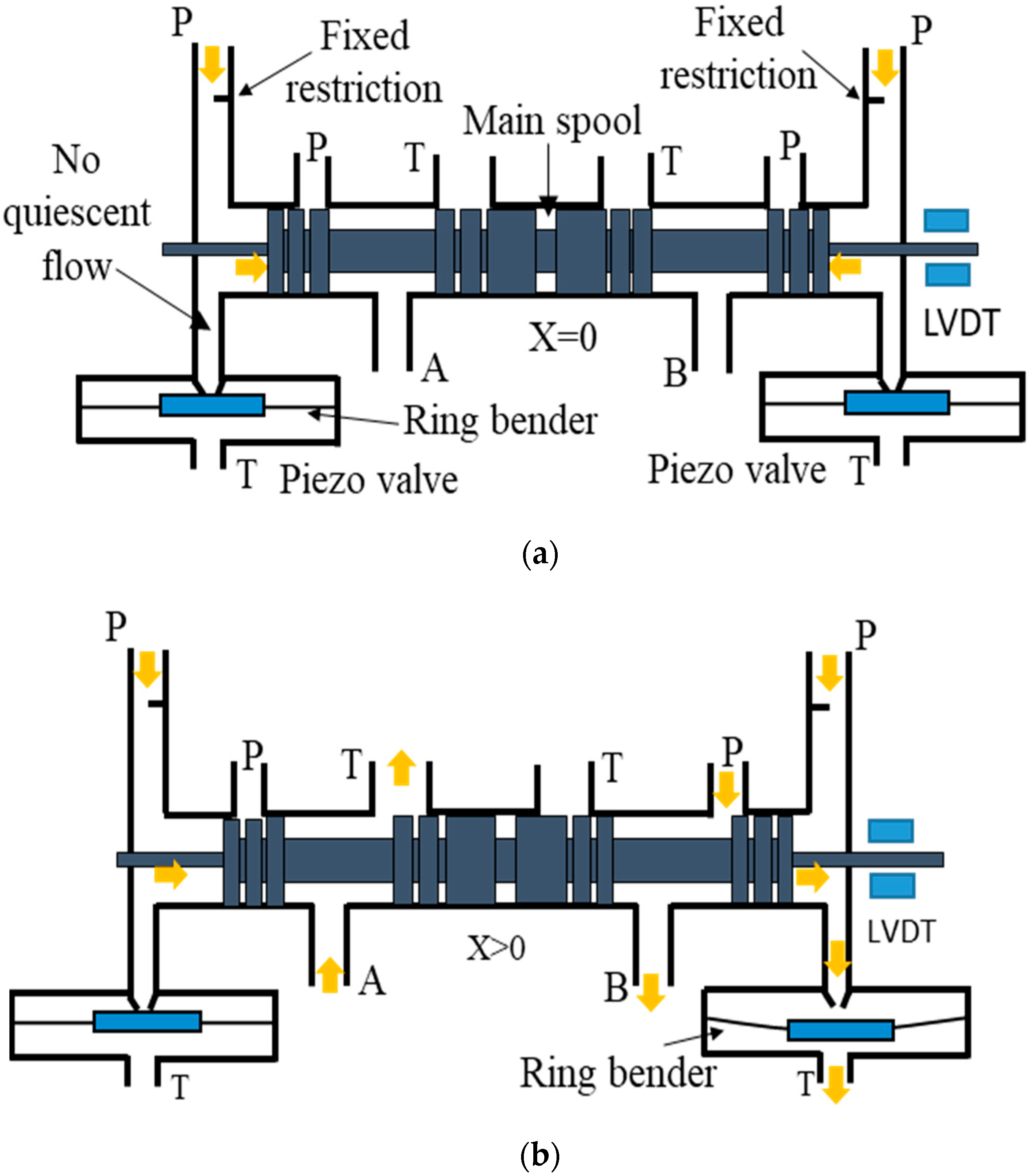
2.1. Novel Servovalve Concept
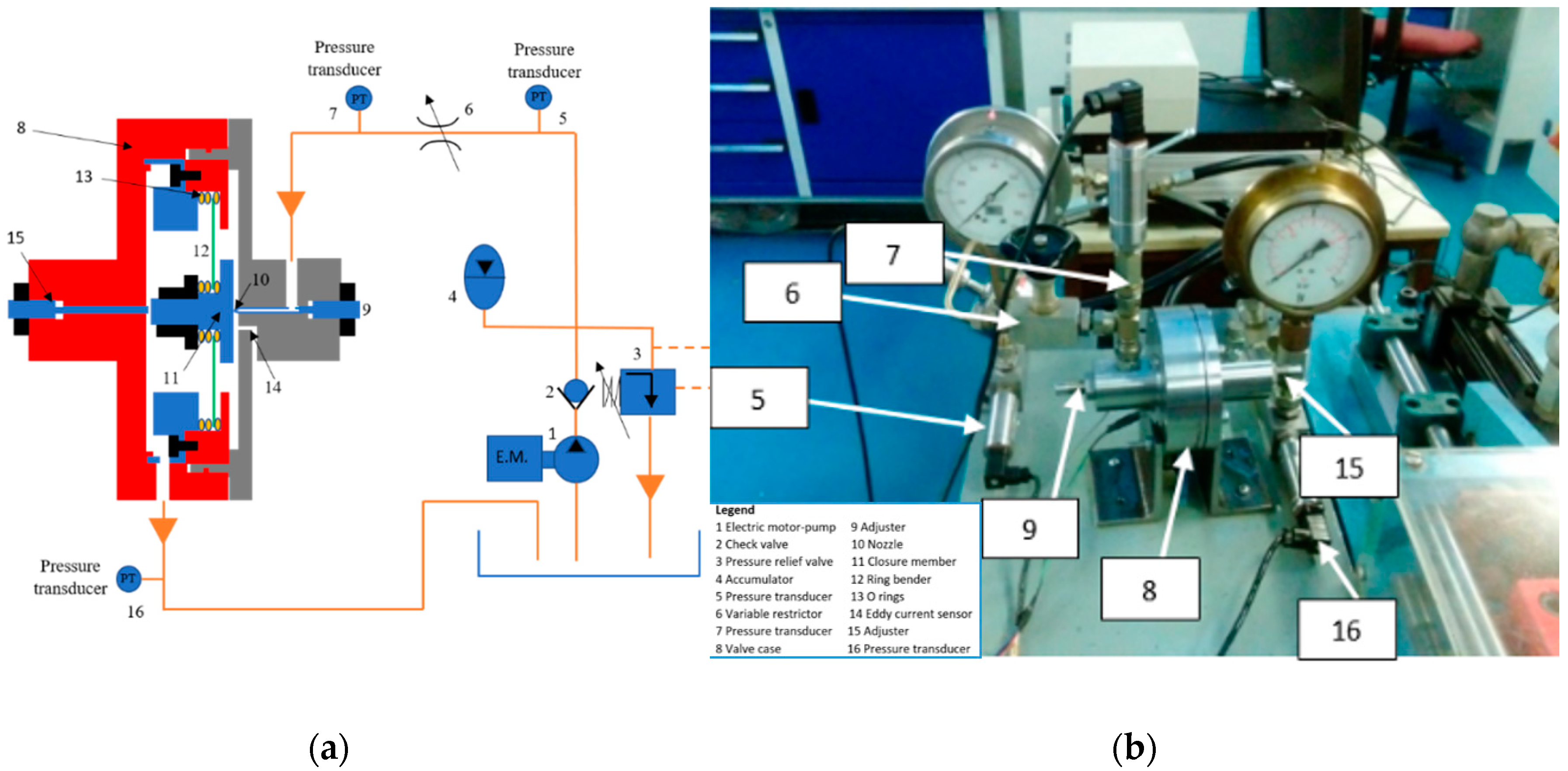
2.2. Valve Prototype and Hydraulic Test Rig
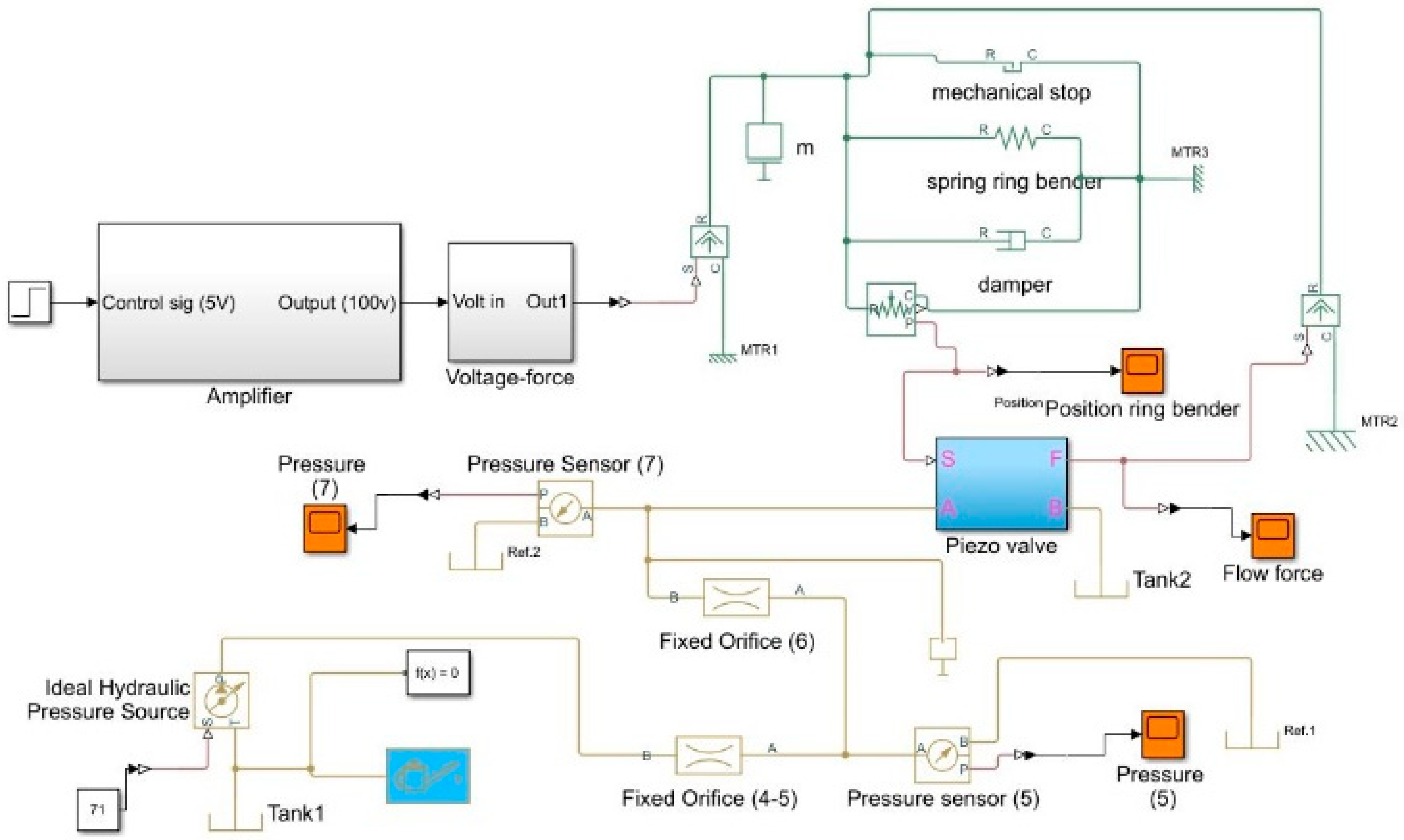
2.3. Numerical Model of the Piezo-Valve
3. Results
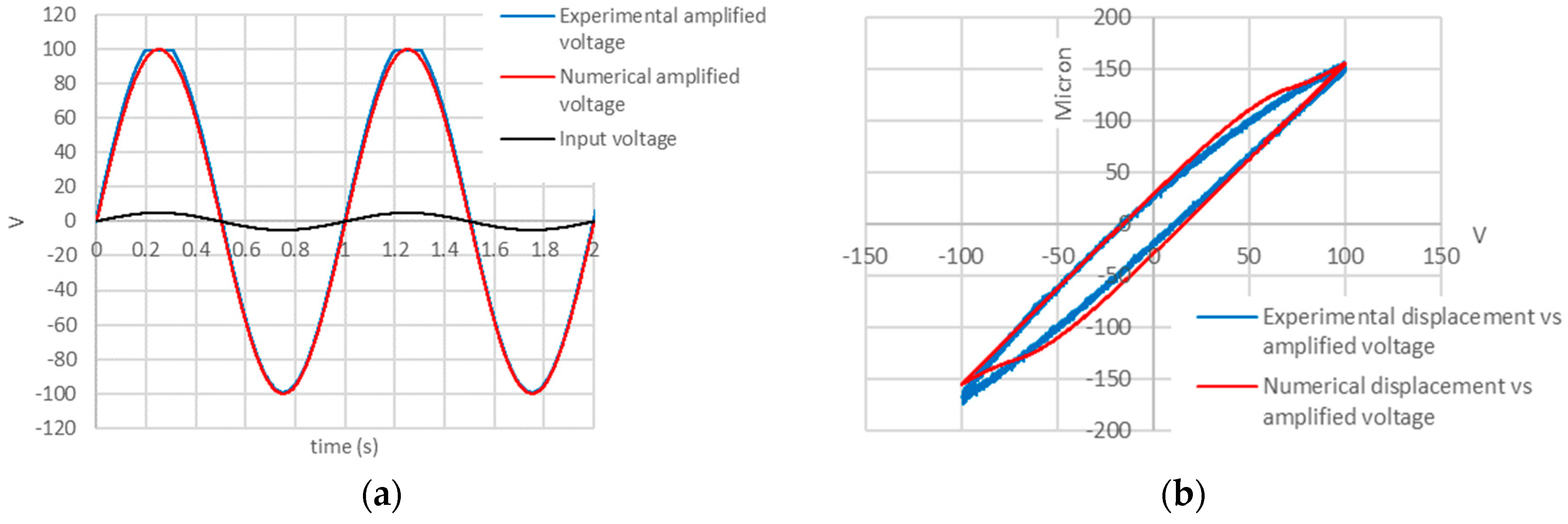
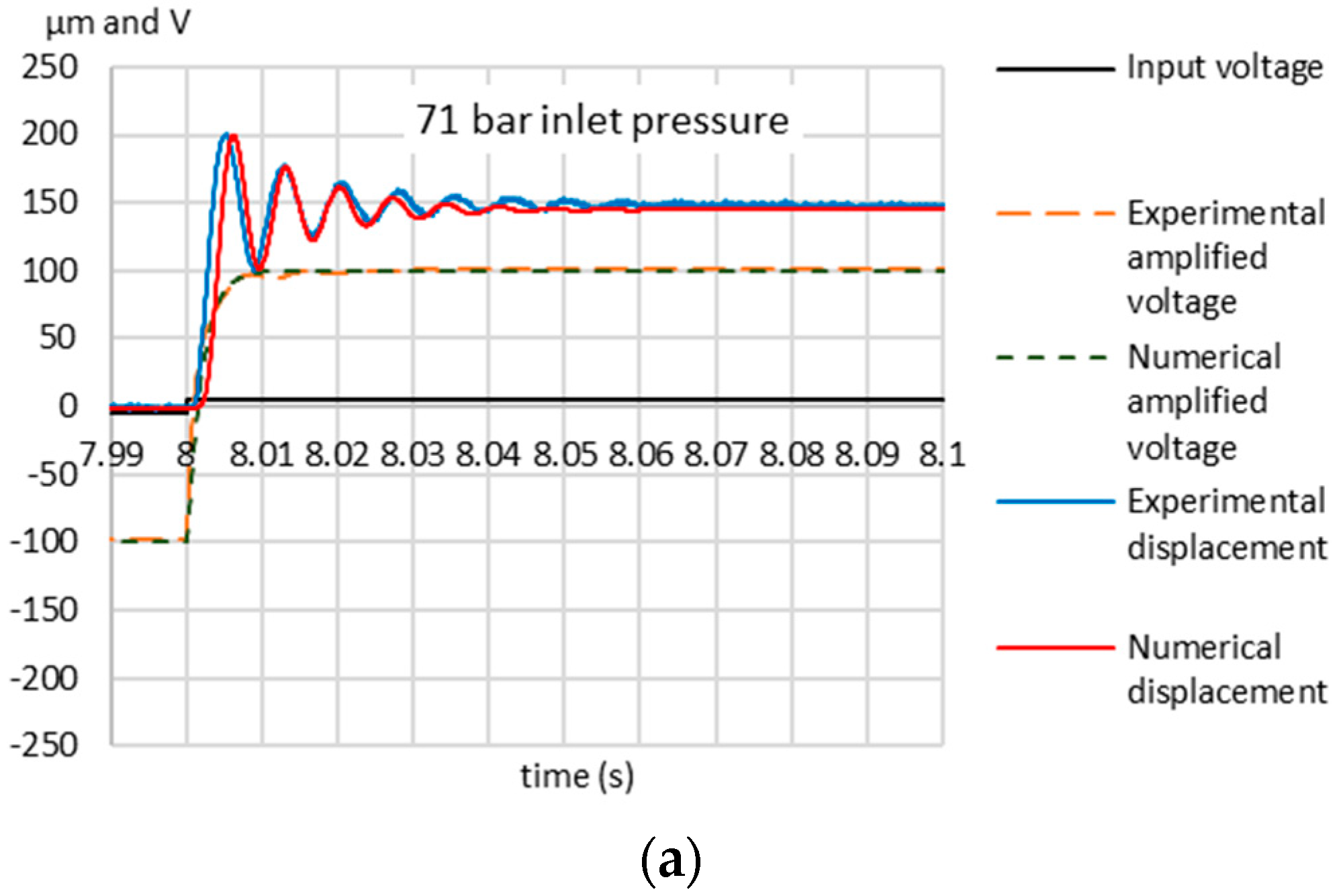
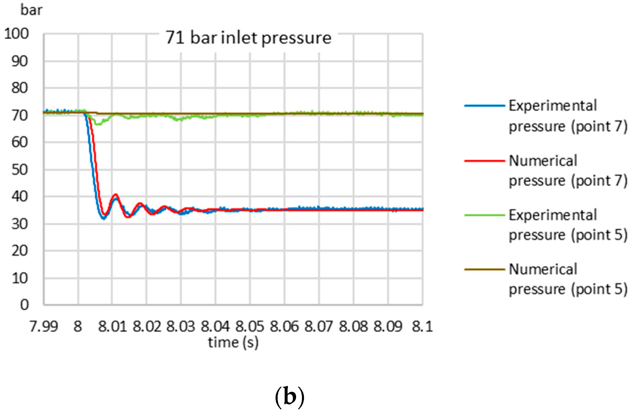
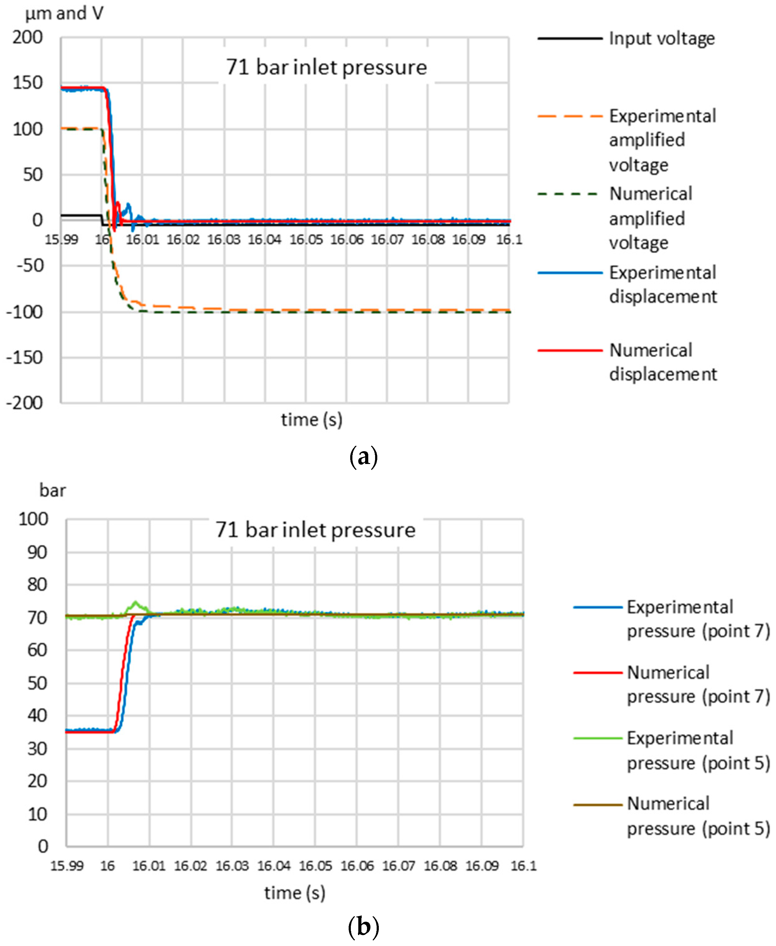
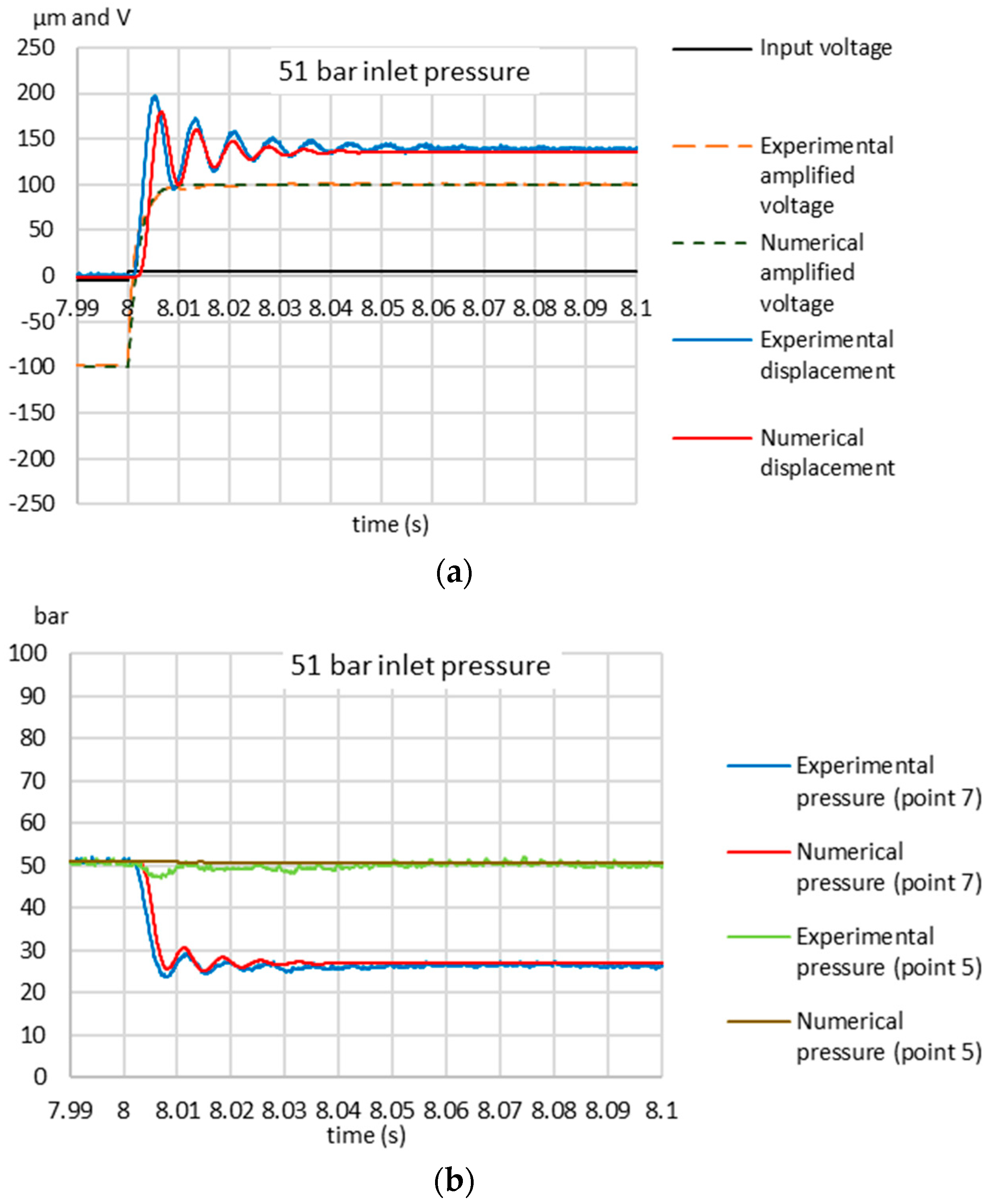
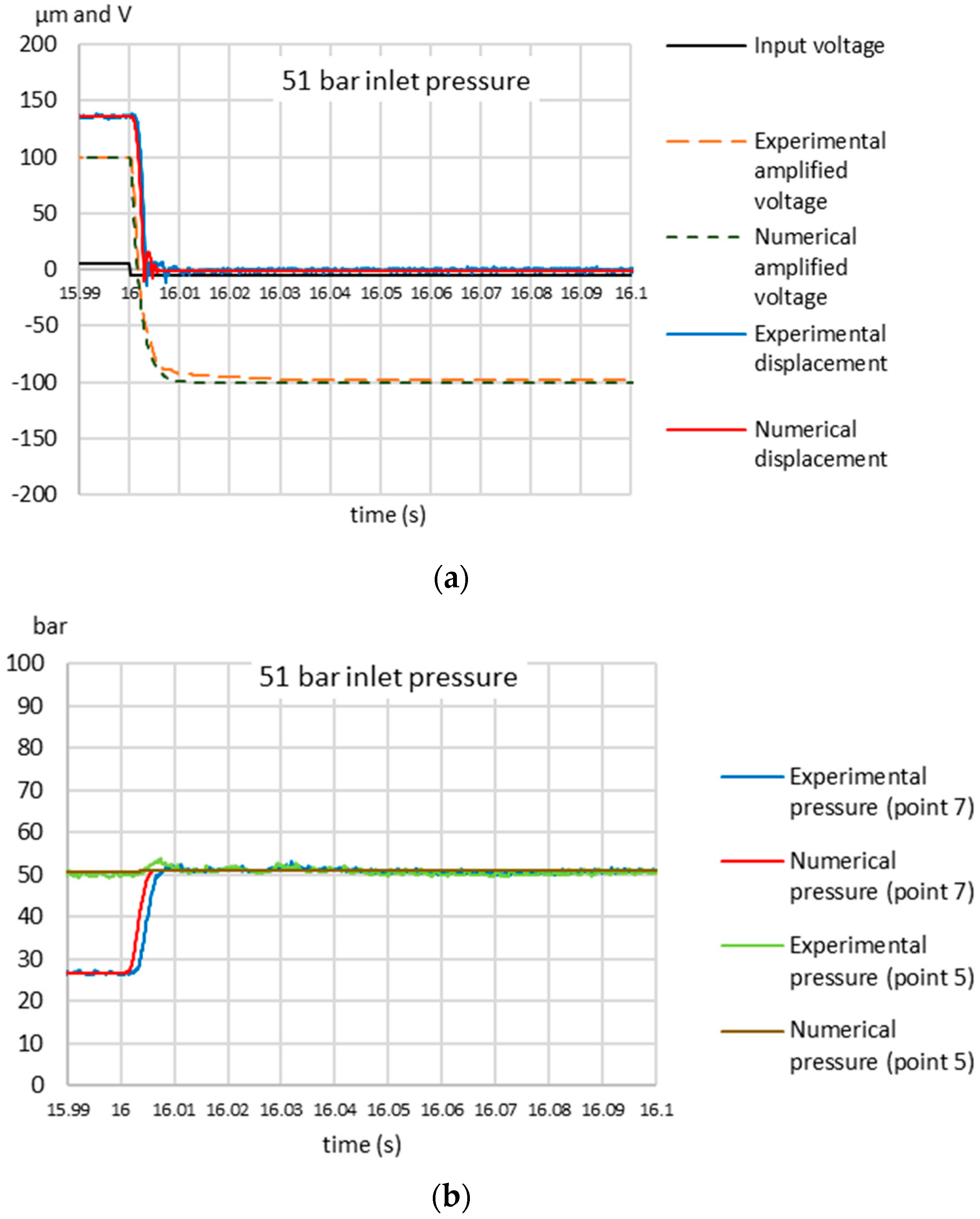
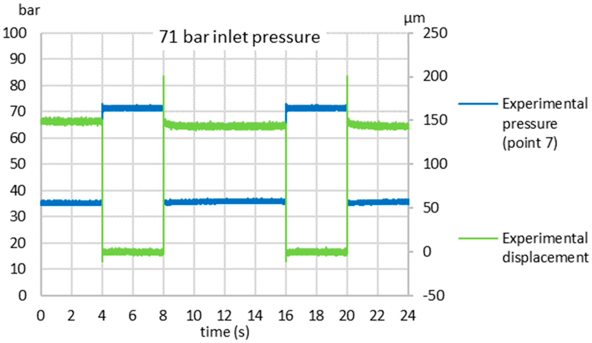
3.1. Experimental Results and Comparison with the Numerical Model
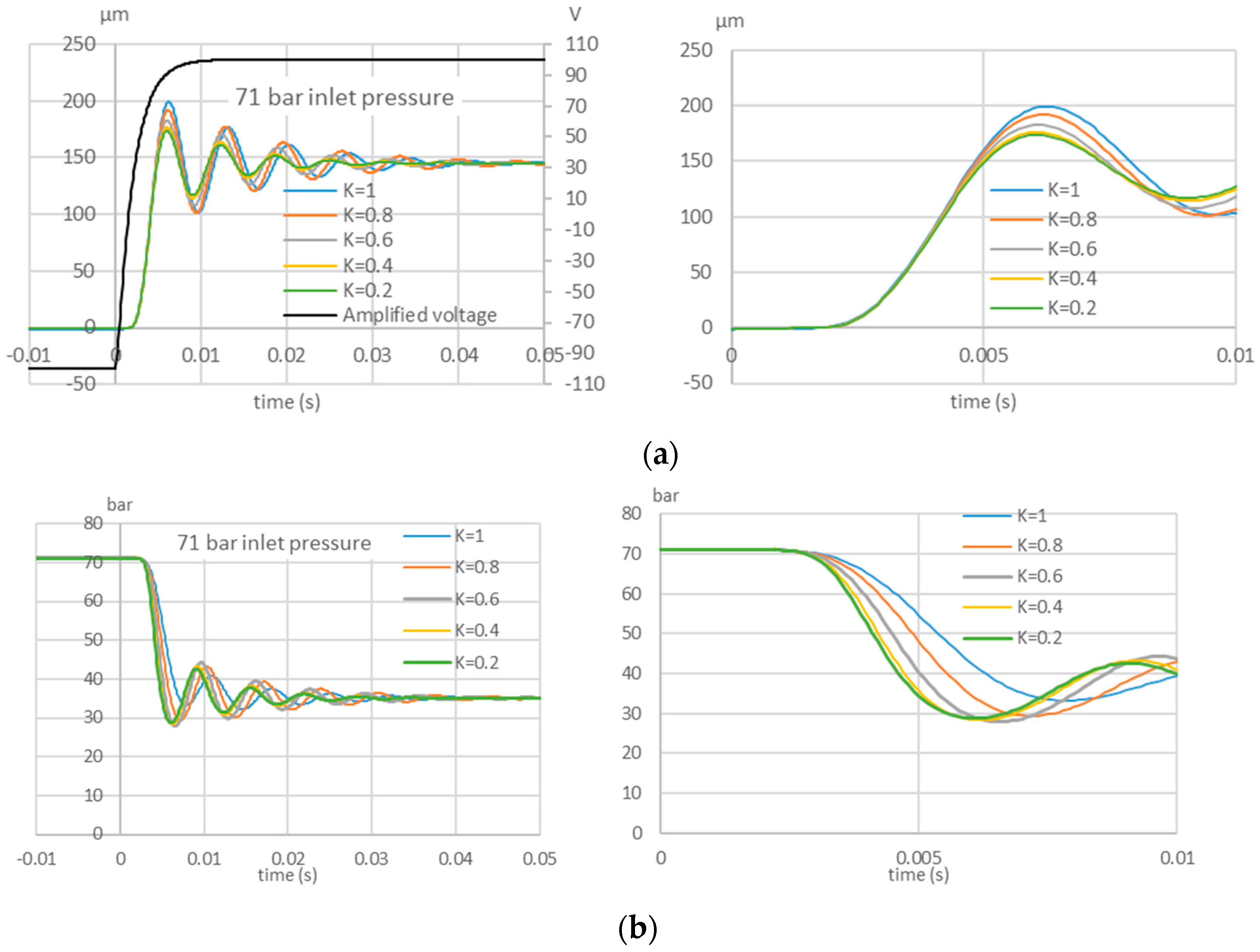
3.2. Numerical Analysis of the Piezo-Valve
4. Conclusions
Author Contributions
Funding
Conflicts of Interest
Nomenclature
| Ar | Restriction area [mm2] |
| C | Capacitance [nF] |
| CD | Discharge coefficient |
| Crb | Damping coefficient of the moving parts [Ns/m] |
| Cstop | Damping coefficient hard stop [Ns/m] |
| D | Diameter of the hydraulic chamber [mm] |
| D0 | Diameter of the hydraulic chamber of the prototype [mm] |
| d | Diameter of the piezo valve orifice [mm] |
| E | Bulk modulus [N/m2] |
| E0 | Pure liquid bulk modulus [N/m2] |
| Fflow | Flow force [N] |
| Frb | Actuation force of the ring bender [N] |
| Imax | Maximum current [A] |
| K | Proportional factor |
| Ka | Gain of the amplifier |
| Kd,v | Ring bender conversion factor [N/V] |
| Krb | Spring stiffness of the ring bender [N/m] |
| Kstop | Stiffness of the hard stop [N/m] |
| L | Length of the hydraulic chamber [mm] |
| L0 | Length of the hydraulic chamber of the prototype [mm] |
| m | Mass of the moving parts [kg] |
| m0 | Mass of the moving parts of the prototype [kg] |
| n | Hysteresis non-linear term [V] |
| p | Absolute pressure [N/m2] |
| p0 | Atmospheric pressure [N/m2] |
| q | Volumetric flow rate [m3/s] |
| Vamp | Voltage from the amplifier [V] |
| Vc | Control voltage [V] |
| x | Ring bender displacement [mm] |
| xmax | Maximum displacement of the ring bender [mm] |
| xmin | Minimum displacement of the ring bender [mm] |
| x0 | Pre-compression [mm] |
| α | Parameter for the hysteresis formula |
| β | Parameter for the hysteresis formula |
| γ | Ratio of the specific heats |
| δ | Parameter for the hysteresis formula |
| ε | Relative gas content at atmospheric pressure |
| ξ | Damping factor of the amplifier |
| Fluid density at atmospheric conditions [kg/m3] | |
| ωn | Natural frequency of the amplifier [rad/s] |
| ωn,0 | Natural frequency of the experimental amplifier [rad/s] |
References
- Plummer, A.R. Electrohydraulic servovalves—Past, present, and future. In Proceedings of the 10th International Fluid Power Conference, IFK2016, Dresden, Germany, 8 March 2016; pp. 405–424. [Google Scholar]
- Tamburrano, P.; Plummer, A.R.; Distaso, E.; Amirante, R. A review of electro-hydraulic servovalve research and development. Int. J. Fluid Power 2019, 20, 53–98. [Google Scholar] [CrossRef]
- Chattopadhyay, H.; Kundu, A.; Saha, B.K.; Gangopadhyay, T. Analysis of flow structure inside a spool type pressure regulating valve. Energy Convers Manag. 2012, 53, 196–204. [Google Scholar] [CrossRef]
- Saha, B.K.; Chattopadhyay, H.; Mandal, P.B.; Gangopadhyay, T. Dynamic simulation of a pressure regulating and shut-off valve. Comput Fluids 2014, 101, 233–240. [Google Scholar] [CrossRef]
- Simic, M.; Herakovic, N. Reduction of the flow forces in a small hydraulic seat valve as alternative approach to improve the valve characteristics. Energy Convers Manag. 2015, 89, 708–718. [Google Scholar] [CrossRef]
- Herakovic, N.; Duhovnik, J.; Simic, M. CFD simulation of flow force reduction in hydraulic valves. Teh. Vjesn. Tech. Gaz. 2015, 22, 555–564. [Google Scholar] [CrossRef]
- Tamburrano, P.; Plummer, A.R.; Distaso, E.; Amirante, R. A review of direct drive proportional electrohydraulic spool valves: Industrial state-of-the-art and research advancements. J. Dyn. Syst. Meas. Control 2019, 141, 020801. [Google Scholar] [CrossRef]
- Amirante, R.; Distaso, E.; Tamburrano, P. Sliding spool design for reducing the actuation forces in direct operated proportional directional valves: Experimental validation. Energy Convers. Manag. 2016, 119, 399–410. [Google Scholar] [CrossRef]
- Amirante, R.; Distaso, E.; Tamburrano, P. Experimental and numerical analysis of cavitation in hydraulic proportional directional valves. Energy Convers. Manag. 2014, 87, 208–219. [Google Scholar] [CrossRef]
- Amirante, R.; Catalano, L.A.; Poloni, C.; Tamburrano, P. Fluid-dynamic design optimization of hydraulic proportional directional valves. Eng. Optim. 2014, 46, 1295–1314. [Google Scholar] [CrossRef]
- Bang, Y.B.; Joo, C.S.; Lee, K.I.; Hur, J.W.; Lim, W.K. Development of a two-stage high speed electrohydraulic servovalve systems using stacktype piezoelectric elements. In Proceedings of the IEEE/ASME international conference on advanced intelligent mechatronics (AIM 2003), Kobe, Japan, 20–24 July 2003; Volume 1, pp. 131–136. [Google Scholar] [CrossRef]
- Branson, D.T.; Wang, F.C.; Johnston, D.N.; Tilley, D.G.; Bowen, C.R.; Keogh, P.S. Piezoelectrically actuated hydraulic valve design for high bandwidth and flow performance. Proc. Inst. Mech. Eng. Part I J. Syst. Control Eng. 2011, 225, 345–359. [Google Scholar] [CrossRef]
- Reichert, M. High response hydraulic servovalve with piezo-actuators in the pilot stage. Olhydraulik Pneum. 2006, 12, 1–17. [Google Scholar]
- Lindler, J.E.; Anderson, E.H. Piezoelectric direct drive servovalve. In Proceedings of the SPIE’s 9th Annual International Symposium on Smart Structures and Materials, San Diego, CA, USA, 17–21 March 2002. [Google Scholar] [CrossRef]
- Jeon, J.; Han, C.; Han, Y.M.; Choi, S.B. A new type of a direct-drive valve system driven by a piezostack actuator and sliding spool. Smart Mater. Struct. 2014, 23, 075002. [Google Scholar] [CrossRef]
- Karunanidhi, S.; Singaperumal, M. Mathematical modelling and experimental characterization of a high dynamic servo valve integrated with piezoelectric actuator. Proc. Inst. Mech. Eng. Part I J. Syst. Control Eng. 2010, 224, 419–435. [Google Scholar] [CrossRef]
- Milecki, A. Modelling and investigation of electrohydraulic servovalve with piezo element. Proc. Inst. Mech. Technol. 2006, 26, 181–188. [Google Scholar]
- Lihui, Z.; Shiju, E.; Xilin, Z.; Chunfu, G. Development of hydroelectric servovalve based on piezoelectric elements. In Proceedings of the 2010 International Conference on Mechanic Automation and Control Engineering MACE2010, Wuhan, China, 26–28 June 2010; pp. 3330–3333. [Google Scholar]
- Guang-Ming, C.; Peng, L.I.; Zhi-Gang, Y.; Shi-ju, E.; Jian-fang, L.I. Double-nozzle piezoelectric servovalve. Guangxue Jingmi Gongcheng/Opt. Precis. Eng. 2005, 13, 276–282. [Google Scholar]
- Bertin, M.J.F.; Plummer, A.R.; Bowen, C.R.; Johnston, D.N. An Investigation of Piezoelectric Ring Benders and Their Potential for Actuating Servo Valves. In Proceedings of the ASME/BATH 2014 Symposium on Fluid Power and Motion Control. ASME/BATH 2014 Symposium on Fluid Power and Motion Control, Bath, UK, 10–12 September 2014; V001T01A034. ASME: New York, NY, USA. [Google Scholar] [CrossRef]
- Tamburrano, P.; Amirante, R.; Distaso, E.; Plummer, A.R. Full simulation of a piezoelectric double nozzle flapper pilot valve coupled with a main stage spool valve. Energy Procedia 2018, 148, 487–494. [Google Scholar] [CrossRef]
- Grunwald, A.; Olabi, A.G. Design of a magnetostrictive (MS) actuator. Sens. Actuators A Phys. 2008, 144, 161–175. [Google Scholar] [CrossRef]
- Zhu, Y.; Li, Y. Development of a deflector-jet electrohydraulic servovalve using a giant magnetostrictive material. Smart Mater. Struct. 2014, 23. [Google Scholar] [CrossRef]
- Zhu, Y.; Yang, X.; Wang, X. Development of a four nozzle flapper servovalve driven by a giant magnetostrictive actuator. Proc. Inst. Mech. Eng. Part I J. Syst. Control Eng. 2015, 229, 293–307. [Google Scholar] [CrossRef]
- Karunanidhi, S.; Singaperumal, M. Design, analysis and simulation of magnetostrictive actuator and its application to high dynamic servo valve. Sens. Actuators A Phys. 2010, 157, 185–197. [Google Scholar] [CrossRef]
- Yang, Z.; He, Z.; Li, D.; Xue, G.; Cui, X. Hydraulic amplifier design and its application to direct drive valve based on magnetostrictive actuator. Sens. Actuators A Phys. 2014, 216, 52–63. [Google Scholar] [CrossRef]
- Persson, L.J.; Plummer, A.R.; Bowen, C.R.; Brooks, I. Design and Modelling of a Novel Servovalve Actuated by a Piezoelectric Ring Bender. In Proceedings of the ASME/BATH 2015 Symposium on Fluid Power and Motion Control, ASME/BATH 2015 Symposium on Fluid Power and Motion Control, Chicago, IL, USA, 12–14 October 2015; V001T01A043. ASME: New York, NY, USA. [Google Scholar] [CrossRef]
- Tamburrano, P.; Amirante, R.; Distaso, E.; Plummer, A.R. A Novel Piezoelectric Double-Flapper Servovalve Pilot Stage: Operating Principle and Performance Prediction. In Proceedings of the Bath/ASME Symposium on Fluid Power and Motion Control FPMC 2018, Bath, UK, 12–14 September 2018; University of Bath: Bath, UK, 2018. [Google Scholar]
- Noliac. Available online: http://www.noliac.com/products/actuators/platestacks/ (accessed on 1 September 2017).
- Matlab & Simulink. SimscapeTM User’s Guide R2019b; The Mathworks, Inc., 1 Apple Hill Drive: Natick, MA, USA, 2019. [Google Scholar]
- Merritt, H. Hydraulic Control System; John Wiley and Sons: New York, NY, USA; London, UK; Sydney, Australia, 1967. [Google Scholar]
- Moog. Available online: http://www.moog.com/products/servovalves-servo-proportional-valves.html (accessed on 1 September 2017).
- Bhatti, J.; Plummer, A.R. Hydraulic running robots: The prospects for fluid power in agile locomotion. In Proceedings of the 12th Scandinavian Conference on Fluid Power (SICFP’11), Tampere, Finland, 18–20 May 2011. [Google Scholar]


| Parameter | Value |
|---|---|
| Outer diameter of the ring bender | 40 mm |
| Inner diameter of the ring bender | 8 mm |
| Height of the ring bender | 0.7 mm |
| Maximum theoretical displacement of the ring bender | ±185 µm |
| Maximum theoretical force of the ring bender | ±13 N |
| Operating voltage of the ring bender | ±100 V |
| Diameter of the nozzle (10) | 1 mm |
| Equivalent length of the oil chamber between the restriction (6) and the nozzle (10) | 60 mm |
| Equivalent diameter of the oil chamber between the restriction (6) and the nozzle (10) | 20 mm |
| Area of the restriction (6) | Variable |
| Mass of the moving parts of the piezo-valve (closure member, ring-bender, o-rings) | 90 g |
| Component | Parameter | Symbol | Value |
|---|---|---|---|
| Oil | Density | 851 kg/m3 | |
| Relative gas content | ε | 0.01 | |
| Supply line (from accumulator 4 to point 5) | Supply pressure | p4 | 71 bar/51 bar |
| Fictitious restriction area | 4 mm2 | ||
| Discharge coefficient | CD,4-5 | 0.7 | |
| Variable restrictor (6) | Restriction area | Ar,6 | 0.42 mm2 |
| Discharge coefficient | CD,6 | 0.7 | |
| Oil chamber volume (from restriction 6 to nozzle 10) | Equivalent diameter | Do | 20 mm |
| Equivalent length | Lo | 60 mm | |
| Piezo valve | Ring bender conversion factor (force over voltage) | Kd,v | 0.13 N/V |
| Diameter of the nozzle (10) | d | 1 mm | |
| Discharge coefficient | CD,v | 0.65 | |
| Mass of the moving parts | m0 | 90 g | |
| Damping coefficient | Crb | 26 Ns/m | |
| Ring bender stiffness | krb | 70,000 N/m | |
| Pre-compression of the ring bender | x0 | 50 μm | |
| Stop damping coefficient | 500 Ns/m | ||
| Stop stiffness | 107 N/m | ||
| Maximum displacement of the ring bender | None | ||
| Minimum displacement of the ring bender | 0 | ||
| Discharge line | Pressure | pT | 1 bar |
| Amplifier | Natural frequency | ωn,0 | 1400 rad/s |
| Damping factor | ξ | 1.5 | |
| Maximum current | Imax | 1A | |
| Capacitance | 2 × 1740 nF | ||
| Gain of the amplifier | 20 |
© 2020 by the authors. Licensee MDPI, Basel, Switzerland. This article is an open access article distributed under the terms and conditions of the Creative Commons Attribution (CC BY) license (http://creativecommons.org/licenses/by/4.0/).
Share and Cite
Tamburrano, P.; Plummer, A.R.; De Palma, P.; Distaso, E.; Amirante, R. A Novel Servovalve Pilot Stage Actuated by a Piezo-electric Ring Bender: A Numerical and Experimental Analysis. Energies 2020, 13, 671. https://doi.org/10.3390/en13030671
Tamburrano P, Plummer AR, De Palma P, Distaso E, Amirante R. A Novel Servovalve Pilot Stage Actuated by a Piezo-electric Ring Bender: A Numerical and Experimental Analysis. Energies. 2020; 13(3):671. https://doi.org/10.3390/en13030671
Chicago/Turabian StyleTamburrano, Paolo, Andrew R. Plummer, Pietro De Palma, Elia Distaso, and Riccardo Amirante. 2020. "A Novel Servovalve Pilot Stage Actuated by a Piezo-electric Ring Bender: A Numerical and Experimental Analysis" Energies 13, no. 3: 671. https://doi.org/10.3390/en13030671
APA StyleTamburrano, P., Plummer, A. R., De Palma, P., Distaso, E., & Amirante, R. (2020). A Novel Servovalve Pilot Stage Actuated by a Piezo-electric Ring Bender: A Numerical and Experimental Analysis. Energies, 13(3), 671. https://doi.org/10.3390/en13030671