Article

New Modulation Technique to Mitigate Common Mode Voltage Effects in Star-Connected Five-Phase AC Drives

1
Derpartment of Electronic Technology, University of the Basque Country (UPV/EHU), Plaza Ingeniero Torres Quevedo 1, 48013 Bilbao, Spain
2
Tecnalia Research and Innovation, C. Mikeletegi 7, 20009 Donostia, Spain
*
Author to whom correspondence should be addressed.
Energies 2020, 13(3), 607; https://doi.org/10.3390/en13030607
Submission received: 29 November 2019 / Revised: 27 January 2020 / Accepted: 29 January 2020 / Published: 31 January 2020
(This article belongs to the Special Issue Advances in Rotating Electric Machines)

Abstract

:
Star-connected multiphase AC drives are being considered for electromovility applications such as electromechanical actuators (EMA), where high power density and fault tolerance is demanded. As for three-phase systems, common-mode voltage (CMV) is an issue for multiphase drives. CMV leads to shaft voltages between rotor and stator windings, generating bearing currents which accelerate bearing degradation and produce high electromagnetic interferences (EMI). CMV effects can be mitigated by using appropriate modulation techniques. Thus, this work proposes a new Hybrid PWM algorithm that effectively reduces CMV in five-phase AC electric drives, improving their reliability. All the mathematical background required to understand the proposal, i.e., vector transformations, vector sequences and calculation of analytical expressions for duty cycle determination are detailed. Additionally, practical details that simplify the implementation of the proposal in an FPGA are also included. This technique, HAZSL5M5-PWM, extends the linear range of the AZSL5M5-PWM modulation, providing a full linear range. Simulation results obtained in an accurate multiphase EMA model are provided, showing the validity of the proposed modulation approach.

1. Introduction

AC electric drives are used in a wide variety of industrial applications such as in compressors [1], in electric vehicle propulsion systems [2,3] and in more electric aircraft (MEA) [4], among others. Although three-phase systems dominate the AC drive market, multiphase solutions are gaining popularity [5,6,7]. Multiphase systems are preferable for applications where high fault tolerance is required [8], such as for MEA applications, where electromechanical actuators (EMA) for control surfaces, fuel pumps, landing gears, environmental control systems and starter-generators need to be operated [9,10,11]. Apart from their intrinsic fault tolerance, other benefits of multiphase drives include a reduced current per phase (reducing copper losses and increasing efficiency) [4], noise and electromagnetic interference (EMI) minimization [12,13], higher power density and lower torque ripple [14], making them attractive for transport electrification. Among the multiphase topologies available in the scientific literature, star-connected five-phase technologies (Figure 1) can be highlighted, as they provide a good trade-off between system complexity and fault tolerance [15,16]. Specifically, multiphase permanent magnet synchronous machines (PMSM) are being considered for aircrafts due to their superior power density [17,18].
In general, AC electric drives can experience issues due to the common-mode voltage (CMV) [19] and common mode currents (CMC) [20]. CMV variations are generated by the commutation of the power converter devices, producing EMI [21] and bearing currents that can compromise the integrity of the electric machine [22]. Such voltage variations create new capacitive paths through the motor bearings, leading to premature aging. Capacitive currents, electrostatic discharge machine (EDM) currents, circulating currents and rotor-to-ground currents can flow through the bearings [23,24] (Figure 2), and their harmful effects depend on the type of bearing, size of the machine and how the machine is used.
Operating at higher switching frequencies can entail more severe CMV related issues (additional EMI generation and larger number of dv/dt) [26]. As considerable efforts are being carried out to widespread the usage of wide bandgap (WBG) devices in AC drives, much higher switching frequencies are expected in the future, making the investigation on CMV mitigation a popular topic [13,19,20]. Thus, a wide variety of solutions have been proposed in the literature. Such solutions can be classified as passive or active. Passive solutions are those which mitigate or eliminate the harmful effects generated by CMV, while active solutions are intended to reduce or totally avoid CMV generation. Among passive solutions, Faraday shielding [27,28], ceramic and hybrid bearings [22,29], shielded cables [23,30] and shaft grounding rings [27,31] can be highlighted. On the other hand, modulation techniques and new inverter topologies such as multilevel inverters [32], single-phase transformerless inverters [33,34] and three-phase inverters [35] among others [36] are the most common active solutions. Among all these solutions, modulation algorithms can be considered for CMV reduction in star-connected five-phase AC drives due to their ease of implementation, low cost, and because no additional hardware is needed.
In [37], the authors initially proposed a CMV reduction modulation technique for five-phase inverters, named AZSL5M5-PWM. However, the proposal has been only considered for passive loads (star-connected R L loads) and solely validated in open-loop. From the obtained results, it has been concluded that the linear range of the original AZSL5M5-PWM is limited, which can prevent the utilization of this technique in electric drives where operation close to the base speed (without entering in field weakening region) is desirable, as is the case in most EMA systems. Thus, a hybrid AZSL5M5-PWM technique (HAZSL5M5-PWM) that provides the same linear range as conventional space vector PWM (SV-PWM) is proposed in this work, and its performance is evaluated in an EMA system.
This manuscript is organized as follows. First of all, conventional SV-PWM for star-connected five-phase power systems is presented, where the harmonic projection of the stator voltages into their corresponding orthogonal subspaces by means of Clarke transformation is mathematically justified. After that and considering the third harmonic elimination constraint, it is shown how CMV variations are generated in the multiphase drive. Secondly, the most relevant reduced common-mode voltage PWM (RCMV-PWM) modulation techniques are briefly described, focusing on their limitations. After that, the proposed Hybrid AZSL5M5-PWM modulation technique is presented providing the required tools for duty cycle calculation, and validated by means of simulation. The target of the proposed modulation technique is to effectively reduce CMV in star connected multiphase systems, while the hybridization is performed to cover the whole operation range of the drive. Open-loop and detailed five-phase EMA simulations are conducted to perform the validation, where not only CMV reduction is verified, but other figures such as total harmonic distortion (THD) and efficiency are evaluated in order to demonstrate that the achieved CMV reduction does not significantly penalize other relevant drive figures.

2. Influence of the SV-PWM Technique in the CMV of a Star-Connected Five-Phase AC Drive

SV-PWM is one of the most used modulation techniques in three-phase and multiphase power systems thanks to its easy digital implementation and optimum DC bus voltage utilization. As a star-connected five-phase system has four degrees of freedom, stator voltages and currents can be represented into two separated two-dimensional planes, α - β and x-y, and one homopolar component by means of the following amplitude invariant Clarke transformation [38]:
v α v β v x v y v 0 = 2 5 1 c o s ( 2 π / 5 ) c o s ( 4 π / 5 ) c o s ( 6 π / 5 ) c o s ( 8 π / 5 ) 0 s i n ( 2 π / 5 ) s i n ( 4 π / 5 ) s i n ( 6 π / 5 ) s i n ( 8 π / 5 ) 1 c o s ( 4 π / 5 ) c o s ( 8 π / 5 ) c o s ( 12 π / 5 ) c o s ( 16 π / 5 ) 0 s i n ( 4 π / 5 ) s i n ( 8 π / 5 ) s i n ( 12 π / 5 ) s i n ( 16 π / 5 ) 1 2 1 2 1 2 1 2 1 2 v a v b v c v d v e .
The Clarke transformation allows us to decouple the 5-dimensional voltage vector in the a b c d e reference frame into three orthogonal subspaces ( α - β , x-y and 0). For a surface-mounted permanent magnet synchronous machine (SM-PMSM), this decoupling is done through the diagonalization of the inductance matrix L (2).
L = L 11 L 12 L 13 L 14 L 15 L 21 L 22 L 23 L 24 L 25 L 31 L 32 L 33 L 34 L 35 L 41 L 42 L 43 L 44 L 45 L 51 L 52 L 53 L 54 L 55 .
For SM-PMSMs, the elements of L can be considered invariant with respect to the rotor angular position, as the surface placed magnets have a permeability near that the one of the air. Therefore, a SM-PMSM behaves like a non-salient pole synchronous machine [39]. As the windings in each phase are manufactured identically, the mutual inductances between any pair of phases separated with the same electrical angle are equal, i.e., L 12 = L 15 = L 21 = L 23 = L 51 = L j k (if j k = 1 ) or L 13 = L 31 = L 25 = L 52 = L j k (if j k = 2 ). Similarly, all the self-inductances are equal ( L 11 = L 22 = = L 55 ). This type of matrix is known as a circulant matrix, and it has some special properties [40]. For example, it guarantees that L is orthogonally diagonalizable by a transformation represented by a 5 × 5 real matrix [41,42].
The circulant matrices are diagonalized by the Fourier Matrix [40,43]. Therefore, the Clarke transformation decomposes the 5-dimensional vectors according to their harmonic components. In the α - β sub-space, the h = 5 ( l 1 ) ± 1 harmonic components are projected while, in the x-y sub-space, the h = 5 ( l 1 ) ± 3 ones are projected, being l { 1 , 3 , 5 , } [41,44]. The harmonic components of order h = 5 l are projected into the zero-sequence or homopolar sub-space. In Table 1, the odd harmonics associated with each sub-space according to the Clarke transformation of (1) are presented for a 5-phase machine.
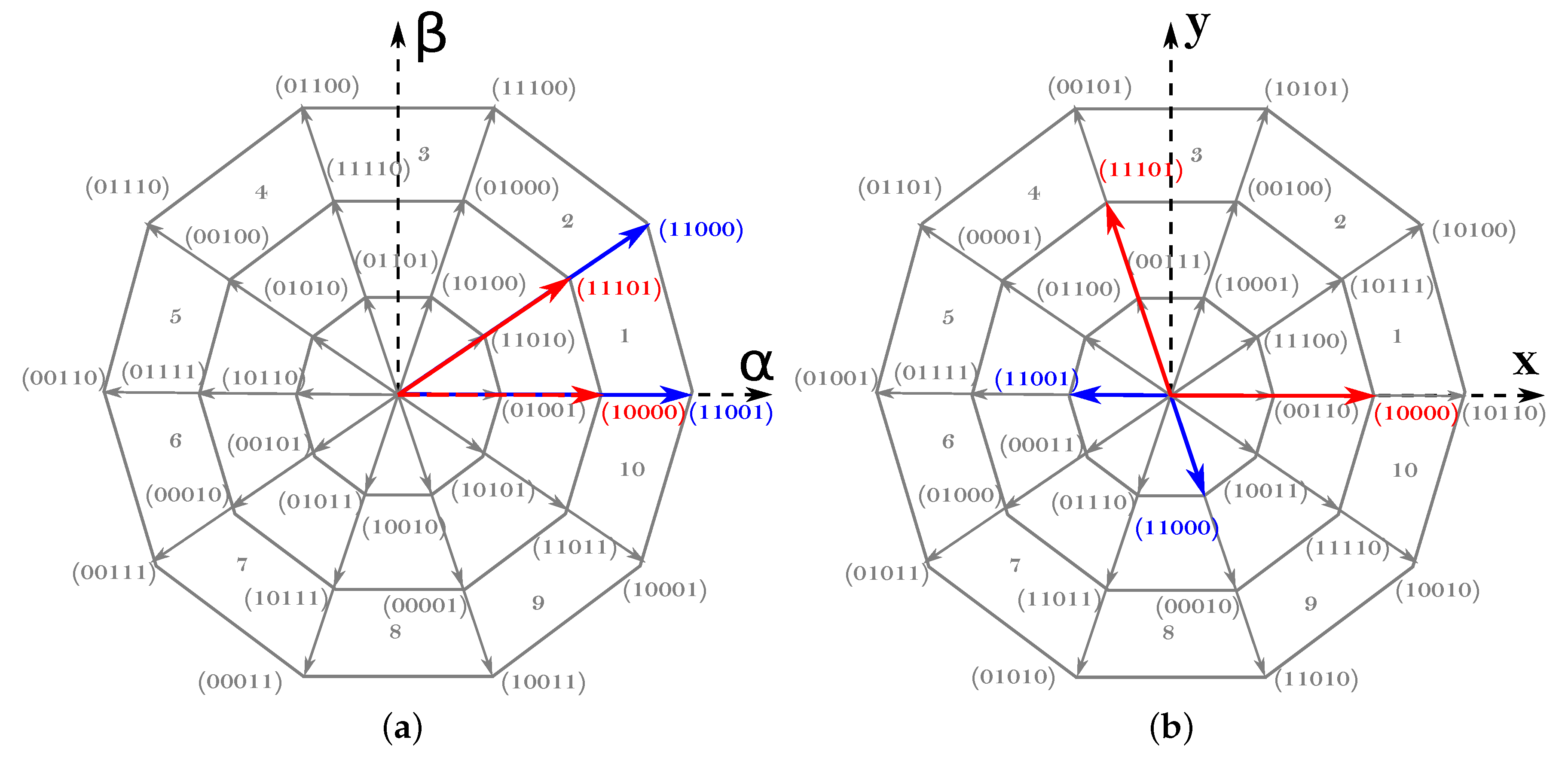
The number of possible switching states or space vectors is 2 5 , where 30 are active vectors and two are zero vectors (Figure 3). Active vectors can be classified depending on their magnitude as:
  • Large vectors, where | V l | = 4 / 5 V D C c o s ( π / 5 ) , which correspond to the outer decagon of Figure 3.
  • Medium vectors, where | V m | = 2 / 5 V D C , which correspond to the middle decagon of Figure 3.
  • Small vectors, where | V s | = 4 / 5 V D C c o s ( 2 π / 5 ) , which correspond to the inner decagon of Figure 3.
For an n-phase system, n 1 active vectors must be applied at each commutation period in order to achieve a sinusoidal output [45]. Thus, four active vectors must be used in a star-connected five-phase system. Although various possible active vector combinations are possible to produce a given output voltage vector, the most common alternative consists on using two large and two medium adjacent vectors. As an illustrative example, Figure 3 shows the vectors used to synthesize a given reference voltage vector located in the first sector of the α - β plane, being the following the application sequence that minimizes switching losses: 00000, 10000, 11000, 11001, 11101, 11111, 11101, 11001, 11000, 10000, 00000. If the third harmonic component needs to be eliminated, the application-time ratio between medium and large vectors must satisfy (3), as with this ratio the sum of the applied vectors in the x-y plane is zero (Figure 3) [46].
t l a r g e t m e d i u m = 1.618 .
As a result, the maximum achievable output voltage following this modulation approach is:
V o m a x = 4 5 cos π 5 cos π 10 = 0.6155 V D C ,
and the CMV generated in the five-phase system is:
V C M ( t ) = 1 5 V a 0 ( t ) + V b 0 ( t ) + V c 0 ( t ) + V d 0 ( t ) + V e 0 ( t ) .
When using SV-PWM and applying the vector sequence that corresponds to the first sector of the α - β plane, the CMV waveform of Figure 4 is obtained. From (5), it can be deduced that all large and short vectors generate CMV levels of ± 0.3 V D C , while CMV levels are of ± 0.1 V D C for medium vectors and of ± 0.5 V D C for null vectors. When evaluating the impact of the CMV, the difference between the maximum and minimum CMV levels ( Δ C M V , Figure 4) must be considered, and the number of CMV variations for each commutation period ( N C M V ) must also be taken into account.

3. RCMV-PWM Techniques

As zero vectors are responsible for generating the maximum CMV levels (Figure 4), most of the RCMV-PWM techniques avoid the application of these vectors to reduce Δ C M V and N C M V . In [38], an extension of the three-phase active zero state PWM (AZS-PWM) [47] modulation technique to the five-phase scenario is proposed. This technique replaces zero vectors by applying two active vectors with the opposite phase at the same time. In this work, this technique will be named AZSL2M2-PWM as, apart from the active vectors that substitute zero vectors, two large (L2) and two medium (M2) vectors are used at each modulation period. This technique shows a good harmonic performance and DC bus utilization, being its linear range 0 m 1 . However, Δ C M V is not greatly reduced, as only ± 0.5 V D C CMV levels are avoided (Table 2). Similarly, a modulation algorithm that employs four large active vectors in conjunction with two active vectors with opposite phases (AZSL4-PWM) is proposed in [38]. This technique has the same linear range as SV-PWM and AZSL2M2-PWM, and considerably reduces Δ C M V , as only applies large vectors. Nonetheless, N C M V remains as for SV-PWM (Table 2).
M5-PWM [48] and L5-PWM [49] techniques completely eliminate Δ C M V and N C M V by only using odd or even medium (M5-PWM), or odd or even large (L5-PWM) active vectors. However, this is achieved at the cost of introducing additional power losses, significantly reducing the linear range up to 0.5257 for M5-PWM (Table 2), and generating high harmonic distortion for L5-PWM, making them inappropriate for many industrial applications. Authors in [48,49] also propose variants that use ten medium (M10-PWM) or ten large (L10-PWM) vectors. These techniques enhance the linear range by increasing the available vectors, but do not reduce Δ C M V and N C M V as much as with M5-PWM and L5-PWM (Table 2).
Among the reviewed techniques, AZSL2M2-PWM and L10-PWM best suit for industrial applications, as they keep the linear range with a reasonable THD while effectively reducing Δ C M V . However, N C M V reduction by means of such modulation algorithms is limited. Thus, a new RCMV-PWM technique that further reduces N C M V while keeping an extended linear range is proposed in the following section.

4. Proposed RCMV-PWM Technique

4.1. Active Zero State L5M5 PWM Technique (AZSL5M5-PWM)

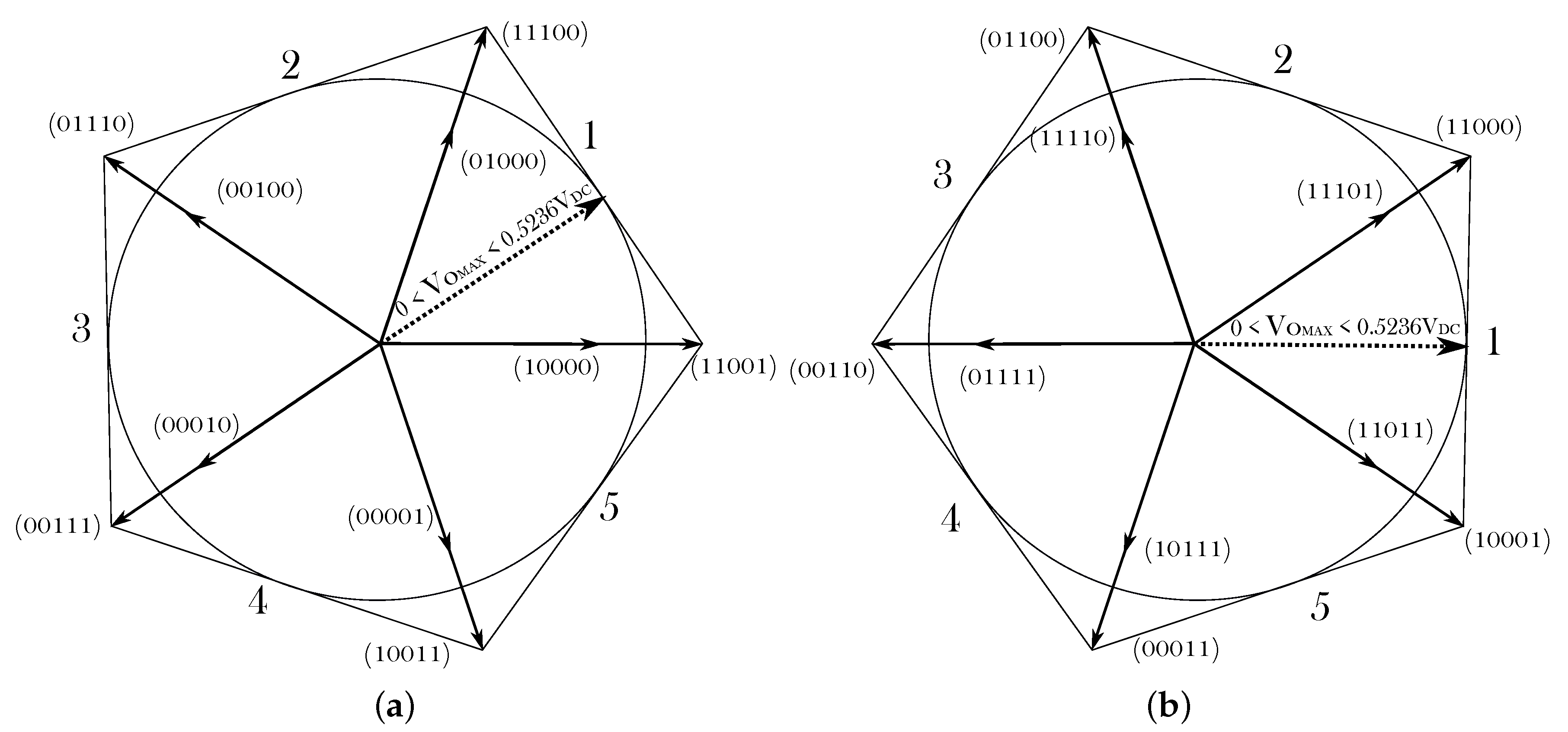
The main part of the proposed RCMV-PWM technique, named active zero state L5M5 PWM (AZSL5M5-PWM), is based on the AZSL2M2-PWM technique [38]. However, and unlike AZSL2M2-PWM, the proposed scheme only uses odd or even vectors to further reduce the CMV voltage variations. For example, if odd vectors are only considered, this leads to the sector distribution of Figure 5a. Thus, five medium vectors and five large vectors are exclusively used to synthesize the reference voltage (Figure 5), and CMV varies between −0.3 V D C and 0.1 V D C (if only even vectors are used, CMV varies between −0.1 V D C and 0.3 V D C ). Consequently, Δ C M V = 0.4 V D C and N C M V = 2 (Table 2).
For the sake of simplicity, all the following analyses are conducted considering the AZSL5M5-PWM variant which exclusively uses odd vectors. The procedure is analogous for even vectors.
The application time of each vector can be easily calculated by solving the following system:
V α * V β * V x * V y * = V m r α V l l α V l r α V m l α V m r β V l l β V l r β V m l β V m r x V l l x V l r x V m l x V m r y V l l y V l r y V m l y δ 1 δ 2 δ 3 δ 4 ,
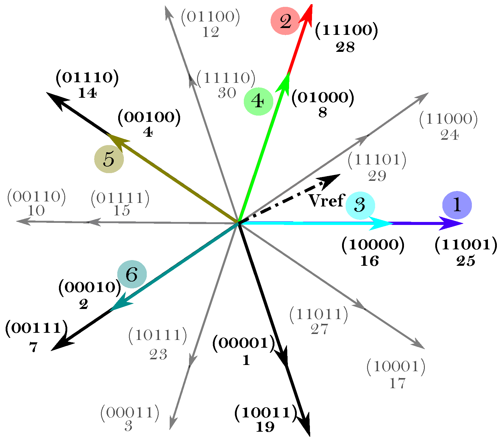
where V α * , V β * , V x * and V y * are the reference voltage projections in the α - β and x-y planes, δ 1 , δ 2 , δ 3 and δ 4 are the duty cycles for each vector, and the 4 × 4 matrix is composed of the magnitudes of the vectors to be applied in each sector, where V m r refers to the modulus of the medium vector on the right side of the reference vector ( V r e f ) (Figure 6, ③), V m l refers to the modulus of the medium vector on the left (Figure 6, ④), and V l l and V l r refer to the modulus of the large vectors on both left and right sides, respectively (Figure 6, ② and ①). Consequently, a 4 × 4 matrix should be defined for each sector. In general, V x * and V y * are set to zero in order to cancel the voltage third harmonic. From (6), it is possible to explicitly determine the values of the duty cycles δ 1 , δ 2 , δ 3 and δ 4 with respect to the reference voltages V α * and V β * :
δ 1 = α 1 V α * / V D C + β 1 V β * / V D C = a 1 s i n 2 s π 5 V α * / V D C + a 1 c o s 2 s π 5 V β * / V D C , δ 2 = α 2 V α * / V D C + β 2 V β * / V D C = a 2 s i n 2 ( s 1 ) π 5 V α * / V D C + a 2 c o s 2 ( s 1 ) π 5 V β * / V D C , δ 3 = α 3 V α * / V D C + β 3 V β * / V D C = a 2 s i n 2 s π 5 V α * / V D C a 2 c o s 2 s π 5 V β * / V D C , δ 4 = α 4 V α * / V D C + β 4 V β * / V D C = a 1 s i n 2 ( s 1 ) π 5 V α * / V D C a 1 c o s 2 ( s 1 ) π 5 V β * / V D C ,
where being s = 1 , 2 5 the corresponding sector in the α β plane, and being a 1 = ( 5 + 5 ) / 2 ( 5 + 5 ) and a 2 = ( 10 / ( 5 + 5 ) .
Regarding the practical implementation of the proposed technique, the 2 × 4 matrix M s can be defined as in (8), where the elements of such matrix can be precalculated for each sector and stored into look-up tables (LUT). In this way, the computational burden and implementation complexity of the algorithm are greatly reduced. Table 3 summarizes the values of M s for each sector s = 1 , 2 5 .
M s = α 1 β 1 α 2 β 2 α 3 β 3 α 4 β 4 .
The main difference of the AZSL5M5-PWM technique over the AZSL2M2-PWM one is that, there are no strictly phase-opposite vector pairs, as only odd/even vectors can be used (Figure 6). To solve this problem, three active vectors (two medium and one large) are used to replace a zero vector. First, the large vector on the right side of the sector (Figure 6, ①) is applied during t 0 / 3 , and each medium vector (Figure 6, ⑤ and ⑥) is applied during t 0 / 3 .
Since the applied vector sequence has a great impact on the CMV and on the switching losses, a sequence with minimum commutations has been chosen for each sector. For instance, when the reference voltage vector lays in sector 1, the next vector sequence is applied: 11001, 11100, 10000, 01000, 00100, 00010, 01000, 10000, 11100 and 11001 (Figure 6). Odd vector variant AZSL5M5-PWM vector sequences depending on the reference voltage sector are given in Table 4. It is important to note that, for AZSL5M5-PWM, more than one commutation is produced at each vector change.
As the α - β plane is divided into five sectors instead of ten (Figure 5), the linear range of AZSL5M5-PWM is slightly reduced, being the maximum achievable output voltage:
V o M A X = 4 5 cos π 5 cos π 5 = 0.5236 V D C .
For applications where achieving full linear range is mandatory, an hybrid modulation that extends AZSL5M5-PWM’s linear range is proposed in the following.

4.2. Hybridization of the Proposed Modulation Algorithm

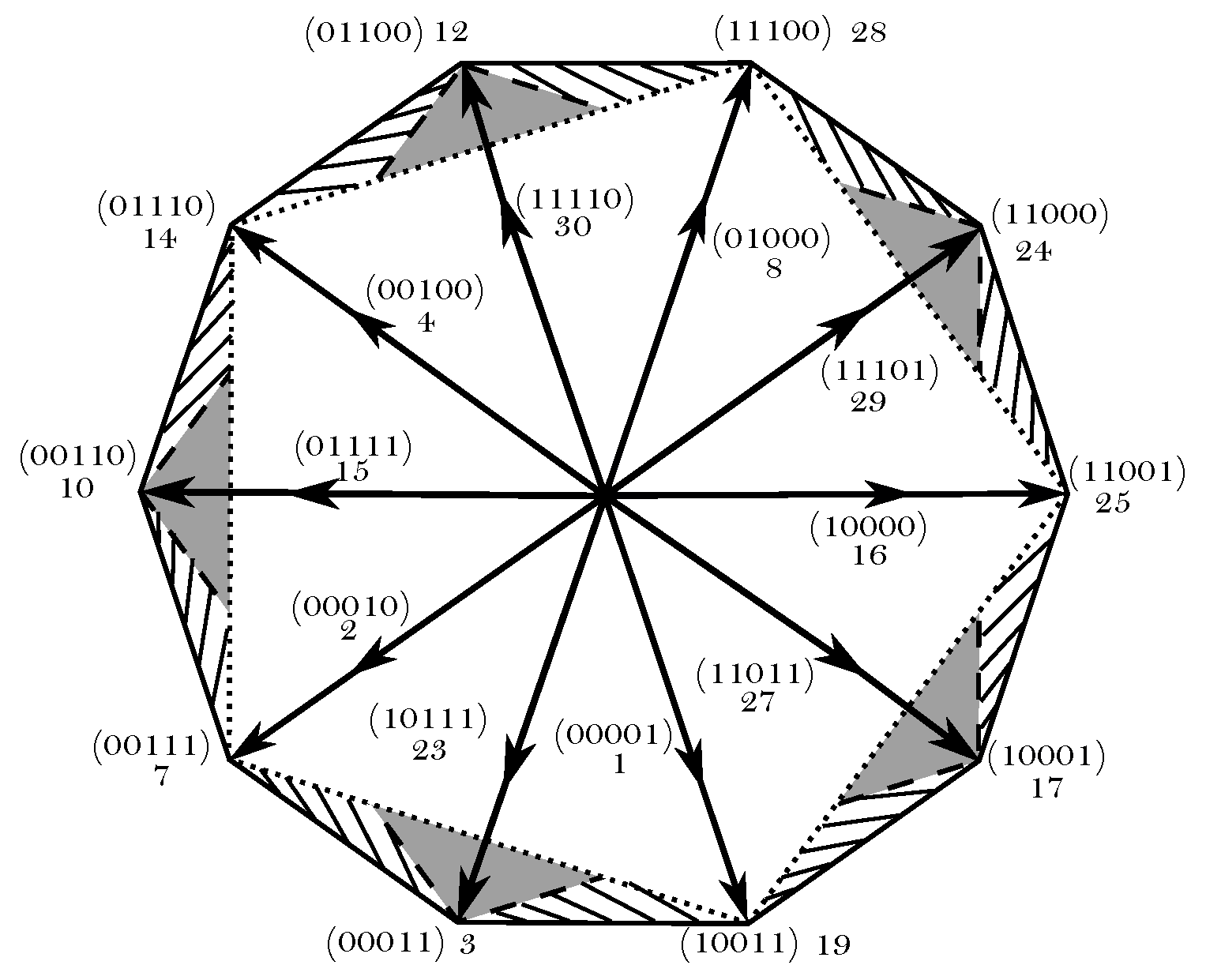
Three operation areas have been differentiated in Figure 7 to carry out the hybrid modulation algorithm and extend the linear range of AZSL5M5-PWM. The AZSL5M5-PWM hybrid variant (HASZL5M5-PWM) that uses odd vectors (white area) has been chosen as the main modulation scheme. When V r e f steps over the boundaries of the white pentagon, two things may occur. On the one hand, V r e f might remain within the shadowed boundaries. In such case, AZSL5M5-PWM with even vectors would be applied. On the other hand, if V r e f is out of the limits of AZSL5M5-PWM with even or odd vectors, SV-PWM can be used to fulfill the remaining area, marked with lines. This modification extends the linear range of AZSL5M5-PWM up to 26.8%. Further variants with greater CMV reduction could also be considered if a full range RCMV-PWM technique, such as AZSL2M2-PWM, is used instead of SV-PWM.

5. Simulation Results

In order to validate the proposal, two simulation platforms have been implemented in Matlab/Simulink. On the one hand, an open-loop model has been created to evaluate the HAZSL5M5-PWM technique and compare its performance with other existing ones regardless of the influence of a control algorithm. On the other, a detailed five-phase EMA model has been implemented to evaluate the proposal in the context of a variable speed AC drive. Without losing generality and in order not to significantly increase the computational burden of the model, ideal switch models that do not consider switching transients nor dead-time effects have been adopted in both simulation platforms. The obtained results and their discussion are provided in the following.

5.1. Open-Loop Model Simulation Results

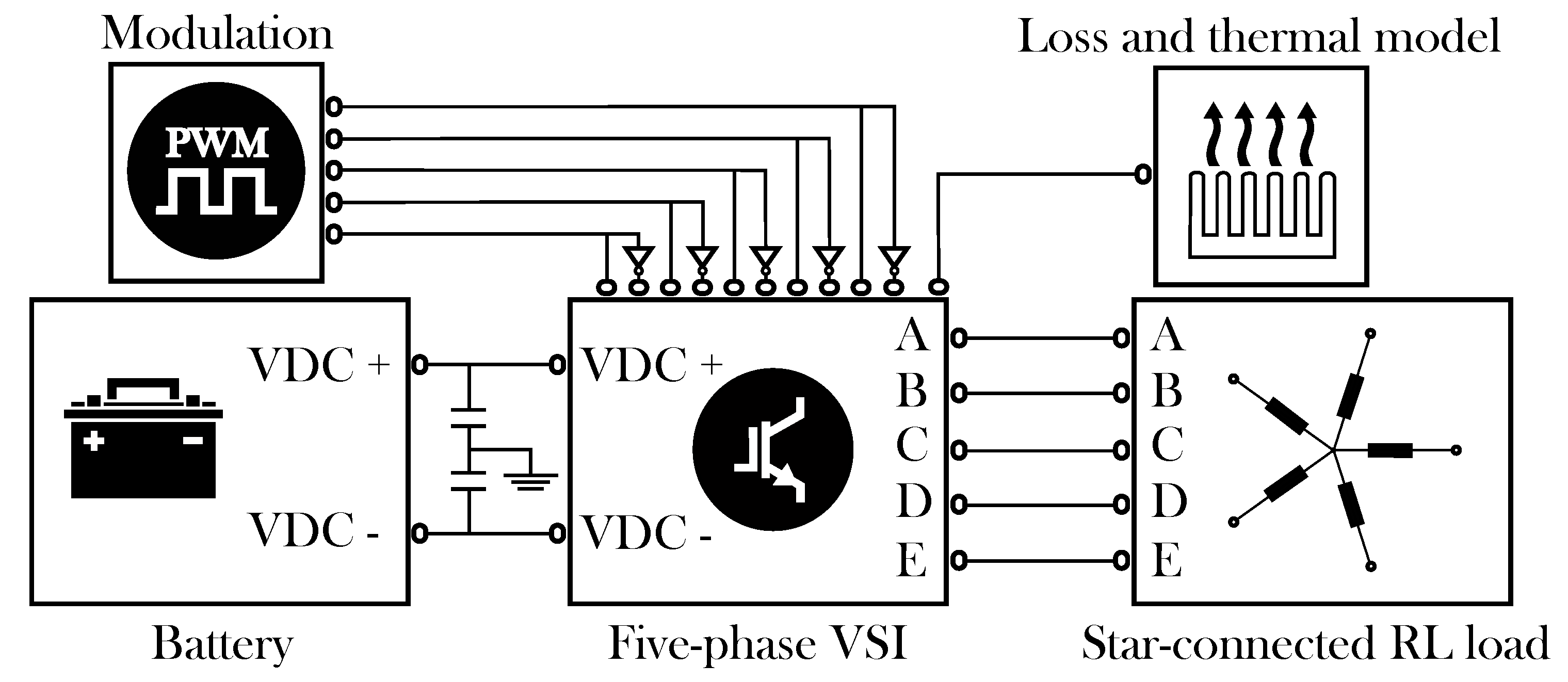
Figure 8 shows the open-loop model block diagram. SimPowerSystem blocks have been used to model the power elements. The battery has been modeled as an ideal DC voltage source. The power-converter block includes a two-level five-phase voltage source inverter, where each switching device includes a detailed loss and thermal model, allowing an accurate estimation of inverter losses. In this work, a loss model of the International Rectifier AUIRGPS4067D1 IGBT has been implemented for each switch, whose main parameters are detailed in Table 5. The loss and thermal model follows the same approach as the one presented by the authors in [50]. The analytical approach used in this work to estimate the instantaneous conduction and switching losses is commonly used by the scientific community [51] and by the industry [52]. On the other hand, the adopted 1D thermal modeling approach has been verified by the authors in [53], where it has been compared to 3D finite element method (FEM) simulation, obtaining almost the same results. Finally, a passive star-connected five-phase RL load has been included. The most significant parameters of the open-loop model are collected in Table 6.
Figure 9 shows the THD and the efficiencies obtained for the proposed algorithm and for other techniques for all the linear range. As it was expected, RCMV-PWM modulations show greater harmonic content when compared to SV-PWM due to the use of phase-opposite vectors. However, for high modulation index values, all the studied modulations produce a similar THD. On the other hand, while AZSL2M2-PWM and SV-PWM have similar efficiencies, the HAZSL5M5-PWM has a slightly lower efficiency, which increases for low modulation indexes.
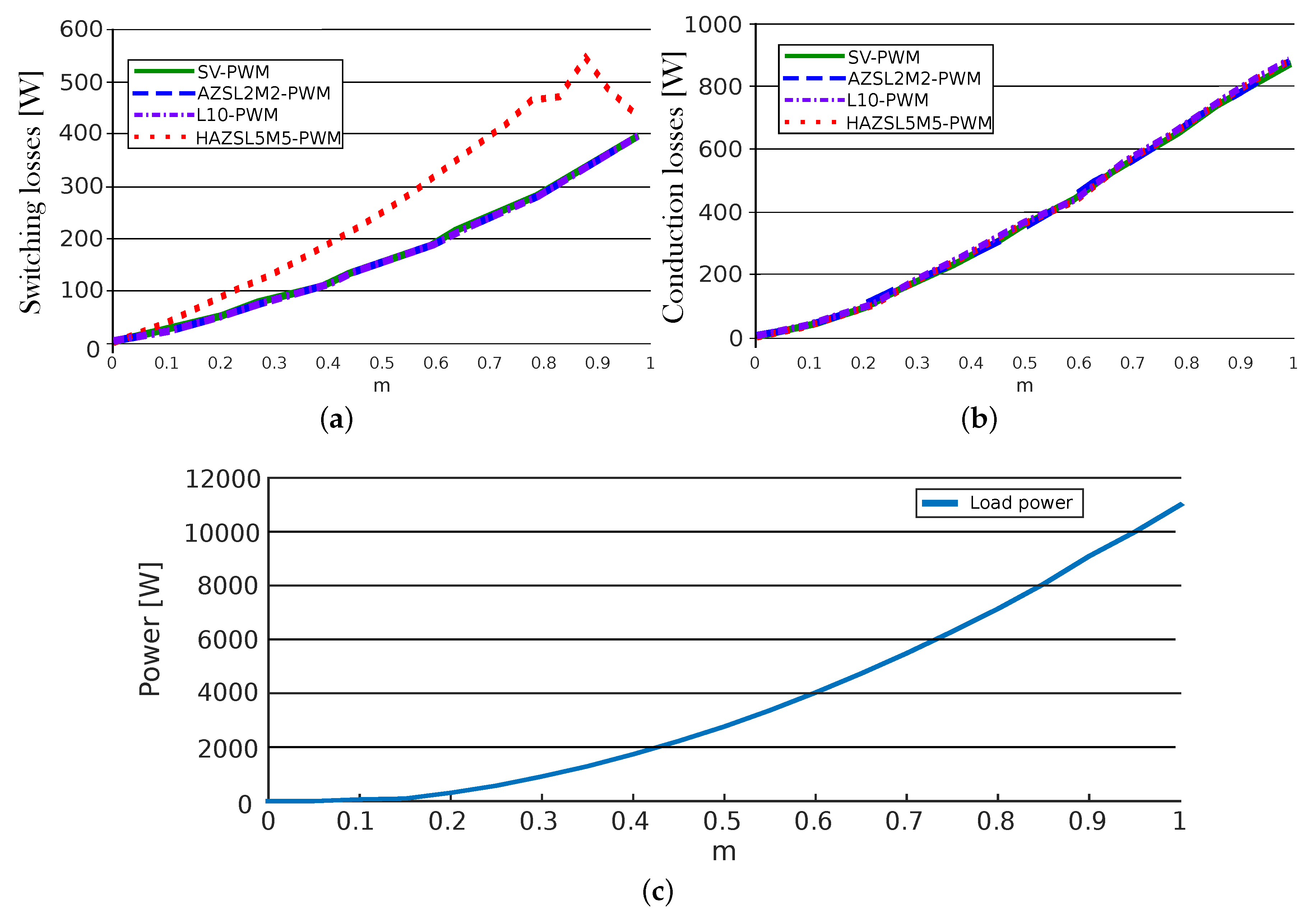
Power losses can be seen in more detail in Figure 10. As mentioned before, HAZSL5M5-PWM requires more commutations at each vector change which entails an increase of switching losses (Figure 10a). However, conduction losses are almost equal in all modulations (Figure 10b). On the other hand, Figure 10c shows the load power as a function of the modulation index.
Regarding CMV mitigation, the proposed HAZSL5M5-PWM technique reduces Δ C M V and N C M V by a 60% and 80%, respectively, when m 0.8507 . These percentages are reduced while m gets close to 1. The worst case scenario, when modulation index is 1, AZSL5M5-PWM is active 29.78% of the simulated time while SV-PWM is active the 70.22% of the simulated time. In such a case, the Δ C M V is reduced by 17.86% and N C M V is reduced by 23.82%. In addition, when applying the operation condition equivalent to maximum torque ( T e m m a x = 26 Nm) and maximum speed ( ω m a x = 105 rpm) that allows this particular application (modulation index = 0.96), AZSL5M5-PWM is active 49.8% of the simulated time while SV-PWM is active the 50.2% of the simulated time, reducing the Δ C M V by 29.88% and N C M V by 39.84%. So, even when the most torque and speed values are considered, HAZSL5M5-PWM reduces the N C M V as much as AZSL2M2-PWM and L10-PWM techniques.

5.2. EMA Model Simulation Results

Figure 11 shows the block diagram of the implemented EMA model where, as in the open-loop model, the same power loss model based on the International Rectifier AUIRGPS4067D1 IGBT has been implemented. The EMA incorporates a star-connected five-phase PMSM, which third harmonic back-EMF component is negligible. Table 7 shows the main parameters of the simulated EMA.
The five-phase PMSM stator voltages are given by:
V = RI + L d I d t + d Ψ P M d t ,
where V and I are five-dimensional vectors whose element ( v j and i j , j [ a , b , , e ] ) are the per-phase voltages and currents, respectively. R is a 5 × 5 diagonal matrix, where each diagonal element represents the phase resistance. L is the 5 × 5 stator inductance matrix, where each element L i j ( i , j [ a , b , , e ] ) represent the self- ( i = j ) and mutual-inductances ( i j ) between phases i and j. Being the value of the mutual-inductances very low and magnetic saturation phenomena negligible, mutual-inductances have been considered zero and self-inductances have been considered constant in the implemented electric machine model. A perfectly balanced stator has been considered. These assumptions have been done without losing generality for the evaluation of the proposed modulation algorithm as, if any non-ideality is present in the electric drive, torque and speed loops are responsible of their compensation, while the proposed algorithm synthesizes the commanded reference voltages and minimizes CMV. The term Ψ P M is the five-dimensional flux linkage vector ( Ψ P M = [ Ψ P M a , Ψ P M b , , Ψ P M e ] T ) produced due to the permanent magnets.
The torque produced by the motor is given by:
T e m = I T d Ψ P M d θ m ,
where θ m is the angular mechanical rotor position. The dynamics of the rotational movement are given by:
T e m T l = J d ω m d t + B ω m ,
where T l is the load torque produced by the EMA, J is the total inertia moment of the rotating masses, including EMA and motor, ω m is the rotational speed of the rotor and B is the viscous friction coefficient.
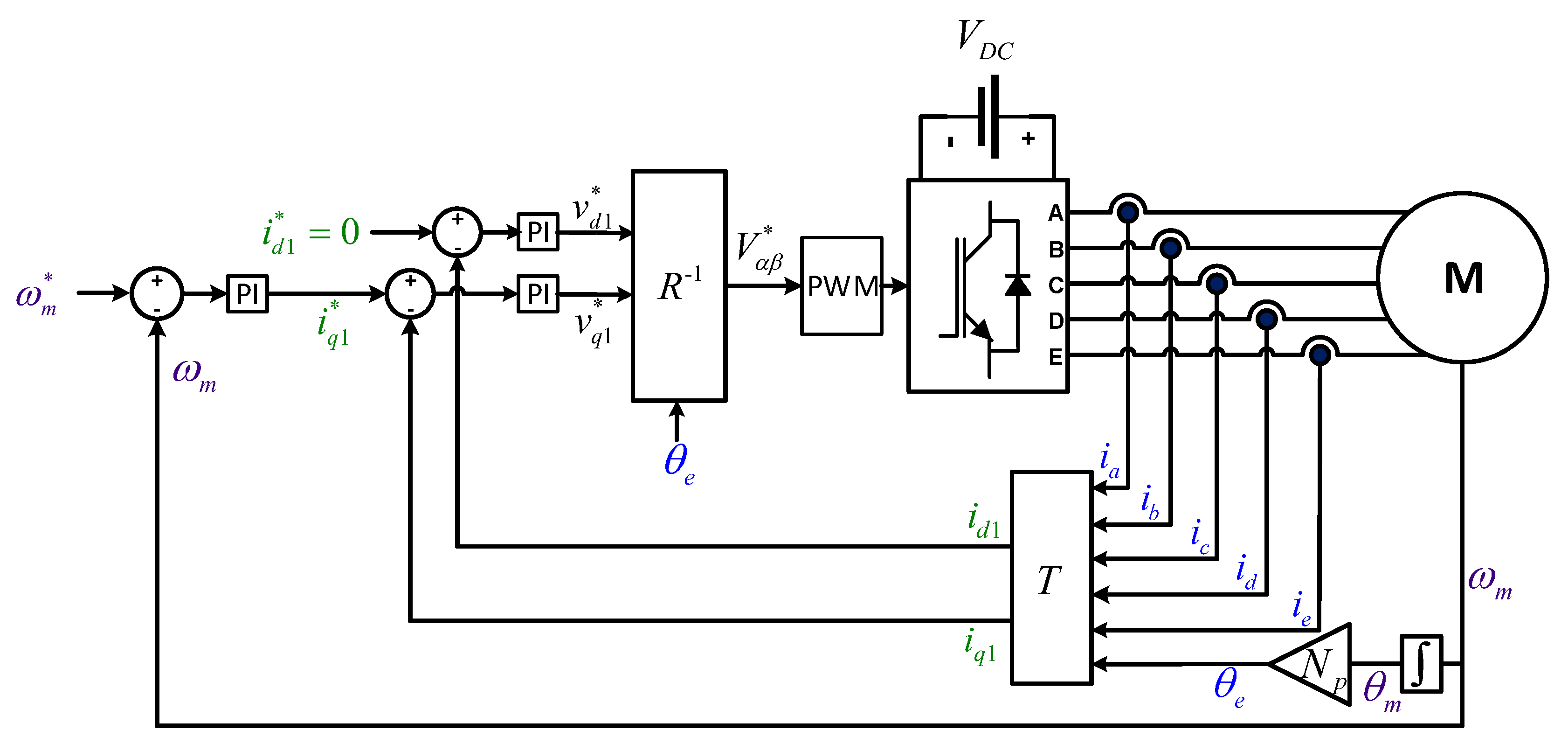
Figure 12 shows the detailed diagram of the controller. The controller consists of two control loops. The outer one regulates the rotational speed of the motor. This loop has a proportional-integral (PI) controller tuned in z. For this application, the damping factor has been set to ξ = 0.707 , while the settling-time has been set to T s = 50 ms. The inner loop tracks the current references through a vector controller [54]. Again, ξ = 0.707 for the current regulator, while T s = 5 ms. In this particular case, only two PI controllers are required to control the first harmonic components ( i d 1 , i q 1 ), as there is no third harmonic back-EMF component and the proposed PWM technique intrinsically regulates to zero the third harmonic voltages ( V x * and V y * are imposed to be zero). It must be taken into account that, for this particular control approach, a conventional microcontroller sine-triangle PWM peripheral cannot be used due to the modulation algorithm computational requirements. Thus, an FPGA should be incorporated to implement the modulation algorithm, while implementing the speed and current loops in a fixed-point or floating point DSP.
Therefore, the following a b c d e to d 1 - q 1 transformation (T) is used in the controller:
T = 2 5 c o s ( θ e ) c o s ( θ e 2 π / 5 ) c o s ( θ e 4 π / 5 ) c o s ( θ e 6 π / 5 ) c o s ( θ e 8 π / 5 ) s i n ( θ e ) s i n ( θ e 2 π / 5 ) s i n ( θ e 4 π / 5 ) s i n ( θ e 6 π / 5 ) s i n ( θ e 8 π / 5 ) ,
this being the matrix product of the transformation in (1) with the following rotational matrix:
R = c o s ( θ e ) s i n ( θ e ) 0 0 0 s i n ( θ e ) c o s ( θ e ) 0 0 0 ,
where θ e is the electrical rotor position of the motor, being θ e = N p θ m .
Once the inner loop PI controllers provide the voltage references ( v d 1 * , v q 1 * ), such references are transformed into the α β frame by applying the R 1 (pseudo-inverse of R) matrix and fed to the PWM block. Matrix R 1 is the classical counter-clockwise rotation transformation [42]:
R 1 = c o s ( θ e ) s i n ( θ e ) s i n ( θ e ) c o s ( θ e ) ,
Several simulations have been performed for various torque and speed conditions that cover the whole operation range of the EMA in order to evaluate the figures of the HAZSL5M5-PWM algorithm compared to other techniques.
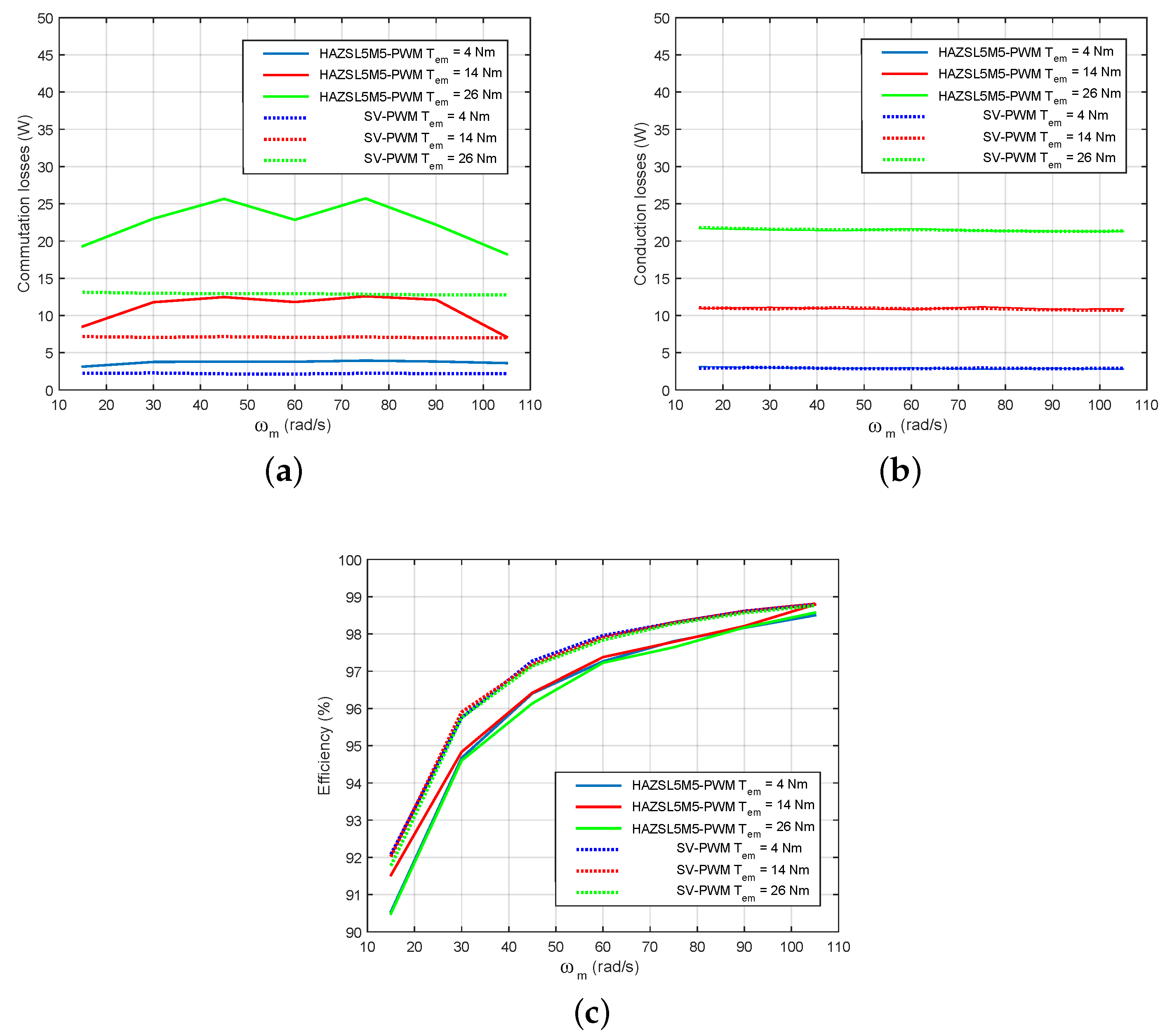
Figure 13a–c show the efficiency results and the distribution between conduction and switching losses. Similar results as in open-loop simulations have been obtained for the EMA platform. As expected, switching losses increase when applying HAZSL5M5-PWM. However, such losses are not linear since hybrid AZSL5M5-PWM also includes SV-PWM algorithm and, when high modulation indexes are required, SV-PWM and HAZSL5M5-PWM techniques operate together reducing commutation losses. In terms of overall system efficiency, it is only reduced for about 1% when compared HAZSL5M5-PWM to SV-PWM. However, Δ C M V and N C M V are significantly reduced thanks to the proposed technique. In addition, in this particular application, AZSL5M5-PWM is operating all the time in all the simulated operation points except the one described in the previous section ( T e m = 26 Nm and ω = 105 rpm). Consequently, the benefits of the AZSL5M5-PWM are fully exploited in the vast majority of the operation points of this application.

6. Conclusions

This paper introduces the CMV issue in multiphase electric drives and, more precisely, in EMA drives for MEA applications. In this context, the HAZSL5M5-PWM modulation technique is proposed. The basis of this technique merges the usage of phase-opposite vectors and the use of only odd or even active vectors to further reduce the CMV. The THD and efficiency characteristics of the proposed RCMV-PWM algorithm are evaluated and compared with SV-PWM and other RCMV-PWM techniques in an open-loop and in an EMA drive Simulink models. It is shown that the proposed algorithm achieves better THD performance when high modulation indexes are required. In addition, this technique reduces CMV variations ( N C M V ) up to 80% when compared to SV-PWM, which directly implies a reduction in the leakage currents that affect the bearings. Therefore, the EMA reliability is improved. In exchange, with the proposed modulation the system efficiency slightly decreases. Thus, the investigation of other hybridization alternatives for the HAZSL5M5-PWM modulation technique that also consider THD and efficiency can be considered for future research.

Author Contributions

M.F. concept for the article, writing, proposed modulation technique development, open-loop and closed-loop models simulations and analysis. A.S.-G. EMA model development and support on closed-loop model simulations. E.R. IGBT and thermal model development, support on open-loop simulations and review. I.K. support on modulation technique development, conceptual support, review and supervision. E.I. simulation platform development, review and supervision. J.L.M. review. All authors have read and agreed to the published version of the manuscript.

Funding

This work has been supported in part by the Government of the Basque Country within the fund for research groups of the Basque University system IT978-16 and in part by the Government of the Basque Country within the research program ELKARTEK as the project ENSOL (KK-2018/00040).

Conflicts of Interest

The authors declare no conflict of itnerest.

Abbreviations

The following abbreviations are used in this manuscript:
ACAlternating current
AZS-PWMActive Zero-State Pulse Width Modulation
AZSL2M2-PWMActive Zero-State Two Large Two Medium
AZSL4-PWMActive Zero-State Four Large
AZSL5M5-PWMActive Zero-State Five Large Five Medium
CMCCommon mode current
CMVCommon mode voltage
DCDirect current
EDMElectric discharge machining
EMAElectromechanical actuator
EMIElectromagnetic interferences
FEMFinite element method
GaNGallium nitride
HVDCHigh-voltage direct current
IGBTInsulated gate bipolar transistor
L5-PWMFive Large Pulse Width Modulation
L10-PWMTen Large Pulse Width Modulation
M5-PWMFive Medium Pulse Width Modulation
M10-PWMTen Medium Pulse Width Modulation
MEAMore Electric Aircrafts
PIProportional Integral
PMSMPermanent Magnet Synchronous Machine
PWMPulse Width Modulation
RCMV-PWMReduced Common Mode Voltage Pulse Width Modulation
SiCSilicon Carbide
SV-PWMSpace Vector Pulse Width Modulation
THDTotal Harmonic Distortion
VSIVoltage Source Inverter
WBGWide Bandgap

References

  1. Uzhegov, N.; Smirnov, A.; Park, C.H.; Ahn, J.H.; Heikkinen, J.; Pyrhönen, J. Design Aspects of High-Speed Electrical Machines with Active Magnetic Bearings for Compressor Applications. IEEE Trans. Ind. Electron. 2017, 64, 8427–8436. [Google Scholar] [CrossRef]
  2. Riba, J.R.; López-Torres, C.; Romeral, L.; Garcia, A. Rare-earth-free propulsion motors for electric vehicles: A technology review. Renew. Sustain. Energy Rev. 2016, 57, 367–379. [Google Scholar] [CrossRef] [Green Version]
  3. Kumar, M.S.; Revankar, S.T. Development scheme and key technology of an electric vehicle: An overview. Renew. Sustain. Energy Rev. 2017, 70, 1266–1285. [Google Scholar] [CrossRef]
  4. Riveros, J.A.; Barrero, F.; Levi, E.; Durán, M.J.; Toral, S.; Jones, M. Variable-Speed Five-Phase Induction Motor Drive Based on Predictive Torque Control. IEEE Trans. Ind. Electron. 2013, 60, 2957–2968. [Google Scholar] [CrossRef]
  5. Negahdari, A.; Yepes, A.G.; Doval-Gandoy, J.; Toliyat, H.A. Efficiency Enhancement of Multiphase Electric Drives at Light-Load Operation Considering Both Converter and Stator Copper Losses. IEEE Trans. Power Electron. 2019, 34, 1518–1525. [Google Scholar] [CrossRef]
  6. Liu, Z.; Li, Y.; Zheng, Z. A review of drive techniques for multiphase machines. CES Trans. Electr. Mach. Syst. 2018, 2, 243–251. [Google Scholar] [CrossRef]
  7. Diana, M.; Ruffo, R.; Guglielmi, P. PWM Carrier Displacement in Multi-N-Phase Drives: An Additional Degree of Freedom to Reduce the DC-Link Stress. Energies 2018, 11, 443. [Google Scholar] [CrossRef] [Green Version]
  8. Zheng, P.; Sui, Y.; Zhao, J.; Tong, C.; Lipo, T.A.; Wang, A. Investigation of a Novel Five-Phase Modular Permanent-Magnet In-Wheel Motor. IEEE Trans. Magn. 2011, 47, 4084–4087. [Google Scholar] [CrossRef]
  9. Cao, W.; Mecrow, B.C.; Atkinson, G.J.; Bennett, J.W.; Atkinson, D.J. Overview of Electric Motor Technologies Used for More Electric Aircraft (MEA). IEEE Trans. Ind. Electron. 2012, 59, 3523–3531. [Google Scholar] [CrossRef]
  10. Bozhko, S.; Hill, C.I.; Yang, T. More-Electric Aircraft: Systems and Modeling. In Wiley Encyclopedia of Electrical and Electronics Engineering; American Cancer Society: New York, NY, USA, 2018; pp. 1–31. [Google Scholar] [CrossRef]
  11. Wheeler, P.W.; Clare, J.C.; Trentin, A.; Bozhko, S. An overview of the more electrical aircraft. J. Aerosp. Eng. 2012, 227, 578–585. [Google Scholar] [CrossRef]
  12. Deng, Q.; Wang, Z.; Chen, C.; Czarkowski, D.; Kazimierczuk, M.K.; Zhou, H.; Hu, W. Modeling and Control of Inductive Power Transfer System Supplied by Multiphase Phase-Controlled Inverter. IEEE Trans. Power Electron. 2019, 34, 9303–9315. [Google Scholar] [CrossRef]
  13. Belkhode, S.; Jain, S. Optimized Switching PWM Technique With Common-Mode Current Minimization for Five-Phase Open-End Winding Induction Motor Drives. IEEE Trans. Power Electron. 2019, 34, 8971–8980. [Google Scholar] [CrossRef]
  14. Liu, Z.; Zheng, Z.; Xu, L.; Wang, K.; Li, Y. Current Balance Control for Symmetrical Multiphase Inverters. IEEE Trans. Power Electron. 2016, 31, 4005–4012. [Google Scholar] [CrossRef]
  15. Prieto, B. Design and Analysis of Fractional-Slot Concentrated-Winding Multiphase Fault-Tolerant Permanent Magnet Synchronous Machines. Ph.D. Thesis, Tecnum Universidad de Navarra, Donostia, Spain, 2015. [Google Scholar]
  16. Iqbal, A.; Rahman, K.; Abdallah, A.A.; Moin, K.A.S.; Abdellah, K. Current Control of a Five-phase Voltage Source Inverter. In Proceedings of the International Conference on Power Electronics and their Applications (ICPEA), Elazig, Turkey, 27 September 2013. [Google Scholar]
  17. Bennett, J.W.; Atkinson, G.J.; Mecrow, B.C.; Atkinson, D.J. Fault-Tolerant Design Considerations and Control Strategies for Aerospace Drives. IEEE Trans. Ind. Electron. 2012, 59, 2049–2058. [Google Scholar] [CrossRef]
  18. Bojoi, R.; Cavagnino, A.; Tenconi, A.; Tessarolo, A.; Vaschetto, S. Multiphase electrical machines and drives in the transportation electrification. In Proceedings of the IEEE 1st International Forum on Research and Technologies for Society and Industry Leveraging a better tomorrow (RTSI), Torino, Italy, 18 September 2015. [Google Scholar] [CrossRef]
  19. Takahashi, S.; Ogasawara, S.; Takemoto, M.; Orikawa, K.; Tamate, M. Common-Mode Voltage Attenuation of an Active Common-Mode Filter in a Motor Drive System Fed by a PWM Inverter. IEEE Trans. Ind. Appl. 2019, 55, 2721–2730. [Google Scholar] [CrossRef]
  20. Karampuri, R.; Jain, S.; Somasekhar, V.T. Common-Mode Current Elimination PWM Strategy Along with Current Ripple Reduction for Open-Winding Five-Phase Induction Motor Drive. IEEE Trans. Power Electron. 2019, 34, 6659–6668. [Google Scholar] [CrossRef]
  21. Espina, J.; Balcells, J.; Arias, A.; Ortega, C. Common mode EMI model for a direct matrix converter. IEEE Trans. Ind. Electron. 2011, 58, 5049–5056. [Google Scholar] [CrossRef]
  22. Muetze, A.; Binder, A. Don’t lose your bearings. IEEE Ind. Appl. Mag. 2006, 12, 22–31. [Google Scholar] [CrossRef]
  23. Hadden, T.; Jiang, J.W.; Bilgin, B.; Yang, Y.; Sathyan, A.; Dadkhah, H.; Emadi, A. A Review of Shaft Voltages and Bearing Currents in EV and HEV Motors. In Proceedings of the Industrial Electronics Society (IECON), Florence, Italy, 24 October 2016; pp. 1578–1583. [Google Scholar]
  24. Mütze, A. Thousands of hits: On inverter-induced bearing currents, related work, and the literature. Elektrotechnik Inf. 2011, 128, 382–388. [Google Scholar] [CrossRef]
  25. Muetze, A. On a New Type of Inverter-Induced Bearing Current in Large Drives With One Journal Bearing. IEEE Trans. Ind. Appl. 2010, 46, 240–248. [Google Scholar] [CrossRef]
  26. Morya, K.; Gardner, M.C.; Anvari, B.; Liu, L.; Yepes, A.G.; Doval-Gandoy, J.; Toliyat, H.A. Wide Bandgap Devices in AC Electric Drives: Opportunities and Challenges. IEEE Trans. Transp. Electrif. 2019, 5, 3–20. [Google Scholar] [CrossRef]
  27. Oh, W.; Willwerth, A. Shaft Grounding—A Solution to Motor Bearing Currents. Am. Soc. Heating Refrig. Air Cond. Eng. Trans. 2008, 114, 246–251. [Google Scholar]
  28. Muetze, A.; Binder, A. Calculation of influence of insulated bearings and insulated inner bearing seats on circulating bearing currents in machines of inverter-based drive systems. IEEE Trans. Ind. Appl. 2006, 42, 965–972. [Google Scholar] [CrossRef]
  29. Muetze, A. Bearing Currents in Inverter-Fed AC-Motors. Ph.D. Thesis, Der Technischen Universitaet Darmstadt, Darmstadt, Germany, 2004. [Google Scholar]
  30. Schiferl, R.F.; Melfi, M.J. Bearing current remediation options. IEEE Ind. Appl. Mag. 2004, 10, 40–50. [Google Scholar] [CrossRef]
  31. Muetze, A.; Oh, W. Application of Static Charge Dissipation to Mitigate Electric Discharge Bearing Currents. IEEE Trans. Ind. Appl. 2008, 44, 135–143. [Google Scholar] [CrossRef]
  32. Nguyen, N.; Nguyen, T.; Lee, H. A reduced siwtching loss PWM strategy to eliminate common-mode voltage in multilevel inverters. IEEE Trans. Power Electron. 2015, 30, 5425–5438. [Google Scholar] [CrossRef]
  33. Syed, A.; Kalyani, S. Evaluation of single phase transformerless photovoltaic inverters. Electr. Electron. Eng. Int. J. 2015, 4, 25–39. [Google Scholar] [CrossRef]
  34. Freddy, T.K.S.; Rahim, N.A.; Hew, W.P.; Che, H.S. Comparison and Analysis of Single-Phase Transformerless Grid-Connected PV Inverters. IEEE Trans. Power Electron. 2014, 29, 5358–5369. [Google Scholar] [CrossRef]
  35. Freddy, T.K.S.; Rahim, N.A.; Hew, W.P.; Che, H.S. Modulation Techniques to Reduce Leakage Current in Three-Phase Transformerless H7 Photovoltaic Inverter. IEEE Trans. Ind. Electron. 2015, 62, 322–331. [Google Scholar] [CrossRef]
  36. Kouro, S.; Leon, J.I.; Vinnikov, D.; Franquelo, L.G. Grid-Connected Photovoltaic Systems: An Overview of Recent Research and Emerging PV Converter Technology. IEEE Ind. Electron. Mag. 2015, 9, 47–61. [Google Scholar] [CrossRef]
  37. Fernandez, M.; Robles, E.; Kortabarria, I.; Andreu, J.; Ibarra, E. Novel modulation techniques to reduce the common mode voltage in multiphase inverters. In Proceedings of the IEEE Industrial Electronics Society Conference (IECON), Lisabon, Portugal, 14 October 2019; pp. 1898–1903. [Google Scholar]
  38. Durán, M.J.; Prieto, J.; Barrero, F.; Riveros, J.A.; Guzman, H. Space-Vector PWM with Reduced Common-Mode Voltage for Five-Phase Induction Motor Drives. IEEE Trans. Ind. Electron. 2013, 60, 4159–4168. [Google Scholar] [CrossRef]
  39. Rahman, A. Power Electronics and Motor Drives; CRC Press: Boca Raton, FL, USA, 2016; pp. 5–10. [Google Scholar]
  40. Gray, R. Toeplitz and Circulant Matrices: A Review. Found. Trends Commun. Inf. Theory 2006, 2, 155–239. [Google Scholar] [CrossRef]
  41. Semail, E.; Bouscayrol, A.; Hautier, P.J. Vectorial formalism for analysis and design of polyphase synchronous machines. Eur. Phys. J. Appl. Phys. 2003, 22, 207–220. [Google Scholar] [CrossRef] [Green Version]
  42. Tang, K.T. Mathematical Methods for Engineers and Scientists 1; Springer: Berlin, Germany, 2006. [Google Scholar]
  43. Davis, P. Circulant Matrices; John Wiley & Sons Inc.: Hoboken, NJ, USA, 1979. [Google Scholar]
  44. Zhar, H.; Gong, J.; Semail, E.; Scuiller, F. Comparison of Optimized Control Strategies of a High-speed Traction Machine with Five Phases and Bi-Harmonic Electromotive Force. Energies 2016, 9, 952. [Google Scholar] [CrossRef] [Green Version]
  45. Kelly, W.; Strangas, E.G.; Miller, J.M. Multiphase Space Vector Pulse Width Modulation. IEEE Power Eng. Rev. 2002, 22, 53. [Google Scholar] [CrossRef]
  46. Iqbal, A.; Levi, E. Space vector modulation schemes for a five-phase voltage source inverter. In Proceedings of the European Conference on Power Electronics and Applications (ECPEA), Barcelona, Spain, 10 September 2005; pp. 1–12. [Google Scholar] [CrossRef]
  47. Yen-Shin, L.; Po-Sheng, C.; Hsiang-Kuo, L.; Chou, J. Optimal common-mode voltage reduction PWM technique for inverter control with consideration of the dead-time effects-part II: Applications to IM drives with diode front end. IEEE Trans. Ind. Appl. 2004, 40, 1613–1620. [Google Scholar] [CrossRef]
  48. Iqbal Alammari, R.; Mosa, M.; Abu-Rub, H. Finite set model predictive current control with reduced and constant common mode voltage for a five-phase voltage source inverter. In Proceedings of the International Symposium on Industrial Electronics (ISIE), Istambul, Turkey, 4 June 2014; pp. 479–484. [Google Scholar] [CrossRef]
  49. Munim, N.A.; Ismail, M.F.; Abidin, A.F.; Haris, H.M. Multi-phase inverter Space Vector Modulation. In Proceedings of the International Power Engineering and Optimization Conference (PEOCO), Langkawi, Malaysia, 22 July 2013; pp. 149–154. [Google Scholar] [CrossRef]
  50. Robles, E.; Fernandez, M.; Ibarra, E.; Andreu, J.; Kortabarria, I. Mitigation of Common Mode Voltage Issues in Electric Vehicle Drive Systems by Means of an Alternative AC-Decoupling Power Converter Topology. Energies 2019, 12, 3349. [Google Scholar] [CrossRef] [Green Version]
  51. Sadigh, A.K.; Dargahi, V.; Corzine, K. Analytical determination of conduction power loss and investigation of switching power loss for modified flying capacitor multicell converters. IET Power Electron. 2016, 9, 175–187. [Google Scholar] [CrossRef]
  52. Wintrich, A.; Nicolai, U.; Tursky, W.; Reimann, T. Application Manual Power Semiconductors; Semikron: Nürnberg, Germany, 2017. [Google Scholar]
  53. Matallana, A.; Robles, E.; Ibarra, E.; Andreu, J.; Delmonte, N.; Cova, P. A methodology to determine reliability issues in automotive SiC power modules combining 1D and 3D thermal simulations under driving cycle profiles. Microelectron. Reliab. 2019, 102, 1–9. [Google Scholar] [CrossRef]
  54. Parsa, L.; Toliyat, H. Five-Phase Permanent-Magnet Motor Drives. IEEE Trans. Ind. Appl. 2005, 41, 30–37. [Google Scholar] [CrossRef]
Figure 1. CMV in a five-phase power system.
Energies 13 00607 g001
Figure 2. Cause-and-effect chain of common mode voltage (CMV) (adapted from [25]).
Energies 13 00607 g002
Figure 3. Five-phase SV-PWM: α - β and x-y planes with their corresponding space vectors and switching states (a ‘1’ in a switching state represents that the top switch of a given phase is activated, while a ‘0’ represents that its complementary switch is activated). (a) α - β vector plane. (b) x-y vector plane.
Energies 13 00607 g003
Figure 4. CMV waveform of SV-PWM technique (adapted from [23]).
Energies 13 00607 g004
Figure 5. Sector distribution of AZSL5M5-PWM modulation scheme in the α - β plane. (a) AZSL5M5-PWM implemented with odd vectors. (b) AZSL5M5-PWM implemented with even vectors.
Energies 13 00607 g005
Figure 6. AZSL5M5-PWM modulation vector sequence (①–⑥) for sector 1 when only odd vectors are applied.
Energies 13 00607 g006
Figure 7. HAZSL5M5-PWM. White: AZSL5M5-PWM with odd vectors; shadowed: AZSL5M5-PWM with even vectors; lines: SV-PWM.
Energies 13 00607 g007
Figure 8. Block diagram of the constituting parts of the open-loop Simulink model.
Energies 13 00607 g008
Figure 9. Total harmonic distortion (THD) and efficiency of studied modulation techniques for static operation points. (a) THD. (b) Efficiency.
Energies 13 00607 g009
Figure 10. Distribution of power losses for the of studied modulation techniques for static operation points. (a) Switching losses. (b) Conduction losses. (c) Load power.
Energies 13 00607 g010
Figure 11. General block diagram of the electromechanical actuator (EMA) simulation platform.
Energies 13 00607 g011
Figure 12. Block diagram of the EMA speed and torque controller.
Energies 13 00607 g012
Figure 13. Power losses and efficiency of the proposed HAZSL5M5-PWM algorithm compared to other modulation techniques. (a) EMA switching losses for the studied modulation techniques. (b) EMA conduction losses for the studied modulation techniques. (c) EMA system efficiency with for the studied modulation techniques.
Energies 13 00607 g013
Table 1. Sub-space harmonics mapping for a five-machine.
Sub-SpaceHarmonics
α β h = 1 , 9 , 11 , 19
x y h = 3 , 7 , 13 , 17
zero-sequence h = 0 , 5 , 15 , 25
Table 2. Summary of the most relevant features of SV-PWM and RCMV-PWM techniques.
Modulation Δ CMV [V] N CMV Δ CMV Reduction [%] N CMV Reduction [%] v CM WaveformLinear Range
SV-PWM V D C 10-- Energies 13 00607 i001 0 m 1
AZSL2M2-PWM0.6 V D C 6−40%−40% Energies 13 00607 i002 0 m 1
AZSL4-PWM0.2 V D C 10−80%0% Energies 13 00607 i003 0 m 1
M5-PWM00−100%−100% Energies 13 00607 i004 0 m 0.5257
M10-PWM0.6 V D C 2−40%−80% Energies 13 00607 i005 0 m 0.618
L5-PWM00−100%−100% Energies 13 00607 i006 0 m 0.8507
L10-PWM0.2 V D C 6−80%−40% Energies 13 00607 i007 0 m 1
AZSL5M5-PWM0.4 V D C 2−60%−80% Energies 13 00607 i008 0 m 0.8507
Table 3. Values of M s depending on the α β plane sector.
Sector 1 ( M 1 )Sector 2 ( M 2 )Sector 3 ( M 3 )Sector 4 ( M 4 )Sector 5 ( M 5 )
0.691 0.224 0 1.176 1.118 0.363 0 0.726 0.427 0.588 1.118 0.363 0.691 0.951 0.691 0.224 0.427 0.588 0.691 0.951 0.691 0.951 0.427 0.588 0.691 0.224 0.691 0.951 1.118 0.363 0.427 0.588 0 0.726 1.118 0.363 0 1.176 0.691 0.224
Table 4. AZSL5M5-PWM vector sequences (odd vectors).
AZSL5M5-PWMVector Sequence
Sector 111001 11100 10000 01000 00100 00010 01000 10000 11100 11001
Sector 211100 01110 01000 00100 00010 00001 00100 01000 01110 11100
Sector 301110 00111 00100 00010 00001 10000 00010 00100 00111 01110
Sector 400111 10011 00010 00001 10000 01000 00001 00010 10011 00111
Sector 510011 11001 00001 10000 01000 00100 10000 00001 11001 10011
Table 5. Most relevant parameters of the simulated International Rectifier AUIRGPS4067D1 IGBT.
ParameterValueUnit
Nominal current per switch120A
Maximum blocking voltage600V
Typical IGBT collector-emitter voltage1.7V
Typical diode forward voltage1.7V
Typical IGBT turn-on switching loss8.2mJ
Typical IGBT turn-off switching loss2.9mJ
Typical diode reverse recovery2.4mJ
IGBT thermal resistance0.2°C/W
Diode thermal resistance0.25°C/W
Allowable junction temperature−55 to 175°C
Table 6. The most significant parameters of the open-loop simulation platform.
VariableSymbolValueUnit
Load resistance R L o a d 0.001 Ω
Load inductance L L o a d 1mH
Battery voltage V D C 320V
Modulator frequency f m o d 50Hz
Switching frequency f s w 10,000Hz
Table 7. Most significant parameters of the simulated EMA.
ParameterSymbolValueUnit
Rated power P n o m 1.51kW
Rated torque T n o m 12.1Nm
Rated speed ω n o m 1200RPM
Pole-pair number N p 9
Stator resistance R s 1.5 Ω
Stator self-inductance L s 9.6mH
PM flux linkage Ψ P M 0.13Wb
HVDC grid voltage V D C 270V
Switching frequency f s w 10,000Hz