1. Introduction
The use of Permanent Magnet Synchronous Machines (PMSMs) has substantially increased in industrial applications, electric traction, renewables energies, etc. due to their superior performance compared with other types of electrical machines, such as Induction Machines (IM), in terms of power density, torque density, dynamic response, wide speed range, simplicity of the control and efficiency. However, the high and often unpredictable price of rare-earth materials and the risk of demagnetisation due to excessive operating currents/temperatures are a concern for this type of machines. Synchronous Reluctance Machines (SynRM) have gained popularity over the last years as a viable alternative thanks to their lower cost and high tolerance to overcurrents and/or overheating and overall increased robustness, resulting from the absence of magnets in the rotor [
1,
2,
3,
4,
5,
6,
7].
Torque production capability of PMSMs depends on the magnetisation state of the permanent magnets (PMs) and the saliency ratio, i.e., the difference between
d- and
q-axes inductances. Magnet strength and inductances can change during normal operation of the machine due to changes in the fundamental current and/or PM temperature [
8,
9,
10]. An increase of the PM temperature reduces the PM remanent flux (i.e., magnetisation state), and consequently the machine torque for a given stator current. In addition, PM remanent flux variation changes the
d-axis saturation level (
d-axis assumed to be aligned with PM flux), and therefore the
d-axis inductance [
11]. Also injection of fundamental current will change the saturation level, resulting therefore into inductance variations [
11,
12]. Torque in SynRMs is function of
d and
q-axes inductances exclusively, which can vary significantly with the current level due to saturation of the core material.
Precise knowledge of the torque produced by the machine is required in many applications. Torque measurement is problematic. Torque transducers based on strain gauges are likely the preferred option [
13,
14,
15,
16,
17]. However, this type of sensor can introduce resonances into the system, are highly sensitive to electromagnetic interference, requires precise mounting and calibration to ensure accuracy and their cost could account for a significant portion of the drive cost [
18]. Less popular options are torque measurement systems based on torsional displacement [
19] or magnetoelastic effect [
20]. Torque measurement systems based on torsional displacement are less sensitive to electromagnetic noise but use optical probes, which are expensive and require accurate calibration [
19]. Torque measurement based on magneto-elastic sensors is simpler and uses non-contact technology without the need of calibration, but it requires special shaft materials and can incur in torque measurement errors due to shaft thermal expansion. Regardless of the method being used, precise torque measurement is expensive, and requires extra elements (sensor, cables, connectors, ...), what can reduce the reliability of the drive. These concerns have boosted the interest in torque estimation methods.
Torque estimation methods can be roughly separated into (a) methods based on the torque equation [
21,
22] and (b) indirect estimation methods [
23,
24,
25,
26,
27,
28,
29,
30,
31]. The first type can use the General Torque Equation (GTE) assuming constant motor parameters [
21], Flux estimation with Compensation Scheme (FCS) where
-flux linkage is estimated by the measurement of stator voltage, currents and rotor position [
21] or look-up-tables, which are used to adjust the machine parameters according to machine operating conditions [
22]. A large number on indirect torque estimation methods have been proposed, which go from a simple power balance with known electric power and rotor speed [
23], observer based methods [
24,
25,
26,
27,
28,
29] (e.g., sliding mode observers [
24], model reference adaptive systems [
25,
26], model reference observers, reduced order observers [
27], recursive least square parameters estimation [
28] or affine projection algorithms parameters estimation [
29]), methods requiring additional sensors, e.g., giant magnetoresistance effect (GMR) based methods [
30], or neural networks based methods [
31]. All these methods [
21,
22,
23,
24,
25,
26,
27,
28,
29,
30,
31] require previous knowledge of certain machine parameters (e.g., resistances or inductances) and/or its operating condition (e.g., temperature).
Injection of a high-frequency (HF) signal has been recently proposed for on-line estimation of the machine parameters used by the torque equation. Consequently, they belong to category (a) discussed above [
12,
32,
33]. The HF signal is injected via inverter on top of the fundamental voltage responsible of torque production, meaning that it does not interfere with the normal operation of the machine. Furthermore, no additional sensors or cabling are needed. The HF signal can be either a current or a voltage signal and have different shapes: pulsating, square-wave, sinusoidal, etc. Although the physical principles are the same in all the cases, this choice can result in significant differences in the implementation. Injection of a voltage signal is easier in principle as the inverter is a voltage source. On the contrary, current injection will require the use of current controllers, but will be shown to improve the reliability of the method. Note that instead of periodic HF signal, PWM pulses could also be used, either transient currents or neutral voltage following each inverter pulse being measured and processed in this case. However, its implementation implies changes in the hardware (e.g., additional sensors, access to the neutral of the machine, etc.), increasing the implementation cost and difficulty.
This paper reviews the use of HF signal injection based parameter estimation methods aimed to improve the accuracy of torque estimation for Interior PMSMs (IPMSMs), Surface PMSMs (SPMSMs) and SynRMs. Pros and cons of each method will be discussed in terms of implementation requirements, accuracy and suitability depending on the machine design. A key aspect for the proposed method will be modelling the relationship between the incremental inductances obtained from the injected HF signal and the apparent inductance used in conventional torque equation. The paper is organised as follows. The fundamental model of the synchronous machine (SM) is presented in
Section 2, while the HF model is presented in
Section 3. Parameter identification and torque estimation using different form of HF signal injections is discussed in
Section 4. Finally, experimental results are provided in
Section 5.
2. Fundamental Model of a Synchronous Motor
The fundamental model of a synchronous machine in a reference frame synchronous with the rotor is given by (
1) [
8], where
,
,
and
are the
d and
q-axes resistances and inductances, respectively;
is the mechanical rotational speed;
is PM flux linkage; and
p is the differential operator. In the nomenclature used in this paper, superscripts
and
indicate the stationary and rotor synchronous reference frames, respectively; subscripts
and
indicate stator and rotor variables, respectively; and subscripts
and
indicate fundamental and HF components respectively. Finally,
is used to indicate commanded values, and
indicates estimated values.
The output torque in the steady state can be expressed by (
2), where
P stands for the number of poles [
19]. The first term on the left-hand side of (
2),
is the electromagnetic/synchronous torque due to the PM flux linking magnet and stator coils, whereas the second term on the right-hand side of (
2),
, is the reluctance torque due to saliency of the machine, i.e., the difference between
d- and
q-axis inductances.
It is observed from (
2) that estimation of the synchronous torque
requires knowledge of
, whereas estimation of the reluctance torque
requires knowledge of the differential inductance (
−
).
As already mentioned, this paper will address torque estimation for three machine designs: IPMSM, SPMSM and SynRM. Their schematic cross sections and main characteristics being shown in
Figure 1 and
Table 1, respectively. From the combined analysis of (
2) and
Table 1, the mechanisms for torque production of each machine design becomes evident.
Torque produced by IPMSMs and SPMSMs is determined both by the magnetic torque due to the PMs (synchronous torque) and the reluctance torque due to different and inductances, i.e., saliency ratio. Note that for the case of SPMSM, the saliency ratio is often negligible. Torque produced by SynRM will be determined only by the saliency ratio. Proper torque estimation will, therefore, require precise estimation of and/or and .
Parameters Variation with Operating Conditions of the Machine
Torque equation is function of inductances and magnet strength, which can change with the operating point of the machine.
q- and
d-axes inductances can be modelled as (
3) and (
4).
From Equation (
3),
q-axis inductance is seen to be function of the fundamental component of the
d-axis current due to cross-coupling, and of the
q-axes current due to saturation [
11]. Similarly,
d-axis inductance (
4) is function of the fundamental
d- and
q-axes currents, but also of the PMs remanent flux, which varies with temperature
[
8,
11,
12]. Variation of
d-axis inductance with PM flux
has been shown to be almost linear, and can therefore be modelled as (
5) [
12], where
and
are the base value of PM flux and
d-axis inductance, i.e., at room temperature (
) and when there is no fundamental current, and
is the
d-axis inductance for a given magnet temperature
and current
.
Substituting (
3)–(
5) into (
2), the general torque equation can be written as (
6), which evidences the dependence of torque with the operating condition of the machine, and highlights the incorrectness of assuming constant inductances. Parameters estimation using HF signal injection is discussed following.
3. HF Model of the Synchronous Machine
The model representing the behaviour of a synchronous machine when the stator is fed at a frequency sufficiently higher than the rotor frequency (
7) can be deduced from (
1) by neglecting magnet flux, as it does not contain any HF component [
12].
As the HF signal being applied is a voltage, Equation (
7) can be solved for the high frequency current as
Torque in Equation (
6) is a function of absolute (apparent) inductances. However, the inductances of the HF model (
7) and (
8) are incremental inductances [
34], i.e., inductances estimated by means of HF signal injection will be incremental. It is needed therefore the establish the relationship between absolute and incremental inductances.
The inductance of a stator winding is defined as the relationship between flux linkage
divided by the stator current
I producing that flux [
35], where
N is the number of turns of the stator winding.
Flux
in the core which can be defined as (
10),
R being the reluctance of the magnetic circuit.
Combining (
9) and (
10), the inductance can be written as (
11), where
is the permeability of the material (
); A is the mean cross-sectional area of the magnetic circuit and
l is the mean length of the magnetic circuit.
It is seen from (
11) that the inductance is proportional to the permeability [
35].
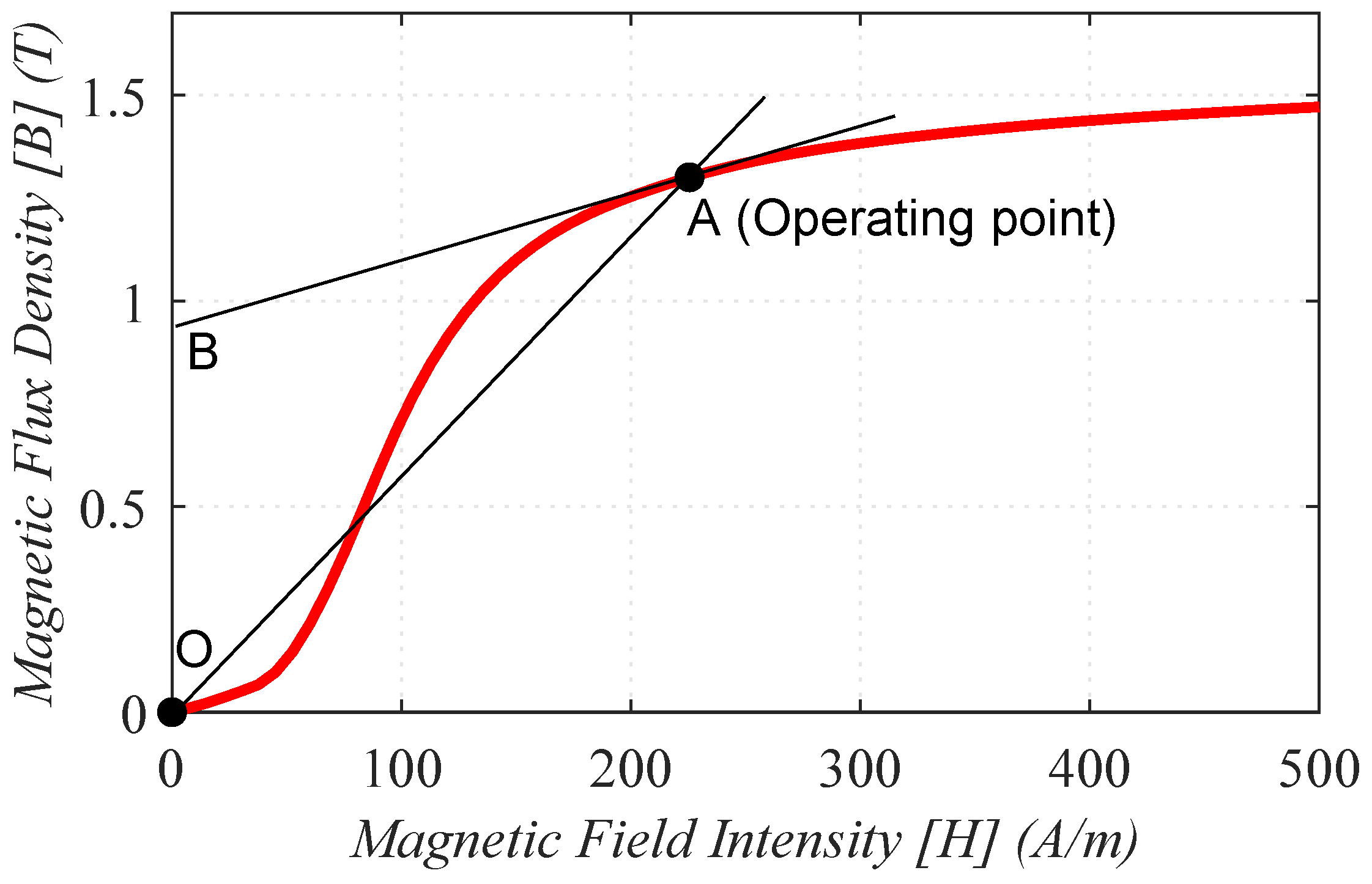
Static and dynamic permeabilities can be used to analyse the B-H curve of ferromagnetic materials (see
Figure 2). The static permeability is defined as the slope of a straight line from the origin to the actual operating point A, i.e., the ratio of flux density (B) vs. field intensity (H) at every operating point (
13). The static permeability gives the absolute inductance of the machine.
On the other hand, the slope (AB) of the B–H curve (
14) is denoted as relative, differential or dynamic permeability.
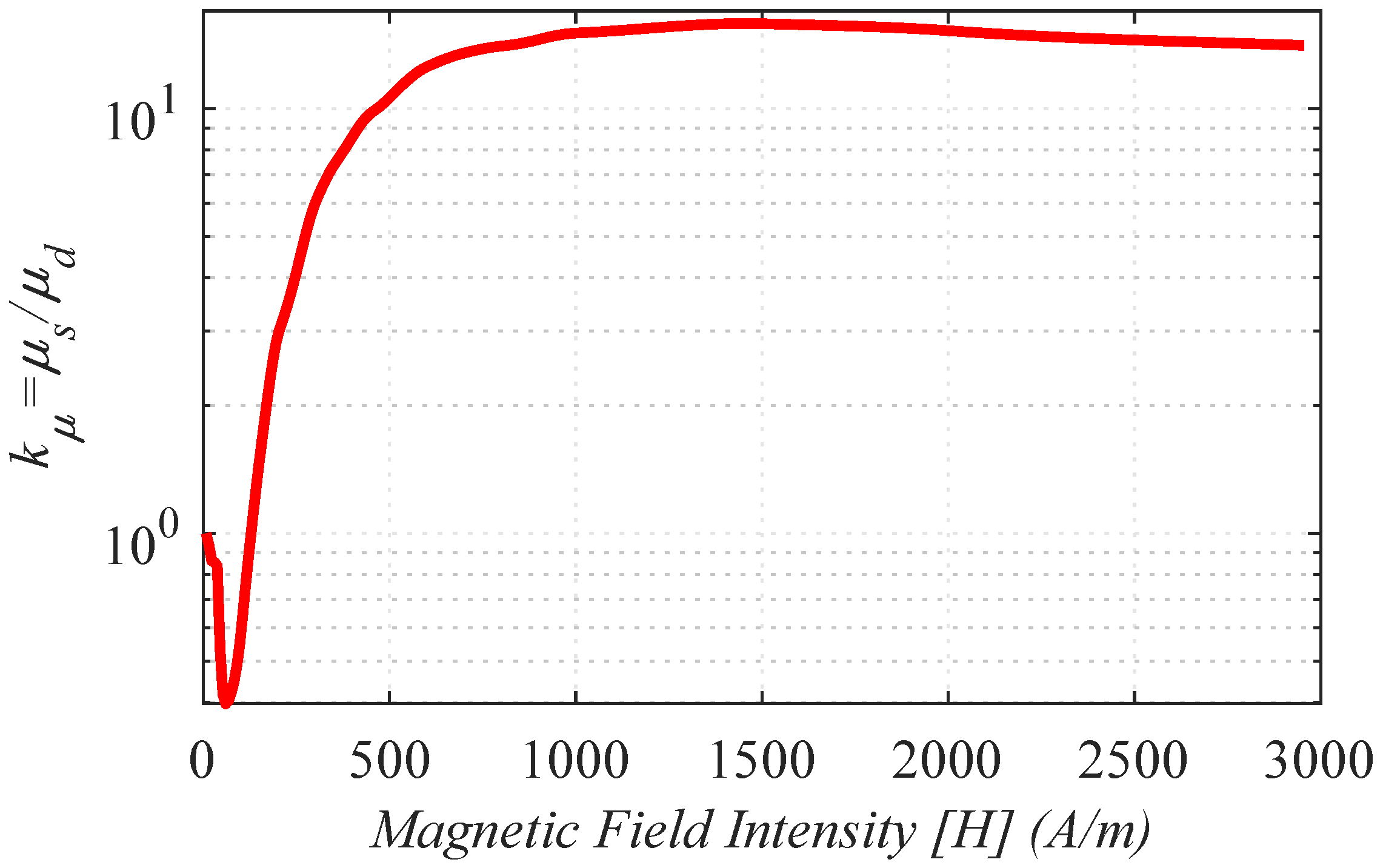
As an example,
Figure 3 shows the BH curve and corresponding static and dynamic permeabilities
and
for the core material NSSMC 50H470. It is observed that for very low excitation levels static and dynamic permeabilities have a ratio close to one, whereas for high current levels the ratio is almost constant (~15 in the figure, note the logarithmic scale). It was deduced from (
12) that absolute and incremental inductances will mirror the behaviour of static and dynamic permeabilities, i.e., the relationship between absolute and incremental inductances can be modeled as (
15), with
being defined as (
16).
It is apparent from
Figure 4 that at high excitation levels, the relationship between both inductances is almost constant. However, to model
in the whole operating range, some type of polynomial function would be needed.
variation shown in (
5) can be therefore rewritten as (
17), the output torque can be finally estimated combining (
15) and (
17) as (
18).
4. HF Inductances Estimation
Different forms of HF excitation can be used to estimate the HF inductances. Generally speaking, voltage injection results in easier implementations as the inverter is a voltage source, but will be sensitive to speed, also being affected by the non-purely inductive machine behaviour. Those drawbacks can be overcome by injecting a HF current, at the price of an increase in the complexity of implementation. Rotating Voltage Injection, Pulsating Voltage Injection and Pulsating -axes Current Injection are discussed in the next subsections, followed by a comparative analysis. It has to be noted that other types of periodic high frequency signal injection (e.g., square wave) could be used. These options have not been discussed in this paper due to room constrains.
4.1. Pulsating Voltage Injection
HF inductances and can be estimated by injecting a voltage HF signal in a predefined direction referred to the d-axes. This form of excitation is commonly referred as pulsating voltage.
The HF model in the synchronous reference frame (
7) can be written as function of the mean
(
20) and differential
(
21) inductances (
19). Note that the resistive component has been neglected, as at high frequency it is significantly smaller than the inductive terms and the
p operator in (
7) has been replaced by
. Furthermore, rotor speed dependent terms in (
7) have been neglected assumed that the HF voltage signal has a frequency much higher than the fundamental rotating frequency (i.e.,
).
The currents induced in the stator terminals expressed in the stator reference frame can be derived from the inverse matrix as (
22)
If a pulsating HF voltage is injected in the stator terminals of the machine (
23), the resulting HF current can be derived substituting in (
23) into (
22) as (
26),
where
is the magnitude of the injected HF signal,
is the phase of the HF signal (
24),
is the frequency of the HF signal,
is the injection angle of the pulsating HF voltage (
25) and
is an arbitrary angle; e.g., if
= 0, the pulsating HF voltage will be injected in the
d-axis of the machine, whereas if
=
/2, it will be injected in the
q-axis.
By synchronization with the injection reference frame
, the stator currents (
26) are transformed into (
27)
Finally, if the HF is injected between
d and
q-axes, i.e.,
, (
27) can be simplified into (
28) [
32]. From (
28) the HF inductances (
29) and (
30) are readily obtained.
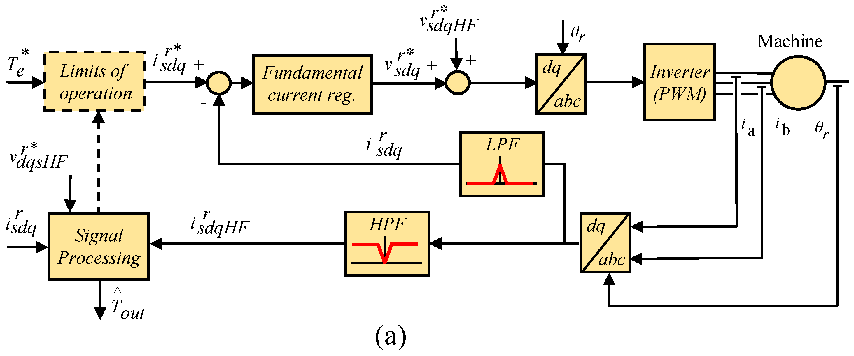
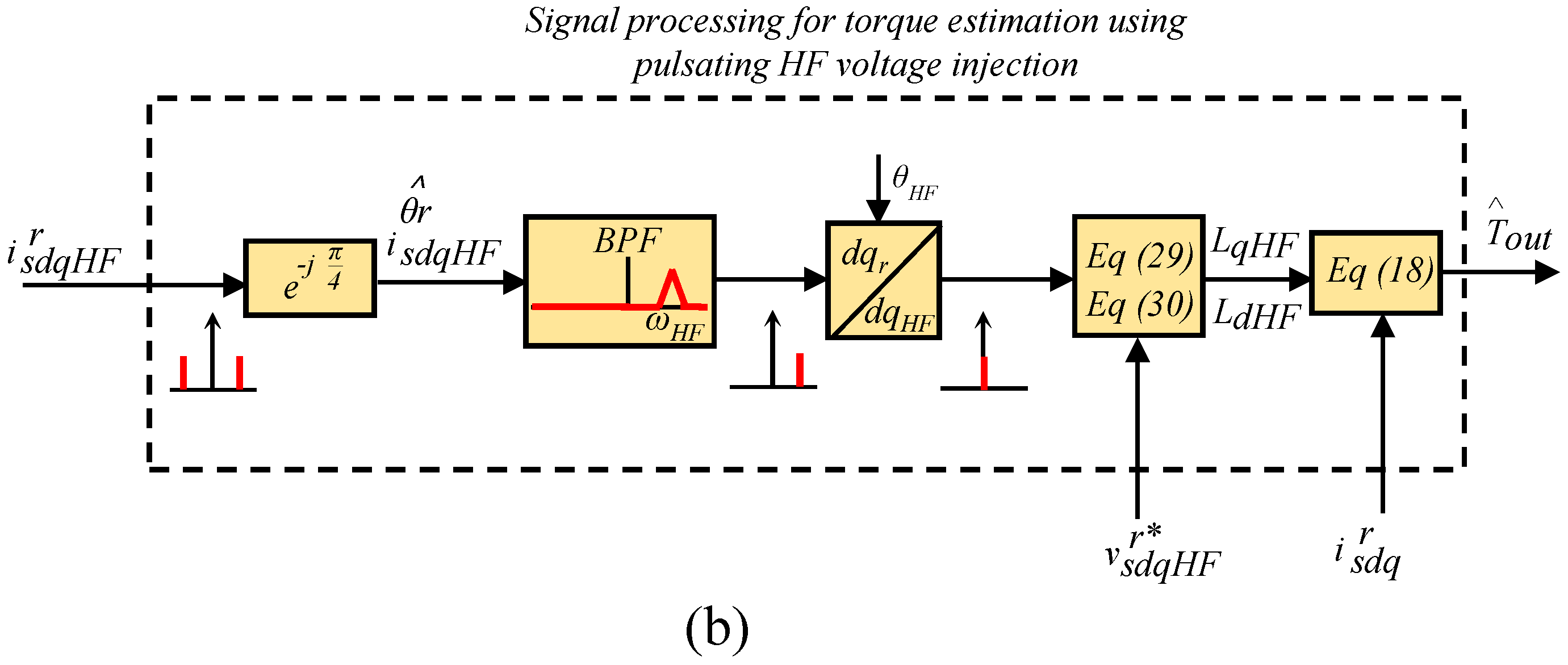
Figure 5 shows the inverter control block diagram and the signal processing needed for torque estimation when pulsating HF voltage injection at an arbitrary angle of injection,
, is used for
-axes HF inductance estimation. The HF voltage
, is injected in open-loop. A High-Pass Filter (HPF) is needed to isolate the HF components of the overall stator currents. Inputs to the signal processing block are the commanded HF voltage
, the induced HF currents
and the fundamental commanded current
. A Band Pass Filter (BPF) is used to isolate the positive sequence component of the HF induced current. The
d and
q-axis HF inductances are estimated using (
29) and (
30), the PM flux is estimated using (
17) and the output torque,
, is finally estimated using (
18). As the estimated
-axes inductances already reflect the effects of temperature on PM magnetisation state as well as the effects of fundamental current, knowledge of PM temperature is not needed.
Appealing properties of HF pulsating voltage injection are its simplicity and the fact that a single frequency allows the estimation of d- and q-axes HF inductances.
4.2. Rotating Voltage Injection
While the assumption of pure inductive behaviour at high frequencies can be acceptable for most PMSMs designs, it can be arguable for SynRMs. In this case, the use of a HF pulsating voltage at could incur in large errors in the estimated inductances, and consequently in the estimated torque. The use of a rotating HF voltage can be advantageous in this case.
When a rotating HF voltage (
31) is injected in a synchronous machine, the HF currents induced in stator windings can be obtained by inserting (
31) into (
8).
By solving (
8), the stator HF currents in the rotor synchronous reference frame are obtained as
It can be seen from (
32) and (
33) that obtaining
and
is not straightforward due to cross-coupling between
-axes. However, if the frequency of the injected HF signal is sufficiently higher than the rotor frequency, the rotor speed dependent terms can be safely neglected, the HF currents induced in the stator simplifying to (
34) and (
35). An orientative value for this assumption can be
rad/s [
12].
Estimation of
and
can be obtained from the imaginary part of the
-axes impedance (
36) and (
37).
Figure 6 shows the inverter control and signal processing for torque estimation using rotating HF voltage injection. As for the implementation shown in
Figure 5, the commanded HF voltage,
is injected in open-loop, with no additional controllers required. A High-Pass Filter (HPF) is also needed to isolate the HF components of the overall stator currents. Inputs of the signal processing block are the commanded HF voltage
, the induced HF currents
, and the fundamental commanded current
. The
d and
q-axis HF inductances are estimated using (
36) and (
37), the PM flux is estimated using (
17) and the output torque,
, is finally estimated using (
18).
The frequency of the HF signal should be sufficiently higher than the rotor frequency to safely neglect the rotor speed dependent (i.e., cross-coupling) terms. This can be problematic in the case of IPMSM designed to operate at very high-speeds. Furthermore, as the HF voltage is injected in a reference frame synchronous with the rotor, the effective frequency of the HF frequency signal will be . It must be guaranteed that it is smaller than half of the switching frequency (Nyquist frequency).
4.3. Pulsating Dq-Axes Current Injection
Injection of a pulsating HF current has been proposed as a viable mean to avoid issues due to the assumption of a purely inductive behaviour of the windings, as well as the problems with high speed machines discussed in the preceding subsections. HF inductances can be estimated by injecting two pulsating HF currents at different frequencies into the
d- and
q-axis. HF current controllers are needed for this purpose [
12]. The process to estimate
is described following, and identical procedure is used to obtain
.
If a HF current is injected into the
d-axis of the machine and the
q-axis current is force to be equal to zero (
38), the HF voltages commanded by the HF current controller will be of the form shown in (
39). A fictitious HF voltage vector can be defined consisting only of the
d-axis component
(
40). Both HF currents and voltages in (
38) and (
40) can be separated into positive sequence (
and
) and negative sequence (
and
) components, (
41) and (
42), of magnitude equal to half of the original signal. The
d-axis HF impedance (
43) can be obtained from the positive or negative sequence indistinctly. The
d-axis HF inductance is finally obtained as the imaginary part of (
43) and (
44).
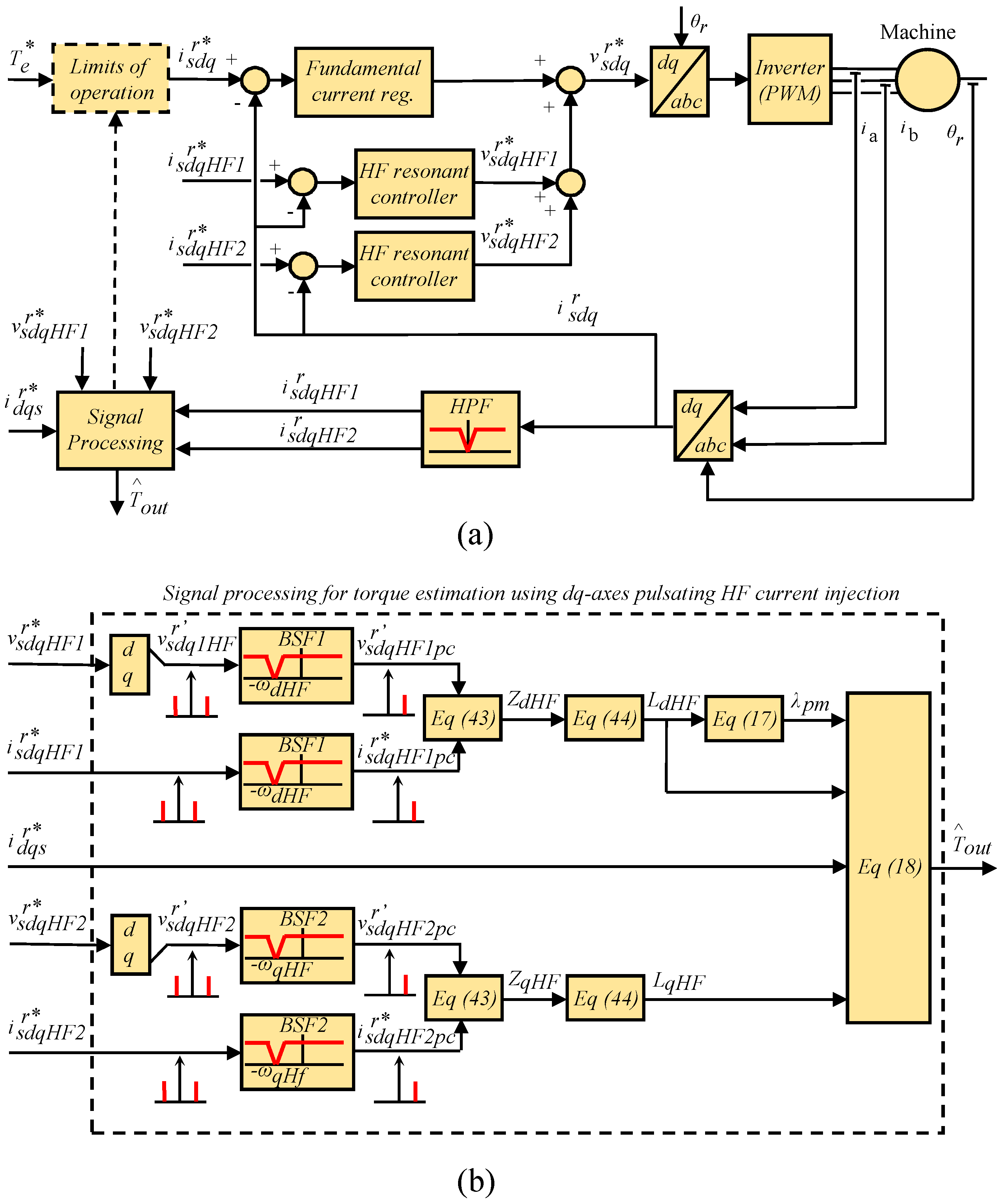
Figure 7 shows the inverter control block diagram and the signal processing needed for torque estimation when pulsating
-axes HF current signals are used for
-axes HF inductance estimation. Two HF resonant current controllers (
45) are used to inject the HF currents, where
is the proportional gain,
is the resonant frequency, and
c is the zero position of the controller.
Inputs to the signal processing block are the commanded high frequency resonant currents
and
, the output voltage of the resonant controllers
and
and the fundamental commanded current
. Two band stop filters,
and
, are used to remove the negative sequence components of the HF currents and voltages. The
d and
q-axis HF impedances are estimated using (
43), the
d and
q-axis HF inductances are estimated using (
44), the PM flux is estimated using (
17) and, the output torque,
, is finally estimated using (
18).
Note that in this case a pure inductive behaviour is not assumed, cross-coupling terms do not affect to the estimations either. However, the fact that there are two HF signals might have a larger impact on machine performance (noise, vibration, ...) compared to methods using a single HF signal, the computational burden also being larger. Finally,
Table 2 summarises the main characteristics of the methods analysed in this section.
6. Conclusions
Parameter estimation using HF signal injection aimed to improve the accuracy of torque estimation methods has been addressed in this paper, with the aim of making the estimation robust against variations in the operating conditions of the machine. This implies a reformulation of the torque equation, which will be function of the HF (incremental) inductances instead of the absolute inductances. Accurate modelling of the relationship between the incremental and absolute inductances will be therefore of paramount importance. Additionally, estimation of the PM flux is based on the linear relation with the d-axis inductance.
Three different types of HF signal injection have been considered: Pulsating Voltage Injection, Rotating Voltage Injection and Pulsating -axes Current Injection. In all the cases, the signal is superposed on top of the fundamental excitation applied by the inverter, not interfering therefore with the normal operation of the drive. It is concluded that pulsating current injection is advantageous as it is insensitive to the resistive components of the HF model and to cross-coupling effect. In change, its implementation is slightly more difficult due to the need of HF current controllers. In all the cases, no modification of the hardware is required.
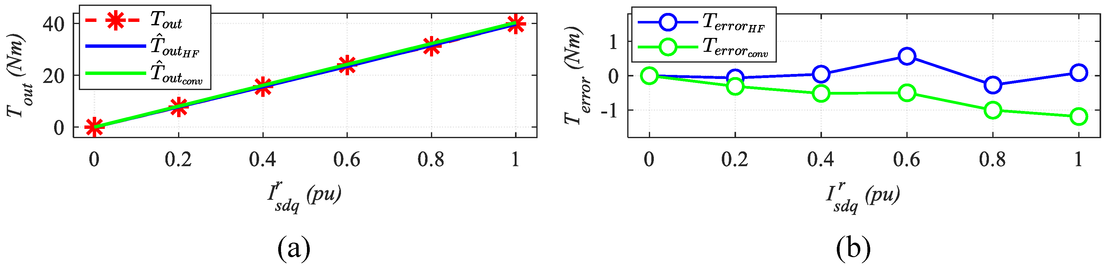
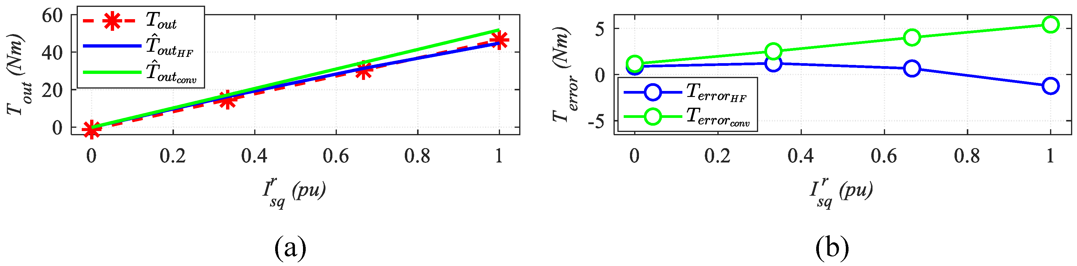
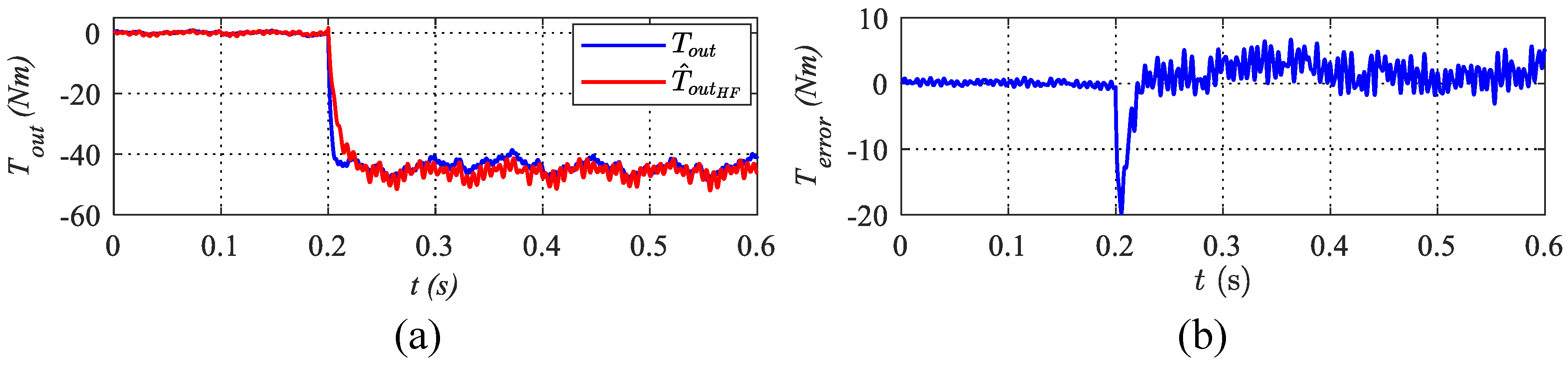
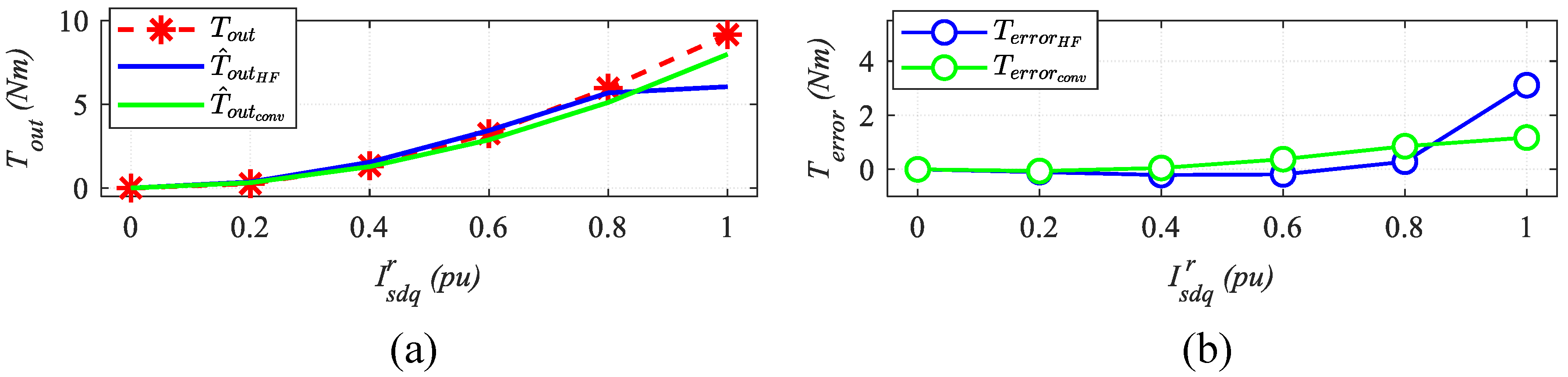
Experimental verification using IPMSM, a SPMSM and a SynRM have been presented, which confirm the viability of the proposed methods.


