1. Introduction
AC electric drives are used in a wide variety of industrial applications such as in compressors [
1], in electric vehicle propulsion systems [
2,
3] and in more electric aircraft (MEA) [
4], among others. Although three-phase systems dominate the AC drive market, multiphase solutions are gaining popularity [
5,
6,
7]. Multiphase systems are preferable for applications where high fault tolerance is required [
8], such as for MEA applications, where electromechanical actuators (EMA) for control surfaces, fuel pumps, landing gears, environmental control systems and starter-generators need to be operated [
9,
10,
11]. Apart from their intrinsic fault tolerance, other benefits of multiphase drives include a reduced current per phase (reducing copper losses and increasing efficiency) [
4], noise and electromagnetic interference (EMI) minimization [
12,
13], higher power density and lower torque ripple [
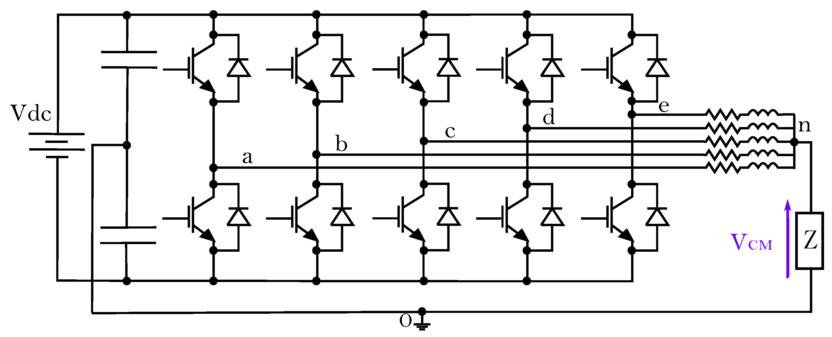
14], making them attractive for transport electrification. Among the multiphase topologies available in the scientific literature, star-connected five-phase technologies (
Figure 1) can be highlighted, as they provide a good trade-off between system complexity and fault tolerance [
15,
16]. Specifically, multiphase permanent magnet synchronous machines (PMSM) are being considered for aircrafts due to their superior power density [
17,
18].
In general, AC electric drives can experience issues due to the common-mode voltage (CMV) [
19] and common mode currents (CMC) [
20]. CMV variations are generated by the commutation of the power converter devices, producing EMI [
21] and bearing currents that can compromise the integrity of the electric machine [
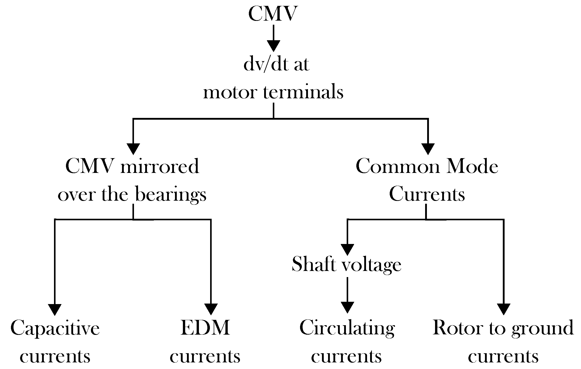
22]. Such voltage variations create new capacitive paths through the motor bearings, leading to premature aging. Capacitive currents, electrostatic discharge machine (EDM) currents, circulating currents and rotor-to-ground currents can flow through the bearings [
23,
24] (
Figure 2), and their harmful effects depend on the type of bearing, size of the machine and how the machine is used.
Operating at higher switching frequencies can entail more severe CMV related issues (additional EMI generation and larger number of
dv/dt) [
26]. As considerable efforts are being carried out to widespread the usage of wide bandgap (WBG) devices in AC drives, much higher switching frequencies are expected in the future, making the investigation on CMV mitigation a popular topic [
13,
19,
20]. Thus, a wide variety of solutions have been proposed in the literature. Such solutions can be classified as passive or active. Passive solutions are those which mitigate or eliminate the harmful effects generated by CMV, while active solutions are intended to reduce or totally avoid CMV generation. Among passive solutions, Faraday shielding [
27,
28], ceramic and hybrid bearings [
22,
29], shielded cables [
23,
30] and shaft grounding rings [
27,
31] can be highlighted. On the other hand, modulation techniques and new inverter topologies such as multilevel inverters [
32], single-phase transformerless inverters [
33,
34] and three-phase inverters [
35] among others [
36] are the most common active solutions. Among all these solutions, modulation algorithms can be considered for CMV reduction in star-connected five-phase AC drives due to their ease of implementation, low cost, and because no additional hardware is needed.
In [
37], the authors initially proposed a CMV reduction modulation technique for five-phase inverters, named AZSL5M5-PWM. However, the proposal has been only considered for passive loads (star-connected
loads) and solely validated in open-loop. From the obtained results, it has been concluded that the linear range of the original AZSL5M5-PWM is limited, which can prevent the utilization of this technique in electric drives where operation close to the base speed (without entering in field weakening region) is desirable, as is the case in most EMA systems. Thus, a hybrid AZSL5M5-PWM technique (HAZSL5M5-PWM) that provides the same linear range as conventional space vector PWM (SV-PWM) is proposed in this work, and its performance is evaluated in an EMA system.
This manuscript is organized as follows. First of all, conventional SV-PWM for star-connected five-phase power systems is presented, where the harmonic projection of the stator voltages into their corresponding orthogonal subspaces by means of Clarke transformation is mathematically justified. After that and considering the third harmonic elimination constraint, it is shown how CMV variations are generated in the multiphase drive. Secondly, the most relevant reduced common-mode voltage PWM (RCMV-PWM) modulation techniques are briefly described, focusing on their limitations. After that, the proposed Hybrid AZSL5M5-PWM modulation technique is presented providing the required tools for duty cycle calculation, and validated by means of simulation. The target of the proposed modulation technique is to effectively reduce CMV in star connected multiphase systems, while the hybridization is performed to cover the whole operation range of the drive. Open-loop and detailed five-phase EMA simulations are conducted to perform the validation, where not only CMV reduction is verified, but other figures such as total harmonic distortion (THD) and efficiency are evaluated in order to demonstrate that the achieved CMV reduction does not significantly penalize other relevant drive figures.
2. Influence of the SV-PWM Technique in the CMV of a Star-Connected Five-Phase AC Drive
SV-PWM is one of the most used modulation techniques in three-phase and multiphase power systems thanks to its easy digital implementation and optimum DC bus voltage utilization. As a star-connected five-phase system has four degrees of freedom, stator voltages and currents can be represented into two separated two-dimensional planes,
-
and
x-
y, and one homopolar component by means of the following amplitude invariant Clarke transformation [
38]:
The Clarke transformation allows us to decouple the 5-dimensional voltage vector in the
reference frame into three orthogonal subspaces (
-
,
x-
y and 0). For a surface-mounted permanent magnet synchronous machine (SM-PMSM), this decoupling is done through the diagonalization of the inductance matrix
(
2).
For SM-PMSMs, the elements of
can be considered invariant with respect to the rotor angular position, as the surface placed magnets have a permeability near that the one of the air. Therefore, a SM-PMSM behaves like a non-salient pole synchronous machine [
39]. As the windings in each phase are manufactured identically, the mutual inductances between any pair of phases separated with the same electrical angle are equal, i.e.,
(if
) or
(if
). Similarly, all the self-inductances are equal (
). This type of matrix is known as a circulant matrix, and it has some special properties [
40]. For example, it guarantees that
is orthogonally diagonalizable by a transformation represented by a
real matrix [
41,
42].
The circulant matrices are diagonalized by the Fourier Matrix [
40,
43]. Therefore, the Clarke transformation decomposes the 5-dimensional vectors according to their harmonic components. In the
-
sub-space, the
harmonic components are projected while, in the
x-
y sub-space, the
ones are projected, being
[
41,
44]. The harmonic components of order
are projected into the zero-sequence or homopolar sub-space. In
Table 1, the odd harmonics associated with each sub-space according to the Clarke transformation of (
1) are presented for a 5-phase machine.
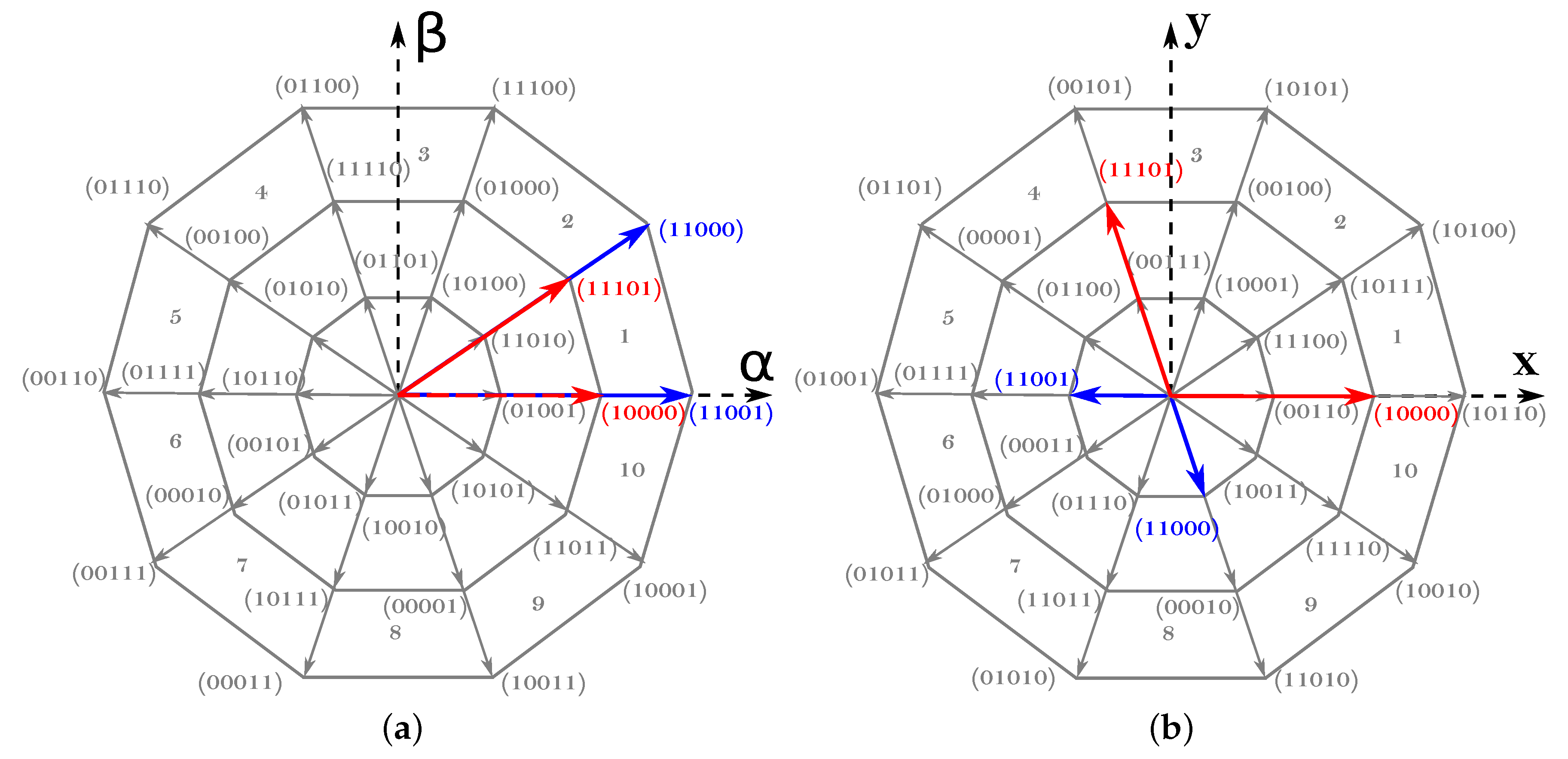
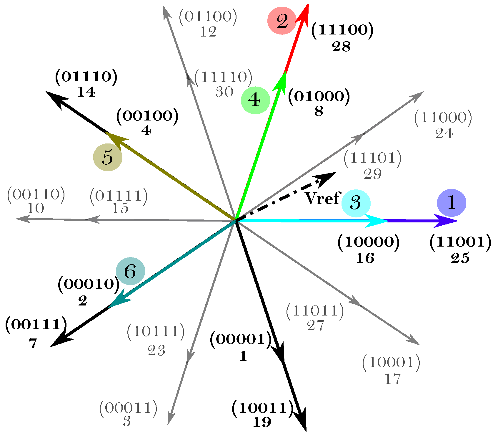
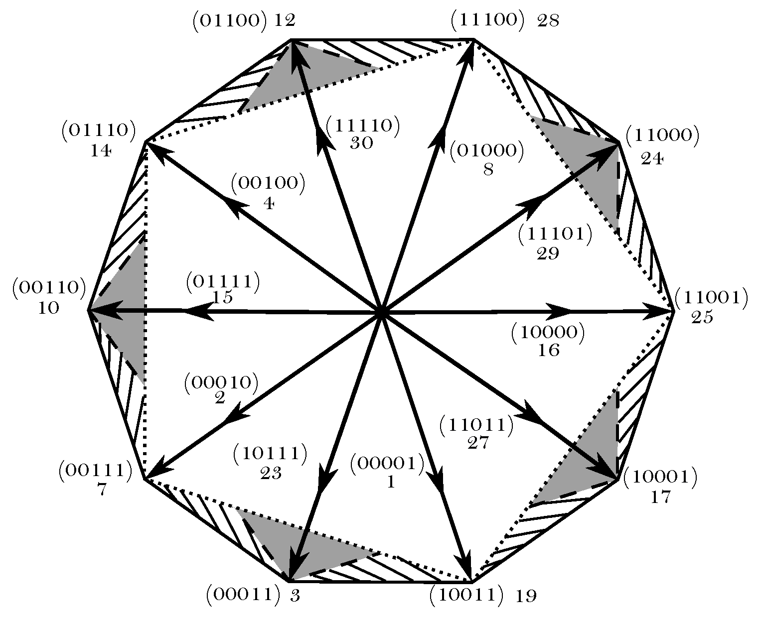
The number of possible switching states or space vectors is
, where 30 are active vectors and two are zero vectors (
Figure 3). Active vectors can be classified depending on their magnitude as:
Large vectors, where
, which correspond to the outer decagon of
Figure 3.
Medium vectors, where
, which correspond to the middle decagon of
Figure 3.
Small vectors, where
, which correspond to the inner decagon of
Figure 3.
For an
n-phase system,
active vectors must be applied at each commutation period in order to achieve a sinusoidal output [
45]. Thus, four active vectors must be used in a star-connected five-phase system. Although various possible active vector combinations are possible to produce a given output voltage vector, the most common alternative consists on using two large and two medium adjacent vectors. As an illustrative example,
Figure 3 shows the vectors used to synthesize a given reference voltage vector located in the first sector of the
-
plane, being the following the application sequence that minimizes switching losses: 00000, 10000, 11000, 11001, 11101, 11111, 11101, 11001, 11000, 10000, 00000. If the third harmonic component needs to be eliminated, the application-time ratio between medium and large vectors must satisfy (
3), as with this ratio the sum of the applied vectors in the
x-
y plane is zero (
Figure 3) [
46].
As a result, the maximum achievable output voltage following this modulation approach is:
and the CMV generated in the five-phase system is:
When using SV-PWM and applying the vector sequence that corresponds to the first sector of the
-
plane, the CMV waveform of
Figure 4 is obtained. From (
5), it can be deduced that all large and short vectors generate CMV levels of
, while CMV levels are of
for medium vectors and of
for null vectors. When evaluating the impact of the CMV, the difference between the maximum and minimum CMV levels (
,
Figure 4) must be considered, and the number of CMV variations for each commutation period (
) must also be taken into account.
3. RCMV-PWM Techniques
As zero vectors are responsible for generating the maximum CMV levels (
Figure 4), most of the RCMV-PWM techniques avoid the application of these vectors to reduce
and
. In [
38], an extension of the three-phase active zero state PWM (AZS-PWM) [
47] modulation technique to the five-phase scenario is proposed. This technique replaces zero vectors by applying two active vectors with the opposite phase at the same time. In this work, this technique will be named AZSL2M2-PWM as, apart from the active vectors that substitute zero vectors, two large (L2) and two medium (M2) vectors are used at each modulation period. This technique shows a good harmonic performance and DC bus utilization, being its linear range
. However,
is not greatly reduced, as only
CMV levels are avoided (
Table 2). Similarly, a modulation algorithm that employs four large active vectors in conjunction with two active vectors with opposite phases (AZSL4-PWM) is proposed in [
38]. This technique has the same linear range as SV-PWM and AZSL2M2-PWM, and considerably reduces
, as only applies large vectors. Nonetheless,
remains as for SV-PWM (
Table 2).
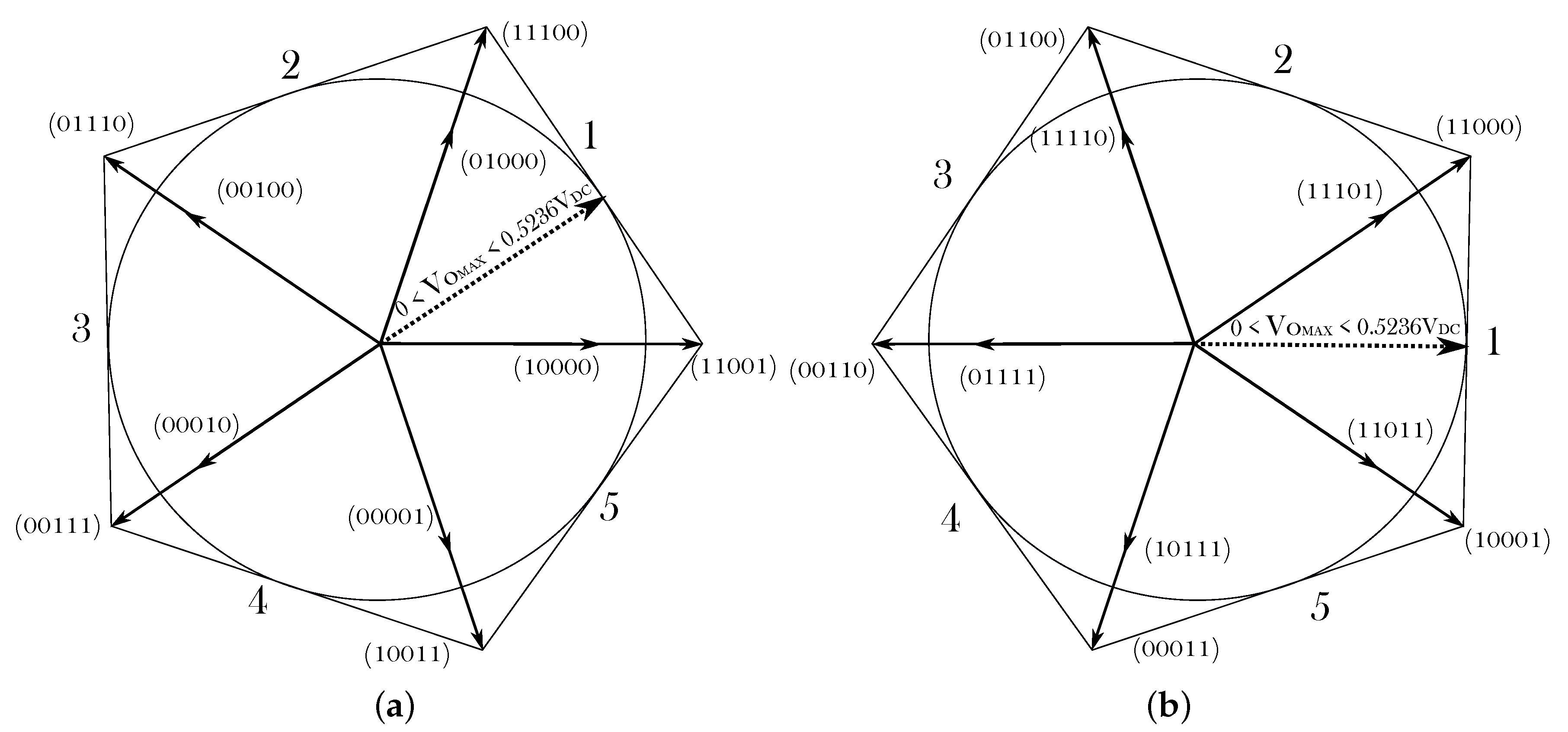
M5-PWM [
48] and L5-PWM [
49] techniques completely eliminate
and
by only using odd or even medium (M5-PWM), or odd or even large (L5-PWM) active vectors. However, this is achieved at the cost of introducing additional power losses, significantly reducing the linear range up to 0.5257 for M5-PWM (
Table 2), and generating high harmonic distortion for L5-PWM, making them inappropriate for many industrial applications. Authors in [
48,
49] also propose variants that use ten medium (M10-PWM) or ten large (L10-PWM) vectors. These techniques enhance the linear range by increasing the available vectors, but do not reduce
and
as much as with M5-PWM and L5-PWM (
Table 2).
Among the reviewed techniques, AZSL2M2-PWM and L10-PWM best suit for industrial applications, as they keep the linear range with a reasonable THD while effectively reducing . However, reduction by means of such modulation algorithms is limited. Thus, a new RCMV-PWM technique that further reduces while keeping an extended linear range is proposed in the following section.
5. Simulation Results
In order to validate the proposal, two simulation platforms have been implemented in Matlab/Simulink. On the one hand, an open-loop model has been created to evaluate the HAZSL5M5-PWM technique and compare its performance with other existing ones regardless of the influence of a control algorithm. On the other, a detailed five-phase EMA model has been implemented to evaluate the proposal in the context of a variable speed AC drive. Without losing generality and in order not to significantly increase the computational burden of the model, ideal switch models that do not consider switching transients nor dead-time effects have been adopted in both simulation platforms. The obtained results and their discussion are provided in the following.
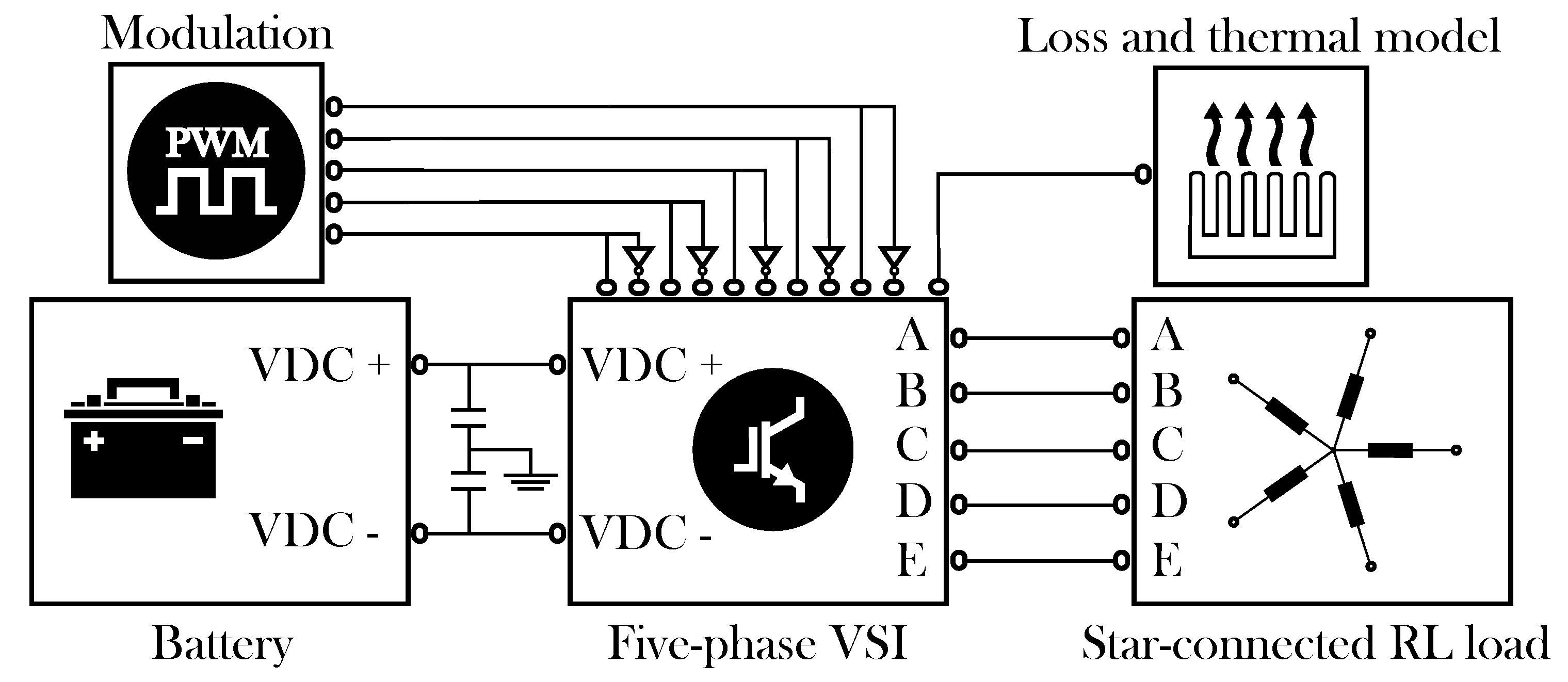
5.1. Open-Loop Model Simulation Results
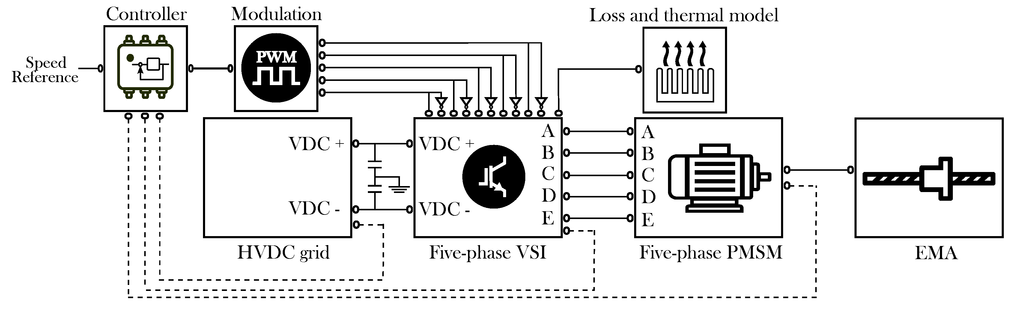
Figure 8 shows the open-loop model block diagram. SimPowerSystem blocks have been used to model the power elements. The battery has been modeled as an ideal DC voltage source. The power-converter block includes a two-level five-phase voltage source inverter, where each switching device includes a detailed loss and thermal model, allowing an accurate estimation of inverter losses. In this work, a loss model of the International Rectifier AUIRGPS4067D1 IGBT has been implemented for each switch, whose main parameters are detailed in
Table 5. The loss and thermal model follows the same approach as the one presented by the authors in [
50]. The analytical approach used in this work to estimate the instantaneous conduction and switching losses is commonly used by the scientific community [
51] and by the industry [
52]. On the other hand, the adopted 1D thermal modeling approach has been verified by the authors in [
53], where it has been compared to 3D finite element method (FEM) simulation, obtaining almost the same results. Finally, a passive star-connected five-phase RL load has been included. The most significant parameters of the open-loop model are collected in
Table 6.
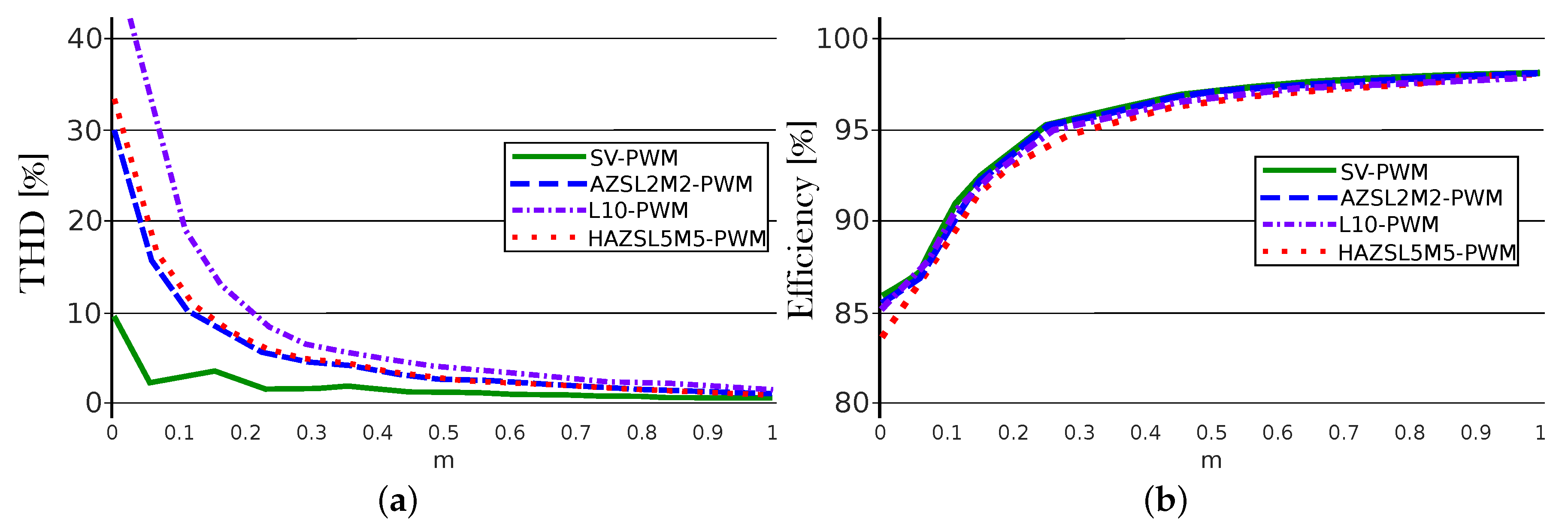
Figure 9 shows the THD and the efficiencies obtained for the proposed algorithm and for other techniques for all the linear range. As it was expected, RCMV-PWM modulations show greater harmonic content when compared to SV-PWM due to the use of phase-opposite vectors. However, for high modulation index values, all the studied modulations produce a similar THD. On the other hand, while AZSL2M2-PWM and SV-PWM have similar efficiencies, the HAZSL5M5-PWM has a slightly lower efficiency, which increases for low modulation indexes.
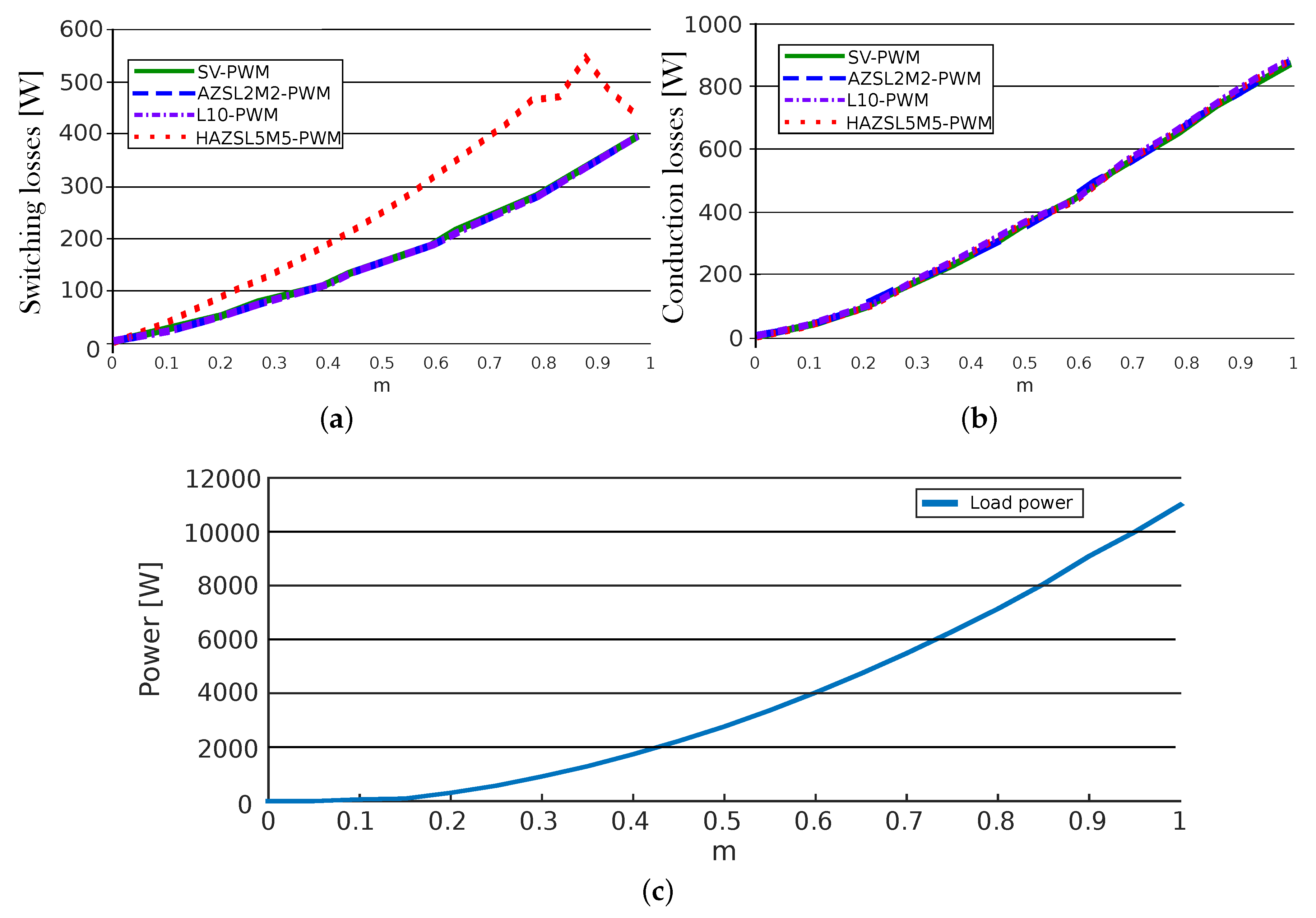
Power losses can be seen in more detail in
Figure 10. As mentioned before, HAZSL5M5-PWM requires more commutations at each vector change which entails an increase of switching losses (
Figure 10a). However, conduction losses are almost equal in all modulations (
Figure 10b). On the other hand,
Figure 10c shows the load power as a function of the modulation index.
Regarding CMV mitigation, the proposed HAZSL5M5-PWM technique reduces and by a 60% and 80%, respectively, when . These percentages are reduced while m gets close to 1. The worst case scenario, when modulation index is 1, AZSL5M5-PWM is active 29.78% of the simulated time while SV-PWM is active the 70.22% of the simulated time. In such a case, the is reduced by 17.86% and is reduced by 23.82%. In addition, when applying the operation condition equivalent to maximum torque ( = 26 Nm) and maximum speed ( = 105 rpm) that allows this particular application (modulation index = 0.96), AZSL5M5-PWM is active 49.8% of the simulated time while SV-PWM is active the 50.2% of the simulated time, reducing the by 29.88% and by 39.84%. So, even when the most torque and speed values are considered, HAZSL5M5-PWM reduces the as much as AZSL2M2-PWM and L10-PWM techniques.
5.2. EMA Model Simulation Results
Figure 11 shows the block diagram of the implemented EMA model where, as in the open-loop model, the same power loss model based on the International Rectifier AUIRGPS4067D1 IGBT has been implemented. The EMA incorporates a star-connected five-phase PMSM, which third harmonic back-EMF component is negligible.
Table 7 shows the main parameters of the simulated EMA.
The five-phase PMSM stator voltages are given by:
where
and
are five-dimensional vectors whose element (
and
,
) are the per-phase voltages and currents, respectively.
is a
diagonal matrix, where each diagonal element represents the phase resistance.
is the
stator inductance matrix, where each element
(
) represent the self- (
) and mutual-inductances (
) between phases
i and
j. Being the value of the mutual-inductances very low and magnetic saturation phenomena negligible, mutual-inductances have been considered zero and self-inductances have been considered constant in the implemented electric machine model. A perfectly balanced stator has been considered. These assumptions have been done without losing generality for the evaluation of the proposed modulation algorithm as, if any non-ideality is present in the electric drive, torque and speed loops are responsible of their compensation, while the proposed algorithm synthesizes the commanded reference voltages and minimizes CMV. The term
is the five-dimensional flux linkage vector (
) produced due to the permanent magnets.
The torque produced by the motor is given by:
where
is the angular mechanical rotor position. The dynamics of the rotational movement are given by:
where
is the load torque produced by the EMA,
J is the total inertia moment of the rotating masses, including EMA and motor,
is the rotational speed of the rotor and
B is the viscous friction coefficient.
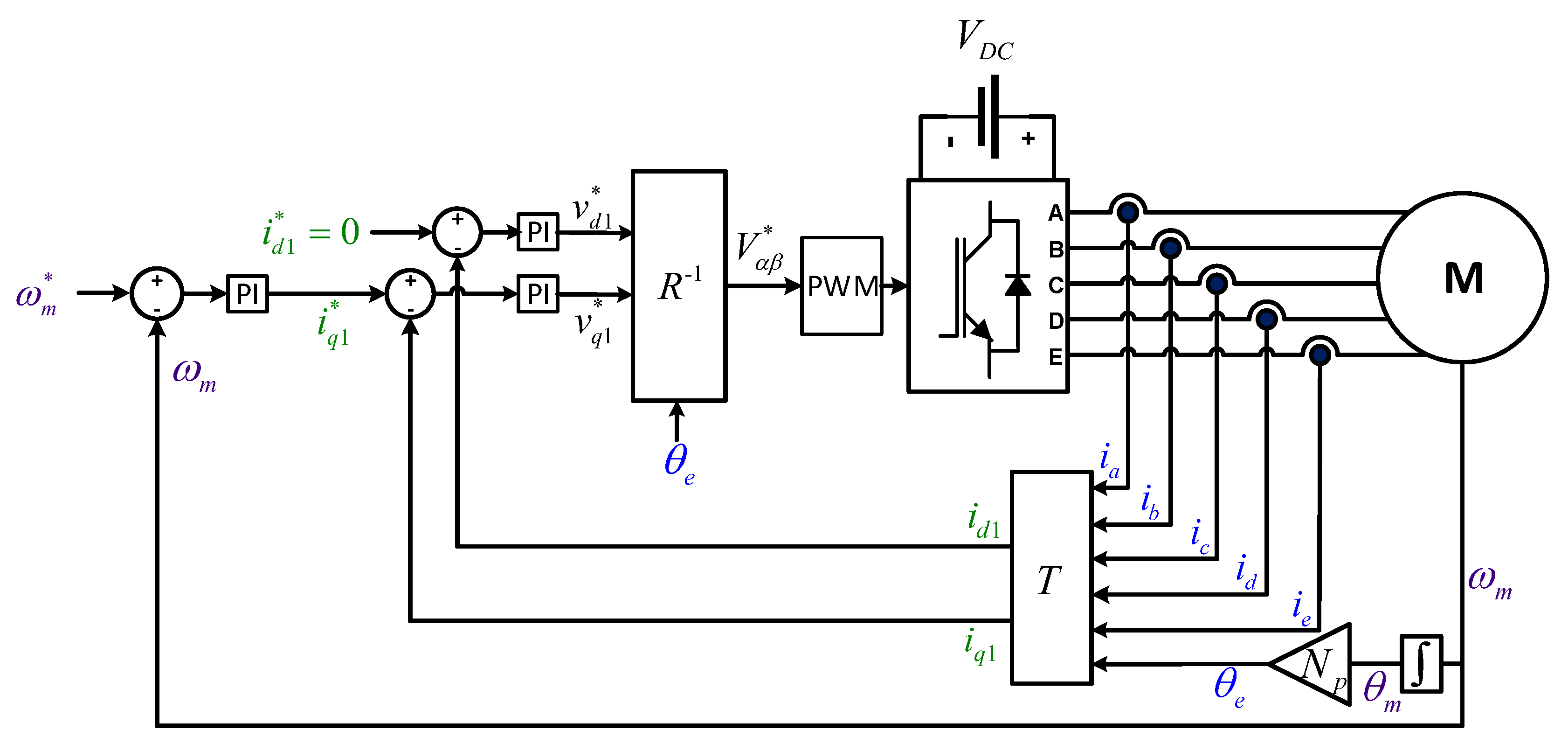
Figure 12 shows the detailed diagram of the controller. The controller consists of two control loops. The outer one regulates the rotational speed of the motor. This loop has a proportional-integral (PI) controller tuned in
z. For this application, the damping factor has been set to
, while the settling-time has been set to
ms. The inner loop tracks the current references through a vector controller [
54]. Again,
for the current regulator, while
ms. In this particular case, only two PI controllers are required to control the first harmonic components (
), as there is no third harmonic back-EMF component and the proposed PWM technique intrinsically regulates to zero the third harmonic voltages (
and
are imposed to be zero). It must be taken into account that, for this particular control approach, a conventional microcontroller sine-triangle PWM peripheral cannot be used due to the modulation algorithm computational requirements. Thus, an FPGA should be incorporated to implement the modulation algorithm, while implementing the speed and current loops in a fixed-point or floating point DSP.
Therefore, the following
to
-
transformation (
T) is used in the controller:
this being the matrix product of the transformation in (
1) with the following rotational matrix:
where
is the electrical rotor position of the motor, being
.
Once the inner loop PI controllers provide the voltage references (
), such references are transformed into the
frame by applying the
(pseudo-inverse of
R) matrix and fed to the PWM block. Matrix
is the classical counter-clockwise rotation transformation [
42]:
Several simulations have been performed for various torque and speed conditions that cover the whole operation range of the EMA in order to evaluate the figures of the HAZSL5M5-PWM algorithm compared to other techniques.
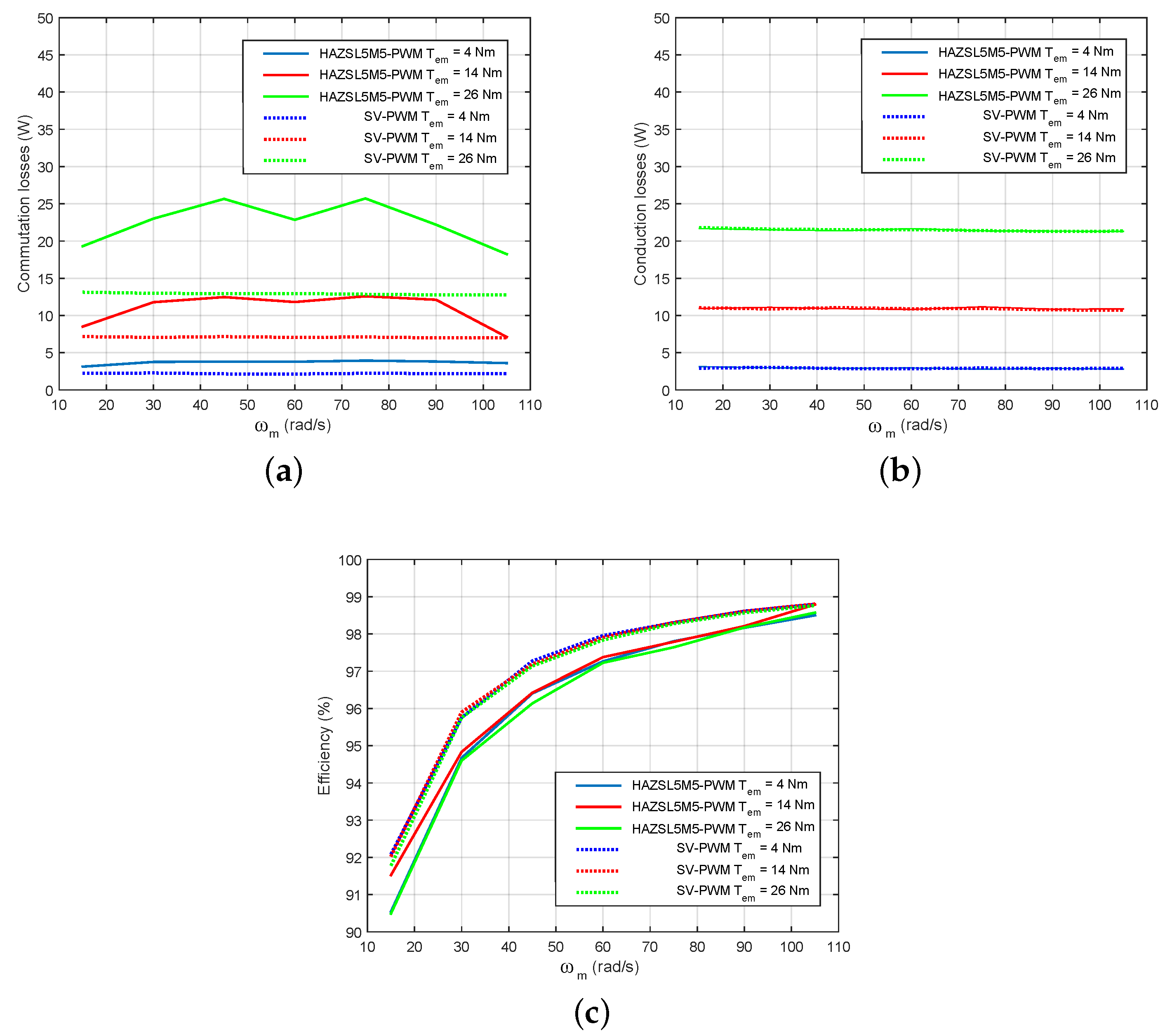
Figure 13a–c show the efficiency results and the distribution between conduction and switching losses. Similar results as in open-loop simulations have been obtained for the EMA platform. As expected, switching losses increase when applying HAZSL5M5-PWM. However, such losses are not linear since hybrid AZSL5M5-PWM also includes SV-PWM algorithm and, when high modulation indexes are required, SV-PWM and HAZSL5M5-PWM techniques operate together reducing commutation losses. In terms of overall system efficiency, it is only reduced for about 1% when compared HAZSL5M5-PWM to SV-PWM. However,
and
are significantly reduced thanks to the proposed technique. In addition, in this particular application, AZSL5M5-PWM is operating all the time in all the simulated operation points except the one described in the previous section (
= 26 Nm and
= 105 rpm). Consequently, the benefits of the AZSL5M5-PWM are fully exploited in the vast majority of the operation points of this application.

 ,
, 


