Abstract
A ground source heat pump system is one of the high-efficient technologies for space heating and cooling since it uses stable underground temperature. However, in actual application, many situations cannot be achieved due to the unsuitable design of operation. In particular, the design characteristics of buildings with different building load patterns are not reflected by the conventional design method. Moreover, the design capacity of the heat pump can be reduced by designing less capacity than the peak load through the introduction of the heat storage tank, but there is no related quantitative design method. Therefore, in this study, the effect of the ground source heat pump system design factors such as shape, length of the ground heat exchanger, and the capacity of the heat storage tank on the system performance was analyzed. To quantify the effect of such factors on system performance, an experimental plant was constructed and case studies were conducted for each design factor.
1. Introduction
In the 2015 Paris climate agreement, countries presented their goal for reducing greenhouse gases. To reduce greenhouse gas in the building sector, the concept of the zero energy building (ZEB) is being introduced. In particular, the government of South Korea made the ZEB roadmap. The main contents of the ZEB roadmap were to announce ways to activate ZEB in 2014 and to implement the ZEB certification system in 2017. Additionally, it is mandatory to build zero energy buildings in the public sector from 2020 and to build zero energy buildings in all buildings from 2025 [1]. To realize ZEBs, it is essential to introduce the high-efficiency and eco-friendly active elements using renewable energy systems as well as passive elements of buildings.
Among the renewable energy sources, the ground source heat pump (GSHP) system uses the underground constant-temperature zone that maintains a constant temperature throughout the year as a heat source. Therefore, it can respond to the cooling/heating load of the building in a stable manner. The ground source heat pump systems can be worked stable during the whole of the year due to the ground temperature is constant. However, other renewable energy systems such as PV and PVT are systems directly affected by outdoor conditions, such as cloud cover, and the seasons [2]. In South Korea, when a GSHP system responding to the cooling/heating load and hot water load of a building is designed [3], the heat transfer rate of the ground is fixed at a constant value or the required length is calculated by inputting the load and effective thermal conductivity into the GSHP system design software after measuring the ground effective thermal conductivity through the thermal response test (TRT). After the required length is calculated, the depth and number of geothermal boreholes are determined by the empirical values derived from the designer’s experience. Therefore, GSHP systems are designed by uniform methods in many cases instead of being designed to meet specific conditions according to the building load pattern, the introduction of the heat storage tank (HST), and the ground heat exchanger (GHEX) type. The American Society of Heating, Refrigerating and Air-Conditioning Engineers (ASHRAE) [4] provides quantitative values for performance changes according to the operating, design, and load conditions for GSHP system design. It, however, does not provide quantitative values for newly developed systems, such as the shape of the ground heat exchanger and the introduction of the heat storage tank. To address this problem, various studies [5,6,7,8,9,10,11,12,13,14,15,16,17,18] have been conducted using experimental and numerical methods.
Pu et al. [5] investigated the effect of pipe diameter, connection configuration, and Reynolds number of the ground heat exchanger through numerical simulation. As a result, the heat transfer rate per unit area increased with the decrease in pipe diameter. Li et al. [6] performed a study on the operation characteristics of the GSHP using the horizontal spiral coil. In addition, the performance factor of the horizontal spiral coil GSHP system is examined through the numerical simulation. They found the proper design method using the simulation results. Luo et al. [7] estimated the coefficient of performance (COP) of GSHP and groundwater heat pump in Wuhan city. The estimated heat pump COP of GSHP and heat pump COP of the groundwater heat pump system are 3.47 and 3.64. Quaggiotto et al. [8] analyzed the heat exchanger rate of double U-tube type and coaxial type through numerical simulation. According to the simulation result, heat transfer rate of coaxial type has a higher 6.3% in heating than that of the double U-tube. Bae et al. [9] analyzed the ground effective thermal conductivity according to the types of the ground heat exchanger through TRT. As a result, The ground effective thermal conductivity of the inner rib type has a higher 13.2% than that of the high-density polyethylene (HDPE) type. Qi et al. [10] performed COP analysis according to the connection type of ground heat exchanger through numerical simulation. According to the result, the COP of the parallel type of ground heat exchanger is 4.8% higher than that of the series type.
Kim et al. [11] evaluated the vertical closed-loop ground source heat pump (VGSHP) system with heat storage tank in order to improve the system performance of a VGSHP. VGSHP system coupled with heat storage tank showed an energy-saving effect of about 2% for cooling and about 15% for heating compared to the VGSHP system without heat storage tank. Yu et al. [12] analyzed heat pump COP and system COP according to the capacity of heat storage tank. GSHP linked heat storage tank system has a higher 15% heat pump COP compare to the GSHP system.
Spitler et al. [13] analyzed the performance measurement method and the performance factor of the GSHP system in a university building in Stockholm, Sweden. As a result, the measured COP is more affected by the amount of heating and cooling provided than by the entering fluid temperature to the heat pumps. Additionally, they examined the measurement method and the GSHP system performance of the previous studies. Bae et al. [14] evaluated the performance of a deep depth ground heat exchanger over 300 m using numerical simulation. The length of 300 m ground heat exchanger has 173% higher heat transfer rate than the length of 150 m ground heat exchanger. Chen et al. [15] analyzed heat transfer rate per unit and ground heat exchanger depth through numerical simulation.
Hughes, D. [16] investigated the performance of GSHP systems installed in the UK. Additionally, using the gathered data, the effect of GSHP system performance according to performance factors was analyzed.
Performance analysis studies are actively conducted according to performance factors [5,6,7,8,9,10,11,12,13,14,15,16]. However, most of the studies [5,6,8,10,11,14] were conducted through numerical analysis. Most experimental studies have been conducted to verify the suitability of sites by real-scale experiments [17,18]. Numerical studies involve both assumptions and uncertainties to assess system performance. Therefore, some differences may occur with actual performance. In addition, there is little evidence on how much design factors affect system performance. This study is important, in that the performance analysis is conducted according to the design factors through an experiment under actual load. The purpose of this study is to quantitatively analyze the performance of the ground heat exchanger type, the capacity of the heat storage tank, and the length of the ground heat exchanger, and to analyze the effect of each design factor on the performance through real-scale experiments.
2. Materials and Methods
2.1. Purpose of Experiments
In this study, experiments under the actual load were performed to analyze the heat transfer rate, heat pump COP, and system COP of the GSHP system according to the design factors of the GSHP system, such as the shape and length of the ground heat exchanger and the capacity of the heat storage tank. In addition, the performance of the heat pump and the effect of each design factor on the performance were analyzed.
2.2. Experimental Setup
Real-scale experiments were performed for a load of a factory building located in Hoengseong, Gangwon-do, South Korea. The factory building is a steel-frame building with double clear windows. For the experiments, small and large-scale experimental setups were constructed (Figure 1). Figure 2 shows the small-scale experimental setup (Site A), which was performed in a space of 85 m2. In the same space, two 20.11 kW heat pump systems were installed. Each system consisted of a ground heat exchanger, heat pump, heat storage tank, fan coil unit, and a circulation pump. To compare performances according to the shape of the ground heat exchanger, a typical HDPE ground heat exchanger was installed in one system, and an inner rib ground heat exchanger was applied to the other. In this instance, two boreholes were installed for each type of ground heat exchanger and the spacing between the boreholes was 5 m. Both systems consist of heat pumps, heat storage tanks, fan coil units, and circulation pumps of the same specifications, except for ground heat exchanger. Figure 3 shows the large-scale experimental setup (Site B), performed in a space of 595 m2. Ten boreholes were installed for ground heat exchanger, and each borehole being 150 m length. Moreover, to compare performances according to the capacity of heat storage tank, a bypass was installed so that the heat pump could directly exchange heat with fan coil unit. Table 1 shows the specifications of the experimental setup.
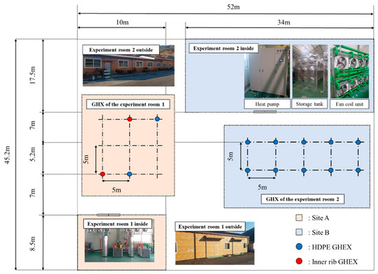
Figure 1.
Placement of ground source heat pump (GSHP) boreholes.
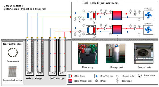
Figure 2.
Small-scale experimental setup (Site A).
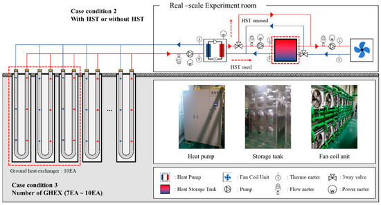
Figure 3.
Large-scale experimental setup (Site B).

Table 1.
Experimental conditions. HDPE: high-density polyethylene.
2.3. Experimental Method
The target building was assumed as a commercial building, and its operation started at 09:00 and ended at 18:00. Each experiment was performed for two days. For the small-scale system, case studies were conducted for each ground heat exchanger shape (typical and inner rib). For the large- scale system, case studies were conducted according to the capacity of heat storage tank, and ground heat exchanger length. Table 2 is the case conditions of the experiment. Case A1 and A2 compare the performance of the HDPE type and the inner rib type. Case B1~B3 compare the performance according to the capacity of heat storage tank. Case B1, B4, B5, and B6 compare the performance according to the length of the ground heat exchanger.
Table 2.
Case conditions. GHEX: ground heat exchanger, HST: heat storage tank.
2.3.1. Performance Comparison According to the GHEX Shape
To increase the heat transfer performance of the ground heat exchanger, previous studies have been conducted to change its shape or materials [5,6,7,8,9]. Most of the studies [5,6,7,8,9] on the shape of the ground heat exchanger, compared heat transfer performances through numerical simulation or experimentally analyzed the ground effective thermal conductivity through TRT. However, for the GSHP system applied to actual buildings, a steady state is maintained during a short period of time and the system is mostly operated under part-load condition. Bae [9] analyzed of heat transfer rate according to ground heat exchanger types. The types of the ground heat exchanger are HDPE type, inner rib type, the high-thermal-conductivity of pipe type, and coaxial type. Among the ground heat exchanger types, the inner rib type is shown the highest efficient thermal conductivity by TRT. Therefore, this study attempted to quantitatively analyze the performance under the actual load, for different shapes of heat exchanger using the same ground heat exchanger as that in the previous study. The small-scale experimental setup was used for the experiment that compared the performances of each ground heat exchanger shape. In the same space, heating was performed both, the inner rib ground heat exchanger and the typical ground heat exchanger for the experiment.
2.3.2. Performance Comparison According to the Introduction of HST
The introduction and capacity of heat storage tank to the GSHP system can reduce the capacity of the heat pump and improve the performance of the GSHP system [11,12,16]. Most studies [11,12], have quantitatively examined the performance change according to the introduction and capacity of heat storage tank using numerical simulation. Hughes et al. [16] have examined the performance change according to the introduction of heat storage tank through real-scale experiments. However, the studies compared systems installed at a different site. Therefore, in this study, experiments were performed considering different capacities of heat storage tank as case conditions to quantitatively analyze the performance of the GSHP system. The large-scale experimental setup was used to compare performances according to the capacity of the heat storage tank. When the heat storage tank is used, the heat pump performs heat exchange with heat storage tank, which in turn exchanges with fan coil unit. When the heat storage tank is not used, the heat pump on the load side performs heat exchange through the bypass path connected to the fan coil unit.
2.3.3. Performance Comparison According to the GHEX Length
The ground heat exchanger length is an important performance factor for the GSHP system, and most GSHP system design software is used to calculate the required length of ground heat exchanger. Most studies, however, have been conducted through the numerical analysis or the transient analysis of TRT [13,14,15,16]. Few studies [16] have examined the performance change according to the length of ground heat exchanger through real-scale experiments. However, the studies compared systems installed at a different site. The large-scale experimental setup was used to compare the performances of each ground heat exchanger length. In the experiment, the temperature of the 50 m3 heat storage tank was increased from 40 °C to 50 °C and the heat stored in heat storage tank was discharged through the fan coil unit. The ground heat exchanger length could be adjusted through the valve installed at each borehole. The length was varied from 1500 m to 1350 m, 1200 m, and 1050 m.
2.4. Measurement Method and Performance Calculation
To calculate the performance of the GSHP system, the temperature, flow rate of the circulating water, the heat pump power, and the circulation pump power was measured every minute. The measured data were recorded in a data logger. The ground heat transfer rate, heating capacity, and the COP were obtained using the measured data, and the uncertainties of the obtained values were calculated.
2.4.1. Performance Calculation Equation
The Equation (1) is based on heat transfer equation [10,19]. This equation can be used to calculate the heat transfer rate between ground heat exchanger and heat pump. Here, the heat transfer rate per meter can be calculated by dividing the ground heat transfer rate by the ground heat exchanger length as shown in Equation (2). The Equation (3) can be used to calculate the heating capacity of heat pump. The heating capacity represents the amount of heat transfer among the heat pump, heat storage tank, and fan coil unit. It can be represented by the sum of heat transfer rate and heat pump power [10]. The heat pump COP can be expressed as the ratio of the heating capacity to the required power [10,19].
Heat transfer rate between heat pump and ground:
Heat transfer rate between heat pump and ground per unit length:
Heating capacity:
Heat pump COP:
System COP:
where is the heat transfer rate between heat pump and ground [W]; is the specific heat of water [J/g·K]; is the flow rate of between heat pump and ground [g/s]; is the temperature of the circulating water from GHEX to heat pump [K]; is the temperature of the circulating water from heat pump to GHEX [K]; is the heat transfer rate per unit length [W/m]; is the length of the GHEX [m]; is the heat transfer rate between heat pump and load side [W]; is the flow rate of between heat pump and load side [g/s]; is the temperature of the circulating water from load side to heat pump [K]; is the temperature of the circulating water from heat pump to load side [K]; is the heat pump power [W]; is the coefficient of performance of the heat pump [-]; is the coefficient of performance of the system [-]; and is the circulation pump power [W].
2.4.2. Uncertainty Analysis
Table 3 shows the measurement errors of the measuring instruments used in the experiment. The uncertainty of the performance of the GSHP system was calculated using the method proposed by Talyor [20].
Table 3.
Measurement errors of the measuring equipment. COP: coefficient of performance.
The error of the temperature measuring instrument used in the experiment was ±0.2 °C, and the error rate of the instrument can be calculated using Equation (6). The error rate of the flow rate measurement was ±0.1% (Table 3). Here, the ground heat transfer rate and the heating capacity are determined by the temperature and flow rate. As the errors of the flow rate and temperature measurements are independent, the error rates of the ground heat transfer rate and the heating capacity can be expressed as shown in Equation (7). The heat pump COP can be expressed as the ratio of the heating capacity to the required power, and the uncertainties of the heating capacity and the heat pump power are independent. Therefore, the uncertainty of the heat pump COP can be expressed as shown in Equation (8). The measurement error of the heat transfer rate and COP calculated using Equations (6)–(8) was ± 4.0%.
Fractional uncertainty of the temperature:
Fractional uncertainty of the heat transfer rate:
Fractional uncertainty of the coefficient of performance:
where is the fractional uncertainty of the temperature [-]; is the absolute uncertainty of the temperature [K]; is the fractional uncertainty of the heat transfer rate [-]; is the fractional uncertainty of the flow rate [-]; is the fractional uncertainty of the coefficient of performance [-]; and is the fractional uncertainty of the power [-].
3. Result and Discussion
3.1. Performance Analysis According to the GHEX Shape
Figure 4 is a time-series graph showing the heat transfer rate of the HDPE ground heat exchanger. In the initial operation stage, heat transfer rate of HDPE is 15.8 kW, and at the end of the operation stage, heat transfer rate of HDPE is 10.0 kW. Figure 5 is a time-series graph showing the heat transfer rate of the inner rib ground heat exchanger. In the initial operation stage, heat transfer rate of the inner rib is 15.6 kW, and at the end of the operation stage, heat transfer rate of HDPE is 11.9 kW. Figure 6 is a time-series graph showing the heat pump COP of the HDPE ground heat exchanger. In the initial operation stage, heat pump COP of HDPE is 3.82, and at the end of the operation stage, heat pump COP is 2.59. Figure 7 is a time-series graph showing the heat pump COP of the inner rib ground heat exchanger. In the initial operation stage, heat pump COP of HDPE is 3.94, and in the end of the operation stage, heat pump COP is 2.83.
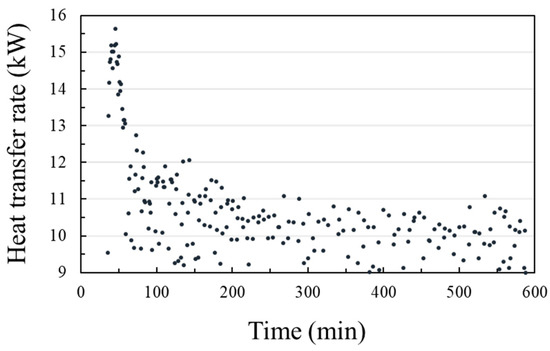
Figure 4.
Heat transfer rate—HDPE.
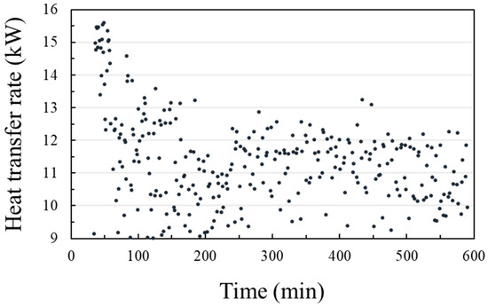
Figure 5.
Heat transfer rate—RIB.
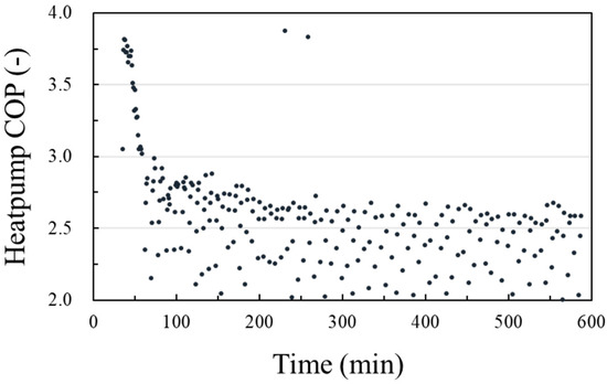
Figure 6.
Coefficient of performance—HDPE.
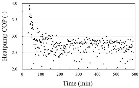
Figure 7.
Coefficient of performance—RIB.
Figure 8 show the average heat transfer rate, heat pump COP, and system COP according to ground heat exchanger types. The heat transfer rate, heat pump COP, and system COP of the inner rib are higher than those of HDPE. This is due to the influence of heat exchanger performance. The average heat transfer rate of the HDPE ground heat exchanger is 7.41 kW, and that of the inner rib heat exchanger is 7.95 kW. The average heat pump COP of the HDPE ground heat exchanger is 2.98, and that of the inner rib ground heat exchanger is 3.04. The power of the circulation pump is 6% higher for the inner rib ground heat exchanger than for the conventional HDPE ground heat exchanger. This is because the pressure drop is increased by the inner shape of the inner rib ground heat exchanger. However, the power of the circulation pump is 10% of the total power, and there is no significant effect on the system COP. The system COP of the HDPE ground heat exchanger is 1.94 and the inner rib is 1.97.
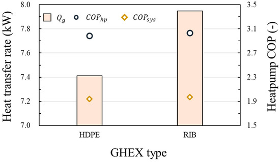
Figure 8.
Heat pump and system coefficient of performance (COP) and heat transfer rate according to the ground heat exchanger (GHEX) shape.
3.2. Performance Analysis According to the Introduction of HST
Figure 9 and Figure 10 are a time-series graph showing the entering water temperature (EWT) change and heat pump on/off schedule according to the use of heat storage tank. In the case without the heat storage tank, the heat pump was turned on and off frequently during the operation. In the case with the 20 m3 heat storage tank, heat pump was turned on and off twice during the operation. In the case with the 50 m3 heat storage tank, heat pump was turned on and off once.
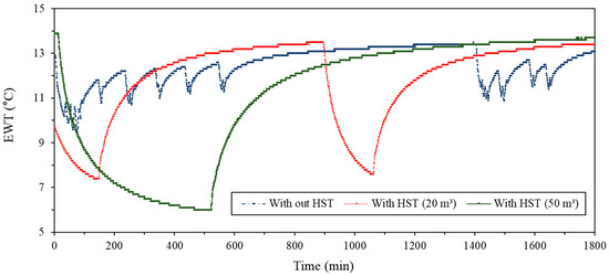
Figure 9.
Entering water temperature (EWT) change according to the capacity of HST.
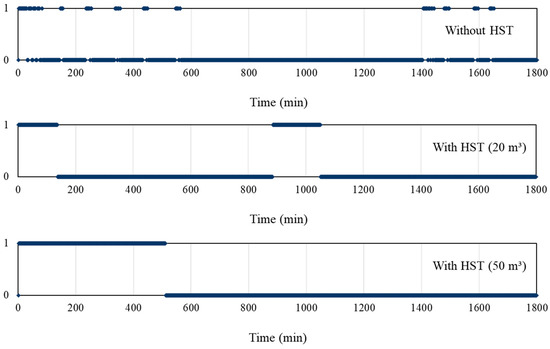
Figure 10.
Heat pump operation schedule according to the capacity of HST.
Figure 11 is a time-series graph showing the change of heat transfer rate according to the use of heat storage tank. In general, it takes time to reach the maximum heat transfer rate during the initial operation of the heat pump. In the case of not using heat storage tank, whenever a load is presented, the heat pump on and off repeatedly. Therefore, sections with a low heat transfer rate frequently occur at the time of initial operation. On the other hand, in the case of using heat storage tank, the on-off switching of the heat pump occurred up to two times. Therefore, the reduction of heat transfer rate according to the initial operation of heat pump has decreased. However, since the heat pump continues to operate to raise the temperature of the heat storage tank to 50 °C, the heat transfer rate is constantly reduced according to the decrease of the heat source side temperature and the increase of the load side temperature.
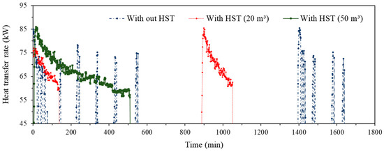
Figure 11.
Heat exchange rate (HER) change according to the capacity of HST.
Figure 12 is a time-series graph showing the heat pump COP change according to the capacity of heat storage tank. The heat pump COP showed a similar pattern to heat transfer rate. With the use of heat storage tank, the heat pump COP decreases due to the continuous rise in load side temperature. Therefore, in case of with 50 m3 heat storage tank, the heat pump COP decreases from 3.9 to 2.6. In case of without heat storage tank, the instantaneous maximum heat transfer rate is high. However, the COP is low before reaching the maximum value.
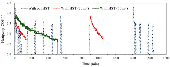
Figure 12.
Heat pump COP change according to the capacity of HST.
Figure 13 show the average heat transfer rate, heat pump COP, and system COP according to the capacity of heat storage tank. The average heat transfer rate in the case of without heat storage tank is 58.4 kW. The average heat transfer rates in the cases of 20 m3 and 50 m3 are 68.6 kW and 66.1 kW, respectively. The average heat pump COP and system COP in case of without heat storage tank are 2.96 and 2.32, respectively. The average heat pump COP and system COP in the case of 20 m3 heat storage tank are 3.18 and 2.33, respectively. The average heat pump COP and system COP in the case of 50 m3 heat storage tank are 3.12 and 2.29, respectively. The heat transfer rate and heat pump COP in case of using heat storage tank have higher than that of in case of not using heat storage tank. This is due to the influence of heat pump on-off frequency. However, the system COP of not using heat storage tank has higher than that of using 50 m3 heat storage tank. This is because of an increase in the system power due to the addition of a circulation pump when using the heat storage tank. The average heat transfer rate, the heat pump COP, and system COP in the case of 20 m3 heat storage tank have higher than those in the case of 50 m3 heat storage tank.
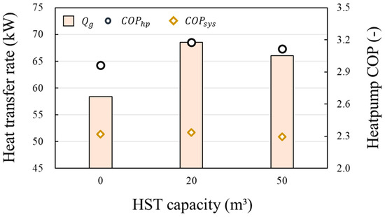
Figure 13.
Average values of the heat pump COP and heat transfer rate according to the capacity of HST.
3.3. Performance Comparison According to the GHEX Length
Figure 14a–d is a time-series graph showing the change of heat transfer rate according to the length of the ground heat exchanger. During the initial operation, all case of length is the similar value of heat transfer rate by 85~87 kW. However, the smaller the length of the ground heat exchanger, the more drastic the reduction of heat transfer rate over time. The heat transfer rate of 1050 m case is 52.5 kW at the end of the operation(Figure 14a), and that of the 1500 m case is 60.5 kW at the end of the operation (Figure 14d).
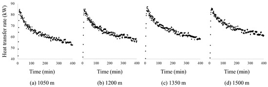
Figure 14.
Heat transfer rate change according to the GHEX length. (a) 1050 m; (b) 1200 m; (c) 1350 m; (d) 1500 m.
Figure 15a–d is a time-series graph showing the change of heat pump COP according to the length of the ground heat exchanger. The heat pump COP change is similar to the heat transfer rate. The heat pump COP of 1500 m case is 3.9 at the initial operation. However, the heat pump COP is decreased over time, and the value is 2.9 after operation for 400 min. The heat pump COP of 1050 m case is 2.6 after operation for 400 min.
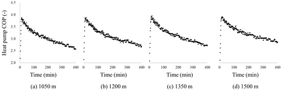
Figure 15.
Heat pump COP change according to the GHEX length. (a) 1050 m; (b) 1200 m; (c) 1350 m; (d) 1500 m.
Figure 16a shows the average heat transfer rate and heat transfer rate per meters of the ground heat exchanger according to the length of the ground heat exchanger. Here, the x-axis is the heat pump rated capacity divided by the ground heat exchanger length. The longer the length of the ground heat exchanger, the higher the heat transfer rate. In other words, the smaller the value of the ratio of heat pump rated capacity to ground heat exchanger length, the higher the heat transfer rate. The average heat transfer rate of 1050 m case is 61.1 kW, and that of the 1500 m case is 66.1 kW. However, the longer the length of the ground heat exchanger, the lower the heat transfer rate per meters of the ground heat exchanger (Figure 16b). The average heat exchanger rater per meters of 1050 m case is 58.2 W/m, and that of 1500 m case is 44.0 W/m. The heat transfer rate per meter, according to the ratio of the heat pump rated capacity to ground heat exchanger length can be expressed using a regression equation as shown in Equation (9).
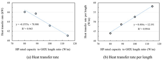
Figure 16.
Heat transfer rate change according to the GHEX length. (a) Heat transfer rate; (b) Heat transfer rate per length.
Figure 17 shows the average heat pump COP and system COP according to the ground heat exchanger. As the value of the x-axis increase, the heat pump COP and system COP decrease. In order words, the longer ground heat exchanger length, the higher heat pump COP, and system COP. The average heat pump COP of 1050 m case is 3.0. That of 1500 m case is 3.1. The average system COP of 1050 m case is 2.2. That of 1500 m case is 2.3. As the length of the ground heat exchanger increases by 450 m from 1050 m to 1500 m, the heat pump COP increases 5%, and the system COP increases 4%. The heat pump COP, according to the heat pump rated capacity to ground heat exchanger length ratio can be expressed using a regression equation, as shown in Equation (10).
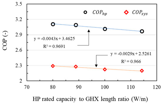
Figure 17.
Heat pump COP change according to the GHEX length.
The system COP, according to the heat pump rated capacity to ground heat exchanger length ratio can be expressed using a regression equation, as shown in Equation (11).
3.4. Effectiveness Analysis by Design Factor
Table 4 shows the results of heat transfer rate, heat pump COP, and system COP according to case studies. Figure 18a shows the effectiveness of heat transfer rate, heat pump COP, and system COP according to ground heat exchanger type. The result of heat transfer rate and COP analysis according to heat exchanger types showed that the inner rib ground heat exchanger is higher than the HDPE ground heat exchanger. In the case of using the inner rib ground heat exchanger, the heat transfer rate is increased by 7% compared to the HDPE ground heat exchanger, and heat pump COP and system COP are increased by 2%, respectively.
Table 4.
Result of GSHP performance according to design factor.
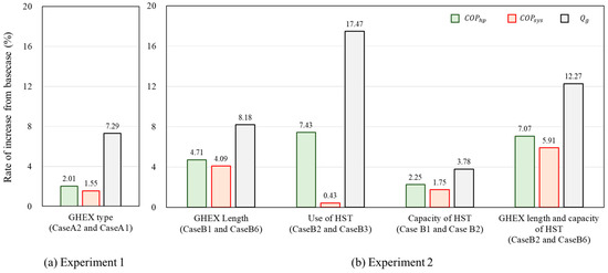
Figure 18.
Rate of increase according to performance factor. (a) Experiment 1; (b) Experiment 2.
Figure 18b shows the effectiveness of heat exchanger, heat pump COP, and system COP according to the capacity of heat storage tank and ground heat exchanger length. The result of heat transfer rate and COP analysis according to the capacity of heat storage tank showed that the case of using the 20 m3 heat storage tank is higher than the case of using 50 m3 heat storage tank and the case of do not use heat storage tank. In the case of with 20 m3 heat storage tank, the heat transfer rate, heat pump COP, and system COP are increased by 4%, 2%, and 2% respectively compared to the using 50 m3 heat storage tank. Using the 20 m3 heat storage tank, heat storage rate is increased by 17%, heat pump COP by 7%, and system COP by 0.4% compared to the case without the heat storage tank. As the length of the ground heat exchanger was reduced from 1050 m to 1500 m, the heat transfer rate increased by 8%, the heat pump COP by 5%, and the system COP by 4%. In case of with 20 m3 heat storage tank and ground heat exchanger length is 1500 m, the heat transfer rate increased by 12%, heat pump COP by 7%, and the system COP by 6% compared to the case of with 50 m³ heat storage tank, and ground heat exchanger length is 1050 m.
3.5. Compare to Previous Research
In the previous studies, performance analysis of various performance factors of the GSHP system was performed. [5,6,7,8,9,10,11,12,13,14,15,16]. However, most previous studies analyze the effectiveness of the design factor through numerical simulation [5,6,8,10,11,14]. The purpose of most experimental studies is to examine the suitability of the experiment site [17,18]. In particular, ASHRAE presented the design guideline for the GSHP system through experimental studies [4]. However, it is not considering the ground heat exchanger type and ground source heat pump linked heat storage tank system.
Some previous studies [5,6,7,8] analyzed performance according to the ground heat exchanger through numerical simulation. Few studies performed the experiment in the transient state through TRT. In order words, it is not performed COP analysis and response to the actual load. Bae et al. [9] analyzed ground thermal effective conductivity of HDPE type and inner rib type. As a result, the inner rib type has 13% higher heat transfer rate than the HDPE type under the transient state. In a steady state, the heat transfer rate of ground heat exchanger per meter can be calculated using Equation (12) [21].
In this study, the inner rib type has 7% higher heat transfer rate than the HDPE type under the actual load. This difference is due to the experimental environment. Under the actual load condition, the performance increase according to the ground heat exchanger type is small compared to the steady-state.
The performance analysis according to the capacity of heat storage tank was performed through the numerical simulation [11,12]. Kim et al. [11] analyzed energy according to use of heat storage tank. As a result, the GSHP linked heat storage tank system has saved energy 15% than the GSHP system. Yu et al. [12] analyzed heat pump COP and system COP according to the capacity of heat storage tank. GSHP linked heat storage tank system has a higher 15% heat pump COP compare to the GSHP system. In this study, the heat pump COP increase rate is 17% according to the introduction of heat storage tank.
Chen et al. [15] analyzed heat transfer rate per unit ground heat exchanger depth through numerical simulation. They found the regression equation of heat exchanger rate per unit depth according to the depth of the ground heat exchanger. As the depth of the ground heat exchanger increases by 1 m, the heat exchanger rate per unit depth decreases by 0.153 W/m. According to the results of this study, as the length of the ground heat exchanger increases by 1 m, the heat exchanger rate per unit length decreases by 0.031 W/m. This difference is due to the experimental environment and ground characteristics according to ground depth.
4. Conclusions
In this study, the performance analysis according to GSHP system design factors such as the ground heat exchanger type, capacity of heat storage tank, and ground heat exchanger length are performed in order to analyze the effect of performance factors. The experiment results were as follows.
- From the performance analysis, according to the ground heat exchanger, the heat transfer rate, heat pump COP, and system COP of the conventional ground heat exchanger were 7.41 kW, 2.98, and 1.94, respectively. Those of the inner rib ground heat exchanger was 7.95 kW, 3.04, and 1.97, respectively.
- As the result of performance analysis according to the capacity of heat storage tank, the heat transfer rate, heat pump COP, and system COP of 50 m3 heat storage tank were 66.1 kW, 3.11, and 2.29, respectively. Those of the 20 m3 heat storage tank were 68.6 kW, 2.33, and 3.18, respectively. When the heat storage tank was not used, the heat exchanger rate was 58.4 kW, heat pump COP was 2.96, and the system COP was 2.32.
- The longer the length of the ground heat exchanger, the higher the heat transfer rate. If the length of the ground heat exchanger is between 1050 and 1500 m, the heat transfer rate decreases by 0.153 kW per unit of the ratio of heat pump rated capacity to ground heat exchanger length. However, the heat transfer rate per unit length increases. The heat pump COP decrease by 0.0043 per unit of the ratio of heat pump rated capacity to ground heat exchanger length. The system COP decrease by 0.0029 per unit ratio.
- When the ground heat exchanger type, length, and storage tank capacity were adjusted within the designable range, the most important factor affecting heat transfer rate and heat pump COP was heat storage capacity. According to the heat storage capacity, heat exchanger rate increased 17% and heat pump COP increased 7%. The most important factor affecting the system COP was the ground heat exchanger length. As the length of the ground heat exchanger increased from 1050 to 1500 m, the system COP increased by 4%.
The GSHP system has a difference between short-term performance and long-term performance due to the change of ground temperature during long-term operation. This study does not consider the long-term performance of geothermal systems because it analyzes short-term performance according to GSHP system design factors. In the future, the effect of performance factors will be analyzed from a long-term perspective, and a manual for the efficient design of the GSHP system will be prepared.
Author Contributions
Methodology, H.K. and Y.N.; Investigation, H.K. and S.B.; Data curation, H.K.; Writing—Original Draft Preparation, H.K. and Y.N.; Writing—Review and Editing, H.K. and Y.N.; Supervision, Y.N. and J.S.C.; Experiment equipment construction, J.S.C. and S.B.K. All authors have read and agreed to the published version of the manuscript.
Funding
This work was supported by the Korea Institute of Energy Technology Evaluation and Planning (KETEP) and the Ministry of Trade, Industry & Energy (MOTIE) of the Republic of Korea (No. 20163030111350) and this research was supported by Basic Science Research Program through the National Research Foundation of Korea (NRF) funded by the Ministry of Education, Science and Technology (2018R1D1A3A03001306).
Acknowledgments
This work was supported by the Korea Institute of Energy Technology Evaluation and Planning (KETEP) and the Ministry of Trade, Industry & Energy (MOTIE) of the Republic of Korea (No. 20163030111350) and this research was supported by Basic Science Research Program through the National Research Foundation of Korea (NRF) funded by the Ministry of Education, Science and Technology (2018R1D1A3A03001306).
Conflicts of Interest
The authors declare no conflicts of interest.
Nomenclature
| specific heat capacity (kJ/kg·K) | |
| COP | coefficient of performance (-) |
| absolute uncertainty () | |
| fractional uncertainty (-) | |
| length (m) | |
| mass flow rate (kg/s) | |
| power (W) | |
| heat transfer rate (W) | |
| R | overall resistance of ground and borehole (m·K/W) |
| temperature (K) | |
| Subscript | |
| variation | |
| borehole | |
| flow rate | |
| ground heat exchanger side | |
| heat pump side | |
| heat pump | |
| unit length | |
| power | |
| pump | circulation pump |
| heat transfer rate | |
| ground | |
| heat storage tank side | |
| system | |
| Abbreviations | |
| ASHRAE | American society of heaing, refrigerating and air-conditioning engineers |
| EWT | entering water temperature |
| FCU | fan coil unit |
| GHEX | ground heat exchanger |
| GSHP | ground source heat pump |
| HDPE | high-density polyethylene |
| HP | heat pump |
| HST | heat storage tank |
| TRT | thermal response test |
| RIB | inner rib |
| VGHSP | vertical ground source heat pump |
| ZEB | zero energy building |
References
- Korea Energy Agency. Zero Energy Building. Available online: https://zeb.energy.or.kr (accessed on 3 November 2019).
- Hahn, J.-S.; Han, H.-S.; Hahn, C. Geothermal Energy; Hanrimwon: Seoul, Korea, 2010. [Google Scholar]
- Design Guide for Ground Source Heat Pump System. Available online: www.kiaebs.org (accessed on 26 Janunary 2017).
- Kavanaugh, S.; Rafferty, K. Geothermal heating and cooling: Design of ground-source heat pump systems. In Proceedings of the ASHRAE Transactions, New York, NY, USA, 18–22 January 2014; Volume 120. [Google Scholar]
- Pu, L.; Qi, D.; Li, K.; Tan, H.; Li, Y. Simulation study on the thermal performance of vertical U-tube heat exchangers for ground source heat pump system. Appl. Therm. Eng. 2015, 79, 202–213. [Google Scholar] [CrossRef]
- Li, C.; Mao, J.; Zhang, H.; Xing, Z.; Li, Y.; Zhou, J. Numerical simulation of horizontal spiral-coil ground source heat pump system: Sensitivity analysis and operation characteristics. Appl. Therm. Eng. 2017, 110, 424–435. [Google Scholar] [CrossRef]
- Luo, J.; Luo, Z.; Xie, J.; Xia, D.; Huang, W.; Shao, H.; Xiang, W.; Rohn, J. Investigation of shallow geothermal potentials for different types of ground source heat pump systems (GSHP) of Wuhan city in China. Renew. Energy 2018, 118, 230–244. [Google Scholar] [CrossRef]
- Quaggiotto, D.; Zarrella, A.; Emmi, G.; De Carli, M.; Pockelé, L.; Vercruysse, J.; Psyk, M.; Righini, D.; Galgaro, A.; Mendrinos, D.; et al. Simulation-based comparison between the thermal behavior of coaxial and double U-tube borehole heat exchangers. Energies 2019, 12, 2321. [Google Scholar] [CrossRef]
- Bae, S.M.; Nam, Y.; Choi, J.M.; Lee, K.H.; Choi, J.S. Analysis on thermal performance of ground heat exchanger according to design type based on thermal response test. Energies 2019, 12, 651. [Google Scholar] [CrossRef]
- Qi, D.; Pu, L.; Ma, Z.; Xia, L.; Li, Y. Effects of ground heat exchangers with different connection configurations on the heating performance of GSHP systems. Geothermics 2019, 80, 20–30. [Google Scholar] [CrossRef]
- Kim, M.J.; Seo, B.M.; Lee, J.M.; Choi, J.M.; Lee, K.H. Operational behavior characteristics and energy saving potential of vertical closed loop ground source heat pump system combined with storage tank in an office building. Energy Build. 2018, 179, 239–252. [Google Scholar] [CrossRef]
- Yu, M.G.; Nam, Y.; Lee, K.H. Design method of heat storage type ground source heat pump system considering energy load pattern of greenhouse. Korea Inst. Ecol. Archit. Environ. 2015, 15, 57–63. [Google Scholar]
- Spitler, J.D.; Gehlin, S. Measured performance of a mixed-use commercial-building ground source heat pump system in Sweden. Energies 2019, 12, 2020. [Google Scholar] [CrossRef]
- Bae, S.M.; Nam, Y.; Shim, B.O. Feasibility study of ground source heat pump system considering underground thermal properties. Energies 2018, 11, 1786. [Google Scholar] [CrossRef]
- Chen, S.; Mao, J.; Han, X. Heat transfer analysis a vertical ground heat exchanger using numerical simulation and multiple regression model. Energy Build. 2016, 129, 81–91. [Google Scholar] [CrossRef]
- Hughes, D. Monitoring of Non-Domestic Renewable Heat Incentive Ground-Source & Water-Source Heat Pumps; Final Report; UK Department for Business, Energy & Industrial Strategy; Department of Energy & Climate Change: London, UK, 2018. [Google Scholar]
- Lu, Y.; Hooman, K.; Atrens, A.D.; Russell, H. An experimental facility to validate ground source heat pump optimisation models for the australian climate. Energies 2017, 10, 138. [Google Scholar] [CrossRef]
- Xi, J.; Li, Y.; Liu, M.; Wang, R.Z. Study on the thermal effect of the ground heat exchanger of GSHP in the eastern China area. Energy 2017, 141, 56–65. [Google Scholar] [CrossRef]
- Habibi, M.; Hakkaki-Fard, A. Long-term energy and exergy analysis of heat pumps with different types of ground and air heat exchangers. Int. J. Refrig. 2019, 100, 414–433. [Google Scholar] [CrossRef]
- Taylor, J.R. An Introduction to Error Analysis—The Study of Uncertainties in Physical Measurements, 2nd ed.; University Science Books: Sausalito, CA, USA, 1997. [Google Scholar]
- Ingersoll, L.R.; Zobel, O.J.; Ingersoll, A.C. Heat Conduction: With Engineering and Geological Applications, 2nd ed.; McGraw Hill: NewYork, NY, USA, 1954. [Google Scholar]


© 2020 by the authors. Licensee MDPI, Basel, Switzerland. This article is an open access article distributed under the terms and conditions of the Creative Commons Attribution (CC BY) license (http://creativecommons.org/licenses/by/4.0/).