DC-Link Current Control with Inverter Nonlinearity Compensation for Permanent Magnet Synchronous Motor Drives


Abstract
1. Introduction
2. System Model and Problem Formulation
2.1. PMSM Model
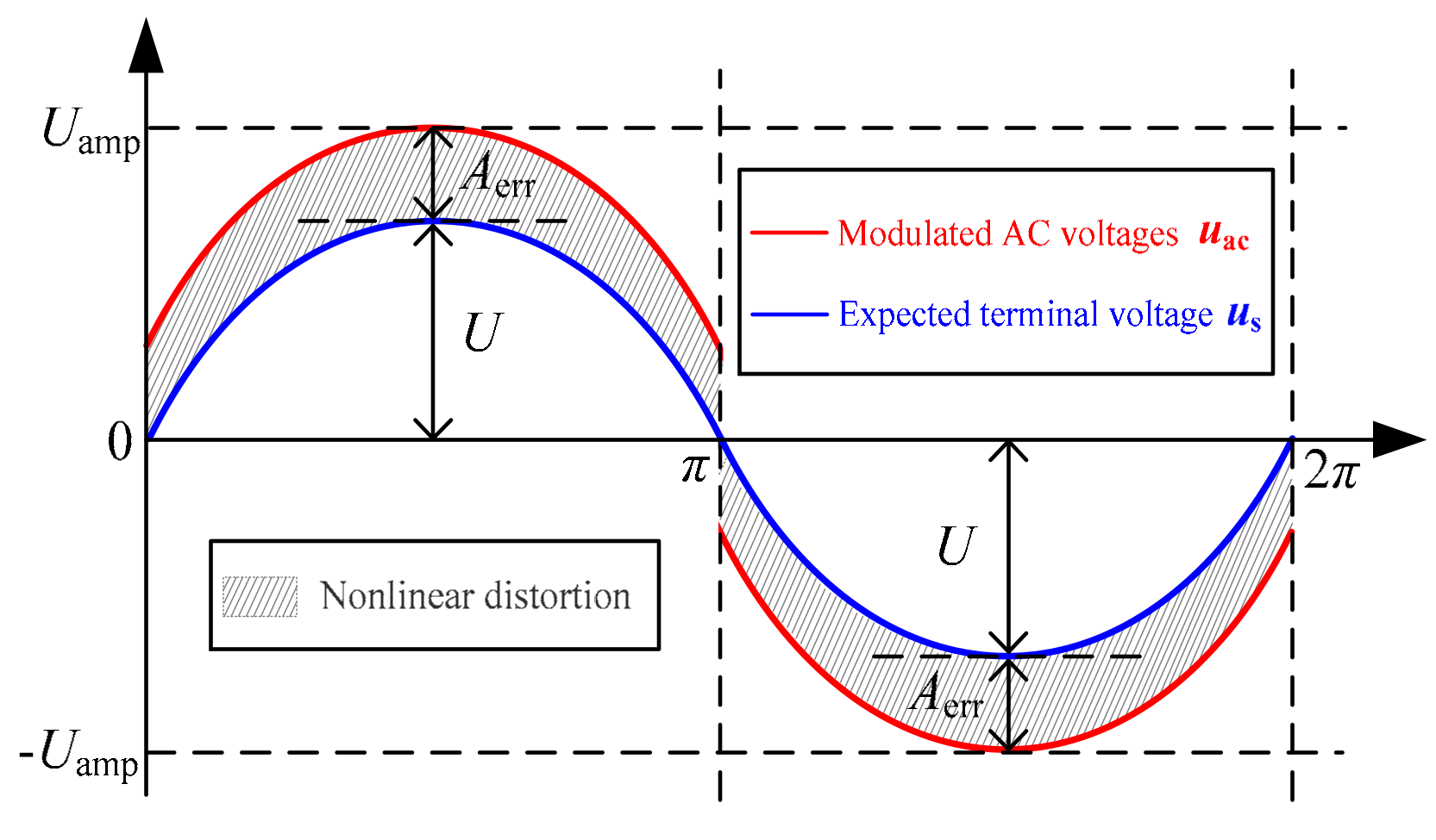
2.2. Nonlinear Distortion of VSI
2.3. Problem Formulation
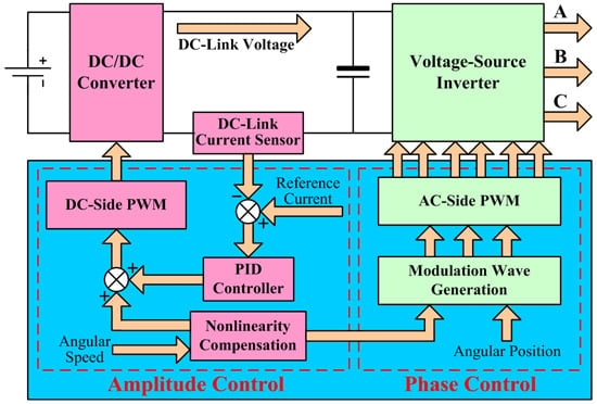
3. Proposed Method
3.1. Design of Reference DC-Link Current
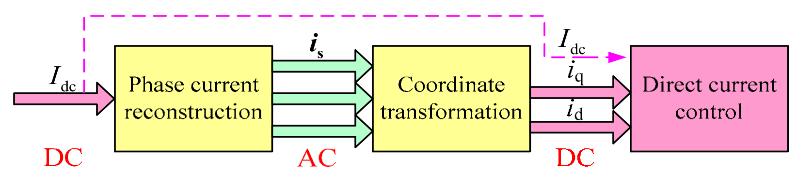
3.2. Implementation of Current Control
3.3. Discussion
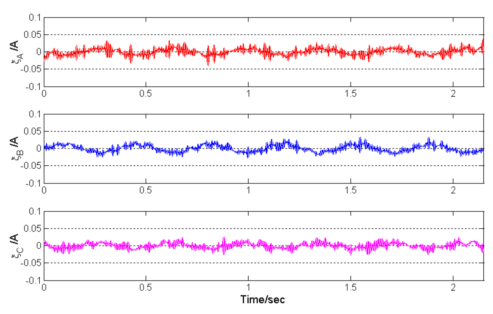
4. Experimental Results
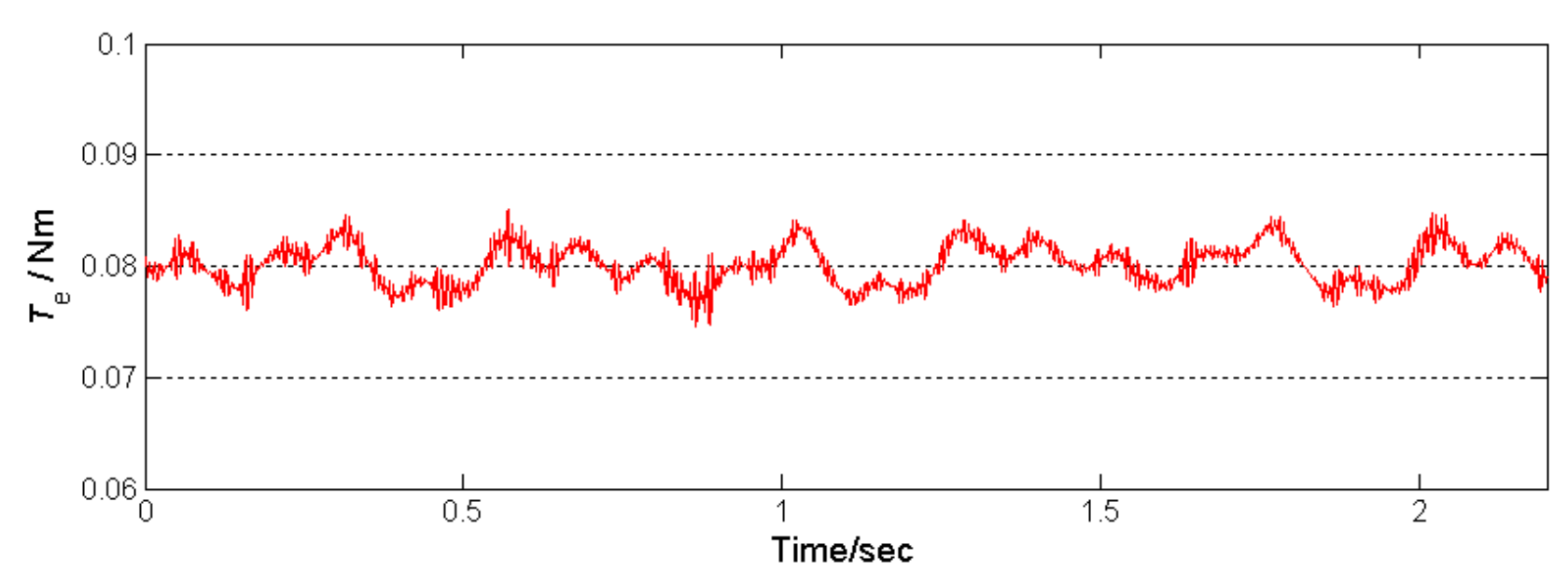
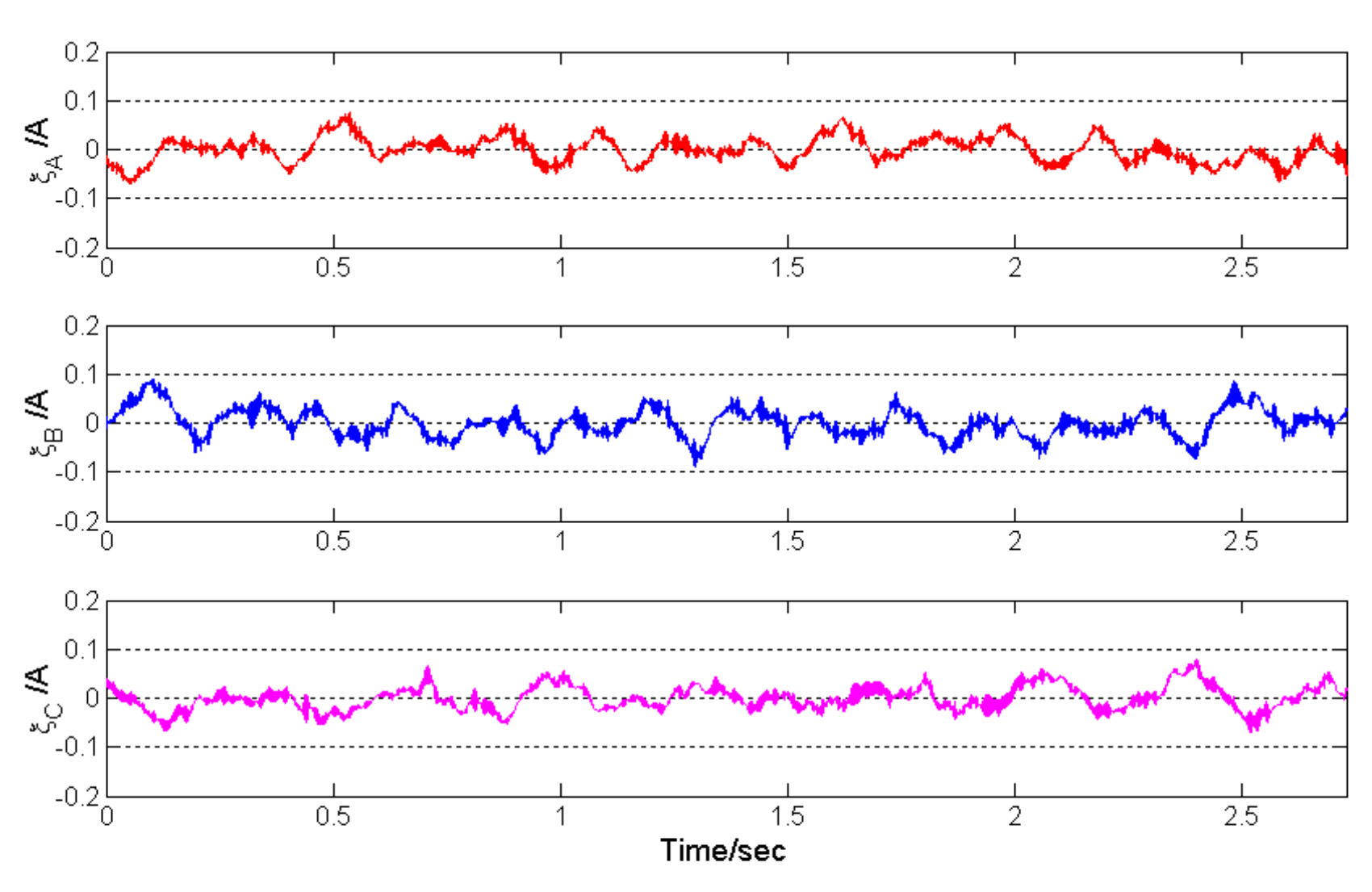
4.1. Current Control With = 0.45 A
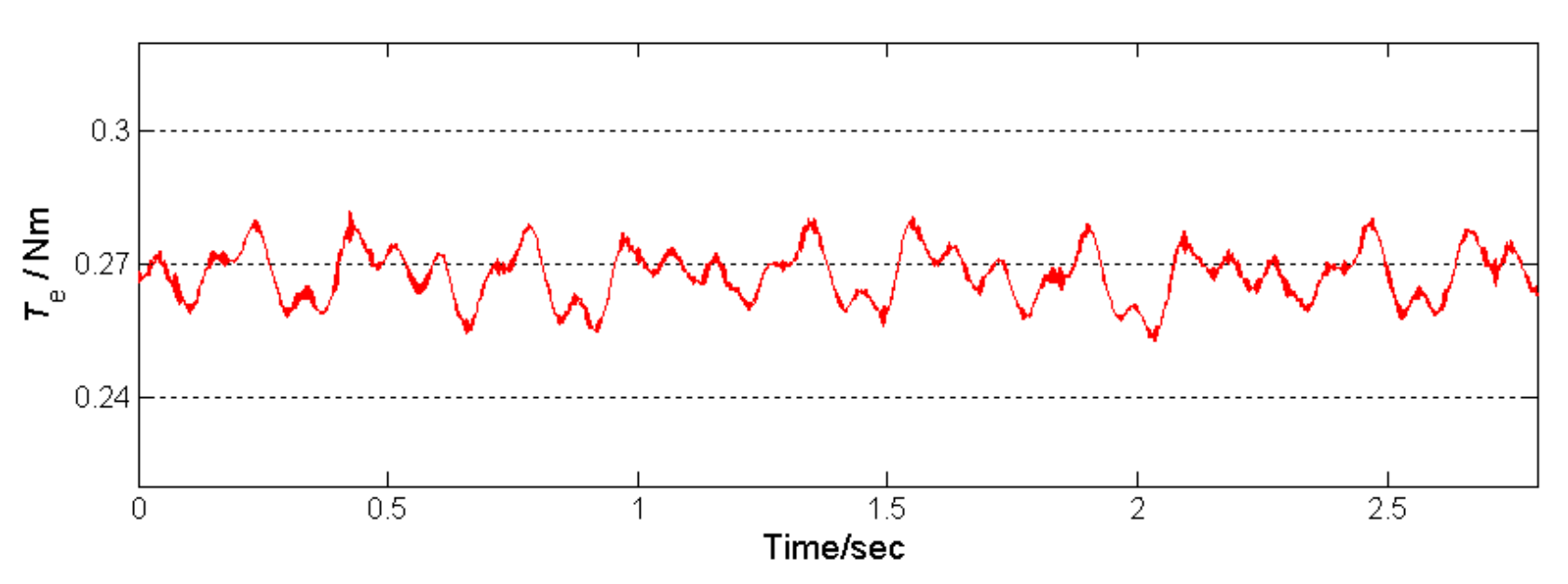
4.2. Current Control With = 1.5 A
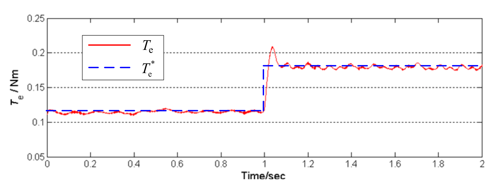
4.3. Current Control With Step Change of
5. Conclusions
Author Contributions
Funding
Conflicts of Interest
References
- Dong, S.; Zhang, Q.; Ma, H.; Wang, R. Design for the interior permanent magnet synchronous motor drive system based on the z-source inverter. Energies 2019, 12, 3350. [Google Scholar] [CrossRef]
- You, Y.-M. Optimal design of PMSM based on automated finite element analysis and metamodeling. Energies 2019, 12, 4673. [Google Scholar] [CrossRef]
- Ye, M.; Shi, T.; Wang, H.; Li, X.; Xia, C. Sensorless-MTPA control of permanent magnet synchronous motor based on an adaptive sliding mode observer. Energies 2019, 12, 3773. [Google Scholar] [CrossRef]
- Lim, D.-K.; Yi, K.-P.; Jung, S.-Y.; Jung, H.-K.; Ro, J.-S. Optimal design of an interior permanent magnet synchronous motor by using a new surrogate-assisted multi-objective optimization. IEEE Trans. Magn. 2015, 51, 8207504. [Google Scholar] [CrossRef]
- Mu, X.; Chen, G.; Wang, X.; Zhao, J.; Wu, W.; Blaabjerg, F. Multi-frequency single loop passivity-based control for LC-filtered stand-alone voltage source inverter. Energies 2019, 12, 4548. [Google Scholar] [CrossRef]
- Xia, C.; Wang, S.; Wang, Z.; Shi, T. Direct torque control for VSI–PMSMs using four-dimensional switching-table. IEEE Trans. Power Electron. 2016, 31, 5774–5785. [Google Scholar] [CrossRef]
- Xu, J.X.; Panda, S.K.; Pan, Y.J.; Lee, T.H.; Lam, B.H. A modular control scheme for PMSM speed control with pulsating torque minimization. IEEE Trans. Ind. Electron. 2004, 51, 526–536. [Google Scholar] [CrossRef]
- Yang, M.; Lang, X.; Long, J.; Xu, D. Flux immunity robust predictive current control with incremental model and extended state observer for PMSM drive. IEEE Trans. Power Electron. 2017, 32, 9267–9279. [Google Scholar] [CrossRef]
- You, Z.C.; Huang, C.H.; Yang, S.M. Online current loop tuning for permanent magnet synchronous servo motor drives with deadbeat current control. Energies 2019, 12, 3555. [Google Scholar] [CrossRef]
- Zhang, X.; Hou, B.; Mei, Y. Deadbeat predictive current control of permanent magnet synchronous motors with stator current and disturbance observer. IEEE Trans. Power Electron. 2017, 32, 3818–3834. [Google Scholar] [CrossRef]
- Pellegrino, G.; Guglielmi, P.; Armando, E.; Bojoi, R.I. Self-commissioning algorithm for inverter nonlinearity compensation in sensorless induction motor drives. IEEE Trans. Ind. Appl. 2010, 46, 1416–1424. [Google Scholar] [CrossRef]
- Liu, K.; Zhu, Z.Q. Online estimation of the rotor flux linkage and voltage-source inverter nonlinearity in permanent magnet synchronous machine drives. IEEE Trans. Power Electron. 2014, 29, 418–427. [Google Scholar] [CrossRef]
- Ludek, B.; Lukas, O. Online adaptive compensation scheme for inverter nonlinearity in PMSM drive. In Proceedings of the 7th International Congress on Ultra Modern Telecommunications and Control Systems and Workshops (ICUMT), Brno, Czech Republic, 6–8 October 2015; pp. 166–171. [Google Scholar]
- Choi, C.; Cho, K.; Seok, J. Inverter nonlinearity compensation in the presence of current measurement errors and switching device parameter uncertainties. IEEE Trans. Power Electron. 2007, 22, 576–583. [Google Scholar] [CrossRef]
- Carpaneto, M.; Fazio, P.; Marchesoni, M.; Parodi, G. Dynamic performance evaluation of sensorless permanent-magnet synchronous motor drives with reduced current sensors. IEEE Trans. Ind. Electron. 2012, 59, 4579–4589. [Google Scholar] [CrossRef]
- Kim, H.; Jahns, T.M. Phase current reconstruction for AC motor drives using a DC link single current sensor and measurement voltage vectors. IEEE Trans. Power Electron. 2006, 21, 1413–1419. [Google Scholar] [CrossRef]
- Lu, J.; Hu, Y.; Zhang, X.; Wang, Z.; Liu, J.; Gan, C. High-frequency voltage injection sensorless control technique for IPMSMs fed by a three-phase four-switch inverter with a single current sensor. IEEE/ASME Trans. Mechatron. 2018, 23, 758–768. [Google Scholar] [CrossRef]
- Li, X.; Dusmez, S.; Akin, B.; Rajashekara, K. A new SVPWM for the phase current reconstruction of three-phase three-level T-type converters. IEEE Trans. Power Electron. 2016, 31, 2627–2637. [Google Scholar] [CrossRef]
- Yan, H.; Xu, Y.; Zou, J. A phase current reconstruction approach for three-phase permanent-magnet synchronous motor drive. Energies 2019, 9, 853. [Google Scholar] [CrossRef]
- Tang, Q.; Shen, A.; Li, W.; Luo, P.; Chen, M.; He, X. Multiple-positions-coupled sampling method for PMSM three-phase current reconstruction with a single current sensor. IEEE Trans. Power Electron. 2020, 35, 699–708. [Google Scholar] [CrossRef]
- Krishnan, R. Permanent Magnet Synchronous and Brushless DC Motor Drives; CRC Press: Boca Raton, FL, USA, 2009. [Google Scholar]
- Zhong, L.; Rahman, M.F.; Hu, W.Y.; Lim, K.W. A direct torque controller for permanent magnet synchronous motor drives. IEEE Trans. Energy Convers. 1999, 14, 637–642. [Google Scholar] [CrossRef]
- Urasaki, N.; Senjyu, T.; Kinjo, T.; Funabashi, T.; Sekine, H. Dead-time compensation strategy for permanent magnet synchronous motor drive taking zero-current clamp and parasitic capacitance effects into account. IEE Proc. Electr. Power Appl. 2005, 152, 845–853. [Google Scholar] [CrossRef]
- Raute, R.; Caruana, C.; Staines, C.S.; Cilia, J.; Sumner, M.; Asher, G.M. Analysis and compensation of inverter nonlinearity effect on a sensorless PMSM drive at very low and zero speed operation. IEEE Trans. Ind. Electron. 2010, 57, 4065–4074. [Google Scholar] [CrossRef]
- Guerrero, J.M.; Leetmaa, M.; Briz, F.; Zamarron, A.; Lorenz, R.D. Inverter nonlinearity effects in high-frequency signal-injection-based sensorless control methods. IEEE Trans. Ind. Appl. 2005, 41, 618–626. [Google Scholar] [CrossRef]
- Salt, D.E.; Drury, D.; Holliday, D.; Griffo, A.; Sangha, P.; Dinu, A. Compensation of inverter nonlinear distortion effects for signal-injection-based sensorless control. IEEE Trans. Ind. Appl. 2011, 47, 2084–2092. [Google Scholar] [CrossRef]
- Lee, J.; Sun, Y. A new SPWM inverter with minimum filter requirement. Int. J. Electron. 1988, 64, 815–826. [Google Scholar] [CrossRef]
- Kang, D.; Lee, Y.; Suh, B.; Choi, C.; Hyun, D. An improved carrier-based SVPWM method using leg voltage redundancies in generalized cascaded multilevel inverter topology. IEEE Trans. Power Electron. 2003, 18, 180–187. [Google Scholar] [CrossRef]
- Fang, J.; Zhou, X.; Liu, G. Instantaneous torque control of small inductance brushless dc motor. IEEE Trans. Power Electron. 2012, 27, 4952–4964. [Google Scholar] [CrossRef]
- Chen, W.; Liu, Y.; Li, X.; Shi, T.; Xia, C. A novel method of reducing commutation torque ripple for brushless DC motor based on cuk converter. IEEE Trans. Power Electron. 2017, 32, 5497–5508. [Google Scholar] [CrossRef]
- Howlader, A.M.; Urasaki, N.; Senjyu, T.; Yona, A. Wide-speed-range optimal PAM control for permanent magnet synchronous motor. In Proceedings of the International Conference on Electrical Machines and Systems, Tokyo, Japan, 15–18 November 2009; pp. 98–102. [Google Scholar]
- Al-nabi, E.; Wu, B.; Zargari, N.R.; Sood, V. Input power factor compensation for high-power CSC fed PMSM drive using d-axis stator current control. IEEE Trans. Ind. Electron. 2012, 59, 752–761. [Google Scholar] [CrossRef]
- Ahmed, A.; Sozer, Y.; Hamdan, M. Maximum torque per ampere control for buried magnet PMSM based on DC-link power measurement. IEEE Trans. Power Electron. 2017, 32, 1299–1311. [Google Scholar] [CrossRef]
- Ou Yang, H.Y.; Lorenz, R.D. Torque ripple minimization in six-step PMSM drives via variable and fast DC bus dynamics. IEEE Trans. Ind. Appl. 2019, 55, 3791–3802. [Google Scholar] [CrossRef]


| Pole Pairs | 2 | Rated Voltage | 3000 r/min |
| Torque coefficient | 0.09 Nm/A | Phase resistance | 1.2 Ω |
| Sliding friction | 0.06 Nm | Phase inductance | 2 mH |
| Statistical Value (Nm) | id = 0 Control | Proposed Method |
|---|---|---|
| P-P value | 0.009646 | 0.010592 |
| Average value | 0.080794 | 0.080149 |
| Standard deviation | 0.001528 | 0.001854 |
| Statistical Value (Nm) | id = 0 Control | Proposed Method |
|---|---|---|
| P-P value | 0.025168 | 0.028928 |
| Average value | 0.269608 | 0.267609 |
| Standard deviation | 0.005123 | 0.005910 |
© 2020 by the authors. Licensee MDPI, Basel, Switzerland. This article is an open access article distributed under the terms and conditions of the Creative Commons Attribution (CC BY) license (http://creativecommons.org/licenses/by/4.0/).
Share and Cite
Wang, K.; Wu, Z.; Chu, Z. DC-Link Current Control with Inverter Nonlinearity Compensation for Permanent Magnet Synchronous Motor Drives. Energies 2020, 13, 546. https://doi.org/10.3390/en13030546
Wang K, Wu Z, Chu Z. DC-Link Current Control with Inverter Nonlinearity Compensation for Permanent Magnet Synchronous Motor Drives. Energies. 2020; 13(3):546. https://doi.org/10.3390/en13030546
Chicago/Turabian StyleWang, Kan, Zhong Wu, and Zhongyi Chu. 2020. "DC-Link Current Control with Inverter Nonlinearity Compensation for Permanent Magnet Synchronous Motor Drives" Energies 13, no. 3: 546. https://doi.org/10.3390/en13030546
APA StyleWang, K., Wu, Z., & Chu, Z. (2020). DC-Link Current Control with Inverter Nonlinearity Compensation for Permanent Magnet Synchronous Motor Drives. Energies, 13(3), 546. https://doi.org/10.3390/en13030546