Article

Design and Analysis of a Permanent Magnet Synchronous Motor Considering Axial Asymmetric Position of Rotor to Stator †

1
Energy and Power Conversion Engineering, University of Science and Technology, Daejeon 34113, Korea
2
Electric Machines and Drives Research Center, Korea Electrotechnology Research Institue, Changwon 51543, Korea
*
Author to whom correspondence should be addressed.
This paper is an extended version of our paper published in 2018 International Conference on Electrical Machines and Systems (ICEMS), Jeju-do, South Korea, 7–10 July 2018; pp. 37–40.
Energies 2019, 12(24), 4816; https://doi.org/10.3390/en12244816
Submission received: 23 October 2019 / Revised: 13 December 2019 / Accepted: 16 December 2019 / Published: 17 December 2019
(This article belongs to the Special Issue Permanent Magnet Electrical Machines)

Abstract

:
This paper presents the design and analysis of a permanent magnet synchronous motor (PMSM) considering the axial asymmetric PM overhang for a smart actuator (SA) application such as an isokinetic exercise machine. This structure helps take advantage of the motor space effectively and makes the system small in size and light in weight. However, two drawbacks related to the performance of motor occur when the axial asymmetric PM overhang is used: (1) an axial attractive force (AAF) is created, which can produce motor noise and vibration; (2) the torque of motor is reduced compared with the symmetric PM overhang model. We used five steps to solve these problems. Firstly, the AAF according to the variation in axial position of the rotor to the stator was calculated and analyzed. Secondly, the torque was calculated under the same conditions to confirm that the system requirements were satisfied. The three-dimensional finite element analysis was used to determine the AAF and torque. Thirdly, the appropriate axial position of the rotor to the stator was suggested considering the analysis results and space inside the housing. Next, the commercial bearing type was chosen so that the total force acting on the bearing was below the bearing load limit to ensure motor stability. Finally, a prototype model was made and tested to confirm the accuracy of the analytical results. Through this study, by using the axial asymmetric PM overhang, the total length of SA was reduced by 5mm and the performance of motor was guaranteed.

1. Introduction

Smart actuators (SAs) composed of modules integrating an electric motor, gear reducer, and controller, which are widely developed as driving modules for robots, are used in many applications to make the compact system. In this study, we examined when SAs are used as an electrical load on an isokinetic exercise machine (IEM), and described the design and analysis of the electric motor that constitutes the SA.
IEM is a machine that controls the speed of contraction within the range of motion. It is widely used in rehabilitative activities or sports rehabilitation [1]. The main components of an IEM system are shown in Figure 1a. The electric load mainly consists of a controller, electric motor, and reduction gear. Conventionally, the three main components of the electric load are placed separately, creating the conventional electric load, as shown in Figure 1b. However, since the space for the system is limited, using a SA type electric load is useful, as shown in Figure 2. The SA module may help simplify the system structure, improve reliability, and create a compact system [2]. Researchers are interested in the permanent magnet synchronous motor (PMSM) design for SA module to achieve high efficiency and high power density, which can be designed using optimal design techniques or the PM overhang to generate more magnetic flux in the air-gap [3,4,5,6,7,8,9,10,11,12,13,14,15,16]. Most PMSMs use a PM overhang structure in the rotor to operate the Hall effect sensor for cost-saving and a simplified motor structure [4].
Kang et al. [5] investigated the asymmetric PM overhang effect from the view point of Z-axis thrust, vibration, and noise. Chun et al. [6] analyzed the effect of symmetric and asymmetric PM overhang on the linkage fluxes of the stator and axial magnetic forces. In this study, we investigated the axial asymmetric position of the rotor with PM overhang to stator with the aim of providing more space inside the motor. Figure 3a depicts the half cross-section view of symmetric brushless PMSM. As shown in Figure 3b, the space (I) at the rear of the motor is only used for containing end-winding, coil connections, and the Hall effect sensor board, so the mechanical and controller parts must be placed in the other areas. If the axial asymmetry of the PM overhang is used, the area (II) is freed up and can be used for bearings and supporting parts. This study was developed from Luu et al. [17], providing a more detailed and clear explanation of the theory and analytical results along with additional experimental results.
The use of PM overhang has a positive effect on the performance of the motor; however, the asymmetric PM overhang breaks the axial magnetic symmetry of motor and reduces the magnetic torque. This generates an axial attractive force (AAF). AAF can damage the bearing and create noise and vibration [5]. Therefore, we investigated the value of AAF according to the axial position of the rotor to the stator. The torque value is also affected by the asymmetric PM overhang, so we calculated the torque to ensure that the system requirement was satisfied. Both AAF and torque were determined using three-dimensional finite element analysis (3-D FEA). Afterward, the commercial bearing was selected to ensure the stability of the motor. Considering the analysis results together with the actual dimension of the motor, the appropriate axial position of the rotor to the stator was determined. Finally, the analysis results were validated by the experiment.

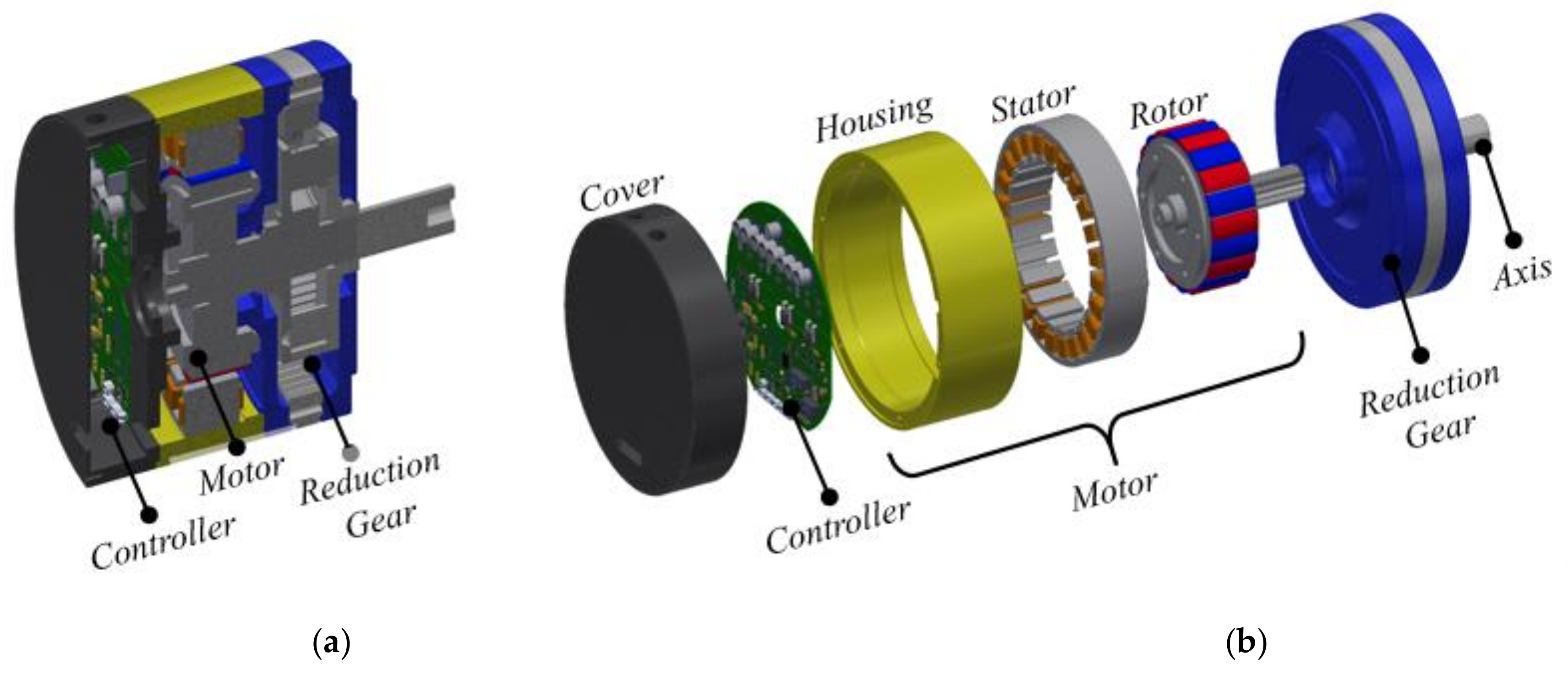
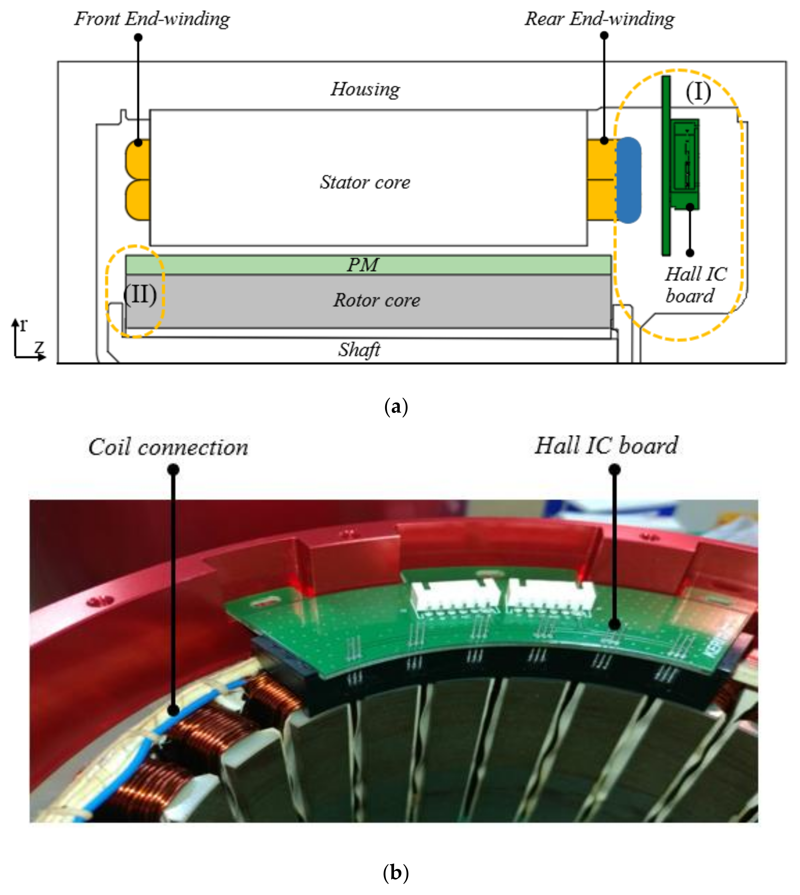
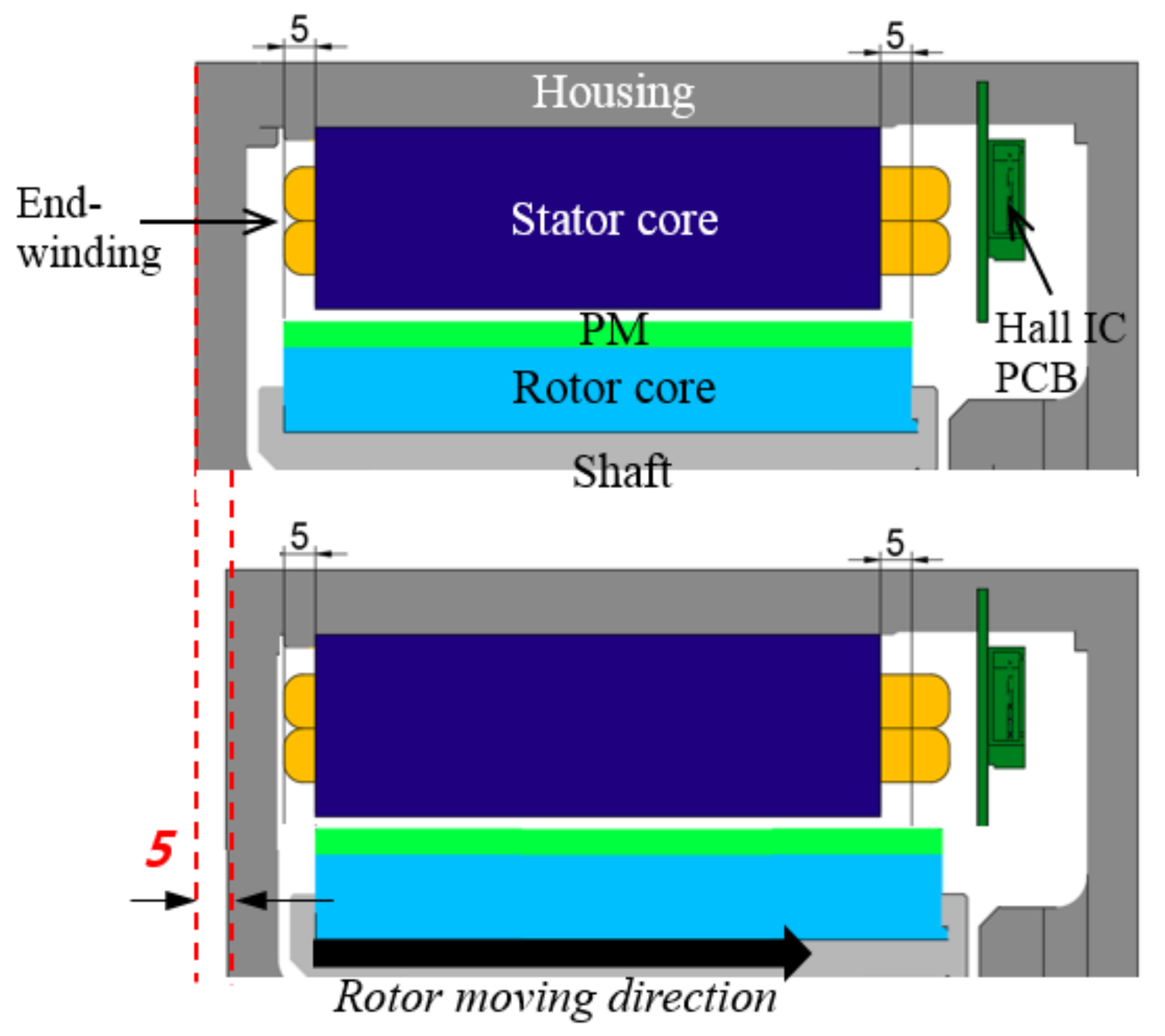
2. Proposed Model Description

Several periodically 3-D analysis models of the PM motor with different rotor core to stator core positions are shown in Figure 4, in which Dx is the distance between the mechanical centers of the rotor and stator. The motor is symmetrical when Dx = 0 mm, i.e. the symmetrical model has a 5mm of PM overhang on both sides. The concentrated winding with the 20-pole and 24-slot model is designed to have lower end-winding length and lower copper loss. The axial length of the rotor is 10 mm longer than the stator’s axial length, i.e., 5 mm of PM overhang for each side in the axial symmetrical model. The design target is to meet the rated torque requirement and obtain high efficiency. Table 1 shows the output performance requirements and dimensions of the motor.

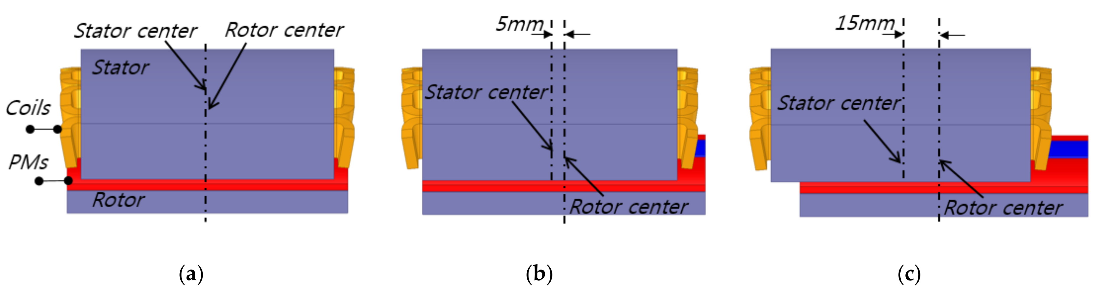
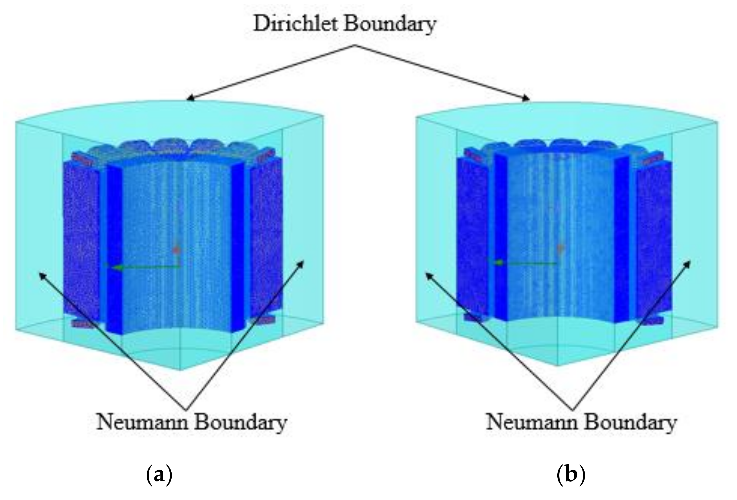
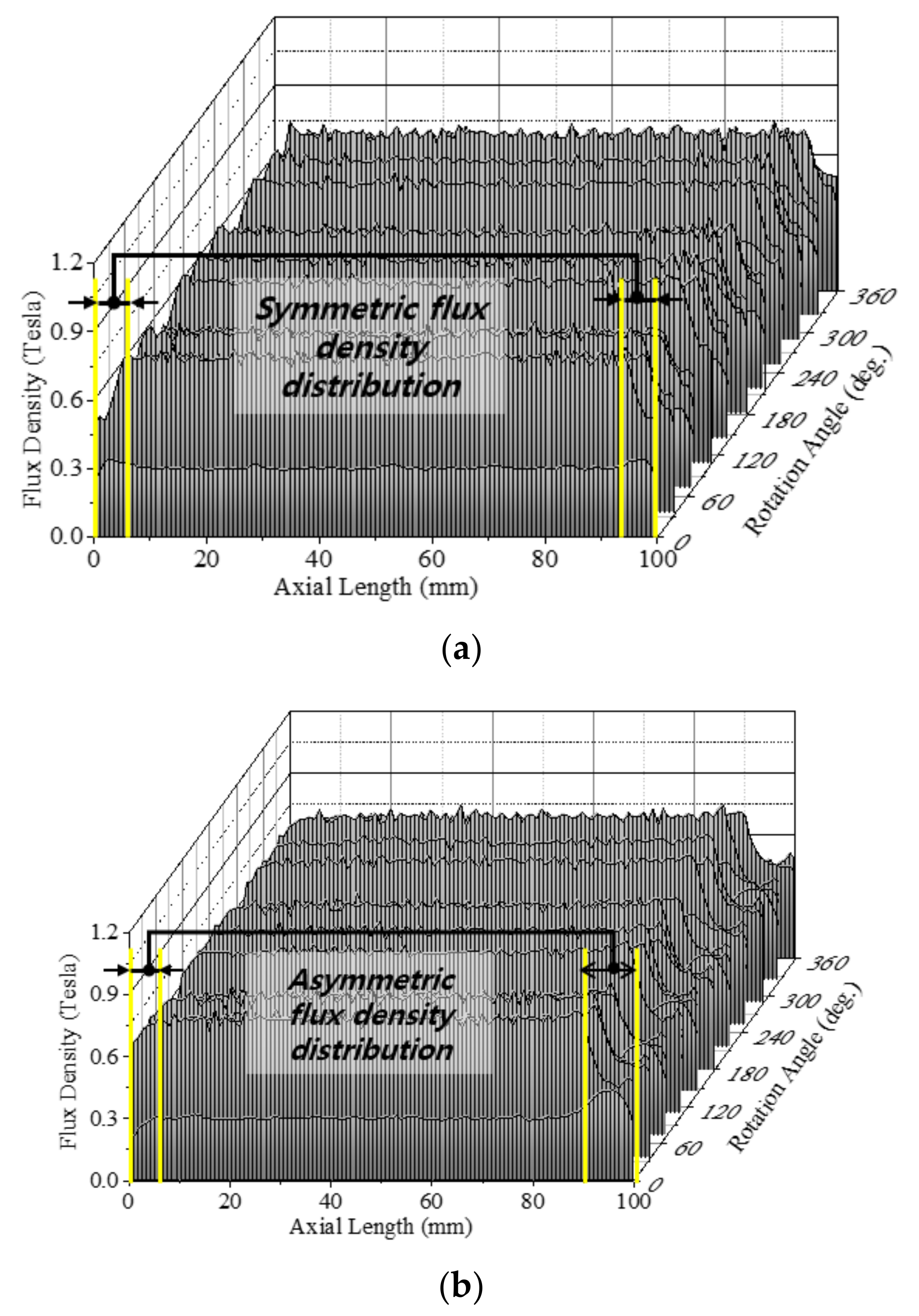
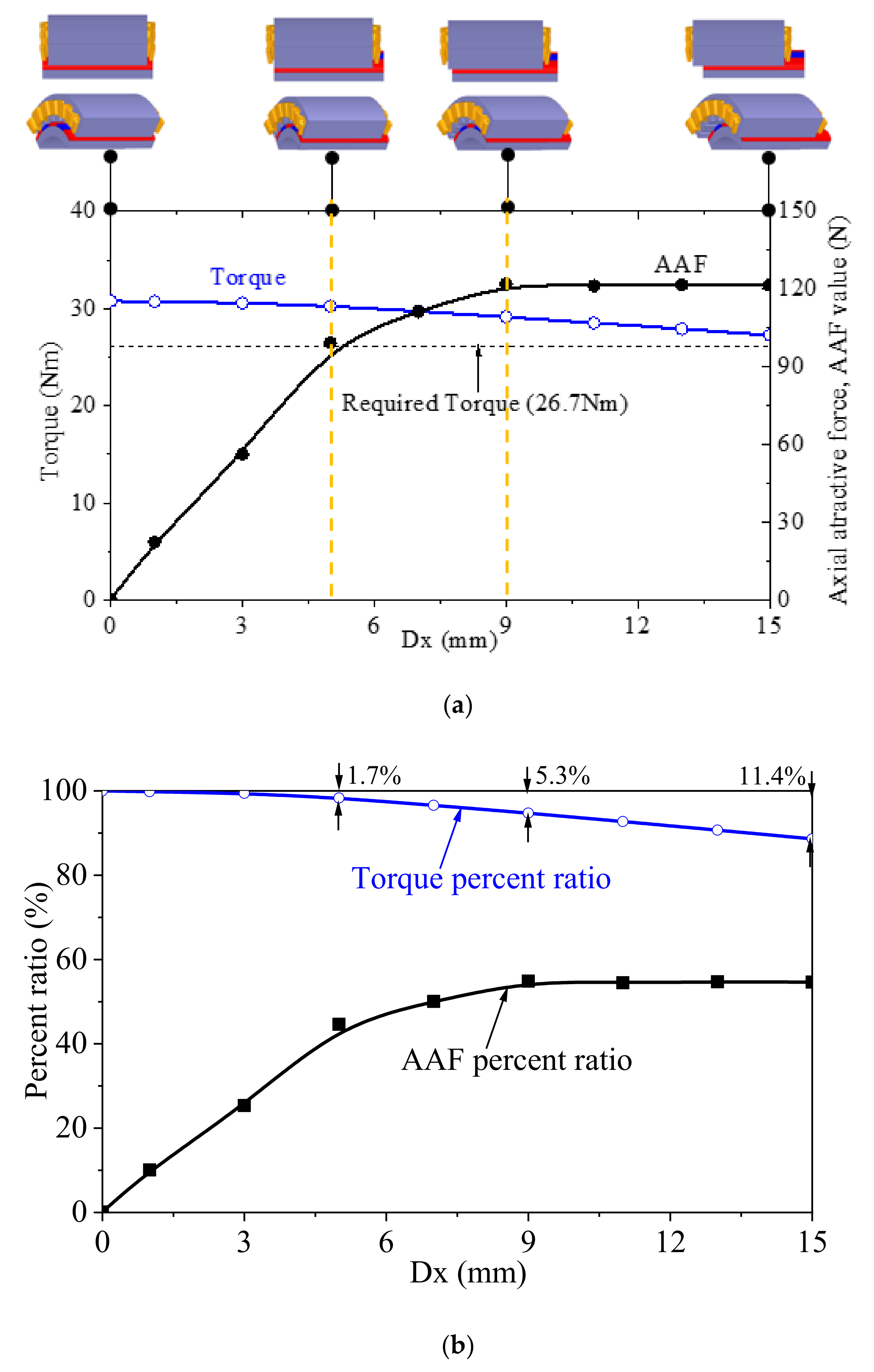
3. AAF Analysis Due to Asymmetric PM Overhang

Due to the asymmetric configuration, the 3-D FEA was used to calculate the AAF values. The magnetic field can be solved using commercial software (3D Maxwell, ANSYS, Inc., USA). The virtual work method is used to determine the axial attractive force and magnetic torque [18].
W m a g = 1 2 B . H d V
A A F = W m a g z
T = W m a g θ = F θ × R r o t o r
where Wmag is the total stored magnetic energy, B is the magnetic flux density, H is the magnetic field, z is the axial displacement, Fθ is the force in the θ -direction, and Rrotor is the radius of the outer rotor.
Figure 5 shows the periodical 3-D analysis models of the PM motor. Since the model has a fractional slot per pole configuration, which is 20-pole and 24-slot, a 1/4 periodic of the machine was modeled in 3-D FEA. The Neumann boundary condition was applied to reduce the analysis time. The model with symmetrical PM overhang has a 5 mm on both sides. The air-gap flux density distribution in both symmetric and asymmetric models is shown in Figure 6. In the case of the symmetric model, the air-gap flux density is distributed symmetrically on both sides of the overhang region. In contrast, the asymmetric model generates asymmetrical flux, which produces AAF and motor vibration.
With variation in Dx, the value of AAF is as shown in Figure 7a. AAF is 0 N when Dx = 0, indicating that motor is symmetrical. AAF increases dramatically when Dx is less than 9 mm. After that point, AAF tends to be constant. The torque gradually decreases by about 11.4% when Dx increases from 0 to 15 mm.
For a more visual perspective of the change in AAF and torque according to the variation in Dx, torque was normalized at Dx = 0mm and AAF was normalized on the basis of Fθ at Dx = 0 mm, which are defined as torque percent ratio and AAF percent ratio, respectively, as shown in Figure 7b. The torque percent ratio decreases slightly as Dx increases from 0 to 3 mm, and increases dramatically as Dx is over 3 mm. On the contrary, the AAF percent ratio significantly increases by 20% as Dx changes from 0 to 3 mm and remains at almost 50% of Fθ when Dx is over 3 mm.
To choose the proper position of the rotor to the stator, the bearing position and space inside the housing should be considered. Combined with the analysis results, we find that 5 mm is a reasonable axial position of the rotor to the stator, as shown in Figure 8. At Dx of 5 mm, the torque is 30.26 Nm, which satisfies the system requirements.

4. Bearing Selection Considering Axial Attractive Force

To select the correct bearing for each application, several factors need to be considered, such as allowable space, bearing load (magnitude, direction), and rotational speed. For this studied motor, both axial and radial forces act upon the bearing. In the previous section, the axial force caused by axial asymmetry of the motor was determined, which is 99.27 N. We assumed that the motor is ideally symmetrical in the radial direction; thus the radial magnetic forces eliminate each other on the bearing. Therefore, the weight of the rotor and the rotational force (tangential component of the force) that generates the motor torque are considered radial loads. Since the maximum torque is less than twice the rated torque and the main operating point is the rated torque range, the rotational force was calculated based on the rated torque. To consider the maximum load on both bearings, we used the case where the direction of gravity to the rotor coincides with the direction of rotational force. The radial load was calculated by multiplying the sum of these two loads by a load factor of 1.2 (the value for the environment with little external impact on the shaft [19]). The load acting on each bearing was calculated using the moment equilibrium equation [19,20]. We chose deep groove ball bearings in this study because they can carry both axial and radial loads and have outstanding noise and vibration characteristics. Since the inner ring rotates, the value of the rotational coefficient V is 1 in Equation (4), so the equation of equivalent load on the ball bearing is as expressed in Equation (5).
The dynamic equivalent radial load acting on the ball bearing is calculated by [20]
Pr = X.V.Fr + Y.Fa
Pr = X.Fr + Y.Fa = 0.496 kN
where
  • Pr is the dynamic equivalent radial load N,
  • Fr is the actual radial load N,
  • Fa is the actual axial load N,
  • X is the radial load factor,
  • Y is the axial load factor, and
  • V is the rotational factor.
The values for X and Y are listed in the bearing table provided by the manufacturer [20].
Considering the allowable space for the bearing and the bearing load limit, we used the 6205-ZZ bearing (NTN Bearing Corporation, Japan) in this study.

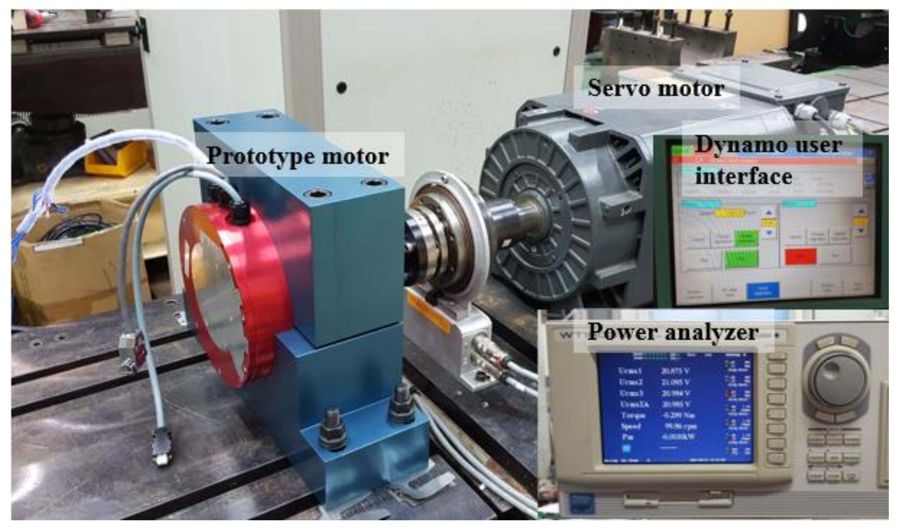
5. Experimental Validation

5.1. Resistance and Back Electromotive Force Comparison

To check whether the prototype was manufactured exactly as the designed model, the resistance and back electromotive force (back EMF) were measured using a dynamo system as shown in Figure 9. The data were acquired using the dynamo user interface and power analyzer. Table 2 presents the comparison of phase resistance and back EMF between the calculated values and experiment results for the symmetrical model. It was clearly observed that the error between the calculated and measured values was acceptable, at under 5%.

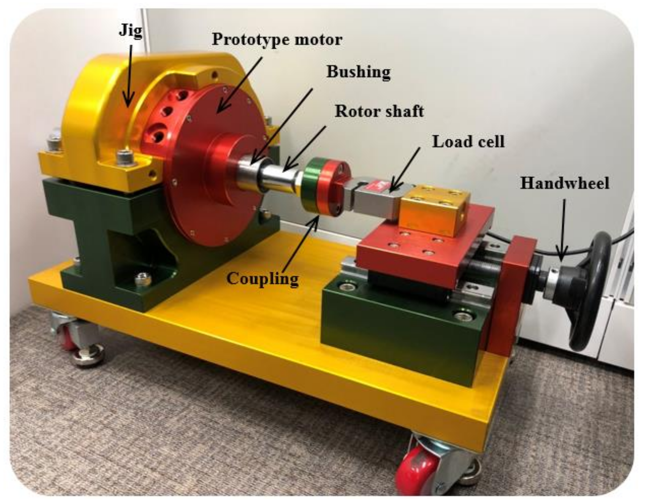
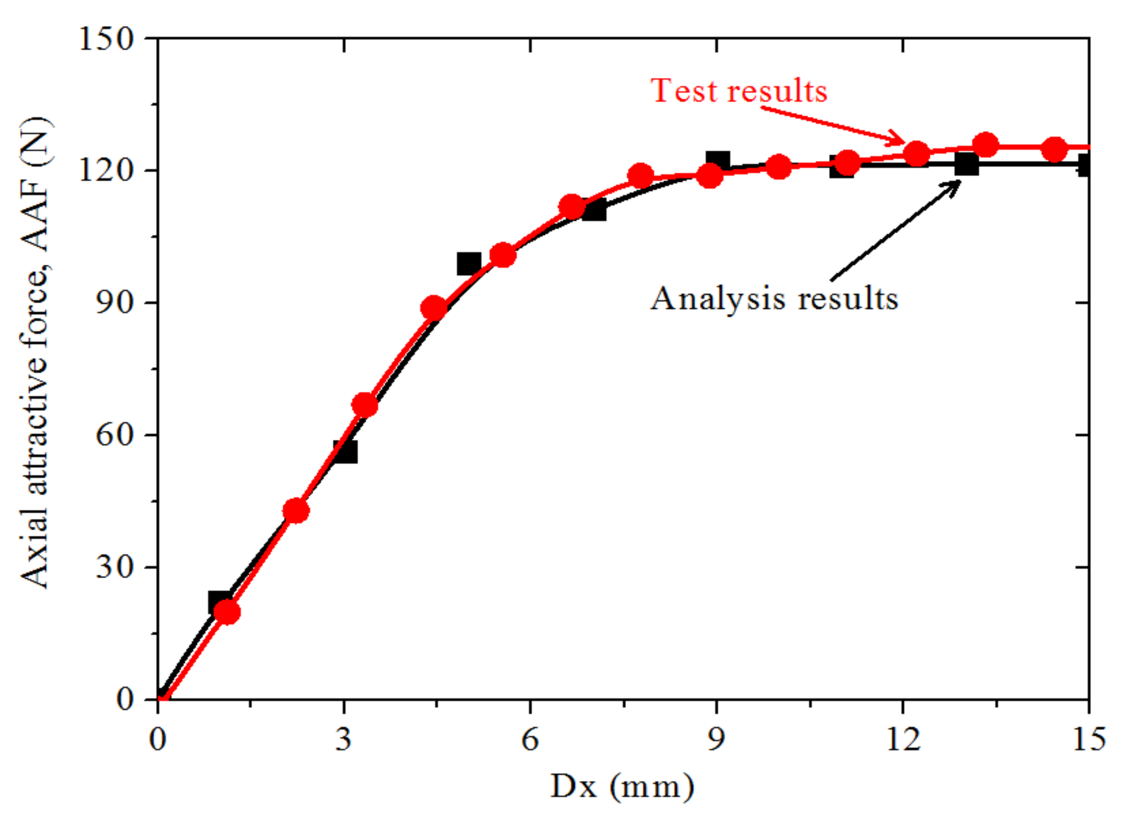
5.2. Measurement of Axial Attractive Force

The force measurement system was set up, as illustrated in Figure 10. The load cell (BDHS–1t) was used to measure the AAF value. A coupling is used to connect the motor shaft with the hand-wheel. When the hand-wheel turns in the clockwise direction, the rotor moves along the +z-direction, and vice versa. Each 180° rotation of the hand-wheel, the rotor linearly moves 1.1 mm. Therefore, the AAF depending on the rotor position with respect to stator core was measured.
The comparison between the calculated and experimental values is shown in Figure 11. The AAF value increases as the axial position of the rotor core to the stator core increases. Similar to the analysis results, the measured value tended to be constant when Dx exceeded 9 mm. The experiment results are consistent with the analysis results.

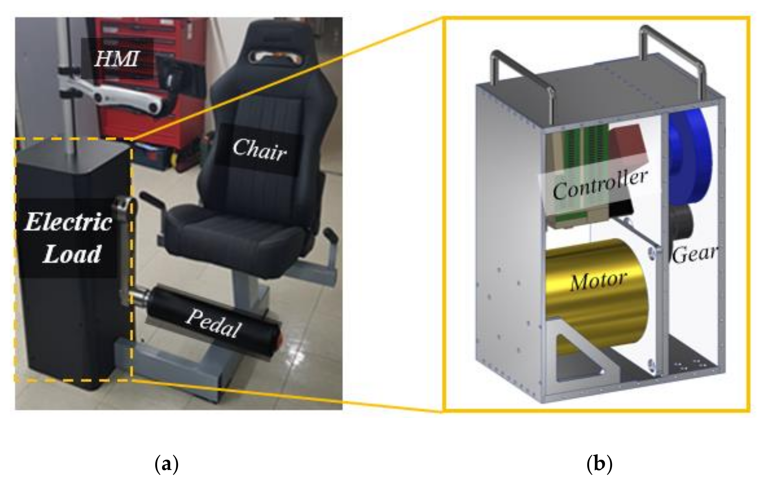
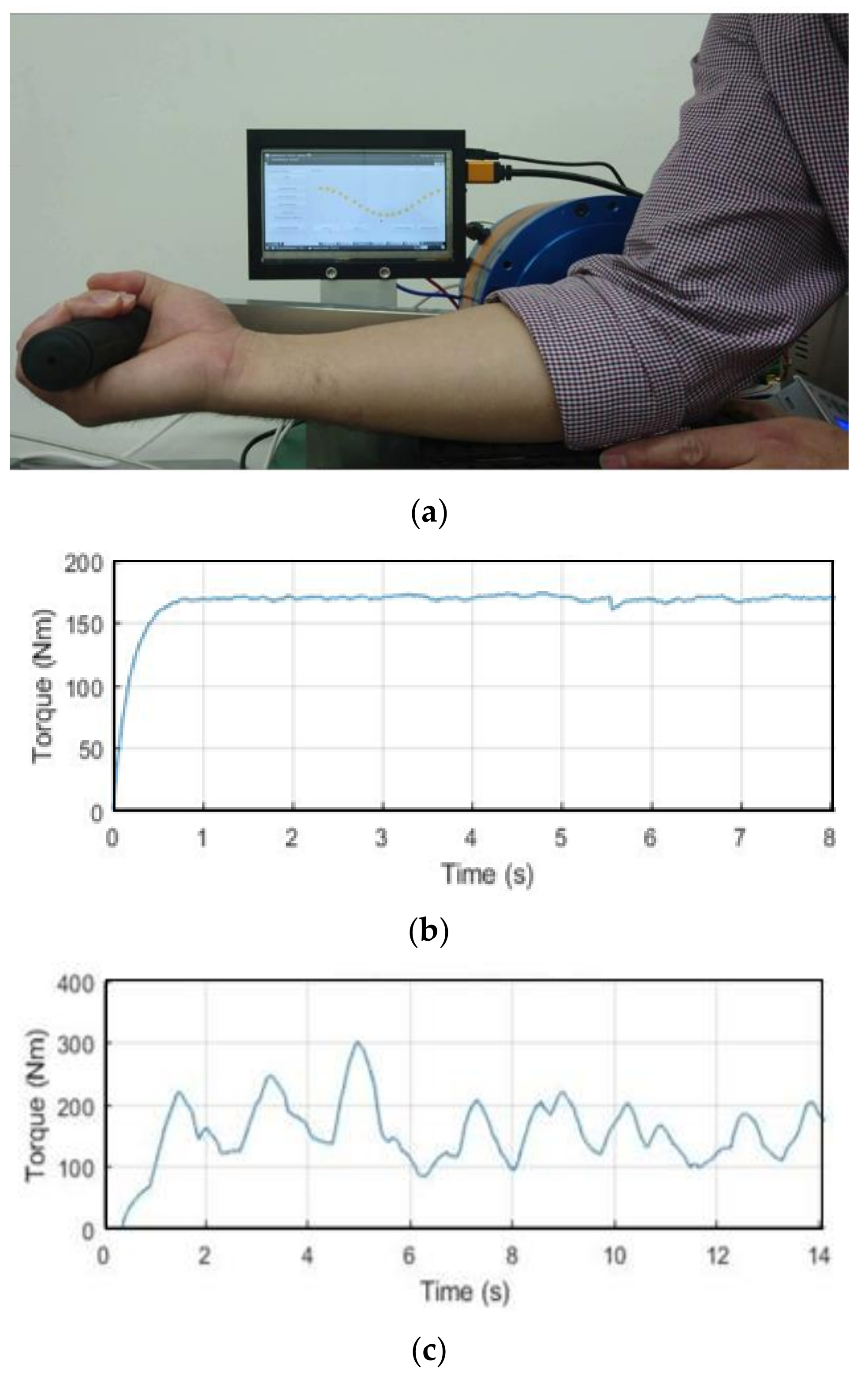
5.3. Isokinetic Exercise Machine Test

After the motor had been tested separately, it was assembled together with a controller and reduction gear to create the smart actuator type electric load as shown in Figure 2. Both isotonic exercise mode and isokinetic exercise mode tests were implemented to check the performance of the system, as shown in Figure 12a. In the isotonic mode, the same force is applied in the pedal and the value of force depends on selecting a resistance between 0 to 100%, while in the isokinetic mode, the constant speed is maintained regardless of the force exerted in the pedal. Both help to increase muscle endurance and muscle strength. In addition, training in the isokinetic mode also reduces the risk of injury. The torque value was measured in the two training modes and results are shown in Figure 12b,c. The experiments show that the isokinetic exercise machine works well in both training modes.

6. Conclusions

In this paper, the design and analysis of a PMSM were proposed considering the axial asymmetric position of the rotor to the stator for efficient use of space inside the motor. Due to the axially asymmetrical motor, the Z-thrust force appeared, which may cause motor noise and vibration, and torque was reduced. To maintain the performance of motor, we numerically and experimentally investigated the axial force and torque according to the axial position of the rotor to the stator. Considering the available space for the bearing, and the simulation results, we found that 5mm is the axial offset position of rotor core center to the stator core center, which means that the axial length of the motor can be decreased by up to 5mm. At a 5 mm of the axial offset position of the rotor to the stator, torque was reduced by 1.7% in comparison to the symmetric overhang PM model, which still met the system requirement. The process of how to choose a bearing to maintain the stability of the motor was also presented.

Author Contributions

Conceptualization, J.-Y.L. and P.T.L.; software, P.T.L.; validation, J.-H.L.; writing, P.T.L.; supervision, J.-Y.L.; project administration, B.-C.W.

Funding

This research was supported by Korea Electrotechnology Research Institute (KERI) Primary research program through the National Research Council of Science and Technology (NST) funded by the Ministry of Science and ICT (MSIT), grant number: 19-12-N0101-18.

Conflicts of Interest

The authors declare no conflict of interest.

References

  1. Kikuchi, T.; Oda, K.; Ohyama, Y.; Isozumi, S.; Furusho, J. Development of isokinetic exercise system using high performance MR fluid brake. In Proceedings of the 2009 IEEE International Conference on Mechatronics, Malaga, Spain, 14–17 April 2009; pp. 1–6. [Google Scholar]
  2. Luu, P.T.; Lee, J.-Y.; Lee, J.-H.; Park, J.-W. Electromagnetic and Thermal Analysis of Permanent-Magnet Synchronous Motors for Cooperative Robot Applications. IEEE Trans. Magn. 2019. [Google Scholar] [CrossRef]
  3. Kim, K.-C.; Koo, D.-H.; Lee, J. The Study on the Overhang Coefficient for Permanent Magnet Machine by Experimental Design Method. IEEE Trans. Magn. 2007, 43, 2483–2485. [Google Scholar] [CrossRef]
  4. Woo, D.-K.; Jeong, B.H. Irreversible Demagnetization of Permanent Magnet in a Surface-Mounted Permanent Magnet Motor with Overhang Structure. IEEE Trans. Magn. 2016, 52, 1–6. [Google Scholar] [CrossRef]
  5. Kang, G.-H.; Son, Y.-D.; Kim, G.-T. The Noise and Vibration Analysis of BLDC Motor Due to Asymmetrical Permanent-Magnet Overhang Effects. IEEE Trans. Ind. Appl. 2008, 44, 1569–1577. [Google Scholar] [CrossRef]
  6. Chun, J.-D.; Lee, J.; Wakao, S. Overhang effect analysis of brushless DC motor by 3-D equivalent magnetic circuit network method. IEEE Trans. Magn. 2003, 39, 1610–1613. [Google Scholar] [CrossRef]
  7. Lee, J.-Y.; Hong, D.-K.; Woo, B.-C.; Joo, D.-S.; Chio, Y.-H.; Nam, B.-U. Unbalanced Magnetic Force Calculation for Assembly Jig Design. IEEE Trans. Magn. 2012, 48, 4224–4227. [Google Scholar] [CrossRef]
  8. Woo, D.-K.; Lim, D.-K.; Yeo, H.-K.; Ro, J.-S.; Jung, H.-K. A 2-D Finite-Element Analysis for a Permanent Magnet Synchronous Motor Taking an Overhang Effect into Consideration. IEEE Trans. Magn. 2013, 49, 4894–4899. [Google Scholar] [CrossRef]
  9. Seo, J.-M.; Jung, I.-S.; Jung, H.-K.; Ro, J.-S. Analysis of Overhang Effect for a Surface-Mounted Permanent Magnet Machine Using a Lumped Magnetic Circuit Model. IEEE Trans. Magn. 2014, 50, 1–7. [Google Scholar]
  10. Song, J.-Y.; Lee, J.H.; Kim, Y.-J.; Jung, S.-Y. Computational Method of Effective Remanence Flux Density to Consider PM Overhang Effect for Spoke-Type PM Motor With 2-D Analysis Using Magnetic Energy. IEEE Trans. Magn. 2016, 52, 1–4. [Google Scholar] [CrossRef]
  11. Yu, D.; Huang, X.; Wu, L.; Fang, Y. Design and Analysis of Outer Rotor Permanent-Magnet Vernier Machines with Overhang Structure for In-Wheel Direct-Drive Application. Energies 2019, 12, 1238. [Google Scholar] [CrossRef] [Green Version]
  12. Kim, W.-H.; Jang, I.-S.; Jin, C.-S.; Lee, J.; Lee, S.-G. Design of Novel Overhang Structure for Separated Pole-Piece Type Ferrite Magnet Motor. IEEE Trans. Magn. 2015, 51, 1–4. [Google Scholar]
  13. Yeo, H.-K.; Lim, D.-K.; Woo, D.-K.; Ro, J.-S.; Jung, H.-K. Magnetic Equivalent Circuit Model Considering Overhang Structure of a Surface-Mounted Permanent-Magnet Motor. IEEE Trans. Magn. 2015, 51, 1–4. [Google Scholar]
  14. Yeo, H.-K.; Lim, D.-K.; Jung, H.-K. Magnetic Equivalent Circuit Model Considering the Overhang Structure of an Interior Permanent-Magnet Machine. IEEE Trans. Magn. 2019, 55, 1–4. [Google Scholar] [CrossRef]
  15. Park, J.-H.; Jung, K.-T.; Jung, Y.-H.; Lim, M.-S.; Yoon, M.-H.; Hong, J.-P.; Jung, J.-W. Design and Verification for the Torque Improvement of a Concentrated Flux-Type Synchronous Motor for Automotive Applications. IEEE Trans. Ind. Appl. 2019, 55, 3534–3543. [Google Scholar] [CrossRef]
  16. Lee, J.-G.; Yeo, H.-K.; Jung, H.-K.; Kim, T.-K.; Ro, J.-S. Electromagnetic and thermal analysis and design of a novel-structured surface-mounted permanent magnet motor with high-power-density. IET Electr. Power Appl. 2019, 13, 472–478. [Google Scholar] [CrossRef]
  17. Luu, P.T.; Lee, J.-Y.; Hwang, W.; Woo, B.-C. A Design Approach Considering Axial Asymmetry Position of Rotor to Stator in Permanent Magnet Synchronous Motor for Compact Size. In Proceedings of the 2018 21st International Conference on Electrical Machines and Systems (ICEMS), Jeju, Korea, 7–10 October 2018; pp. 37–40. [Google Scholar]
  18. Ansys Corporation. “Maxwell online help”, Maxwell 18.0. Available online: https://www.scribd.com/document/370055766/Ansys-Maxwell-18-Online-Help (accessed on 23 October 2019).
  19. Park, C.H.; Ham, S.Y.; Hong, D.E.; Kim, J.K. Development of High Speed Spindle for Machine Tool with Magnetic Bearings. Trans. Korean Soc. Noise Vib. Eng. 2015, 25, 895–900. [Google Scholar] [CrossRef]
  20. NTN Bearing Corporation. “Ball and Roller Bearing Catalog”. Available online: http://www.ntnamericas.com/en/brochures-and-literature/catalogs/164 (accessed on 23 October 2019).
Figure 1. (a) Isokinetic exercise machine system and (b) conventional electric load.
Energies 12 04816 g001
Figure 2. Smart actuator type electric load: (a) cross-section view and (b) close-up view.
Energies 12 04816 g002
Figure 3. (a) Half cross-section view of brushless PMSM, (b) coil connection and Hall effect sensor board in brushless PMSM prototype.
Energies 12 04816 g003
Figure 4. Periodic three-dimensional (3-D) analysis model, when Dx, which is the distance between the stator center and rotor center, is (a) 0, (b) 5, and (c) 15 mm.
Energies 12 04816 g004
Figure 5. Periodically analysis model by using 3-D finite element analysis (FEA) (number of triangle elements is about 400,000): (a) symmetrical and (b) asymmetrical models.
Energies 12 04816 g005
Figure 6. Air-gap flux density distribution: (a) symmetrical model and (b) asymmetrical model.
Energies 12 04816 g006
Figure 7. (a) The change in axial attractive force (AAF) and torque values according to the variation in Dx, and (b) AAF and torque percent ratio.
Energies 12 04816 g007
Figure 8. The axial cross-section of the motor in r-z plane when (top) Dx = 0 mm and (bottom) Dx = 5 mm) (unit: mm).
Energies 12 04816 g008
Figure 9. The experimental setup to measure the back electromotive force value.
Energies 12 04816 g009
Figure 10. The experimental setup for the measurement of AAF.
Energies 12 04816 g010
Figure 11. Comparison between measured and analyzed results.
Energies 12 04816 g011
Figure 12. (a) Isokinetic exercise machine operation test for elbow joint exercise, (b) torque waveform in the isotonic training mode, and (c) torque waveform in the isokinetic training mode.
Energies 12 04816 g012
Table 1. Specifications of the analysis model.
SpecificationsValueUnit
Output requirementRated output power
(Continuous operation)
1.5kW
Maximum output power
(instantaneous operation, 30s)
4.5kW
Rated speed540rpm
Rated torque26.7Nm
DimensionsStator outer diameter180mm
Rotor inner diameter90mm
Length of stator90mm
Length of rotor100mm
Air gap2mm
Cooling typeNatural cooling
Table 2. Comparison of resistance and back electromotive force (back EMF) between calculated and measured values.
ParametersUnitCalculated ValueMeasured ValueError (%)
Phase resistance0.660.6640.6
Phase back EMF constantVrms/rpm0.130.124.6

