Abstract
The pore and fracture structure of coal is the main factor that affects the storage and seepage capacity of coalbed methane. The damage of coal structure can improve the gas permeability of coalbed methane. A coal sample with a drilled hole was kept inside of a custom-designed device to supply confining pressure to the coal sample. Liquid nitrogen was injected into the drilled hole of the coal sample to apply cyclic cold loading. Confining pressures varying from 0~7 MPa to the coal sample were applied to explore the relationship between the structural damage and confining pressure. The structural damage rules of coal samples under different confining pressure were revealed. The results showed that: (1) The structural damage degree of the coal sample increases with the increase of confining pressure; (2) The coal sample was broken after three cycles of cold loading under 7 MPa confining pressure; (3) Without confining pressure, the coal sample is more likely to be damaged or even destroyed by cold liquid nitrogen. (4) The fracture extends along the stratification direction of coal samples, which is significant for coal samples with original fractures, but not obvious for the coal sample without fracture. The research results provide a new method and theoretical basis for permeability improvement of the coal seam.
1. Introduction
Nowadays, the world’s industrial production capacity increases rapidly, which brings in extremely huge energy consumption and aggravated environmental pollution. In that case, countries around the world are committed to the development and use of efficient clean energy [1,2]. The commonly used clean energy includes solar energy, wind energy, hydropower, nuclear energy, bioenergy, etc. [3,4,5,6,7]. Those clean energies can not only meet the needs of industrial development but also produce little waste of environmental pollution. As a type of non-renewable energy, the main components of coalbed methane are methane, carbon dioxide, and nitrogen. When coalbed methane is efficiently collected and fully burned as energy, the generated carbon dioxide and water will be discharged into the air [8]. If coalbed methane is directly discharged into the air without combustion, the destructive effect of environmental pollution is 86 times higher than that after combustion [9]. Therefore, we need to use advanced technology to extract coalbed methane efficiently to avoid the release of coalbed methane into the air in the process of coal mining.
Coal holds a complex structure with original pores and fractures [10]. It is not only a coalbed methane reservoir but also a coalbed methane seepage medium. The original pore and fracture structure of the coal reservoir is so narrow and unconnected that the gas desorption and migration channel is always blocked. The general coal permeability to the gas of 70% of coal seams in China is between 0.1 × 10⁻⁵ Dm and 0.1 × 10⁻³ Dm, which is low for the mining of coalbed gas [11,12]. In order to increase the coal permeability to gas and the exploration efficiency of coalbed methane, the core idea is to damage and expand the original pores and fractures or create new pores and fractures for gas migration channels. The commonly used methods in China include hydraulic fracturing [13], hydraulic cutting [14], rotary water jetting for flushing and expanding holes [15], high-pressure abrasive jetting for cutting [16], composite perforation [17] and deep-hole blasting for pre-splitting [18], etc. These methods have improved the mining efficiency of coalbed methane, but the fluid applied in hydraulic fracturing and other methods would pollute the environment. Methods such as pre-splitting by blasting are apt to cause the collapse of the coal matrix [19], which is not conducive to the secondary mining of coal materials.
In 256 BC, Bing Li applied fire on rocks and then splashed water when digging holes in the rocky mountain during the construction of the Dujiangyan water conservancy system in China. In this way, rocks experienced extremely high temperatures before being cooled down by the water. Under the influence of the extreme temperature fluctuation, rocks burst into small pieces and were much easier to be dug up [20]. In that case, the characteristics of thermal expansion and contraction of solids were applied to cause the expansion of rock cracks. In this study, the characteristic of solid medium expansion and contraction was also utilized to coal body in a sequence of cooling down and warming up, in order to increase the size of pores and fractures and to enhance the permeability of coalbed methane.
Cold loading refers to the rock with temperatures above 25 °C experiencing a sudden temperature drop to generate temperature stress. When the temperature stress is greater than the fracture strength, the rock structure is damaged and destroyed. When liquid nitrogen is injected into the rock, the temperature of coal and rock decreases rapidly, resulting in a temperature drop of above 210 °C. The resultant temperature stress would damage the rock structure. In recent years, researchers [21,22,23,24,25] have tried to inject low-temperature fluids such as liquid nitrogen into shale and sandstone, which made use of the thermal expansion and contraction characteristics of solid media to expand cracks in hard rocks and resultantly increased the exploration efficiency of shale gas. The investigation of cold loading induced cracking for coal material taking liquid nitrogen as refrigerant is seldom found. Our previous work [26,27,28] used liquid nitrogen to steep coal samples with different initial water saturations and temperatures, which found that the porosity, crack width, and the crack damage degree of coal samples increases with the increase of cold load cycles.
After each cycle of cold loading, structural damage will occur to the coal body, and the accumulation of structural damage finally made the coal body completely break into pieces [29]. Noticeably, the damage of coal structure should also be affected by confining pressure and the influence rule of confining pressure on the damage of coal structure under the effect of liquid nitrogen is not clear. Therefore, three cycles of cold loading tests were carried out on coal samples with various confining pressures to investigate the structural damage rules of coal samples. As a permeability improving technique of coal seam, cold loading has the advantage that it only implements load to pore and fissure structure of coal seam and will not damage the overall structure of coal and rock skeleton. Thus, it is conducive to the further exploitation of the coal seam afterward and will not cause instability of the roadway for coal mining.
A cold loading experiment system was designed in this study to investigate the structural damage mechanism of coal samples influenced by cold loading of liquid nitrogen. The surface fissure morphology, the overall damage changing laws, and the compressive strength of the coal sample after three cycles of cold loading experiments were detected and discussed. This research has a promising perspective in the promotion of coalbed methane exploration techniques and has important guiding significance for the prevention and control of pollution caused by coalbed methane emission.
2. Materials and Methods
2.1. Preparation of Coal Samples
A coalbed methane reservoir in the northeast of China usually distributes in a depth of 600~1000 m underground. In the experiment, long-flame coal material, located at 750 m underground of the Fuxin basin, Liaoning province of China, was used as the researched coal samples. The coal sample was cut into 100 mm × 100 mm × 100 mm. The surface was smoothed and the initial state was dry. A hole for liquid nitrogen injection is drilled vertically to the stratification direction at a diameter (Φ) of 33 mm and height (H) of 66 mm. The coal samples were numbered by applied confining pressures, as shown in Table 1. The vertical direction to stratification is set as z, and the parallel direction of stratification is set as x and y.

Table 1.
Coal samples under different confining pressures.
2.2. Experimental Method
A coal sample was put into the experimental device in Figure 1. The top and bottom blocks acted as constraints to prevent the movement of the coal sample due to deformation. The confining pressure was applied by two hydraulic-driven side blocks at x and y directions and was measured by a pressure gauge (MIK-Y190, MEACON, Hangzhou, China). The other two side blocks were fixed still. Liquid nitrogen was injected into the central hole of the coal sample. The confining pressure was varied as 0 MPa, 1 MPa, 2 MPa, 3 MPa, 4 MPa, 5 MPa, 6 MPa, and 7 MPa at a temperature of 25 °C.
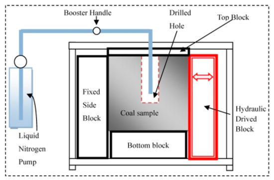
Figure 1.
Schematic diagram of the custom-designed experimental device for liquid nitrogen injection and confining pressure application.
A liquid nitrogen pump was used to slowly inject liquid nitrogen into the hole of coal samples for 4 h and then the coal samples were placed at room temperature for 20 h. That process was called 1 cycle of cold loading. Liquid nitrogen was injected for 3 cycles. The overall surface morphology of the coal sample before and after the experiment was observed with a 10× zoom camera (Eos80d, Canon, Tokyo, Japan). The width of the cracks on the surface of the coal sample before and after the experiment was observed by an inverted metallographic microscope (Axiovert 40 MAT, Carl Zeiss AG, Jena, Germany). The observation area is a circle with a diameter of 5 mm, the observation direction was fixed so that the fissure width can be measured and compared with the different samples. A nonmetallic ultrasonic detecting and analysis instrument (NM-4A, Koncrete, Beijing, China) was used to measure the propagation velocities (vx, vy, vz) of sound waves in the coal sample before and after the experiment, and the change of porosity of the coal sample was analyzed according to Wyllie’s time average equation [13]. The uniaxial compression experiment was carried out by an MH-25 experimental machine to measure the uniaxial compressive strength of the coal sample after the experiment to qualitatively analyze the structural damage degree of the coal sample. The specific experimental process is shown in Figure 2.
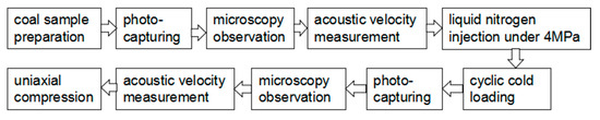
Figure 2.
Flow chart of experiments.
3. Results and Discussion
3.1. Experimental Results
3.1.1. Surface Fracture Morphology
Three cycles of liquid nitrogen injection were carried out under confining pressures from 0 MPa to 7 MPa to coal samples. Surface fracture topography of the coal samples before and after the experiment was detected by an inverted metallographic microscope, shown in Figure 3. The width of cracks (fissure width) in the corresponding positions on the surface of the coal samples was recorded and shown in Table 2. A, B, and C marked in Figure 3 were the determination spots of fissure width, and the corresponding obtained results were shown in Table 2.
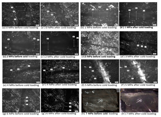
Figure 3.
Surface fracture topography of coal samples under varied confining pressures after three periods of liquid nitrogen injection.
Table 2.
Fissure widths of coal samples under varied confining pressures after 3 cycles of liquid nitrogen cold loading.
In Table 2, d0 was the fissure width of the coal sample before cold loading and dn was the fissure width of the coal sample after n cycles of cold loading. The Bessel method was applied to calculate the standard deviation of fissure width data. Before cold loading, the standard deviation was 75.37 μm, 163.66 μm, 50.90 μm, 2.12 μm, 22.32 μm, 66.71 μm, and 21.27 μm, respectively for coal samples under confining pressure of 0 MPa to 6 MPa. After cold loading, the relevant data changed to 67.30 μm, 121.13 μm, 54.02 μm, 5.68 μm, 23.59 μm 69.98 μm, and 8.56 μm, respectively. The coal samples under 7 MPa confining pressure broke after 3 cycles of liquid nitrogen injection cold loading, so the fissure width could not be measured.
According to Table 2, the resultant expansion of fissure width versus confining pressure was presented and fitted in Figure 4. Equation (1) was derived from the fitted curve of Figure 4.
where ∆d is the increment of crack width on the surface of the coal sample (µm); σ3 is the confining pressure (MPa). The values of a and b were shown in Table 3.
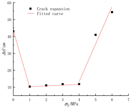
Figure 4.
Curve of fracture width vs. confining pressure of coal samples after a 3-cycle liquid nitrogen injection.
Table 3.
Values of parameters a and b in Equation (1).
As shown in Figure 4, when free of confining pressure, the fissure width value was between values of 5 MPa and 6 MPa. From 1 MPa to 4 MPa of applied confining pressure, fissure width increased with the increase of confining pressure, but the growth slope was low. Meanwhile, in Table 2, at point B of 1 MPa and point C of 2 MPa, those fissure widths decreased after cold loading, indicating the irregularity of fracture damage of the coal sample was caused by its heterogeneity. With the increase of confining pressure, the fissure expansion on the surface of the coal sample decreased first and then increased. When confining pressure increased from 4 MPa to 6 MPa, the fissure width increased rapidly.
Permeability measurement of coal samples before and after the cold loading test showed that the coalbed methane permeability increased from 0.494 × 10⁻⁴ μm2 to 1.03 × 10⁻³ μm2, which was greater than the limit of low permeability (0.1 × 10⁻³ μm2). That means coalbed methane can be smoothly extracted to achieve efficient exploitation.
3.1.2. Determination of Damage Degree of Overall Structure of Coal Sample
After 3 cycles of cold loading with liquid nitrogen injection, the airwave velocity attenuation rate (coded as WVA rate) in the confining pressure coal sample from 0 to 7 MPa was calculated according to Equation (2) and the results were shown in Table 4. The relationship between WVA rate and confining pressure was shown in Figure 5.
where η is the WVA rate; vn is the propagation velocity of the sound wave in the coal samples after n cycles of liquid nitrogen injection, (m/s), v0 is the propagation velocity of the sound wave in the coal sample before injecting liquid nitrogen (m/s).
Table 4.
WVA rates of coal samples under varied confining pressures after three periods of liquid nitrogen injection.
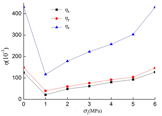
Figure 5.
The curve of the airwave velocity attenuation (WVA) rate and confining pressure.
It can be seen from Figure 5 that the WVA rate decreased first and then increased with the increase of confining pressure. According to Wyllie’s time-averaged equations [30], it can be deduced that the porosity of the coal sample had a relationship with the WVA rate as Equation (3):
where vt is the propagation velocity of the sound wave in water (m/s), vma is the propagation velocity of the sound wave in the coal material (m/s), v0 is the initial propagation velocity of the sound wave in the coal sample(m/s), η is the WVA rate of the wave velocity and ø is porosity of the coal sample.
Since vma, vm, and vt are fixed values in the same coal sample, porosity ø is a linear function of η. The larger the WVA rate, the larger the porosity of coal samples. The WVA rate of the 0 MPa and 6 MPa confining pressure coal samples was significantly high, indicating that the structural damage degree of the coal samples was very large. When the initial wave velocity v0 was 1479 m/s, the vma was 2168.44 m/s and vt was 1497 m/s, the pore volumes of the 0–6 MPa confining pressure coal sample were obtained as 3.53%, 1.47%, 1.75%, 1.98%, 2.17%, 2.46%, and 3.51%, respectively. The pore sizes of the coal sample decreased first and then increased with the increase of confining pressure.
3.1.3. Uniaxial Compressive Strength of Coal Sample after Cyclic Cold Loading
After cold loading for 3 cycles with liquid nitrogen injection, the uniaxial compression experiment of the coal sample was conducted at a loading rate of 0.1 mm/min by MH-25 experimental equipment at room temperature. The stress-strain curve of uniaxial compression of the coal sample was shown in Figure 6.
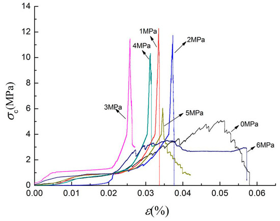
Figure 6.
Stress-strain curve of coal samples under varied confining pressure after 3 cycles of liquid nitrogen injection.
As can be seen from Figure 6, the uniaxial compressive strength of coal samples after 3 cycles of liquid nitrogen injection under confining pressures from 0 MPa to 6 MPa was 5.1 MPa, 12.3 MPa, 11.7 MPa, 11.4 MPa, 10.3 MPa, 6.0 MPa, and 3.5 MPa, respectively. The peak value of the uniaxial compressive strength curve represents the maximum bearing capacity of the coal sample, which is an important mechanical parameter for coal material. A higher peak value represents a better mechanical property of a tested coal sample and smaller structural damage. A lower peak value represents a more serious deterioration of mechanical properties and larger structural damage. It can be seen that the compressive strength of the coal sample of 0 MPa was relatively low, and the uniaxial compressive strength of the coal sample with confining pressure decreased with the increase of confining pressure. The peak values of curves versus the corresponding confining pressures were presented and fitted in Figure 7 and Equation (4):
where σc is the uniaxial compressive strength (MPa), σ3 is the confining pressure (MPa), and the values of a and b were shown in Table 5.
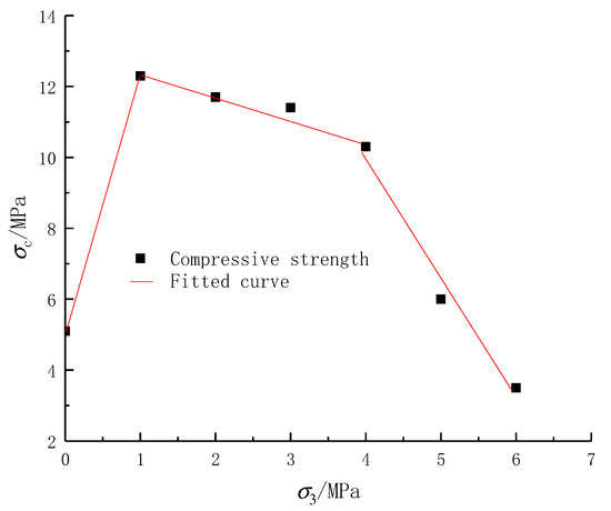
Figure 7.
Compressive strength vs. confining pressure of coal samples under varied confining pressures after 3 cycles of liquid nitrogen injection.
Table 5.
Values of parameters a and b in the Equation (4).
The 7 MPa confining pressure coal sample was crushed and lost its bearing capacity after 3 cycles of liquid nitrogen injection. The uniaxial compressive strength of the sample under 0 MPa differed little from that of the sample under 0 MPa, indicating that the damage degree of the two coal samples was basically the same. With the increase of confining pressure, the uniaxial compressive strength of the coal sample decreased. Low confining pressure had an inhibitory effect on the structural damage of coal samples.
The relationship of uniaxial compressive strength, fissure width, and confining pressure of the coal sample were presented in Figure 8 and Equation (5).
where σc is the uniaxial compressive strength (MPa) of the coal sample, Δd is the fissure width (μm) and σ3 is the confining pressure (MPa). The fitting degree was 96.721%.
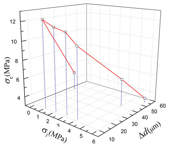
Figure 8.
The relationship of uniaxial compressive strength, fissure width, and confining pressure of the coal sample under varied confining pressures after three cycles of liquid nitrogen injection.
The relationship of uniaxial compressive strength, fissure width, and confining pressure of the coal sample were presented in Figure 8 and Equation (5). If two parameters (fissure width and confining pressure of one coal sample, etc.) were provided, the third parameter (uniaxial compressive strength, etc.) could be derived. The curve in Figure 8 was the numerical figure for determining the permeability of coal and rock fractures in the process of coalbed methane exploitation. The Griffith strength theory believes that the fracture of brittle materials under external force is the result of the continuous development of internal cracks [31]. In the process of cold loading, when the expansion of pores and fissures of the coal body reached the damage strength, the pore and fissure structure of the coal sample developed from micro to macro and resulted in accumulated damage. When the compressive strength of the coal sample was reached, the coal sample lost its bearing capacity.
3.2. Theoretical Analysis
3.2.1. Influence of Temperature Stress on Structural Damage of Coal Sample
When liquid nitrogen was injected into the coal sample, the temperature inside the coal sample dropped suddenly and temperature stress and temperature strain would be generated. Coal has the property of thermal expansion and contraction as a solid medium. Meanwhile, the coal matrix is a composite. The contraction volume during cold loading can be varied by locations as the composition of coal material may be different in different places. Thus, the strain of each component is different. When the maximum linear strain caused by the cold contraction of the coal sample reaches the limit of the linear strain of the coal sample, the tensile fracture will be caused to the pore and fracture structure of the coal sample.
The coal matrix was divided into different units, and the temperature variation for each unit is coded as Δt. It is assumed that there was a tiny unit near the crack of the coal sample which was homogeneous. Under the action of temperature stress σt, the strain εz in z direction should satisfy the thermoelastic mechanical Equation (6) [32].
where, εz is the linear strain in the z direction—vertical to the stratification plane, α is linear expansion coefficient (1/°C), σz is the normal stress in z direction and ν is Poisson’s ratio. When the constant εz of a unit is greater than the linear strain limit, local structural damage occurs. The correspondent temperature stress is as Equation (7):
where σt represents temperature stress (MPa), α is the linear expansion coefficient (1/°C) and E is the modulus of deformation (GPa).
Under standard atmospheric pressure, the gasification temperature of liquid nitrogen is −195.8 °C. By experiencing liquid nitrogen injection, the temperature of the coal sample was reduced abruptly. In that case, Δt value was 216 °C, E value was 3.2 GPa and α was 6.435 × 10⁻⁶/°C. The resultant internal temperature stress σt of the coal sample should be 4.45 MPa, which was greater than the tensile strength of the coal sample matrix −0.52 MPa. Thus, the pore and fracture structure of the coal sample was damaged or even broken. Eventually, the size of pores and fissures of the coal sample increased.
3.2.2. The Influence of Confining Pressure on Structural Damage of Coal Sample
The horizontal maximum principal stress σH and the horizontal minimum principal stress σh of the coal samples originated from horizontal confining pressure applied by the hydraulic side blocks. The displacement of the coal sample was constrained by the top and bottom plates, which produced vertical stress σv. As the coal sample was subjected to normal stresses (compression) in three directions, it can be simplified as Equations (8) and (9):
The main stresses subjected to the coal sample were confining pressure and temperature stress. In the test, the confining pressures in horizontal direction were the same, so the horizontal confining pressures were defined as σc. The confining pressure device only acts as a constraint in the vertical direction of the coal sample, which is negligible. At the same time, during the process of liquid nitrogen injection, the temperature stress σt existed in all directions inside the coal sample, but the temperature stress σt parallel to the direction of the fracture had little influence on the expansion of the fracture, which was omitted in the process of simplifying the numerical model in this study. Horizontal principal stress is caused by tectonic movement and is related to vertical stress, tectonic stress, pore fluid pressure, temperature, and mechanical characteristics of the coal sample. According to Ge’s model [33], the influence of temperature on the confining pressure can be considered independently. Thus, the confining pressure calculating formulation that takes temperature stress into account can be obtained as Equation (10) [34]:
where ζH and ζh are the tectonic stress coefficient in the direction of the maximum and minimum horizontal principal stresses, αt is the pore elasticity coefficient, PP is the pore fluid pressure (MPa), ν is Poisson’s ratio, E is elastic modulus of the coal sample (GPa) and Δt is the temperature variation(°C).
In this study, Young’s modulus and Poisson’s ratio were not considered as the function of temperature, the vertical stress was assumed to be constant, and the influence of pore elasticity coefficient, tectonic stress coefficient, and pore fluid pressure was ignored. Then the calculation formula of horizontal stress considering the expansion stress caused by temperature is obtained:
when the injection process of liquid nitrogen was finished, the temperature of the coal sample gradually returned to room temperature, so the original mechanical parameters of the coal sample, such as Young’s modulus E and Poisson’s ratio ν would change. Suppose E’ and ν’ are the mechanical parameters of the coal sample after injecting liquid nitrogen, the confining pressure formula of the coal sample after cold loading can be obtained according to Equation (11), as shown in Equation (12).
After the injection of liquid nitrogen, the coupled action of temperature stress and confining pressure would generate stress which exceeded the strength limit of the coal sample. That was the reason for pore and fracture structural damage of the coal sample. The relationship between the load-induced structural damage and stratification direction of coal samples can be analyzed by using the Mohr-Coulomb strength theory [22], as shown in Equation (13):
where θ is the angle between stratification and horizontal principal stress (°), τ1 is the shear strength limit (MPa), and c0 is the cohesive stress (MPa).
The shear stress acting on the stratification direction can be solved as:
when θ is equal to zero, Equation (14) can be simplified as:
when Equation (16) was satisfied, the fissure structure of the coal sample would be damaged and easy to crack along the stratification direction, which indicates that the fracture structure size of the coal sample would expand rapidly in the vertical direction of stratification.
In summary, coal samples with drilled holes suffered larger confining pressure in the direction parallel to stratification. There was room for strain in the horizontal direction, but the strain in the vertical direction of stratification was smaller. Stress concentrated on the inner wall plane of the drilled holes. Under the combined effect of thermal stress and confining pressure, once the strength limit of the pore structure was reached, localized damage appeared. After cyclic cold loading, damage accumulated and macro fracture emerged when the strength limit was exceeded. With the increase of confining pressure, the strain increment in the vertical direction of stratification would be enlarged and the damage would be more and more serious until the coal samples were destroyed.
Results show that in the process of coalbed methane exploitation, drilling vertical injection holes in the coalbed methane reservoir, and carrying out cold loading for 3 cycles can effectively increase the fracture size of the coalbed methane reservoir and improve the exploration efficiency of coalbed methane.
3.2.3. Numerical Model
The original coal sample has pores, cracks, and initial defects. Under the action of multiple cyclic liquid nitrogen cold loading, these initial pore and fracture structures would experience damage, expansion, and interconnection, which would bring in macroscopic cracks and final destruction of the coal body. This is the process of joint size evolution from microscopic to macroscopic of the coal sample. Considering the coupling effect of temperature stress, confining pressure during cyclic liquid nitrogen cold loading, the numerical model of fissure expansion of the coal sample was constructed by finite element analysis software, ANSYS (15.0, ANSYS Inc, Canonsburg, PA USA). The size of the model element was specified as 100 mm × 100 mm × 100 mm. The temperature stress σt caused by cold loading of liquid nitrogen was 4.45 MPa. The direction of temperature stress σt was set to be vertical to the direction of the crack, and the confining pressure is set as the plane uniform load for 0 MPa, 1 MPa, 2 MPa, 3 MPa, 4 MPa, 5 MPa, 6 MPa, and 7 MPa, respectively. The numerical model of the coal sample under cold loading of cyclic liquid nitrogen was shown in Figure 9 and the numerical simulation result of fissure expansion damage of coal sample was shown in Figure 10. The simulation model of Figure 9 was the numerical verification of Section 3.1, which theoretically analyzed and verified the high matching degree of the experiment and theoretical analysis.
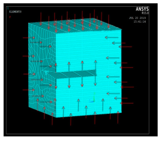
Figure 9.
Mechanical model of cold loading of the coal sample with circulating liquid nitrogen.
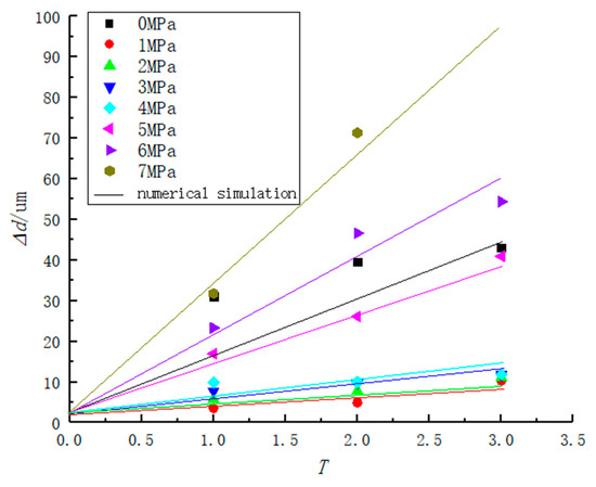
Figure 10.
Numerical simulation results of fissure expansion vs. cycle number (Lines for simulation data and spots for experimental data).
After the finite element modeling, the fissure structure and loaded form of the coal sample were simulated and analyzed. The structural damage process of the coal sample was also numerically simulated, which can accurately reveal the structural damage degree and fracture law of the coal sample under different conditions. In Figure 10, straight lines were theoretically simulated data and spots were experimental data of fissure expansion of coal samples. Numerical results were basically consistent with experimental results, indicating that the theoretical analysis was rational. According to numerical analysis, the relationship between fissure width expansion and time under various confining pressures can be considered as approximately linear, indicating that the structural damage evolution process was nearly linear. Those results can provide a theoretical research basis for the coal samples cold loaded by liquid nitrogen in the application of coalbed methane mining improvement.
4. Conclusions
(1) Experimental research shows that the structural damage of pore and fissure in coal samples with drilled holes increases with the increase of confining pressure. The maximum fissure width expansion was 54.39 μm. After three cycles of cold loading under the 7 MPa confining pressure, the damage expansion of pore and fissure accumulates to exceed the strength limit of coal samples and thus the coal sample experienced complete fracture.
(2) In the test, temperature stress induces stress concentration at the end of fissures so that fissures propagate along the direction of stratification. For coal samples with original fissures, the tested fissure widths generally increased as the increase of confining pressure, and the maximum pore volume was 3.51%. For those without original fissures, the pore volume was 3.53%. It is illustrated that cold loading of liquid nitrogen plays an outstanding role in permeability improvement of coal samples in the way of structural damage.
(3) The numerical model and damage criterion of the coal sample under the influence of liquid nitrogen cold loading were established. The numerical model was constructed to simulate the damage expansion of the coal sample surface crack, in which the theoretical value matched the experimental result well. Damage criterion showed that when the practical stress of coal samples exceeds its cohesive stress (τ ≥ c0), damage occurs. Thus, under the coupling effect of both the temperature stress sourcing from cold loading of liquid nitrogen and the confining pressure, the structural damage limit can be reached to efficiently improve the permeability of the coal seam and to promote the efficient exploration of coalbed methane. Meanwhile, environmental pollution caused by coalbed methane discharged can be effectively prevented.
Author Contributions
Conceptualization, H.L.; data curation, X.X.; formal analysis, X.X.; funding acquisition, J.Z.; investigation, H.L.; methodology, H.L.; project administration, H.L., L.W., and P.L.; resources, L.W.; software, X.X.; supervision, H.L. and J.Z.; visualization, X.X.; writing—original draft, H.L.; writing—review and editing, P.L. All authors have read and agreed to the published version of the manuscript.
Funding
This research was funded by the National Natural Science Foundation of China, grant number 51704142 and 51905246”, Project of Liaoning doctoral research initiation fund, grant number 2019-BS-115 and Natural Science Foundation of Liaoning Province, grant number 20170540415.
Acknowledgments
The authors want to show our appreciation to the State Key Laboratory of Coal Resources and Safe Mining (CUMT) of China University of Mining and Technology for their experimental and material supports.
Conflicts of Interest
The authors declare no conflict of interest.
References
- Mark, Z.J.; Mark, A.; Delucchi, M.A.; Cameron, S.J.; Coughlin, C.A.; Hay, I.P.; Manogaran, Y.; Shu, A.K.K. Impacts of Green New Deal Energy Plans on Grid Stability, Costs, Jobs, Health, and Climate in 143 Countrie. One Earth 2019, 1, 449–463. [Google Scholar]
- Saptorshee, K.C.; Massimiliano, M. Energy intensity and green energy innovation: Checking heterogeneous country effects in the OECD. Struct. Chang. Econ. Dyn. 2020, 52, 328–343. [Google Scholar]
- Ishaq, H.; Dincer, I. A comparative evaluation of OTEC, solar and wind energy based systems for clean hydrogen production. J. Clean. Prod. 2019, 11, 8736. [Google Scholar] [CrossRef]
- Wagner, A.O.; Lackner, N.; Mutschlechner, M.; Prem, E.M.; Markt, R.; Illmer, P. Biological Pretreatment Strategies for Second-Generation Lignocellulosic Resources to Enhance Biogas Production. Energies 2018, 11, 1797. [Google Scholar] [CrossRef] [PubMed]
- Wayne, N. Clean, Safe Nuclear Power? Drillers Have a Role. Natl. Driller 2019, 40, 6. [Google Scholar]
- Siddiqui, O.; Dincer, I.; Yilbas, B.S. Development of a novel renewable energy system integrated with biomass gasification combined cycle for cleaner production purposes. J. Clean. Prod. 2019, 241, 18345. [Google Scholar] [CrossRef]
- Ajay, K.; Singh, J.K. Fugitive Methane Emissions from Indian Coal Mining and Handling Activities: Estimates, Mitigation and Opportunities for its Utilization to Generate Clean Energy. Energy Procedia 2016, 90, 336–348. [Google Scholar]
- Hu, Q.T.; Liang, Y.P.; Wang, H.; Zou, Q.L.; Sun, H.T. Intelligent and integrated techniques for coalbed methane (CBM) recovery and reduction of greenhouse gas emission. Environ. Sci. Pollut. Res. Int. 2017, 24, 17651–17668. [Google Scholar]
- Tutak, M.; Brodny, J. Forecasting Methane Emissions from Hard Coal Mines Including the Methane Drainage Process. Energies 2019, 12, 3840. [Google Scholar] [CrossRef]
- Moore, T.A. Coalbed methane: A review. Int. J. Coal Geol. 2012, 101, 36–81. [Google Scholar] [CrossRef]
- Cao, D.L. Monte-Carlo simulation of seepage in fractured rock mass. J. CRSRI 1989, 3, 55–61. [Google Scholar]
- Zhang, Z.Q.; Zhao, H.C.; Zhang, X.L. Study on AR Technology of Low Permeability Coal-bed Methane Reservoirs by Freezing and Thawing Cycles. Coal Technol. 2015, 34, 144–146. [Google Scholar]
- Maxim, C.; Andrey, C. Evaluating characteristics of high-rate hydraulic fractures driven by wellbore energy source. Eng. Fract. Mech. 2019, 10, 6702. [Google Scholar]
- Robin, L.; Franck, V.; Nicolas, A.; Hervé, L.P.; Jean, L.P.; Li, H.; Paul, T.; Marie-Luce, C.; Stephane, G.; Gweltaz, M.; et al. Reply to Comment on “Large-scale geometry, offset and kinematic evolution of the Karakorum fault, Tibet”. Earth Planet. Sci. Lett. 2004, 1, 159–163. [Google Scholar]
- Chen, S.L.; Huang, B.X.; Xu, J. Experimental Study of Basic Law of High Pressure Water Jet Punching. Coal Min. Technol. 2017, 4, 38. [Google Scholar]
- Lin, B.Q.; Shen, C.M. Coal permeability-improving mechanism of multilevel slotting by water jet and application in coal mine gas extraction. Environ. Earth Sci. 2015, 10, 5975–5986. [Google Scholar] [CrossRef]
- Li, H.L. The Composite Perforating Dynamic Testing Technology Research of Coal-bed Gas Well. Master’s Thesis, North University of China, Taiyuan, China, 2013. [Google Scholar]
- Yuan, W.; Liu, S.; Wang, W.; Su, X.; Li, Z.; Li, J.; Wen, L.; Chang, J.; Sun, X. Numerical study on the fracturing mechanism of shock wave interactions between two adjacent blast holes in deep rock blasting. Earthq. Eng. Eng. Vib. 2019, 18, 735–746. [Google Scholar] [CrossRef]
- Tran, D.; Settari, A.; Nghiem, L. Initiation and Propagation of Secondary Cracks in Thermo-Poro elastic Media. In Proceedings of the 46th US Rock Mechanics/Geomechanics Symposium, Chicago, IL, USA, 24–27 June 2012. [Google Scholar]
- Li, J.Z. The enlightenment on the construction of urban infrastructure in China from Dujiangyan Irrigation Project. In Proceedings of the Abstracts of International Conference on Civil, Architectural, Structural and Constructional Engineering, Busan, Korean, 15–17 July 2016. [Google Scholar]
- Ren, S.R.; Fan, Z.K.; Zhang, L.; Yang, Y.; Luo, J.; Che, H. Mechanisms and experimental study of thermal-shock effect on coal-rock using liquid nitrogen. J. Rock Mech. Eng. 2013, S2, 3790–3794. [Google Scholar]
- Cai, C.-Z.; Li, G.-S.; Huang, Z.-W.; Shen, Z.-H.; Wang, H.-Z.; Tian, S.-C.; Wei, J.-W. Experiment study of rock porous structure damage under cryogenic nitrogen freezing. Rock Soil Mech. 2014, 4, 965–971. [Google Scholar]
- Zhang, C.H.; Zhao, Q.S.; Wang, L.G.; Zhao, Q.S.; Li, W.L. Permeability evolution model and numerical analysis of coupled coal deformation, failure and liquid nitrogen cooling. J. Hebei Univ. Sci. Technol. 2015, 36, 90–99. [Google Scholar]
- Grundmann, S.R.; Rodvelt, G.D.; Dials, G.A.; Allen, R.E. Cryogdnics nitrogen as a hydraulic fracture fluid in the devonian shale. In Proceedings of the SPE Eastern Regional Conference, Pittsburgh, PA, USA, 9–11 November 1998. [Google Scholar]
- Coetzee, S.S.; Neomagus, H.W.J.P.; Bunt, J.R.; Strydom, C.A.; Schobert, H.H. The transient swelling behavior of large (−20+16mm) South African coal particles during low-temperature devolatilisation. Fuel 2014, 136, 79–88. [Google Scholar] [CrossRef]
- Li, H.W.; Wang, L.G.; Zhang, C.H.; Zhang, H.; Zhou, H.; Geng, Y.Y. Investigation on damage laws of loading coal samples under cyclic cooling treatment. J. China Coal Soc. 2017, 9, 2345–2352. [Google Scholar]
- Li, H.W.; Wang, L.G.; Niu, F.M.; Liu, W.F.; Zhang, C.H. Study on effect of freeze-thaw cycle with liquid nitrogen on crack extension of coal at different initial temperatures. China Saf. Sci. J. 2015, 10, 121–126. [Google Scholar]
- Zhang, C.H.; Guo, X.K.; Li, H.W.; Zhao, N.; Wang, L.G. Study on influence of liquid nitrogen infiltration to saturated water coal fracture expanded. Coal Sci. Technol. 2016, 6, 99–105. [Google Scholar]
- Cai, C.Z.; Li, G.S.; Huang, Z.W. Experiment of coal damage due to super-cooling with liquid nitrogen. J. Nat. Gas Sci. Eng. 2015, 22, 42–48. [Google Scholar] [CrossRef]
- Shi, G.; Shen, L.D. Evaluations of the lithological character and physical property of rocks from the relation between wave velocity and pressure-an experimental study. Chin. J. Geophys. 1990, 2, 212–218. [Google Scholar]
- Makhutov, N.A.; Matvienko, Y.G. Griffith theory and development of fracture mechanics criteria. Mater. Sci. 1993, 3, 115–123. [Google Scholar] [CrossRef]
- Finnie, I.; Cooper, G.; Berlie, J. Fracture propagation in rock by transient cooling. Int. J. Rock Mech. Min. Sci. Géoméch. Abstr. 1979, 16, 11–21. [Google Scholar] [CrossRef]
- Zhang, Y.P. Study on Liquid Nitrogen Fracturing Technology in Coalbed Methane Well. Ph.D. Thesis, Southwest Petroleum University, Chengdu, China, 2015. [Google Scholar]
- Li, H.W.; Wang, L.G.; Zhang, C.H.; Zhang, H.; Zhou, H.; Su, R.H. Structural damage mechanism for cold loaded coal samples under different confining pressures. Chin. J. Appl. Mech. 2017, 04, 788–794+823. [Google Scholar]


© 2020 by the authors. Licensee MDPI, Basel, Switzerland. This article is an open access article distributed under the terms and conditions of the Creative Commons Attribution (CC BY) license (http://creativecommons.org/licenses/by/4.0/).