Article

Reliability Assessment of a Fault-Tolerant PV Multistring Inverter

by
Hugues Renaudineau
1,
Pol Paradell-Solà
2,*,
Lluís Trilla
2,
Alber Filba-Martinez
2,
David Cardoner
3 and
José Luis Domínguez-García
2
1
Electronics Engineering Department, Universidad Técnica Federico Santa María, Valparaíso 2390123, Chile
2
Institut de Recerca en Energia de Catalunya, 08930 Barcelona, Spain
3
Technology Centre of Catalonia Eurecat, 08005 Barcelona, Spain
*
Author to whom correspondence should be addressed.
Energies 2020, 13(24), 6525; https://doi.org/10.3390/en13246525
Submission received: 30 October 2020 / Revised: 3 December 2020 / Accepted: 5 December 2020 / Published: 10 December 2020
(This article belongs to the Special Issue Smart Photovoltaic Energy Systems for a Sustainable Future)

Abstract

:
In photovoltaic (PV) systems, the reliability of the system components, especially the power converters, is a major concern in obtaining cost effective solutions. In order to guarantee service continuity in the case of failure of elements of the PV converter, in particular, semiconductor switching devices, a solution is to design power converter with fault-tolerance capability. This can be realized by aggregating hardware redundancy on an existing converter, providing the possibility of replacement of faulty elements. This paper evaluates the reliability of a fault-tolerant power electronics converter for PV multistring application. The considered fault-tolerant design includes a single redundant switching leg, which is used in order to reconfigure the structure in case of a switch failure either on DC-AC or DC-DC stages. This paper details the reliability estimation of the considered PV multistring fault-tolerant converter. Furthermore, a comparison with a conventional structure without fault-tolerant capability is provided. The results show that the introduction of a single redundant leg allows for improving the converter mean time to failure by a factor of almost two and it reduces, by half, the power loss due to system-failure shutdowns in PV applications, while only increasing the converter cost by 2–3%.

1. Introduction

System reliability is one of the key parameters for obtaining cost-effective and sustainable solutions in the photovoltaic (PV) system. Indeed, an unexpected shutdown due to system components failure can cause significant production loss [1]. In PV applications, the weakest elements with the higher failure rate are the power electronic converters [2]. In this regard, the power inverter is responsible for approximately 50% of the total failures on a PV plant [3,4], whch means an impact on the average power loss of more than 35% [3,5] with a larger impact when considering central-inverter solutions. Therefore, designing a more reliable power electronic converter is very important. One way to improve the converter reliability is to design a fault-tolerant solution that is able to maintain operation in the case of a failure of elements of the converter [2].
Capacitors, printed-circuit boards, and semiconductor switching devices are the weakest elements of power electronic systems [2]. The failure of insulated-gate bipolar transistors (IGBTs) in power electronics converters is then of major importance and it has been largely studied, such as in [6,7], where the existing methods to handle the failure and achieve fault-tolerant operation are also reviewed. Faults that occur on the switching devices can be classified into short- and open-circuit faults [8]. Short-circuit fault results in a short-circuit at the DC-link capacitor and it would lead to a shut down of the system. However, short-circuit can be detected by the switch control driver and it has become a standard feature of commercial drivers in order to prevent a shoot-through fault during short-circuit faults by suppressing the switching control drive signals to the healthy switching device on the same leg [8]. Short-circuit faults then result in an open-circuit on the leg. On the other hand, open-circuit faults cannot be detected by the driver, and an additional circuit is required in order to obtain open-circuit fault-tolerant operation [9].
Many fault-tolerant techniques have been proposed in the literature, as reviewed in [10]. Fault-tolerant solutions are always based on hardware redundancy and associated control strategies [10]. They can be classified between switch-level, leg-level, module-level, and system-level solutions, depending on the type of hardware redundancy [10], with the redundant-leg topology being considered to be the optimal compromise between system cost, performance, and reliability [10]. Leg-redundant fault-tolerant solutions have been largely proposed in the case of three-phase inverters [11,12] and single-phase DC-AC converters [13]. Other studies have focused on leg-redundant fault-tolerant operation of DC-DC converters, such as [14,15]. In [16], fault detection and identification for both DC-DC and DC-AC converters are proposed, but without fault-tolerant operation.
In this paper, a fault-tolerant PV multistring inverter is proposed. It consists of a conventional two-stage DC-AC PV multistring converter with the introduction of a single redundant switching leg. The redundant leg can be used for reconfiguring the system and replacing a faulty leg, either on the DC-DC and DC-AC converter stages. The proposed converter can then continue operating in case of failure of one switching device of the system. This paper provides a reliability assessment of the proposed converter and compares it with the conventional non-redundant converter, in order to quantify the interest of introducing one additional leg.
This paper is organized as follows. First, Section 2 describes the proposed fault-tolerant PV multistring inverter and its principle of operation, calculates the converter component failure rates, and then obtains the reliability model of the converter. Section 3 provides the methodology that was followed to perform the simulation of the proposed fault-tolerant system. In order to verify the converter feasibility, Section 4 presents the simulation results of the converter switching model under different faulty switches. It also presents the converter reliability results that were obtained from the reliability model and compares them with the reliability of the conventional non-fault-tolerant topology. A thorough discussion of the results is provided. Section 5 provides a view on the economic aspects of the proposed fault-tolerant converter and its impact on PV applications. Finally, Section 6 provides some conclusions of this work.

2. Theory

This section describes the structure and principle of operation of the proposed fault-tolerant PV multistring inverter, as well as the reliability model of the converter components and the overall system, which allows for computing the estimated reliability of the converter.

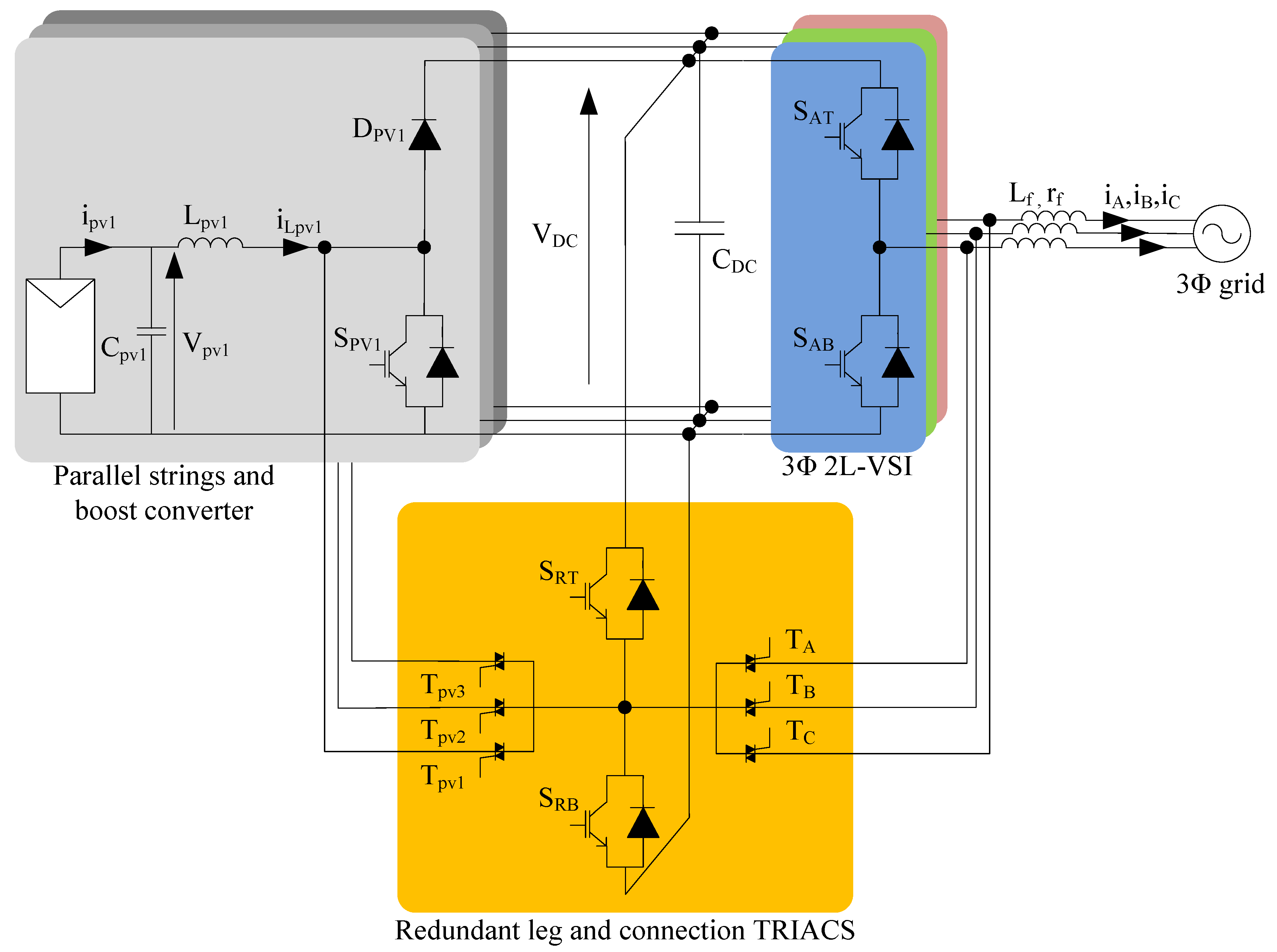
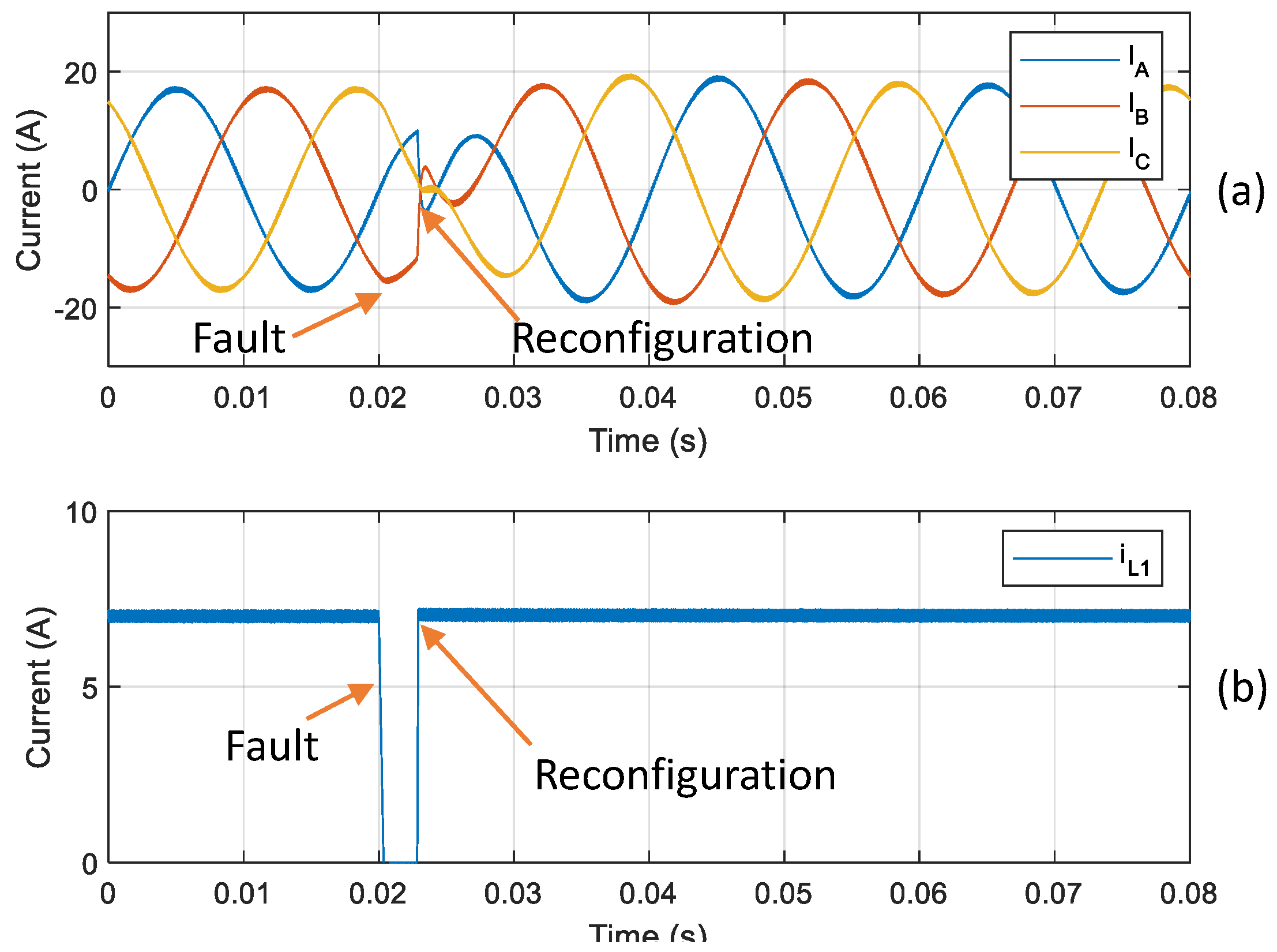
2.1. Fault-Tolerant Converter

Figure 1 shows the considered fault-tolerant PV multistring inverter. It consists of two stages. The first stage is constituted by three DC-DC boost converters that are connected to the PV strings and the second stage consists of a two-level three-phase DC-AC converter that is connected to the grid. The fault-tolerant part consists of a single redundant switching leg ( S RT , S RB , and its corresponding anti-parallel diodes) and six bidirectional triode thyristors (TRIACs, T pv 1 , T pv 2 , T pv 3 , T A , T B , and T C ) that connect the output of the redundant leg to the output of the DC-DC and DC-AC stages switching legs.
The converter fault-tolerant principle of operation consists of connecting the redundant leg in place of the faulty leg by enabling the TRIAC that is connected to the faulty leg. The described fault-tolerant mechanism is only valid when the switching devices fail in open circuit. Nonetheless, a switch short-circuit failure can be readily converted into an open-circuit failure by isolating the faulty device from the rest of the circuit. This can be done with fuses, TRIACs, or other appropriate devices (as the iFuse device described in [17]) by placing them in series, with each switch or at the switching-leg output. Therefore, the presented fault-tolerant mechanism can sustain switch open-circuit and short-circuit failures if proper measures are taken.
The switch open-circuit fault must be detected and localized in order to obtain fault-tolerant operation. Any fault detection and localization methods can be used with the proposed converter, provided that the detection, localization, and reconfiguration process is fast enough not to damage other parts of the system. For the DC-AC stage, possible fault detection and localization algorithm can be found in [18,19,20,21,22,23] and for the DC-DC stage it can be used, for example, the methods proposed in [14,15,24].
Nonetheless, in order to demonstrate the feasibility of the proposed fault-tolerant converter structure, specific fault-diagnosis methods are considered, which are later implemented in the converter model that is described in Section 3 in order to obtain the simulation results that are shown in Section 4. For instance, the switch open-circuit fault detection and localization functionalities on the DC-AC stage are implemented with the method that is proposed in [25]. This method is based on the current Park vector that was obtained from sensing the phase currents and allows detecting and localizing individual switch open-circuit faults in less than one fundamental period of the grid currents. It has been compared to other Park vector based approaches in [26], showing that one of its main advantages is the robustness of this diagnosis method. The switch open-circuit fault diagnosis on the DC-DC stage consists on sensing the inductor current and comparing it to a threshold value, empirically set to 2% of the nominal inductor current. Open-circuit fault is detected if the value of the current stays below this threshold for a number of samples higher than a threshold value (empirically set to 50). Fault detection is independent for each boost converter. Therefore, no localization algorithm is required. Both fault-diagnosis methods employ the existing current sensors that are required by the DC-DC and DC-AC stages controls, therefore offering a simple and economic method to perform the fault diagnosis.
Table 1 shows the number of elements and the references of the selected components for the proposed fault-tolerant converter. Table 2 shows the relevant converter parameters.

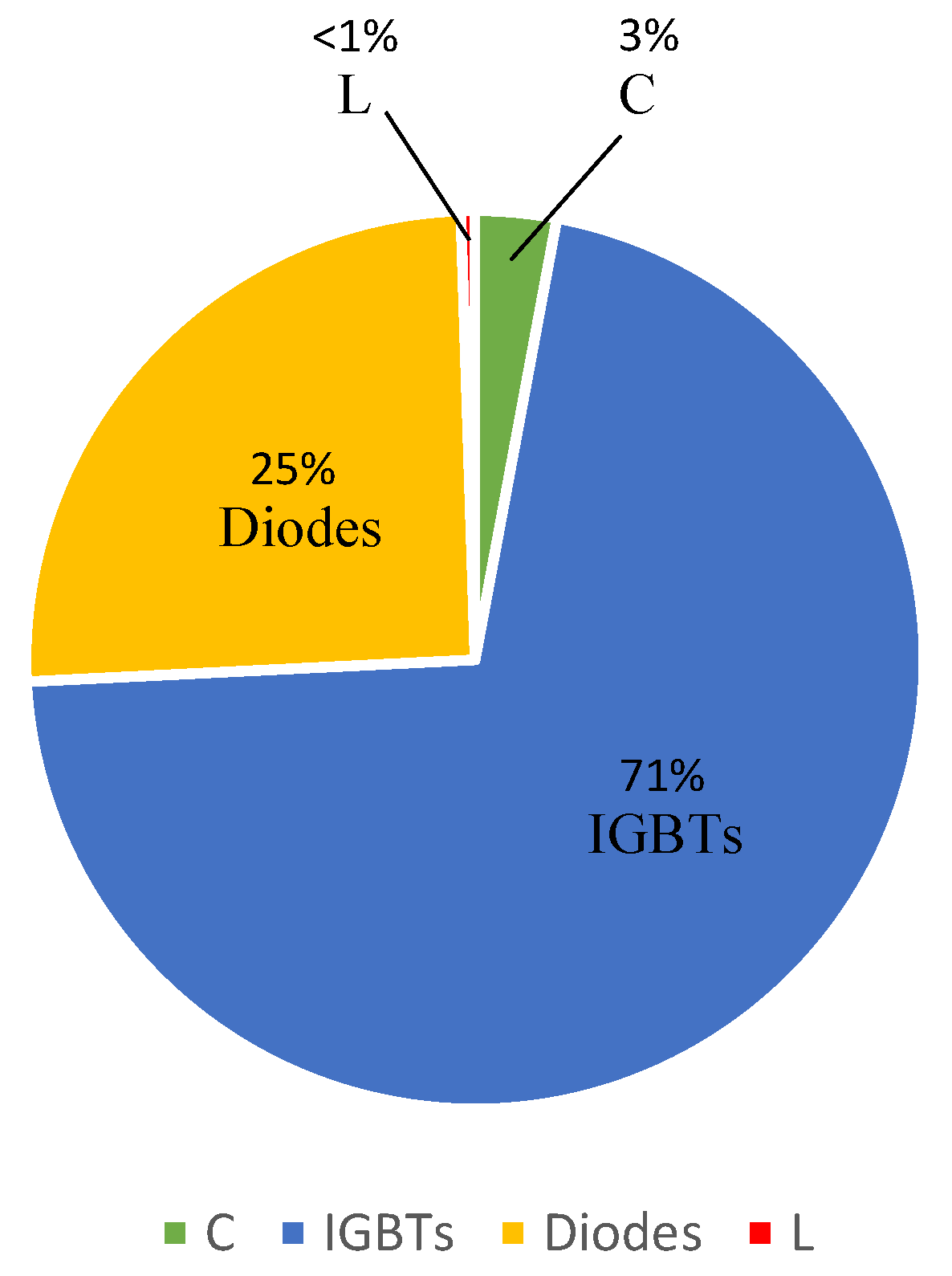
2.2. Component Failure Rates

In this paper, MIL-HDBK-217F [27] is used in order to obtain the component failure rates. Reference [27] is a commonly used standardization handbook that is employed for this purpose. It is often criticized to give pessimistic results and it has not been updated recently [28]. However, the aim of this paper is to prepare a framework for reliability comparison and assessment of the improvements that are achieved with the described fault-tolerant mechanism. Subsequently, any available data source can be adopted in the outlined procedure.
Table 3 presents the variables defining the component failure rates, whose units are in failures in time (FIT); i.e., failures per 10 6 h. These variables are defined in terms of a base failure rate ( λ b ) and a number of adjustments factors ( π ). The value of these parameters is dependent on the type of component, the component operating conditions, and its constructive parameters. For instance, λ I G B T 1 may be different to λ I G B T 2 , since the active IGBTs in the DC-DC stage may operate at different junction temperatures than those of the DC-AC stage. Appendix A provides the value of these parameters. It should be noted that the equations and parameter values defining the IGBT failure rates ( λ I G B T 1 and λ I G B T 2 ) do not appear in [27]. In order to overcome this, the same failure-rate model defined for the power metal-oxide-semiconductor field-effect transistor (MOSFET) will be considered, but with a λ b half of that of the MOSFET, as done in [28].
The failure rate of the redundant-leg devices is considered to be the same as the failure rate of the devices that they are substituting. For instance, when one of the DC-DC stage leg fails, the redundant-leg IGBT and diode failure rates will be equal to λ I G B T 1 and λ D 1 , respectively.
Figure 2 shows the relative contribution from each component to the multistring-inverter failure rate, calculated according to Table 1 and Appendix A. It can be noticed that the IGBTs and diodes are the most critical elements in terms of reliability. Therefore, the introduction of a redundant switching leg would be beneficial.

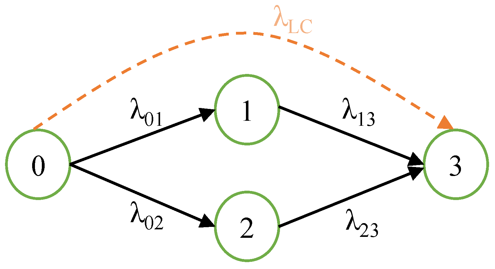
2.3. Reliability Model

Different approaches are typically applied in order to analyze the reliability of systems such as Monte Carlo or Markov chain reliability models [29,30]. For the present reliability assessment, a Markov chain reliability model is adopted, since it is an effective approach that can cover many features of redundant systems, such as sequence of failures, failure coverage, and state-dependent failure rates [29].
Two subsystems are considered in order to assess the reliability of the fault-tolerant PV multistring inverter. The first subsystem considers the critical faults that cannot be handled by the fault-tolerant system, i.e., capacitor and inductor failures. The second subsystem considers the fault-tolerant part of the converter (IGBTs, diodes, and TRIACs).
The first subsystem represents a trivial two-state Markov chain, which is represented in Figure 3 in dashed line. State 0 indicates that all the capacitors and inductors are working, while state 3 indicates that one or more of these devices has failed and the system is shut down. The reliability of the subsystem is
R 1 ( t ) = P ( t ) ,
where P ( t ) is the probability that all of the inductors and capacitors are operational. P ( t ) evolves over time according to
d P ( t ) d t = λ L C P ( t ) ,
where
λ L C = 12 λ C 1 + 3 λ L 1 + 20 λ C D C + 3 λ L 2
defines the compound failure rate of capacitors and inductors. In other words, as time progresses, the probability of all inductors and capacitors being operational decreases at a rate equal to λ L C P ( t ) , tending to zero when t .
The second subsystem is analyzed with a four-state Markov chain, which is illustrated in Figure 3 in solid lines. For its analysis, the reparation or degraded mode of operation of the converter is not considered; i.e., if one of the switching legs fails after the reconfiguration, the converter will cease its operation.
The states of the Markov chain are:
  • State 0: All of semiconductor devices are operational; redundant and connecting devices (TRIACs) are inactive.
  • State 1: One IGBT or diode on the DC-DC stage has failed; the redundant leg and corresponding TRIAC are activated.
  • State 2: One IGBT or diode on the DC-AC stage has failed; the redundant leg and corresponding TRIAC are activated.
  • State 3: A second IGBT or diode fails or the TRIAC activated in the previous states fails; the system shuts down.
The probability that the system is in the mth state at t moment is denoted as P m ( t ) . This probability evolves over time, according to
d P m ( t ) d t = m j λ m j P m ( t ) + j m λ j m P j ( t ) ,
that is, the probability of being in the mth state increases with the probability of its preceding states multiplied by the failure rates connecting it to those, and it diminishes with the probability of its succeeding states multiplied by the failure rates connecting it to those.
The state equation of the considered subsystem is given by
d d t P 0 ( t ) P 1 ( t ) P 2 ( t ) P 3 ( t ) = λ 01 λ 02 0 0 0 λ 01 λ 13 0 0 λ 02 0 λ 23 0 0 λ 13 λ 23 0 P 0 ( t ) P 1 ( t ) P 2 ( t ) P 3 ( t ) ,
where
λ 01 = 3 λ I G B T 1 + 3 λ D 1
λ 02 = 6 λ I G B T 2 + 6 λ D 2
  λ 13 = λ 01 + λ 02 + λ T 1
  λ 23 = λ 01 + λ 02 + λ T 2
are the failure rates that define the transitions between the Markov chain diagram states. In the definition of (8) and (9) it is considered that all of the converter switches (including the redundant-leg switches) are installed in the same heatsink. Therefore, when the redundant leg is enabled, the junction temperature of its devices will be equal to the prefault temperature of the devices that they are replacing. For this reason, λ 01 and λ 02 appear in (8) and (9).
The reliability R 2 ( t ) of this subsystem can be calculated following
R 2 ( t ) = P 0 ( t ) + P 1 ( t ) + P 2 ( t ) .
Finally, the reliability of the complete system is the intersection of the two independent subsystem, which is
R ( t ) = R 1 ( t ) · R 2 ( t ) .
The reliability is the probability of a device performing its purpose adequately for the period of time intended under the operating conditions encountered. The mean time to failure (MTTF) is the average time during which the system successfully operates before it fails, and it serves as a simple indicator of the system reliability. The MTTF is given by
M T T F = 0 R ( t ) d t .

3. Methods and Materials

The fault-tolerant PV multistring inverter has been simulated under various scenarios in order to demonstrate the feasibility of the proposed fault-tolerant converter structure and reconfiguration strategy. Matlab-Simulink software has been used for performing the simulations. Detailed modeling of the component losses has been implemented in order to obtain the converter component temperatures, when considering an ambient temperature of 40   ° C .
The converter energy source is implemented with a model of a PV panel with a voltage and current of 660 V and 10 A, respectively, at the panel maximum power. A maximum-power-point tracker for the PV panels is implemented for each boost converter in the DC-DC stage control, while the DC-AC stage control loop regulates the grid currents in order to maintain the DC-link voltage ( V D C ) at the value that is specified in Table 2.

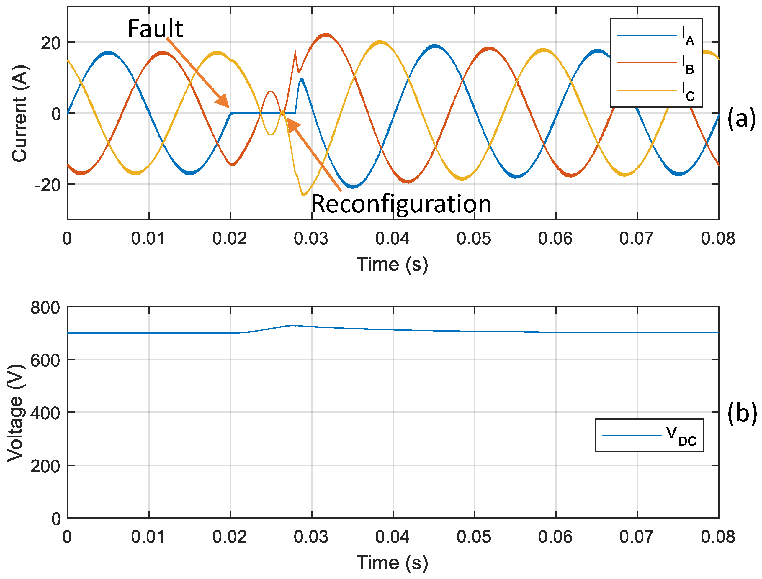
4. Results and Discussion

In a first simulation, an open-circuit fault is simulated on switch S AT at time t = 0.02 s . After the detection and localization of the faulty switch, the system is reconfigured by enabling TRIAC T A and redirecting phase A switching signals to the redundant switching leg, as it can be seen in the grid currents that are shown in Figure 4a. Normal operation is achieved after a few ms transient. Figure 4b allows verifying that the DC bus voltage is affected within reasonable limits and its control is kept during the fault detection and reconfiguration interval.
Figure 5 shows the result of a second simulation, where an open-circuit fault occurs on switch S pv 1 at time t = 0.02 s . The inductor current (Figure 5b) drops to zero immediately after the fault occurs. After 2.5 ms, the fault is detected by the DC-DC stage fault-diagnosis algorithm and the converter reconfiguration is performed by enabling TRIAC T pv 1 and redirecting the S pv 1 switching signal to redundant leg S RB switch. As in the previous case, normal operation is achieved after a few ms transient (Figure 5a).
According to the results, the proposed fault-tolerant converter structure is feasible, since, after a fault occurs, the converter reconfiguration can be performed without incurring in harmful current and voltage values that could damage the healthy devices.
Figure 6 shows the reliability as a function of time (11) of the proposed fault-tolerant PV multistring inverter. In this figure, the reliability of the conventional structure without fault-tolerant capability is also given. It can be seen from Figure 6 that the reliability of the system is significantly improved by introducing the fault-tolerant capability.
Table 4 provides the MTTF for the fault-tolerant PV multistring inverter (12) and the conventional structure. Through the introduction of a single redundant leg, the MTTF of the system is then improved by 96%. The fact that the MTTF of the system is improved by a factor of almost two makes the proposed fault-tolerant solution very attractive. Making an acceptable guess, the results that are presented in Table 4 can be translated to total lifetime by assuming 8 hours of operation per day, leading to about 10 years of lifetime for the conventional structure; meanwhile, it is more than 20 years for the proposed fault-tolerant converter.

5. Economic Impact Evaluation

This section provides a short evaluation of the potential impact of the proposed fault-tolerant solution from an economical point of view. First, an evaluation of the investment cost is given. The proposed fault-tolerant converter has more switching components, which implies higher costs than the conventional solution that consists of a two-stage two-level three-phase inverter. According to [31], the semiconductor-component and ancillary-circuit cost of the conventional solution amounts to about 12% of the total converter cost. Thus, because the proposed solution requires 20% more switches (12 IGBTs as compared to the 8 to 10 IGBTs present in the conventional configuration), it can be stated that the cost of such equipment is 2% to 3% higher.
Additionally, inverter failure leads to an average power loss in PV applications of more than 35% [3,5]. Thus, thanks to the proposed redundant system doubling the lifetime of the inverter, this power loss is expected to be reduced a 50%. Failures in inverters in PV applications usually lead to a reduction of the performance ratio of 5% to 6% [32]. With the proposed fault-tolerant inverter, this reduction is expected to be lower, around 3%.

6. Conclusions

This paper proposes a reliability assessment of a fault-tolerant PV multistring inverter. The proposed fault-tolerant converter consists of a conventional PV multistring converter with the addition of a single redundant leg and the reconfiguration hardware. The reliability estimation that was performed in this paper shows that, with the introduction of the fault-tolerant capability, the MTTF of the converter is improved by 96%, effectively doubling the power converter lifetime when compared with the conventional non-fault-tolerant structure. Moreover, it allows for reducing, by half, the power loss due to system-failure shutdowns in PV applications. Considering also that the increase in the converter cost is only between 2% to 3%, the proposed fault-tolerant PV multistring inverter is very attractive for applications where maintenance is difficult, such as PV plants in remote areas and applications where the reliability is critical, for example, when the PV source is the main or single source of energy in a micro-grid. Moreover, the simulation results prove that the fault-tolerant converter structure is feasible when proper fault-diagnosis algorithms are employed.

Author Contributions

P.P.-S., L.T., and J.L.D.-G. conceived the research idea. H.R. developed the converter model, performed the simulations, and prepared the first draft of the paper. H.R., D.C., A.F.-M. developed the reliability analysis. A.F.-M. performed writing–review and editing. P.P.-S., L.T., and J.L.D.-G. supervised the research. All authors have read and agreed to the published version of the manuscript.

Funding

This research has received funding from the European Union’s Horizon 2020 research and innovation programme under the project SUPERPV (grant agreement No 792245) and from AGAUR under the project CORV (with reference 2019 LLAV 00045).

Acknowledgments

The authors acknowledge the support provided by AC3E(ANID/Basal/FB0008).

Conflicts of Interest

The authors declare no conflict of interest.

Appendix A. Adjustment Factors

Adjustment factors for component failure rate calculation [27] are given in Table A1. Component temperatures are obtained through simulations, considering an ambient temperature of 40   ° C .
Table A1. Adjustment factors for component failure rate calculation [27].
VariableDescriptionExpression/ValueComment
λ C 1 Capacitor failure rate λ b · π T · π C · π V · π S R · π Q · π E = 0.0259Units in FIT (failures/ 10 6 h)
λ b Failure base rate0.00012Aluminium electrolytic capacitor
π T Temperature factor e x p 0.35 8.617 · 10 5 1 T + 273 1 298 T = 40   ° C , where T is the
capacitor operating temperature
π C Capacitance factor C 0.23 C = 1800   μ F , where C is the
capacitance in μ F
π V Voltage stress factor 1 + S C 0.6 5 -
π Q Quality factor10Commercial
π E Environment factor1Indoor operation
S C Voltage stress ratio V C V C , m a x V C = 330   V and V C , m a x = 550   V ,
where V C is the operating voltage and
V C , m a x is the capacitor rated voltage
λ C D C Capacitor failure rate λ b · π T · π C · π V · π S R · π Q · π E = 0.0533Units in FIT
λ b Failure base rate0.00051Metallized plastic film capacitor
π T Temperature factor e x p 0.15 8.617 · 10 5 1 T + 273 1 298 T = 40   ° C
π C Capacitance factor C 0.09 C = 1000   μ F
π V Voltage stress factor 1 + S C 0.6 5 -
π Q Quality factor10Commercial
π E Environment factor1Indoor operation
S C Voltage stress ratio V C V C , m a x V C = 800   V and V C , m a x = 1000   V
λ L 1 , λ L 2 Inductor failure rate λ b · π T · π Q · π E = 0.000111Units in FIT
λ b failure base rate0.00003Fixed inductor
π T Temperature factor e x p 0.11 8.617 · 10 5 1 T + 273 1 298 T = 40   ° C , where T is the
inductor operating temperature
π Q Quality factor3Lower than MIL-spec
π E Environment factor1Indoor operation
λ I G B T 1 IGBT failure rate λ b · π T 1 · π A · π Q · π E = 2.93Units in FIT
λ I G B T 2 IGBT failure rate λ b · π T 2 · π A · π Q · π E = 2.77Units in FIT
λ b Failure base rate0.006Half of the λ b of a MOSFET
π T i Temperature factor e x p 1925 1 T i + 273 1 298 T 1 = 141   ° C and T 2 = 136   ° C ,
where T i is the IGBT junction
temperature and i = { 1 , 2 }
π A Application factor10Power supply 350   W
π Q Quality factor8Plastic
π E Environment factor1Indoor operation
λ D 1 Diode failure rate λ b · π T 1 · π S · π C · π Q · π E = 1.14Units in FIT
λ D 2 Diode failure rate λ b · π T 2 · π S · π C · π Q · π E = 0.916Units in FIT
λ b Failure base rate0.025Fast recovery
π T i Temperature factor e x p 3091 1 T i + 273 1 298 T 1 = 131   ° C and T 2 = 120   ° C ,
where T i is the diode junction
temperature and i = { 1 , 2 }
π S Voltage stress factor V S 2.43 -
π C Construction factor1Metallurgically bonded
π Q Quality factor8Plastic
π E Environment factor1Indoor operation
V S Voltage stress ratio V D V D , m a x V D = 800   V and V D , m a x = 1200   V ,
where V D is the diode blocking voltage
and V D , m a x is the diode rated voltage
λ T 1 TRIAC failure rate λ b · π T 1 · π R · π S · π Q · π E = 0.0978Units in FIT
λ T 2 TRIAC failure rate λ b · π T 2 · π R · π S · π Q · π E = 0.0727Units in FIT
λ b Failure base rate0.0022All types
π T i Temperature factor e x p 3082 1 T i + 273 1 298 T 1 = 44   ° C and T 2 = 54   ° C ,
where T i is the TRIAC junction
temperature and i = { 1 , 2 }
π R Current rating factor4.8TRIAC rated at 50 A
π S Voltage stress factor V S 1.9 -
π Q Quality factor8Plastic
π E Environment factor1Indoor operation
V S Voltage stress ratio V T V T , m a x V T = 800   V and V T , m a x = 1200   V ,
where V T is the TRIAC blocking voltage
and V T , m a x is the TRIAC rated voltage

References

  1. Song, Y.; Wang, B. Survey on Reliability of Power Electronic Systems. IEEE Trans. Power Electron. 2013, 28, 591–604. [Google Scholar] [CrossRef]
  2. Wang, H.; Liserre, M.; Blaabjerg, F. Toward Reliable Power Electronics: Challenges, Design Tools, and Opportunities. IEEE Ind. Electron. Mag. 2013, 7, 17–26. [Google Scholar] [CrossRef] [Green Version]
  3. Golnas, A. PV System Reliability: An Operator’s Perspective. IEEE J. Photovolt. 2013, 3, 416–421. [Google Scholar] [CrossRef]
  4. Formica, T.J.; Khan, H.A.; Pecht, M.G. The Effect of Inverter Failures on the Return on Investment of Solar Photovoltaic Systems. IEEE Access 2017, 5, 21336–21343. [Google Scholar] [CrossRef]
  5. Lillo-Bravo, I.; González-Martínez, P.; Larrañeta, M.; Guasumba-Codena, J. Impact of Energy Losses Due to Failures on Photovoltaic Plant Energy Balance. Energies 2018, 11, 363. [Google Scholar] [CrossRef] [Green Version]
  6. Wu, R.; Blaabjerg, F.; Wang, H.; Liserre, M.; Iannuzzo, F. Catastrophic failure and fault-tolerant design of IGBT power electronic converters—An overview. In Proceedings of the 39th Annual Conference of the IEEE Industrial Electronics Society, Vienna, Austria, 10–13 November 2013; pp. 507–513. [Google Scholar]
  7. Choi, U.; Blaabjerg, F.; Lee, K. Study and Handling Methods of Power IGBT Module Failures in Power Electronic Converter Systems. IEEE Trans. Power Electron. 2015, 30, 2517–2533. [Google Scholar] [CrossRef]
  8. Kim, T.; Lee, W.; Hyun, D. Detection Method for Open-Circuit Fault in Neutral-Point-Clamped Inverter Systems. IEEE Trans. Ind. Electron. 2009, 56, 2754–2763. [Google Scholar]
  9. Yaghoubi, M.; Moghani, J.S.; Noroozi, N.; Zolghadri, M.R. IGBT Open-Circuit Fault Diagnosis in a Quasi-Z-Source Inverter. IEEE Trans. Ind. Electron. 2019, 66, 2847–2856. [Google Scholar] [CrossRef]
  10. Zhang, W.; Xu, D.; Enjeti, P.N.; Li, H.; Hawke, J.T.; Krishnamoorthy, H.S. Survey on Fault-Tolerant Techniques for Power Electronic Converters. IEEE Trans. Power Electron. 2014, 29, 6319–6331. [Google Scholar] [CrossRef]
  11. Karimi, S.; Poure, P.; Saadate, S. Fast power switch failure detection for fault tolerant voltage source inverters using FPGA. IET Power Electron. 2009, 2, 346–354. [Google Scholar] [CrossRef]
  12. Errabelli, R.R.; Mutschler, P. Fault-Tolerant Voltage Source Inverter for Permanent Magnet Drives. IEEE Trans. Power Electron. 2012, 27, 500–508. [Google Scholar] [CrossRef]
  13. Pradeep Kumar, V.V.S.; Fernandes, B.G. A Fault-Tolerant Single-Phase Grid-Connected Inverter Topology with Enhanced Reliability for Solar PV Applications. IEEE J. Emerg. Sel. Top. Power Electron. 2017, 5, 1254–1262. [Google Scholar] [CrossRef]
  14. Jamshidpour, E.; Poure, P.; Saadate, S. Photovoltaic Systems Reliability Improvement by Real-Time FPGA-Based Switch Failure Diagnosis and Fault-Tolerant DC–DC Converter. IEEE Trans. Ind. Electron. 2015, 62, 7247–7255. [Google Scholar] [CrossRef] [Green Version]
  15. Guilbert, D.; Gaillard, A.; N’Diaye, A.; Djerdir, A. Power switch failures tolerance and remedial strategies of a 4-leg floating interleaved DC/DC boost converter for photovoltaic/fuel cell applications. Renew. Energy 2016, 90, 14–27. [Google Scholar] [CrossRef]
  16. Poon, J.; Jain, P.; Konstantakopoulos, I.C.; Spanos, C.; Panda, S.K.; Sanders, S.R. Model-Based Fault Detection and Identification for Switching Power Converters. IEEE Trans. Power Electron. 2017, 32, 1419–1430. [Google Scholar] [CrossRef]
  17. Filba-Martinez, A.; Alepuz, S.; Busquets-Monge, S.; Luque, A.; Bordonau, J. An Intelligent Electronic Fuse (iFuse) to Enable Short-Circuit Fault-Tolerant Operation of Power Electronic Converters. TechRxiv 2020. [Google Scholar] [CrossRef]
  18. An, Q.; Sun, L.; Zhao, K.; Sun, L. Switching Function Model-Based Fast-Diagnostic Method of Open-Switch Faults in Inverters Without Sensors. IEEE Trans. Power Electron. 2011, 26, 119–126. [Google Scholar] [CrossRef]
  19. Kamel, T.; Biletskiy, Y.; Chang, L. Fault Diagnoses for Industrial Grid-Connected Converters in the Power Distribution Systems. IEEE Tran. Ind. Electron. 2015, 62, 6496–6507. [Google Scholar] [CrossRef]
  20. Im, W.; Kim, J.; Lee, D.; Lee, K. Diagnosis and Fault-Tolerant Control of Three-Phase AC–DC PWM Converter Systems. IEEE Trans. Ind. Appl. 2013, 49, 1539–1547. [Google Scholar] [CrossRef]
  21. Peuget, R.; Courtine, S.; Rognon, J. Fault detection and isolation on a PWM inverter by knowledge-based model. IEEE Trans. Ind. Appl. 1998, 34, 1318–1326. [Google Scholar] [CrossRef]
  22. Shahbazi, M.; Poure, P.; Saadate, S.; Zolghadri, M.R. FPGA-Based Reconfigurable Control for Fault-Tolerant Back-to-Back Converter Without Redundancy. IEEE Trans. Ind. Electron. 2013, 60, 3360–3371. [Google Scholar] [CrossRef] [Green Version]
  23. Huang, Z.; Wang, Z.; Zhang, H. Multiple Open-Circuit Fault Diagnosis Based on Multistate Data Processing and Subsection Fluctuation Analysis for Photovoltaic Inverter. IEEE Tran. Instrum. Meas. 2018, 67, 516–526. [Google Scholar] [CrossRef]
  24. Ribeiro, E.; Cardoso, A.J.M.; Boccaletti, C. Fault-Tolerant Strategy for a Photovoltaic DC-DC Converter. IEEE Trans. Power Electron. 2013, 28, 3008–3018. [Google Scholar] [CrossRef]
  25. Freire, N.M.A.; Estima, J.O.; Marques Cardoso, A.J. Open-Circuit Fault Diagnosis in PMSG Drives for Wind Turbine Applications. IEEE Trans. Ind. Electron. 2013, 60, 3957–3967. [Google Scholar] [CrossRef]
  26. Estima, J.O.; Freire, N.M.A.; Cardoso, A.J.M. Recent advances in fault diagnosis by Park’s vector approach. In Proceedings of the 2013 IEEE Workshop on Electrical Machines Design, Control and Diagnosis (WEMDCD), Paris, France, 11–12 March 2013; pp. 279–288. [Google Scholar]
  27. MIL-HDBK-217F. Reliability Prediction of Electronic Equipment. Available online: https://snebulos.mit.edu/projects/reference/MIL-STD/MIL-HDBK-217F-Notice2.pdf (accessed on 9 December 2020).
  28. Ristow, A.; Begovic, M.; Pregelj, A.; Rohatgi, A. Development of a Methodology for Improving Photovoltaic Inverter Reliability. IEEE Trans. Ind. Electron. 2008, 55, 2581–2592. [Google Scholar] [CrossRef]
  29. Song, Y.; Wang, B. A hybrid electric vehicle powertrain with fault-tolerant capability. In Proceedings of the 2012 Twenty-Seventh Annual IEEE Applied Power Electronics Conference and Exposition (APEC), Orlando, FL, USA, 5–9 February 2012; pp. 951–956. [Google Scholar]
  30. Sangwongwanich, A.; Yang, Y.; Sera, D.; Blaabjerg, F. Lifetime Evaluation of Grid-Connected PV Inverters Considering Panel Degradation Rates and Installation Sites. IEEE Trans. Power Electron. 2018, 33, 1225–1236. [Google Scholar] [CrossRef] [Green Version]
  31. Photong, C. A Current Source Inverter with Series AC Capacitors for Transformerless Grid-Tied Photovoltaic Applications. Ph.D. Thesis, University of Nottingham, Nottingham, UK, 2013. [Google Scholar]
  32. De Prada-Gil, M.; Domínguez-García, J.; Trilla, L.; Gomis-Bellmunt, O. Technical and economic comparison of various electrical collection grid configurations for large photovoltaic power plants. IET Renew. Power Gener. 2017, 11, 226–236. [Google Scholar] [CrossRef]
Figure 1. Proposed fault-tolerant photovoltaic (PV) multistring inverter.
Energies 13 06525 g001
Figure 2. Distribution of the components failure rate.
Energies 13 06525 g002
Figure 3. Markov-chain diagram of the whole fault-tolerant converter system. The subsystem defined by the capacitors and inductors is represented in dashed lines.
Energies 13 06525 g003
Figure 4. Simulation of an open-circuit fault on switch S AT . (a) grid currents. (b) DC-link voltage.
Energies 13 06525 g004
Figure 5. Simulation of an open-circuit fault on switch S pv 1 . (a) grid currents. (b) PV1 current.
Energies 13 06525 g005
Figure 6. Reliability functions of the proposed fault-tolerant converter and the conventional non-fault-tolerant converter.
Energies 13 06525 g006
Table 1. References and number of elements of the selected components.
ComponentTotal Number
of Elements
ReferenceComments
C pv 1 , C pv 2 , C pv 3 12ALS61A182MM550Two parallel strings per phase.
Each string formed by two capacitors in series
L pv 1 , L pv 2 , L pv 3 3195E50One inductor per phase
C DC 20MKP1848C71010JY5All capacitors in parallel
L f 3RTLX50One inductor per phase
IGBTs + diodes11 + 14SKM50GB12T4-
TRIACs5SK45UT-
Table 2. Parameters of the proposed system.
ParameterValue
Rated power 20   k W
V pvk 660   V
Grid voltage 400   V RMS
V DC 800   V
C pvk 1800   μ F
L pvk 2.5   m H
C DC 2000   μ F
L f 588   μ H
r f 352   m Ω
DC-DC stage switching frequency 20   k Hz
DC-AC stage switching frequency 10   k Hz
Grid frequency 50   Hz
Table 3. Variables defining the failure rate per component.
ComponentVariable
C pv 1 , C pv 2 , C pv 3 λ C 1
L pv 1 , L pv 2 , L pv 3 λ L 1
C DC λ C D C
L fA , L fB , L fC λ L 2
IGBTs (DC-DC stage) λ I G B T 1
IGBTs (DC-AC stage) λ I G B T 2
Diodes (DC-DC stage) λ D 1
Diodes (DC-AC stage)
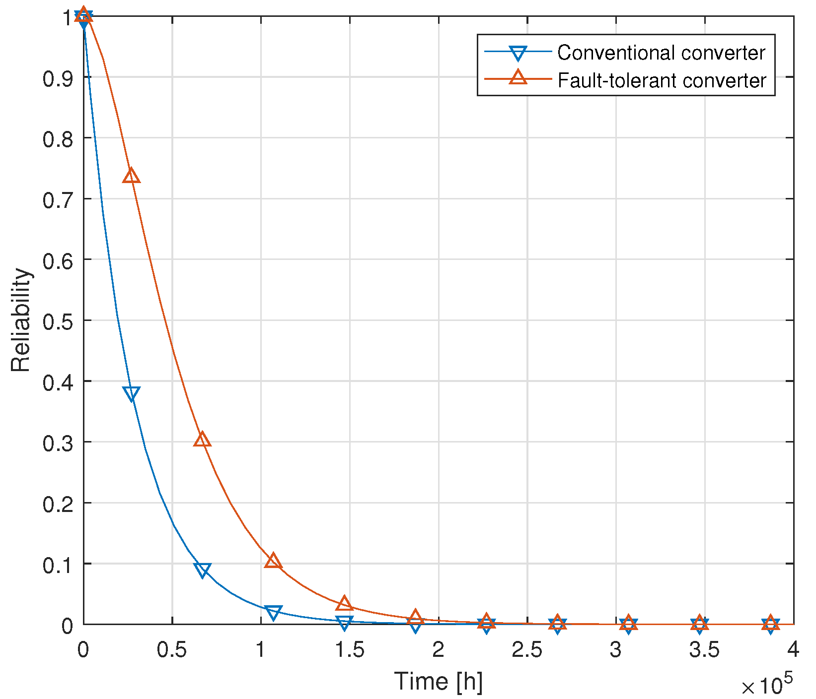
 λ D 2
T pv 1 , T pv 2 , T pv 3 λ T 1
T A , T B , T C λ T 2
Table 4. Mean time to failure (MTTF) of the considered topologies.
TopologyMTTF
Conventional converter3.20 years
Fault-tolerant converter6.26 years
Publisher’s Note: MDPI stays neutral with regard to jurisdictional claims in published maps and institutional affiliations.

