Abstract
Metallic interconnects represent the main component of a solid oxide fuel cell (SOFC) stack in terms of weight and volume. They are typically made of ferritic stainless steel (FSS) coated on the air side. At the stack operating conditions, the interconnect is exposed to a dual atmosphere: air at the cathode side; fuel (a hydrogen-rich mixture) at the anode side. The stacks considered in this study were field operated in reformed natural gas for 5000, 9000 and 20,000 h respectively. The analyzed interconnects are made from CROFER22APU and coated on the air side with Co-Mn base spinel. One interconnect has been studied for each stack by sampling and preparing cross section the inlet and outlet positions. The samples were characterized by SEM-EDXS in order to investigate the evolution of the interconnect at the air side. The interaction between the metal substrate and the coating is investigated highlighting the formation of chromia based thermal grown oxide (at the FSS/coating interface) and the solid-state diffusion of Cr and Fe from the metal into the coating. The microstructural features evolving as a function of time are also quantified.
1. Introduction
In the last few decades, studies have focused on the priority of producing technologically efficient power sources by also limiting environmental damages. From this perspective, solid oxide fuel cells (SOFCs) have reached a certain technology readiness level for a clean method of electric energy production using hydrogen (or hydrogen rich gases) as fuel. [1,2,3].
Each SOFC consists of a cathode, an anode and an electrolyte and is electrically joined to the adjacent ones through metallic interconnects (MICs) in order to achieve the voltage output needed for practical applications (a single SOFC produces around 1 V at open circuit potential) [4,5,6]. In addition, MICs act as a physical barrier to separate fuel (at the anode) from oxidant gases (at the cathode) and represent the main component of an SOFC stack in terms of weight and volume [4,5,6,7]. The physical and chemical properties of the MIC are modulated in order to obtain good and reliable performances of the entire SOFC at high temperatures [8]. These components are typically made of ferritic stainless steels (FSSs) that have a suitable oxidation resistance, a coefficient of thermal expansion (CTE) matching with the one of the other components of the fuel cells (11.5–14.0 × 10⁻⁶ K−1 from room temperature to 800 °C), good thermal and electrical conductivity, good manufacturability, suitable mechanical properties, easy fabricability, and affordable costs [6,7,9,10,11]. In particular, CROFER22APU, CROFER22H and AISI441 are grades commonly used as MICs for these applications [12,13,14,15,16,17]. Their high Cr content promotes the growth of: (i) a protective Cr2O3 scale; (ii) a Cr-Mn spinel as a top layer thanks to the presence of Mn in the alloy (with contents below 1 wt%) [18,19]. This outer layer is meant to control the oxide growth rate and to hinder the Cr evaporation [11,20,21,22,23,24].
At the stack operating conditions, the interconnect is exposed to a dual atmosphere with air at the cathode side and a hydrogen-rich mixture at the anode side [25,26,27]. At the cathode side, if the surface of the MIC is left unprotected, the thermally grown oxide (TGO) developed on the FSS reacts with oxygen and water vapor to form volatile Cr(VI)-species that migrate and deposit at triple phase boundaries (TPB), causing significant reduction in the performance of the SOFCs [28]. In order to limit the effects of this degradation phenomenon, namely ‘Cr-poisoning’, the metallic interconnect (MIC) is usually coated with a stable and protective layer which minimizes Cr evaporation [24]. Co-Mn and Cu-Mn spinel oxides are considered as promising candidates among a variety of coatings thanks to their high conductivities, good capabilities in retarding the oxidation of the MIC and suppressing the vaporization of chromium [24,29,30]. Usually the contact between the coated interconnect and the cathode is obtained by an electrically conductive perovskite, mainly LaSrCoFeO3 (LSCF), LaSrMnO3 (LSM) or LaSrCoMnO3 (LSCM) which further prevent cathode poisoning [31,32,33]. However, interactions between the coating and the TGO are inevitable during long term operation conditions and the performances of the SOFC can be influenced by the interdiffusion of the elements inside this composite layer. In this perspective careful characterizations of the physical and chemical properties of both the TGO and the coating are needed to understand this phenomenon.
On the fuel side the MIC is usually left uncoated. The contact between MIC and anode is typically done by a nickel base layer. SOFC anodes are usually made of Ni-based cermet for their high electronic conductivity, good catalytic activity for the electrochemical oxidation of hydrogen and stability under H2/H2O fuel conditions [34,35,36]. The physical laws governing this system are still under investigation and appear to be more complex compared to the ones observed at the cathode side since minimal modifications of variables as temperature or composition of the fuel (as subsequently partial pressures of the components of the mix) can strongly influence the behavior of the MIC.
In this work the attention is focused on the study of the MIC interactions at the air side (cathodic) with the other SOFC components in a system operating under real conditions and for sufficient periods of time to observe their evolution inside a stack. This is a topic which very few studies focused on [37,38] and is still under consideration due to the poor information on long term performances of the SOFC. Furthermore, this information is necessary in order to make reliable models and validate with actual cases studies that are presented in literature. In particular, the MIC of the stacks of ADASTRA EU PROJECT (Grant Agreement No 825027) are operated under real system conditions and studied post-mortem. The abovementioned project gives the unique opportunity to gain important information on the matter and to apply a suitable investigation protocol to MICs of the stacks belonging to the same manufacturer and aged in very similar conditions. In particular, the attention is focused on the evolution of the interface coating/TGO of stacks operating at 850 °C for 5000, 9000 and 20,000 h, respectively.
2. Materials and Methods
2.1. Materials and Operating Parameters
The SOFC stacks were manufactured and operated (according to the disclosable working conditions listed in Table 1) by Sunfire company (Sunfire GmbH, Dresden, Germany).

Table 1.
Operating parameters for the stacks, from 5000 to 20,000 h. The nominal operating temperature and the current density are the same for all stacks.
In the results section the stacks are indicated according to the operating time and site of analysis. The changes expected from inlet to outlet were the composition of the fuel stream due to the increase of pH2O, the current applied and the temperature gradient. No further details can be shared since all additional data are proprietary SUNFIRE information.
The stacks manufactured according to company standards used electrolyte supported cells based on 3YSZ as the electrode, with electrodes made of LSM (cathode) and Ni-GDC cermet (anode). Each cell was connected to the neighboring ones by MIC coated with a cobalt manganese spinel oxide (MCO) doped with Fe at the air side only. The MIC corresponds to an undulated plate of ferritic stainless steel CROFER22APU, commercial grade (Table 2), joined to the cell electrolyte by a proprietary glass-ceramic compliant sealant.
Table 2.
Crofer22APU Chemical composition (wt%) according to the ThyssenKrupp datasheet [39].
On the air side the MCO, protective coating was applied on the bare metal with an initial porosity and Fe content unknown due to the proprietary application method. The coating covers the whole surface following the ribs/channels profile with a constant thickness. On top of the ribs a contacting paste made of LSCM was applied in order to improve the electrical contact between the interconnect and the cathode of the cell.
2.2. Samples Preparation and Characterization
After operation, the stacks were carefully disassembled by the company and one MIC of each stack was prepared for further investigation. Samples were received complete and were documented before characterization to observe the surface features subjected to air stream. They were then mounted in epoxy resin before proceeding to the cut of the desired cross section. This step is needed to limit the manipulation of the surface and avoid any structural damage to the MIC. Two sites of interest, namely gas inlet (defined as IN) and gas outlet (OUT) were sampled in order to study changes related to the position in the cell. The choice of the site of sampling was instrumental to the characterization of the stack itself because they represent the extrema of the system (lowest temperature and pH2O at the IN and vice versa at the OUT). Figure 1a displays the sampling sites chosen for the investigation.
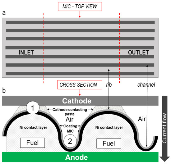
Figure 1.
Schematic representation of: (a) top view of a metallic interconnect (MIC), with marked IN and OUT sampling sites; (b) cross section of MIC in contact with anode and cathode with indications of the sites of analyses (1, 2). The sketch is representative of the proprietary design of the stacking sequence.
After the cut, each sample was further mounted in epoxy resin and polished following the ASTM E3-11 (2017) procedure. A pre-polishing with grinding paper (SiC) from 180 to 1000 grit was followed by polishing with polycrystalline diamond suspensions from 6 µm to 0.25 µm. The surface was checked at each step by optical microscope and then coated with gold by magnetron sputtering before performing the scanning electron microscopy (SEM) investigation.
SEM characterization (Zeiss Evo40; Carl Zeiss, Oberkochen, Germany) was carried out on the cross section. Chemical analyses were performed with energy-dispersion X-ray spectroscopy (EDS; Cambridge INCA 300 with PentaFET EDXS detector; Oxford Instruments, Oxfordshire, U.K. sensitive to light elements, Z > 5) connected to a SEM on at least 5 sites of interest to have a good data dispersion and reproducibility. Values below 0.3 at.% were considered as semi-quantitative and thus not discussed in detail. Image analysis was performed using the Software Fiji-ImageJ, version 1.49b [40] to estimate the thickness and the porosity of the layers observed. Mathematical calculations for the rate constants (Kp) of the TGO and for the minimum concentration of Cr ( in the alloy were carried out using OriginLab.
3. Results
3.1. Surface Observations of the MIC
Figure 2 displays the macroscopic evolution of the MIC operated up to 20,000 h at the air side. For clarification, two areas will be described in the sections, called ribs and channels according to the design of the MIC. These are highlighted in Figure 2. From a macroscopic examination, the entire surface is visibly coated with the MCO spinel oxide and, on some parts of the ribs only, with the LSCM contacting paste. This could be attributed to the mechanical manipulation of the samples prior to the analyses.
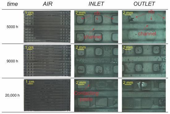
Figure 2.
Macroscopic evolution of the MIC operated up to 20,000 h at the air side. IN and OUT most representative sites were also displayed.
The ribs have a change in shape in the initial final parts where there is a sequence of three squares per each side. The central part is homogeneous and corresponds to a better distribution of the air stream. The IN and OUT are taken in this part.
The macroscopic appearance of the ribs and the channels evolves according to the working time. The ribs, which are in contact with the air electrode (cathode), appear unchanged in all samples at 5000 h and 9000 h. However, light green areas were noticed at the OUT at 20,000 h. Further investigations of the surface with the SEM did not show changes in the composition of the layer of LSCM. From the EDS analyses on the 20,000 h OUT, no Cr and/or Fe was detected (Figure S1, Supplementary Materials). This means that, if present, those elements were below the limit of detection (<LOD) of the instrument. The presence of a further layer between the air and the coating apparently resulted in the absence of macroscopic changes, also suggesting that this system (MCO/LSCM) is protective against Fe and Cr diffusion towards the cathode.
The channels, on the other hand, showed small modifications in terms of color for both the IN and the OUT. At 5000 h rare darker spots were formed in the channels at the IN and from 9000 h dark green areas were visible (Figure 2). The observed color depended on various parameters, such as the grain size of the most superficial layer and the amount of residues belonging to the contacting paste. Beside the extreme care used by the person in charge while removing the interconnect from the stack, some damages might have occurred. From the macroscopic analyses a specific trend of distribution with time was not attested. Small differences in color were visible from the IN to the OUT at 20,000 h, where the channels show a predominance of green. From the SEM analyses, those specific areas did not differ in composition from the others. Some chemical modifications of the MCO were noticed instead. For both the IN and the OUT the EDS of the 20,000 h sample showed the presence of non-negligible concentrations of Fe and Cr at 2.9 ± 0.3 and 1.1 ± 0.1 at.%, respectively (see Figure S2, Supplementary Materials).
3.2. Cross Sections
3.2.1. Choice of the Sites of Analysis
Figure 1b shows a schematic representation of the MIC with the related layers and sites of interest for the investigation. Accordingly, different positions were chosen:
- Air/rib (position 1): area subjected to the electric current flow where the MCO coated MIC is interfaced with the LSCM cathode contact layer;
- Air/channel (position 2): area at the bottom between two ribs at air side, subjected only to the air flow, coated with MCO but not in contact with other materials.
3.2.2. Morphological Results
The position 1 (Figure 1b, position 1) is characterized by the presence of a TGO at the interface between the metal substrate and the MCO protective coating over the whole width [7]. The protective coating is covered with a layer of LSCM (LaSrCoMn oxide), visible on top of each rib of air side (see Figure 2, IN—20,000 h), acting as a contacting paste to enhance the electrons exchange between the cathode and the MIC [41]. This investigation allows the estimation of the coatings effectiveness to mitigate the oxide growth on the metal surface, the consequent chromium solid state diffusion towards the cathode (having hindered the Cr evaporation) and the time dependence under operating conditions of the structural and chemical features of the layers (i.e., coating).
Figure 3 displays the SEM micrographs of both the MIC IN and OUT at 5000, 9000 and 20,000 h and chosen positions (1, 2). The following sections will discuss the evolution of the morphology and composition of the TGO, the coating and the TGO/coating interface according to the sites IN, OUT and positions (Figure 1), focusing also on their differences.
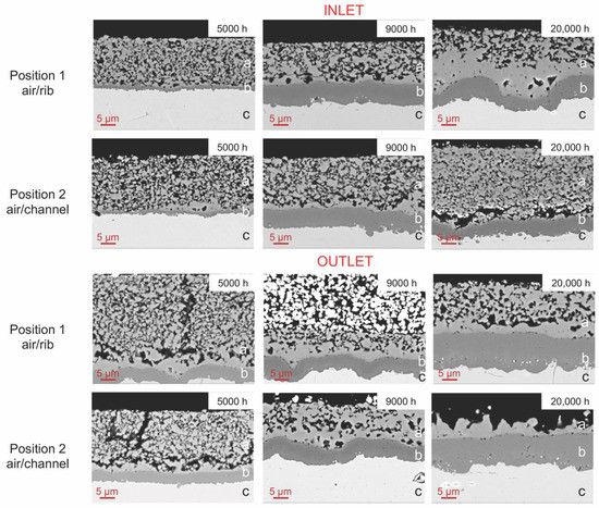
Figure 3.
SEM-BSE micrographs of the position 1 (air/rib interface) and position 2 (air/channel interface) from 5000 to 20,000 h. The phases as labelled as follows: (a) MCO; (b) thermally grown oxide (TGO); (c) ferritic stainless steel (FSS). The white porous phase above the MCO at OUT 9000 h is the LSCM contacting paste.
The TGO layer formed at the interface between the metal substrate and the coating displays a variation of thickness related to the local conditions of temperature [42]. The time dependence of the growth is visibly different from IN to OUT (Table 3) for both positions considered. Furthermore, for position 2, the oxidized layers are not subjected to the current flow and the coating is directly exposed to air for absence of a direct contact with the cathode.
Table 3.
Thickness variation of the TGO according to the exposition time, site of interest and sampling site. Average values with standard deviations in thickness on at least 5 measurements.
For both positions, a compact, continuous and adherent oxide layer is formed at the whole metal/coating interface (Figure 3). Its thickness changes according to the sampling site, with a 3–4 times higher value at the OUT compared to the IN at 5000 h. An increase in the scale thickness is detected at 9000 h for both IN and OUT (Table 3 and Figure 3) with comparable values for the considered positions. Additionally, the kinetics suggest a faster growth at the IN. Although the values are slightly lower in the air/channel than in the rib, it seems plausible to assume that the TGO growth rate is not affected by the polarization (current flow), the direct interaction with the air stream or the additional layer of LSCM. This thickness gradient must be verified and has to be related to a still not well understood variable (possibly a temperature gradient), locally changing from IN to OUT. However, this hypothesis does not completely fit, since position 2 shows different TGO thicknesses. It is only possible to assume that the decrease in scale growth rate over time could be possibly related to the densification of the protective layer, hindering the oxygen diffusion towards the metal substrate [30,31,32] and a related interaction with the LSCM contact layer. At 20,000 h, the TGO formed in position 1 at the interface between the coating and the metal substrate remains in the range of 7 to 8 μm at the IN while in the OUT the thickness increase is higher, reaching nearly 12 μm. Position 2 IN 20,000 h shows a rather low TGO thickness. By the observation of the corresponding representative picture in Figure 3 (IN pos. 2 20,000 h) the partial densification of the coating changed the mechanical properties of the coating and originated a fracture parallel to the MCO-MIC interface, exposing the densified MCO directly to the air stream. The crack created a gap that has strongly limited the oxygen diffusion toward the interface with the TGO of the metal substrate, predominantly affecting the MCO. For position 2 the OUT confirms the higher growth kinetic with a value close to the one observed in the rib of the same sample.
According to the position, the adhesion of the coating to the substrate modifies in time. While for position 1, the coating appears perfectly adherent to the substrate up to 20,000 h and the air/channel exhibits a partial detachment from 5000 h. Table 4 exhibits the quantification of the porosities, estimated on at least 5 different SEM sites of interest at the same magnification.
Table 4.
Porosity variation of the MCO coating according to the exposition time and sampling site. Average values with standard deviations in thickness on at least 5 measurements. n.m. = not measured. * = detached.
Generally, in terms of morphology the IN and the OUT exhibit comparable percentages of porosities, with the exceptions of position 1—5000 h and position 2—9000 h. Two structures are always visible at the OUT for both positions, with a dense layer of up to 2 μm appearing at the interface coating/TGO, probably connected to a densification process [43,44]. It is worth noticing that in the cross section of the OUT after 20,000 h of operating time (pos. 2) the MCO coating is stiff and thinner that in all other positions. This seems to be the combined effect of the abovementioned densification process and the mass loss due to the detachment of the most external layer. Such a hypothesis is supported by the presence of a well visible fracture in the IN sample (same position and aging time) and by the densification observed at the position 1 of the same sample. Furthermore, for position 2, cracks are observed between the densified layer and the porous one. The variations in the porosity observed between rib and channel at the same position and time might be linked to the local increase of temperature due to the current flow which is localized on the rib. However, the presence of the contacting layer may also play a role and further ex-situ experiments are planned to better understand such discrepancy. A densification process is nevertheless noticed as a result of the operating time. Larger crystals and a lower number of pores characterize the MCO feature (Figure 3). At the interface with the TGO the thickness of the dense MCO layer increases with time and temperature (if IN and OUT are compared). The gathered information lead to consider these observations as a result of a slow but visible sintering effect of the MCO. The lowered growth rate of the TGO seems to be related to the competing effect of both temperature (increasing the TGO grow rate [43]) and densification of the MCO (enhancing the efficiency). However, the number of defects of the coating at position 2 suggests the occurrence of cracking or delamination due to mechanical stresses developed during thermal cycling. It is only assumed that these stresses could be possibly connected to changes of the coefficient of thermal expansion (CTE) as a result of chemical transformations of the coating itself [45], not matching with those of the TGO and the metallic substrate, respectively.
3.2.3. Compositional Analysis
The evolution of the TGO is displayed in Figure 4 where a delay between position 1 and 2 is distinguished from the 5000 h. Only (Mn,Cr)3O4 is observed in the rib, while a composite layer made of inner (Mn,Cr)3O4 and outer Cr2O3 is detected at the channels. From the chemical point of view no difference is noted between the IN and the OUT of each position, therefore only positions will be discussed hereafter.
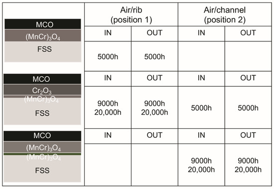
Figure 4.
Schematic representation of the TGO compositions found for each operating time; the differences in color of the (Mn,Cr)3O4 are related to the different levels of Mn inside the oxide: grey = Mn content up to 9 at.% and dark green = Mn content from 10 at.%.
Manganese is present at both interfaces TGO/FSS and TGO/MCO (Figure 5 and Figure S3 displays the SEM images and the sites of the analyses). Its diffusion from the metal substrate is a common phenomenon and usually leads to the formation of a Cr-Mn spinel oxide on top of the chromia base layer [46]. However, the presence of a Cr2O3 layer on top of the (Mn,Cr)3O4 in position 2 and not vice versa is still a not well understood phenomenon, as already pointed out in literature [43,46]. It can be only supposed that the mechanism of TGO formation under real life conditions is affected by the presence of multiple layers (i.e., coating, contacting layers) modifying the way oxygen reaches the metal surface. It is indeed suggested that mainly solid-state diffusion is the source of oxygen ions and, at the same time, the polarization occurring while in operation may change the behavior of ions diffusing into the TGO.
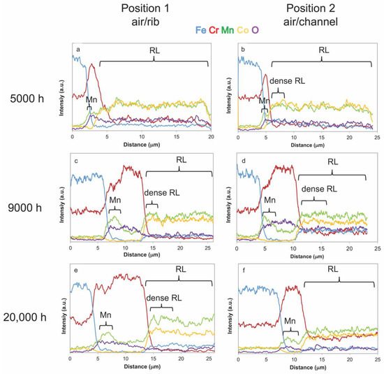
Figure 5.
Linescans profiles of different sites of interest based on the Kα energies of Cr, Mn, Fe, Co, O of the different positions: (a) IN sample at 5000 h position 1; (b) IN sample at 5000 h position 2; (c) IN sample at 9000 h position 1; (d) OUT sample at 9000 h position 2; (e) OUT sample at 20,000 h; (f) IN sample at 20,000 h RL = reaction layer. Figure S3 displays the SEM images and the sites of the analyses. The distance refers to the initial spot of analysis in the metal substrate (on the left of the black line) as shown by the presence of Fe as major element.
If the temperature is considered responsible for the differences in the TGO kinetics between IN and OUT, the same parameter does not seem to affect the Mn content into the chromia. The oxygen amount in the gas flow is considered quite similar regardless of the position between IN and OUT due to the fact that in case of oxygen depletion in the stream sever degradation of the cathode might occur [47].
The oxygen supply seems to come from the spinel acting as an oxygen carrier that diffuses from the external surface through the oxide [48,49]. At both the IN and the OUT at 9000 h, position 1, a double layer comparable to the 5000 h channel is distinguished from the EDS analyses. At the TGO/FSS interface Mn content is higher than that at the interface TGO/coating (Figure 5c), suggesting the presence of (Mn,Cr)3O4 below Cr2O3. This specific layer is 1/3 of the whole TGO thickness. Pure chromia (Cr2O3) constitutes the upper layer (ratio in at.% of 0.67). On the other hand, position 2 exhibits a different scale composition. An increase in the content of Mn inside the TGO indicate a composite layer of (Mn,Cr)3O4 where Mn is enriched at the interface with the FSS (Figure 5d). The spot analyses indicate 11 at.% of Mn in the inner layer, with values almost twice as high compared to the position 1 interface at the same time. The outer layer is made of (Mn,Cr)3O4 with average values of Mn around 3.5 ± 1 at.%. This confirms that pure Cr2O3 evolves into a (Mn,Cr)3O4. The same composition of the TGO observed in the previous samples is confirmed at 20,000 h for position 1 and 2. However, the length of the inner layer increases for both the positions and visible on 50% of the total TGO thickness (Figure 5e,f, linescans). This suggests that for position 2 the diffusion of Mn is accelerated, while the scale growth remains similar to the one found on the rib. As a matter of fact, the MCO might act as a source of Mn ions into the TGO [50], which is only visible in the 20,000 h operated sample at the outlet channel position.
The compositional evolution of the MCO coating was monitored according to the Fe, Cr, Mn and Co concentrations (in particular, Co:Mn ratio [45]). It results that Cr and Fe could have diffused from the TGO only while for Mn and Co an interdiffusion mechanism (also involving the LSCM) is more plausible. Figure 6a,b displays the sum of Fe and Cr in the MCO vs. time for both positions (1 and 2). The IN and OUT operating conditions affect the amount of Fe and Cr inside the coating and their evolution does not appear as a trend but rather stochastic. At 5000 h the highest Cr values are detected for the IN at the rib (see also Figure 5a), while small amounts of Cr are detected for 1 and 2 at the OUT.
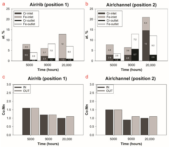
Figure 6.
Histograms of Cr and Fe content (at.%) and Co:Mn inside the coating according to the operating time and site of interest (IN, OUT): (a) stacked Fe and Cr position 1; (b) stacked Fe and Cr position 2; (c) Co:Mn position 1; (d) Co:Mn position 2.
The highest content of Fe is found in the channel cross-section at the IN position regardless of the operating time. A chemical enrichment of Fe at the interface TGO/MCO confirms that this element plays a role in the densification process, as displayed by the presence of a compact layer in that same region (Figure 5b and Figure S3), defined as reaction layer (RL) in literature [43,49,50,51]. This outcome is of difficult interpretation: it could suggest either an interaction of the TGO with the coating and outward diffusion of the elements or evolution of the coating itself. It is indeed important to highlight that the MCO is doped with Fe but its content inside the coating is proprietary information. According to the spot analyses (Figure 6) and the linescan (Figure 5c), at 9000 h a diffusion of Cr and Fe from the TGO is observed, with fluctuating values for both the IN and the OUT and the considered position. It is worth noting a general decrease of Cr and an increase of Fe. The effect of Fe, according to literature [37] seems to be mainly in diffusing in the densified coating this may eventually improving its electrons conductivity by forming a Fe doped MCO. However, for position 2 OUT also a sudden increase of Cr is noticed (Figure 5d). This mechanism is consistent with a further evolution of the RL detected up to 1000 h according to [51], where the stabilization of one phase of the spinel coating at the expense of another induces interdiffusion at the TGO/coating interface. Moreover, in literature, the presence of a RL made of (Co,Mn,Cr)3O4 and/or (Mn,Co,Cr,Fe)3O4 is proven by a densified layer [43,49,50,51]. At 20,000 h an increase of Fe inside the coating is detected at the IN with the highest value for position 1 (12 at.%). However, the different Cr content from position 1 to position 2 (Figure 5e,f) does not confirm the hypothesis that high Fe concentrations inside the MCO limit the Cr diffusion from the TGO [45]. This result is clearly described by the profile of Figure 5f, where the Cr Kα intensities are almost comparable to those of Mn and Co. This implies (as confirmed from the spot analyses) an atomic ratio for Co:Mn:Cr around 2:2:1 that would indicate the presence of a mixture of (MnCoCr)3O4 and Mn1.25Co1.25Cr0.5O4 [45]. For the OUT small changes in both Cr and Fe suggest a further interdiffusion process that involves only the sum of the two elements. To have a better idea of the changes in the MCO, variations in the Co:Mn at.% ratio with time are also considered (Figure 6c,d). At 5000 h the ratio is stable at 1.6, suggesting that nor the position or the IN/OUT influence their relative abundance inside the coating. The results obtained at 9000 h indicate lower Co:Mn ratios, reaching the lowest value for the OUT at the channel (0.9), proving a shift in the relative atomic values of the elements, possibly from a Co-rich to a Mn-rich as (Mn,Co,Cr,Fe)3O4 type. At 20,000 h, the evolution of the coating also involves the Mn and the Co ratio, as displayed by the linescan in Figure 5e,f. An increase in the relative content of Mn compared to Co is visible for the rib and the channel and is similar at IN and OUT positions. However, as aforementioned, also the Cr increases at position 2, this suggests faster kinetics of diffusion of the element inside the coating due to local conditions to be further investigated.
4. Discussion
The evolution of the system MCO/TGO follows the typical solid-state diffusion kinetics, with the formation of an RL suggesting the occurrence of interdiffusion phenomena. A delay in the chemical evolution of the oxide is correlated to the position in the stack (Figure 4). A preliminary interpretation for the obtained results could be the absence of a contacting paste for position 2, which is directly exposed to the air stream. The authors assume that the MCO fractures allow for the oxygen diffusion into the RL of the MCO. As confirmed by [45,49,52], the solid-state diffusion coefficient of Mn in the MCO is higher compared to those of the other elements according to the higher oxygen partial pressure. Therefore, its enrichment inside the TGO is mainly related to the relatively high oxygen availability of the MCO. Additionally, the lack of Co in the TGO supports the hypothesis that Fe inside the MCO inhibits Co diffusion via grain boundaries [49]. However, if the different oxygen availability is the rate determining step for both the MCO evolution and the TGO growth, the thicknesses of the TGO and the content of the elements on the MCO should have changed from the rib to the channel. This did not occur in the TGO, since at the IN a maximum of around 8 μm is reached while at the OUT the measured thickness is around 12 μm both at the rib and the channel. The TGO rate constants (Kp) displayed in Figure 7a according to Wagner’s law [53] confirm comparable growth kinetics for the rib and the channel and discrepancies according to the local operating conditions.
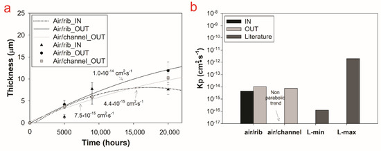
Figure 7.
(a) example of parabolic growth rate plot that best fits the values of thickness with time; (b) values of the Kp for the air side according sampling position (1, 2) and site of interest (IN, OUT) compared to minimum (min) and maximum (max) values found in literature (L).
The local operating temperature confirms the predominant role on the polarization and the oxygen availability as the parameter affecting the TGO formation and growth rate. The kinetics of the TGO must be connected to a more complex mechanism that primarily involves the oxygen ions diffusion across the MCO and the evolution of the RL. The evolution of the MCO is indeed influenced by the position (channel or rib) and the RL thickness increases in strong correlation to a diffusion regime established by the conditions and the operating time. Even if an almost comparable trend of diffusion of Fe and Cr is evidenced for the first 5000 h for both positions, modifications in time are detected (Figure 5). As shown, from 9000 h to 20,000 h their concentrations clearly change according to the sampling position (1 and 2) and partially the site of interest (IN, OUT). Therefore, the MCO evolution could be connected to both local operating conditions and positions. This means that faster kinetics due to a relatively higher oxygen availability and a higher temperature could promote a faster interdiffusion mechanism [43]. This is coherent with the constant increase of density of the coating at the interface with the metal substrate hindering the FSS/air possible interaction.
Considering the TGO, the data of Kp fall in the range of values from literature [43,45,54]. Keeping all approximations related to this model in mind one can extrapolate the TGO thickness at 50,000 h, a typical operating time for SOFC, obtaining an average of ca. 12–14 μm for the IN and of 17–20 μm for the OUT. Such results are perfectly aligned with the data obtained by Chen et al. [54], for the IN, and are satisfying in terms of overall performances of the stack. On the other hand, the OUT TGO data are more consistent with those of Zhu et al. [55], which are considered too thick to ensure good long-time performances. If we take into account the diffusion of the elements in the MCO, the presence of Cr and Mn inside the coating is connected to a generally well-known phenomenon [7,43,45,56,57]. However, the diffusion of Fe is a less expected one, and was only detected by Bianco et al. characterizing a real-life stack under operating conditions up to 18,000 h [37]. According to their results, the diffusion of Fe inside the coating could be related to a chemical or mechanical breakdown of the TGO (iron breakaway). In both circumstances, the evolution of the composition of the scale/coating is responsible for the diffusion of Fe inside the MCO. In any case, the diffusion of Fe inside the coating is not necessarily an issue since Fe-doped MCO are commonly used with a gain in the performances of the coating, being a more stable chemical barrier and a more efficient conductor [45,58,59]. Unfortunately, no hypothesis on the mechanical stability of the TGO can be drawn from this study as no specific analyses were carried out in such a sense. On the other hand, the chemical stability of the TGO is connected to the minimum concentration of in the alloy, necessary to form a passive layer at the interface with the environment, according to Equation (1) from Wagner et al. [53]:
where and are the molar fractions of the alloy and oxide. For clarity, the alloy interdiffusion coefficients were taken from the works of [60] and [61]. The results indicated a minimum concentration of Cr that ranges between 9.1 wt% and 16.8 wt%, with higher Cr concentration needed for the OUT. The values are partially coherent with what observed by Bianco et al. [37] for the cathode side and larger values of could be related to the different Kp obtained. Thus, CROFER22APU is able to form a passive layer of Cr2O3 and avoid Fe breakaway. Furthermore, the changes in composition from position 1 to 2, require further investigations and should be thoroughly understood. In addition, considering the possible diffusion mechanisms and the presence of other alloying elements, Wagner’s theory does not fully explain real life conditions. The metal substrate is covered by a spinel oxide (i.e., the MCO) used to decrease the oxidation rate of the metal and to hinder the formation of Cr rich volatile compounds due to a further oxidation of the TGO. The formation of such TGO is due to the interaction of the metal substrate with the coating that is the source of oxygen. A recent study proposed by Talic et al. [50] discusses the possible introduction of diffusion couples through a grain boundary mechanism that could be applied to the MCO/TGO interaction. Further investigation and specifically designed experiments are needed to better clarify such a mechanism in SOFC operating conditions.
5. Conclusions
The SOFC stack is a secondary power source of the highest importance to reach the target of green and reliable energy production. Its behavior all along the operating life (planned between 50,000 and 80,000 h) depends on the stability of its components: the cells (i.e., cathode, electrolyte and anode) and the stacking elements (i.e., interconnects, scaffoldings, sealants). Metallic interconnects are among the critical components due to their reactivity at operating conditions (e.g., high temperature, oxidizing atmosphere, polarization). This paper was focused on the investigation of MICs coming from field operated SOFC stacks for various amounts of time up to 20,000 h, and gathers the results from the surface and cross section characterization of complete interconnects. This was a real opportunity to feed the predictive models aimed at describing the stack behavior in time and to better design accelerated tests reaching comparable degradation features in a shorter experimental time.
This paper only investigated the air side of the interconnect where the metal substrate (Crofer22APU) is homogeneously coated with a protective layer of a MCO spinel and, on top of the ribs only, with the LSCM contacting paste used to enhance the interface between the cathode and the MIC. At the metal substrate/coating interface a Cr rich thermally grown oxide is formed due to the oxygen diffusion across the MCO. Such TGO is chromia based and layered in a Mn doped chromia at the metal interface and a chromia layer showing nearly no Mn at the interface with the coating. This layer grows in thickness with time and with the temperature. Two regions defined by fuel gas as well as air flow as IN and OUT. At the air side these two parts only differ by the local temperature—slightly lower than 850 °C at the IN and higher than 850 °C at the OUT (and most likely by Cr content).
The oxide growth rate is also related to the densification of the spinel coating, which slowly sinters. The temperature is enough to see an efficient sintering phenomenon and the long-lasting dwell time at ca. 850 K allows for an appreciation of the evolution of the microstructural features of the coating and of the contacting paste. No chromium deposition inside the contacting paste porosity was remarked, testifying the efficiency against Cr poisoning of the MCO. However, Cr and Fe were found in the spinel with a concentration growing with time (especially for Fe amount). This phenomenon is related to the solid-state diffusion and leads to what seems to be an improvement of the densification and electrical conductivity of the whole system MIC/MCO.
The temperature management within a stack is strictly related to the stack design, and it is quite complex to use data coming from one stack design to predict the behavior of another stack with a different design. However, the goal is to show that even little differences in temperature (ca. 50 °C in our specific case) affect the oxide growth rate. These are data to be used in the predictive models related to MIC/coating evolution under operating conditions. The main purpose of the project Ad Astra is to offer predictive instruments and specific experiments for the investigation of degradation phenomena in long lasting operations under working conditions. The evolution of the protective coating and the stability observed in the presence of the double layer MCO/LSCM will be considered for the future design of specific accelerated aging tests.
Supplementary Materials
The following are available online at https://www.mdpi.com/1996-1073/13/24/6487/s1, Figure S1: SEM micrograph an EDS analyses of the rib of the 20,000 h OUT. The presence of the LSCM contacting paste is highlighted by the results. Figure S2: SEM micrograph an EDS analyses of the valley of the 20,000 h OUT. The presence of a modified MCO coating is highlighted by the results. Figure S3: SEM-BSE micrographs at 5000x with linescan analyses also displayed in Figure 4.
Author Contributions
G.G., conceptualization, methodology, formal analysis, investigation, visualization, writing—original draft, review and editing; P.P., conceptualization, formal analysis, visualization, review and editing; V.B., formal analysis, visualization, investigation, writing—original draft, review and editing; C.G., material acquisition, review and editing of the final draft; R.S., review and editing, funding acquisition, supervision. All authors have read and agreed to the published version of the manuscript.
Funding
This work is part of the ADASTRA EU PROJECT which has received funding from the Fuel Cells and Hydrogen 2 Joint Undertaking under Grant Agreement No 825027. This Joint Undertaking receives support from the European Union’s Horizon 2020 research and innovation program and Hydrogen Europe.
Conflicts of Interest
The authors declare no conflict of interest.
References
- Choudhury, A.; Chandra, H.; Arora, A. Application of solid oxide fuel cell technology for power generation—A review. Renew. Sustain. Energy Rev. 2013, 20, 430–442. [Google Scholar] [CrossRef]
- Damo, U.M.; Ferrari, M.L.; Turan, A.; Massardo, A.F. Solid oxide fuel cell hybrid system: A detailed review of an environmentally clean and efficient source of energy. Energy 2019, 168, 235–246. [Google Scholar] [CrossRef]
- Fernandes, M.D.; Bistritzki, V.; Domingues, R.Z.; Matencio, T.; Rapini, M.; Sinisterra, R.D. Solid oxide fuel cell technology paths: National innovation system contributions from Japan and the United States. Renew. Sustain. Energy Rev. 2020, 127, 109879. [Google Scholar] [CrossRef]
- Öztürk, B.; Topcu, A.; Öztürk, S.; Cora, Ö.N. Oxidation, electrical and mechanical properties of Crofer®22 solid oxide fuel cell metallic interconnects manufactured through powder metallurgy. Int. J. Hydrogen Energy 2018, 43, 10822. [Google Scholar] [CrossRef]
- Qi, Q.; Wang, L.; Liu, Y.; Huang, Z. Oxidation resistance optimization of TiC/astelloy composites by adding Ta element applied for intermediate temperature solid oxide fuel cell interconnects. J. Power Sources 2018, 401, 1–5. [Google Scholar] [CrossRef]
- Mah, J.C.W.; Muchtara, A.; Somalu, M.R.; Ghazali, M.J. Metallic interconnects for solid oxide fuel cell: A review on protective coating and deposition techniques. Int. J. Hydrogen Energy 2019, 42, 9219–9229. [Google Scholar] [CrossRef]
- Wu, J.; Liu, X. Recent Development of SOFC Metallic Interconnect. J. Mater. Sci. Technol. 2010, 26, 293–305. [Google Scholar] [CrossRef]
- Sreedhar, I.; Agarwal, B.; Goyal, P.; Agarwal, A. An overview of degradation in solid oxide fuel cells-potential clean power sources. J. Solid State Electrochem. 2020, 24, 1239–1270. [Google Scholar] [CrossRef]
- Swaminathan, S.; Ko, Y.S.; Lee, Y.-S.; Kim, D.-I. Oxidation behavior and area specific resistance of La, Cu and B alloyed Fe-22Cr ferritic steels for solid oxide fuel cell interconnects. J. Power Sources 2017, 369, 13–26. [Google Scholar] [CrossRef]
- Lee, K.; Yoon, B.; Kang, J.; Lee, S.; Bae, J. Evaluation of Ag-doped (MnCo)(3)O-4 spinel as a solid oxide fuel cell metallic interconnect coating material. Int. J. Hydrogen Energy 2017, 42, 29511–29517. [Google Scholar] [CrossRef]
- Ryter, J.; Amendola, R.; McCleary, M.; Shong, W.-J.; Liu, C.-K.; Spotorno, R.; Piccardo, P. Effect of electrical current on the oxidation behavior of electroless nickel-plated ferritic stainless steel in solid oxide fuel cell operating conditions. Int. J. Hydrogen Energy 2018, 43, 426–434. [Google Scholar] [CrossRef]
- Park, M.; Shin, J.-S.; Lee, S.; Kim, H.-J.; An, H.; Ji, H.-I.; Kim, H.; Son, J.-W.; Lee, J.-H.; Kim, B.-K.; et al. Thermal degradation mechanism of ferritic alloy (Crofer 22 APU). Corros. Sci. 2018, 134, 17–22. [Google Scholar] [CrossRef]
- Sachitanand, R.; Sattari, M.; Svensson, J.-E.; Froitzheim, J. Evaluation of the oxidation and Cr evaporation properties of selected FeCr alloys used as SOFC interconnects. Int. J. Hydrogen Energy 2013, 38, 15328–15334. [Google Scholar] [CrossRef]
- Talic, B.; Molin, S.; Hendriksen, P.V.; Lein, H.L. Effect of pre-oxidation on the oxidation resistance of Crofer 22 APU. Corros. Sci. 2018, 138, 189–199. [Google Scholar] [CrossRef]
- Hosseini, N.; Karimzadeh, F.; Abbasi, M.H.; Choi, G.M. Correlation between microstructure and electrical properties of Cu1.3Mn1.7O4/La2O3 composite-coated ferritic stainless steel interconnects. J. Alloys Compd. 2016, 673, 249–257. [Google Scholar] [CrossRef]
- Goebel, C.; Alnegren, P.; Faust, R.; Svensson, J.-E.; Froitzheim, J. The effect of pre-oxidation parameters on the corrosion behavior of AISI 441 in dual atmosphere. Int. J. Hydrogen Energy 2018, 43, 14665–14674. [Google Scholar] [CrossRef]
- Alnegren, P.; Sattari, M.; Svensson, J.-E.; Froitzheim, J. Severe dual atmosphere effect at 600 °C for stainless steel 441. J. Power Sources 2016, 301, 170–178. [Google Scholar] [CrossRef]
- Chandra-Ambhorn, S.; Wouters, Y.; Antoni, L.; Toscan, F.; Galerie, A. Adhesion of oxide scales grown on ferritic stainless steels in solid oxide fuel cells temperature and atmosphere conditions. J. Power Sources 2007, 171, 688–695. [Google Scholar] [CrossRef]
- Young, D.J.; Zurek, J.; Singheiser, L.; Quadakkers, W.J. Temperature dependence of oxide scale formation on high-Cr ferritic steels in Ar–H2–H2O. Corros. Sci. 2011, 53, 2131–2141. [Google Scholar] [CrossRef]
- Bongiorno, V.; Piccardo, P.; Anelli, S.; Spotorno, R. Influence of Surface Finishing on High-Temperature Oxidation of AISI Type 444 Ferritic Stainless Steel Used in SOFC Stacks. Acta Metall. Sin. (Engl. Lett.) 2017, 30, 697–711. [Google Scholar] [CrossRef]
- Lenka, R.K.; Patro, P.K.; Sharma, J.; Mahat, T.; Sinha, P.K. Evaluation of La0.75Sr0.25Cr0.5Mn0.5O3 protective coating on ferritic stainless steel interconnect for SOFC application. Int. J. Hydrogen. Energy 2016, 41, 20365–20372. [Google Scholar] [CrossRef]
- Hua, B.; Kong, Y.; Zhang, W.; Pu, J.; Chi, B.; Jian, L. The effect of Mn on the oxidation behavior and electrical conductivity of Fe–17Cralloys in solid oxide fuel cell cathode atmosphere. J. Power Sources 2011, 196, 7627–7638. [Google Scholar] [CrossRef]
- Hua, B.; Pu, J.; Lu, F.; Zhang, J.; Chi, B.; Jian, L. Development of a Fe–Cr alloy for interconnect application in intermediate temperature solid oxide fuel cells. J. Power Sources 2010, 195, 2782–2788. [Google Scholar] [CrossRef]
- Wang, R.; Sun, Z.; Pal, U.B.; Gopalan, S.; Basu, S.N. Mitigation of chromium poisoning of cathodes in solid oxide fuel cells employing CuMn1.8O4spinel coating on metallic interconnect. J. Power Sources 2018, 376, 100–110. [Google Scholar] [CrossRef]
- Chou, Y.-S.; Stevenson, J.W.; Choi, J.-P. Long-term evaluation of solid oxide fuel cell candidate materials in a 3-cell generic stack test fixture, part III: Stability and microstructure of Ce-(Mn,Co)-spinel coating, AISI441 interconnect, alumina coating, cathode and anode. J. Power Sources 2014, 257, 444–453. [Google Scholar] [CrossRef]
- Menzler, N.H.; Sebold, D.; Guillon, O. Post-test characterization of a solid oxide fuel cell stack operated for more than 30,000 hours: The cell. J. Power Sources 2018, 374, 69–76. [Google Scholar] [CrossRef]
- Yang, J.J.; Yan, D.; Huang, W.; Li, J.; Pu, J.; Chi, B.; Jian, L. Improvement on durability and thermal cycle performance for solid oxide fuel cell stack with external manifold structure. Energy 2018, 149, 903–913. [Google Scholar] [CrossRef]
- Sun, Z.; Gopalan, S.; Pal, U.B.; Basu, S.N. Cu1.3Mn1.7O4 spinel coatings deposited by electrophoretic deposition on Crofer 22 APU substrates for solid oxide fuel cell applications. Surf. Coat. Technol. 2017, 323, 49–57. [Google Scholar] [CrossRef]
- Zhang, H.; Zhan, Z.; Liu, X. Electrophoretic deposition of (Mn,Co)3O4 spinel coating for solid oxide fuel cell interconnects. J. Power Sources 2011, 196, 8041–8047. [Google Scholar] [CrossRef]
- Spotorno, R.; Piccardo, P.; Perrozzi, F.; Valente, S.; Viviani, M.; Ansar, A. Microstructural and Electrical Characterization of Plasma Sprayed Cu-Mn Oxide Spinels as Coating on Metallic Interconnects for Stacking Solid Oxide Fuel Cells. Fuel Cells 2015, 15, 728–734. [Google Scholar] [CrossRef]
- Spotorno, R.; Piccardo, P.; Schiller, G. Effect of Cathode Contacting on Anode Supported Cell Performances. J. Electrochem. Soc. 2016, 163, F872–F876. [Google Scholar] [CrossRef]
- Spotorno, R.; Piccardo, P.; Perrozzi, F. Interaction between Crofer 22 APU Current Collector and LSCF Cathode Contacting Layer under Cell Operation. ECS Trans. 2015, 68, 1633–1640. [Google Scholar] [CrossRef]
- Chou, P.-Y.; Ciou, C.-J.; Lee, Y.-C.; Hung, I.-M. Effect of La0.1Sr0.9Co0.5Mn0.5O3−δ protective coating layer on the performance of La0.6Sr0.4Co0.8Fe0.2O3−δ solid oxide fuel cell cathode. J. Power Sources 2012, 197, 12–19. [Google Scholar] [CrossRef]
- Shaikh, S.P.S.; Muchtar, A.; Somalu, M.R. A review on the selection of anode materials for solid-oxide fuel cells. Renew. Sustain. Energy Rev. 2015, 51, 1–8. [Google Scholar] [CrossRef]
- Wang, W.; Qu, J.; Julião, P.S.B.; Shao, Z. Recent Advances in the Development of Anode Materials for Solid Oxide Fuel Cells Utilizing Liquid Oxygenated Hydrocarbon Fuels: A Mini Review. Energy Technol. 2019, 7, 33–44. [Google Scholar] [CrossRef]
- Mahato, N.; Banerjee, A.; Gupta, A.; Omar, S.; Balani, K. Progress in material selection for solid oxide fuel cell technology: A review. Progrog. Mater. Sci. 2015, 72, 141–337. [Google Scholar] [CrossRef]
- Bianco, M.; Ouweltjes, J.P.; Van herle, J. Degradation analysis of commercial interconnect materials for solid oxide fuel cells in stacks operated up to 18,000 hours. Int. J. Hydrogen Energy 2019, 44, 31406–31422. [Google Scholar] [CrossRef]
- Bianco, M.; Caliandro, P.; Diethelm, S.; Yang, S.; Dellai, A.; Steinberger-Wilckens, R. In-situ experimental benchmarking of solid oxide fuel cell metal interconnect solutions. J. Power Sources 2020, 461, 228163. [Google Scholar] [CrossRef]
- ThyssenKrupp VDM, Crofer 22 APU—Material, Data Sheet No. 4046. 2010. Available online: https://www.google.com.hk/url?sa=t&rct=j&q=&esrc=s&source=web&cd=&ved=2ahUKEwj0sc6_i77tAhViNKYKHfPFAsQQFjAAegQIAxAC&url=https%3A%2F%2Fwww.vdm-metals.com%2Ffileadmin%2Fuser_upload%2FDownloads%2FData_Sheets%2FData_Sheet_VDM_Crofer_22_APU.pdf&usg=AOvVaw1V79Q-iR8EsCt_ZbvNhTe5 (accessed on 2 November 2020).
- Schindelin, J.; Arganda-Carreras, I.; Frise, E.; Kaynig, V.; Longair, M.; Pietzsch, T.; Preibisch, S.; Rueden, C.; Saalfeld, S.; Schmid, B.; et al. Fiji: An open-source platform for biological-image analysis. Nat. Methods 2012, 9, 676–682. [Google Scholar] [CrossRef]
- Lu, K.; Shen, F.; Roberts, R.; Doucette, G.; McGuire, M.; Li, W. (LaSr)xMnO3 cathode stoichiometry effects on electrochemical performance in contact with AISI 441 steel interconnect. J. Power Sources 2014, 268, 379–387. [Google Scholar] [CrossRef]
- Birks, N.; Meier, G.H.; Pettit, F.S. (Eds.) Introduction to the High Temperature Oxidation of Metals, 2nd ed.; Cambridge University Press: Cambridge, UK, 2006. [Google Scholar]
- Talic, B.; Falk-Windisch, H.; Venkatachalam, V.; Hendriksen, P.V.; Wiik, K.; Lein, H.L. Effect of coating density on oxidation resistance and Cr vaporization from solid oxide fuel cell interconnects. J. Power Sources 2017, 354, 57–67. [Google Scholar] [CrossRef]
- Kruk, A.; Stygar, M.; Brylewski, T. Mn–Co spinel protective–conductive coating on AL453 ferritic stainless steel for IT-SOFC interconnect applications. J. Solid State Electrochem. 2013, 17, 993–1003. [Google Scholar] [CrossRef]
- Wang, K.; Liu, Y.; Fergus, J.W. Interactions Between SOFC Interconnect Coating Materials and Chromia. J. Am. Ceram. Soc. 2011, 94, 4490–4495. [Google Scholar] [CrossRef]
- Huczkowski, P.; Christiansen, N.; Shemet, V.; Niewolak, L.; Piron-Abellan, J.; Singheiser, L.; Quadakkers, W.J. Growth Mechanisms and Electrical Conductivity of Oxide Scales on Ferritic Steels Proposed as Interconnect Materials for SOFC’s. Fuel Cells 2006, 2, 93–99. [Google Scholar] [CrossRef]
- Piccardo, P.; Spotorno, R.; Ouweltjes, J.P.; Stoynov, Z.; Vladikova, D. Parametrical Coordinates and Microsamples to Investigate Real SOFCs in Operating Stacks. ECS Trans. 2017, 78, 2087–2098. [Google Scholar] [CrossRef]
- Kofstad, P. High Temperature Corrosion; Elsevier Applied Science Publishers Ltd.: London, UK, 1988. [Google Scholar]
- Talic, B.; Molin, S.; Wiik, K.; Hendriksen, P.V.; Lein, H.L. Comparison of iron and copper doped manganese cobalt spinel oxides as protective coatings for solid oxide fuel cell interconnects. J. Power Sources 2017, 372, 145–156. [Google Scholar] [CrossRef]
- Talic, B.; Hendriksen, P.V.; Wiik, K.; Lein, H.L. Diffusion couple study of the interaction between Cr2O3 and MnCo2O4 doped with Fe and Cu. Solid State Ion. 2019, 332, 16–24. [Google Scholar] [CrossRef]
- Magdefrau, N.J.; Chen, L.; Sun, E.Y.; Yamanis, J.; Aindow, M. Formation of spinel reaction layers in manganese cobaltite e coated Crofer22 APU for solid oxide fuel cell interconnects. J. Power Sources 2013, 227, 318–326. [Google Scholar] [CrossRef]
- Persson, Å.H.; Mikkelsen, L.; Hendriksen, P.V.; Somers, M.A.J. Interaction mechanisms between slurry coatings and solid oxide fuel cell interconnect alloys during high temperature oxidation. J. Alloys Compd. 2012, 522, 16–29. [Google Scholar] [CrossRef]
- Wagner, C. Theoretical analysis of the diffusion processes determining the oxidation rate of alloys. J. Electrochem. Soc. 1952, 99, 369–380. [Google Scholar] [CrossRef]
- Chen, X.; Hou, P.Y.; Jacobson, C.P.; Visco, S.J.; De Jonghe, L.C. Protective coating on stainless steel interconnect for SOFCs: Oxidation kinetics and electrical properties. Solid State Ion. 2005, 176, 425–433. [Google Scholar] [CrossRef]
- Zhu, H.; Zhang, Y.; Basu, A.; Lu, Z.G.; Paranthaman, M.; Lee, D.F.; Payzant, E.A. LaCrO-based coatings on ferritic stainless steel for solid oxide fuel cell interconnect applications. Surf. Coat. Technol. 2004, 177–178, 65–72. [Google Scholar] [CrossRef]
- Lee, J.-W.; Park, B.-K.; Lee, S.-B.; Lim, T.-H.; Park, S.-J.; Song, R.-H. Cu- and Ni-doped Mn1.5Co1.5O4 spinel coatings on metallic interconnects for solid oxide fuel cells. Int. J. Hydrogen Energy 2013, 38, 12043–12050. [Google Scholar]
- Ardigò, M.; Popa, I.; Chevalier, S.; Parry, V.; Galerie, A.; Girardon, P.; Perry, F.; Laucournet, R.; Brevet, A.; Rigal, E. Coated interconnects development for high temperature water vapour electrolysis: Study in anode atmosphere. Int. J. Hydrogen Energy 2013, 38, 15910–15916. [Google Scholar] [CrossRef]
- Puranen, J.; Pihlatie, M.; Lagerbom, J.; Bolelli, G.; Laakso, J.; Hyvärinen, L.; Kylmälahti, M.; Himanen, O.; Kiviaho, J.; Lusvarghi, L.; et al. Post-mortem evaluation of oxidized atmospheric plasma sprayed Mn-Co-Fe oxide spinel coatings on SOFC interconnectors. Int. J. Hydrogen Energy 2014, 39, 17284–17294. [Google Scholar] [CrossRef]
- Zhang, H.H.; Zeng, C.L. Preparation and performances of Co-Mn spinel coating on a ferritic stainless steel interconnect material for solid oxide fuel cell application. J. Power Sources 2014, 252, 122–129. [Google Scholar] [CrossRef]
- Othman, N.K.; Zhang, J.; Young, D.J. Water vapour effects on FeCr alloy oxidation. Oxid. Met. 2010, 73, 337–352. [Google Scholar] [CrossRef]
- Bowen, A.W.; Leak, G.M. Diffusion in Bcc iron base alloys. Metall. Trans. 1970, 1, 2767–2773. [Google Scholar]


Publisher’s Note: MDPI stays neutral with regard to jurisdictional claims in published maps and institutional affiliations. |
© 2020 by the authors. Licensee MDPI, Basel, Switzerland. This article is an open access article distributed under the terms and conditions of the Creative Commons Attribution (CC BY) license (http://creativecommons.org/licenses/by/4.0/).