Article

Failure Analysis of a Pre-Excavation Double Equipment Withdrawal Channel and Its Control Techniques

School of Energy & Mining Engineering, China University of Mining and Technology (Beijing), Beijing 100083, China
*
Author to whom correspondence should be addressed.
Energies 2020, 13(23), 6368; https://doi.org/10.3390/en13236368
Submission received: 16 November 2020 / Revised: 28 November 2020 / Accepted: 30 November 2020 / Published: 2 December 2020
(This article belongs to the Special Issue Mining Innovation)

Abstract

:
The use of pre-excavation equipment withdrawal channels (EWCs) at the stop-production line is important for the rapid withdrawal of coal mining equipment. However, during the final mining period, the dynamic pressure of a pre-excavated double EWC is severe, which leads to instability of the surrounding rock around the EWCs. Therefore, in this paper, the methods of field monitoring, theoretical analysis, and numerical simulation were used to systematically study the stress and plastic zone evolution of a double EWC during the final mining period. Firstly, the distribution characteristics of mining abutment pressure and roadway failure modes under the action of mining abutment pressure were analyzed theoretically. Afterward, a FLAC3D mining numerical model was established according to the distribution of rock strata obtained from roof detection. Finally, the evolution laws of the stress fields and plastic zones of the EWCs during final mining were obtained by numerical simulation. The present study suggests that asymmetric stress distribution dominates asymmetric failure of the surrounding rock around the EWCs during the final mining period, and deformation failure within 10 m from the working face to the main EWC (MEWC) accounted for most of the roadway deformation. Based on the research results combined with actual production experience, the stability control technique of the surrounding rock with reinforcement of anchor cables and double-row buttress hydraulic support for the MEWC was put forward. After the field application, the ideal result was obtained.

1. Introduction

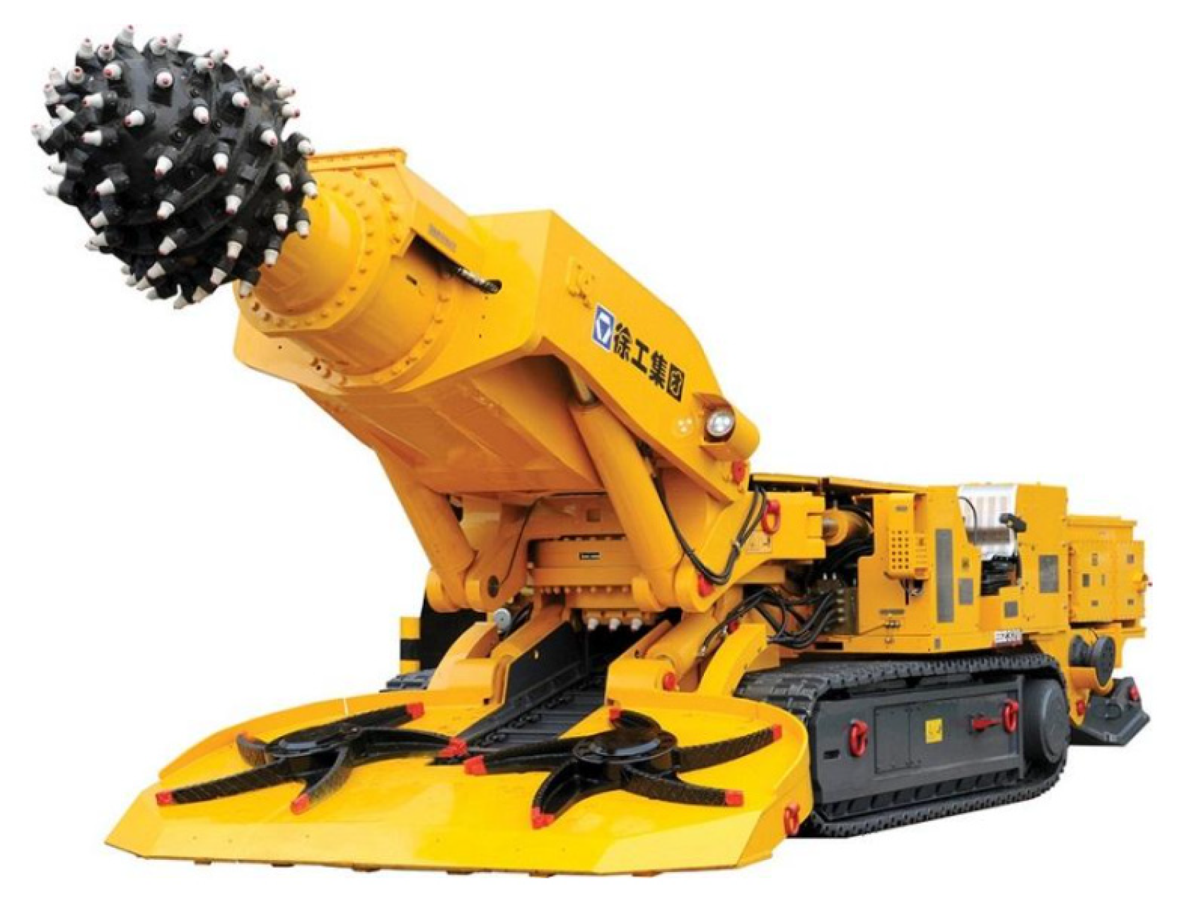
Underground mining of coal accounts for more than 75 percent of China’s current coal production, and the inevitable part of underground mining is the withdrawal of mining equipment when the work is finished [1,2]. A pre-excavation double equipment withdrawal channel (EWC) has two EWCs that are arranged near the stop-production line while preparing the working face: There is a main equipment withdrawal channel (MEWC) and an auxiliary withdrawal channel (AEWC), as shown in Figure 1. The EWC is excavated and formed by using an EBZ135A integrated mechanized roadheader, which made in XuZhou Construction Machinery Group, Xuzhou China (as shown in Figure 2). This type of roadheader has the advantages of fast excavation speed, high efficiency, and small disturbance to surrounding rock. The speed of the equipment’s safe withdrawal is directly related to the profit of a coal mine. To shorten the withdrawal time of the mining equipment and relieve the tension of replacing a working face, more and more coal mines use the layout of pre-excavation EWCs [3].
In the process of underground mining of coal, the front of the working face is always affected by moving abutment pressure [4,5,6]. Advanced microseismic monitoring equipment can obtain the distribution characteristics of the stress field around goaf intuitively [7,8]. Some scholars have studied and determined the variables affecting stress redistribution in the supercritical longwall formation, which is of great significance to the study of the stress field [9,10]. Kang et al. studied abnormal stress under the coal pillar with residual support and obtained its distribution law, which played a major role in the optimization of roadway layout [10]. From another point of view, there is a certain correlation between the coal pillar size and the final mining period of the EWC. By means of numerical calculation, Yang et al. obtained the stress distribution state and plastic zone failure characteristics of roadway-surrounding rocks under different pillar widths. The results show that the stress is in the decreasing zone when the coal pillar is less than 8 m, which is consistent with the distribution of the stress field in the EWC zone during the final mining [11,12]. The research on the influence of rock bolts on roof stability under the action of abutment pressure makes it more clear that bolt support is important for roadway support [13,14,15]. The surrounding rock is affected by the mining and will inevitably undergo deformation and failure, and the related tests also proved the failure rules of rock by abutment pressure [16,17]. Some scholars have obtained the deformation and failure mechanism of the surrounding rock of mining roadways by combining stress distribution under the influence of mining with the failure mode of the roadway [18,19,20]. The study on the mechanical properties of the rock and the boundary equation of the roadway plastic zone under non-constant pressure conditions further reveals the evolution mechanism of the plastic zone under mining [21,22]. Many scholars have studied stability control measures of the surrounding rock [23,24,25,26], such as the surrounding rock control of super-large section tunnels, roadway support in special structural zones, reinforcement support of dynamic pressure roadways, and so on. In addition, numerical simulation analysis plays an increasingly important role in the field of geotechnical engineering [27]. Many scholars have obtained rock failure mechanics theories based on numerical simulation analysis and applied the results to guide engineering practice [28,29,30,31,32].
Previous studies are important for investigating the mechanism of dynamic disasters in the roadway. However, the Lijiahao Coal Mine has not studied the continuous dynamic pressure disturbance of the pre-excavated double EWC. The layout of the pre-excavation double EWC plays a crucial role in production improvement. In the final mining period, the speed of advancement is slowed down, which leads to an increase of mining pressure and a large deformation of the surrounding rock. Faced with such a situation, the distribution characteristics of the moving stress field and the plastic failure mode of the surrounding rock around EWCs is not well understood. Therefore, this paper systematically studied the dynamic evolution law of the regional stress field during the final mining period and the distribution characteristics of the plastic zone during the service period of the EWCs.

2. Engineering Background

2.1. Geological Survey

The Lijiahao Coal Mine is located in the south-central region of the Dongsheng coalfield of Ordos city, south of the Inner Mongolia Autonomous Region in China, with an annual output of 6 Mt. The coal seams in the mining area has the characteristics of shallow burial, complex overlying bedrock structure, thin and soft bedrock. The research object was panel 22116 of the 2-2 middle coal seam in the Lijiahao Coal Mine. The length of the working face is 300 m. The thickness of the coal seam is between 2.88 and 3.21 m, averaging 3.0 m. The average depth of the coal seam is 185 m. The partial roof contains gangue. Generally speaking, the geological conditions are relatively complex. The roof and floor of the coal seam are dominated by mudstone and sandy mudstone. The roof has the characteristics of weak rock, low rock strength, unstable occurrence, and poor stability [33].

2.2. Project Profile

The distance between the MEWC and AEWC of panel 22116 was 25 m. The combined supports of anchor bolts and anchor cables was adopted in the EWC. According to previous engineering experience, the double-row buttress hydraulic support should be installed when the working face is about 300 m away from the MEWC. The MEWC and AEWC sections (width × height) of panel 22216 were 5.2 × 3.0 m and 5.5 × 3.0 m, respectively. The initial support system of the MEWC used anchor cables as “3-2-3” with 2000 mm spacing and 2000 mm row spacing, and the diameter and length of the anchor cables were 17.8 mm and 8000 mm, respectively. The rebar bolts were 20 mm in diameter and 2500 mm in length and were used in the roof with a spacing of 960 mm between bolts and spacing of 1000 mm between rows. The initial support system of the AEWC used anchor cables as “2-2” with 2000 mm spacing and 2000 mm row spacing, and the diameter and length of anchor cables were 17.8 mm and 8000 mm, respectively. The rebar bolts were 20 mm in diameter and 2500 mm in length and were used in the roof in a grid pattern of 1000 mm × 1000 mm. The ribs bolts of both the MEWC and AEWC were used with a spacing of 800 mm between bolts and spacing of 1000 mm between rows. The rib bolts of the MEWC near the working face were fiberglass reinforced plastic (FRP) bolts with 22 mm in diameter and 2000 mm in length and the rib bolts were rod bolts with 16 mm diameter and 2200 mm length. The supporting section is shown in Figure 3.

2.3. Roof Structure Detection

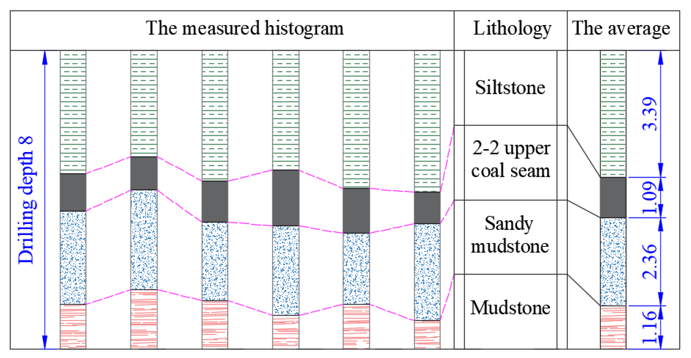
The roof structure and fracture development of the MEWC and AEWC were monitored by using a TYGD10 rock drilling detector when the working face was 200 m away from the MEWC. The borehole was designed to have a depth of 8 m and a diameter of 28 mm. The roof of MEWC and AEWC were evenly arranged with 6 and 4 monitoring boreholes, respectively. The roof structure obtained by borehole detection of the MEWC is shown in Figure 4.
The following information was obtained from the borehole probe. The range of 0–1.16 m above the roof of the MEWC and AEWC is mudstone with little lithologic change. Most roof fractures developed in this section, and it is the main failure zone of the roof. The range of 1.16–3.52 m above the roof is sandy mudstone. The surrounding rock of this section is complete and partially contains coal lines. The range of 3.52–4.61 m above the roof is the 2-2 upper coal seam. The roof above 4.61 m is siltstone with good rock integrity. The representative screenshot of borehole detection is shown in Figure 5. The mechanical parameters of the rock strata of the EWC are shown in Table 1.

3. Theoretical Analysis

3.1. Analysis of the Stress Field in the Mining Area

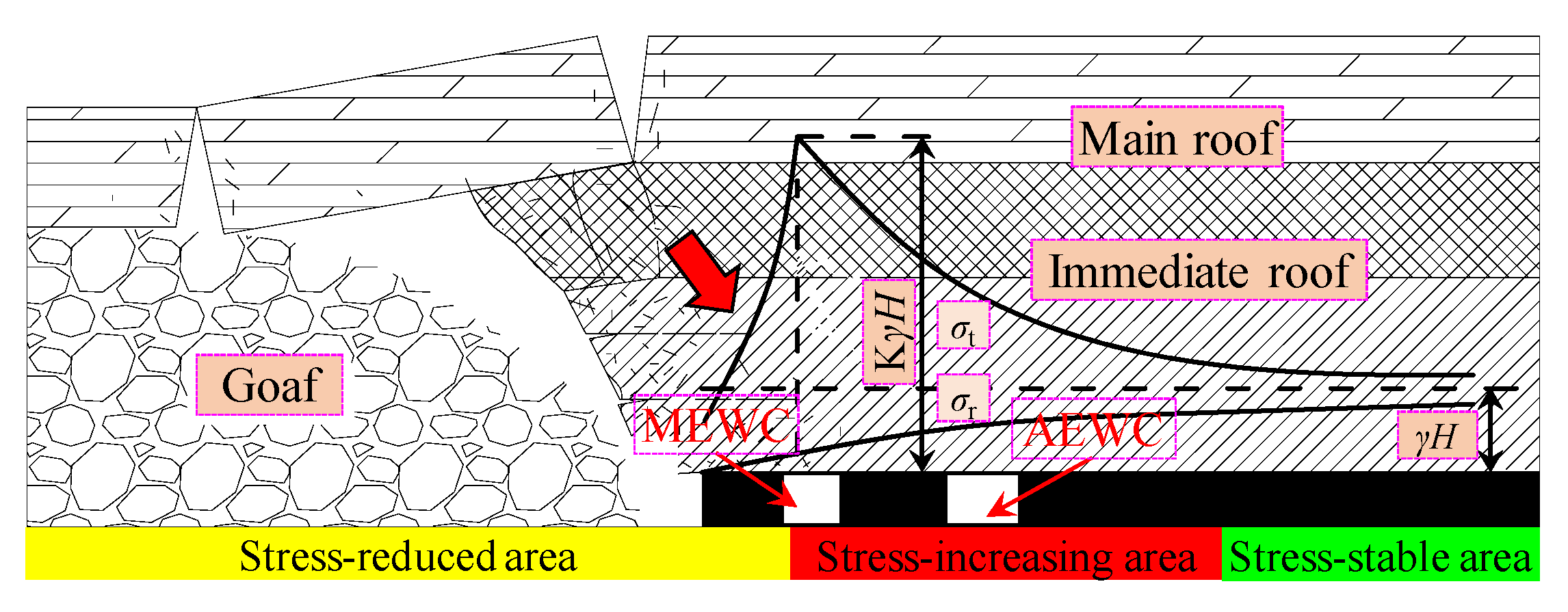
The stress field around the goaf is redistributed after the coal is extracted [34,35], as shown in Figure 6. The tangential stress (σt) increases sharply in front of the working face, then decreases gradually after reaching a peak, and finally tends to the in situ stress. This is consistent with the distribution law of vertical stress [1]. The radial stress (σr) is zero at the free surface of the goaf coal wall and increases gradually along the front of the coal wall. Finally, it also tends to in situ stress, and the overall variation range is small. This is similar to the horizontal stress distribution in mining. According to the existing research results, the coefficient abutment pressure K in front of the working face can reach 3–5 [1,6]. Therefore, the high deviational stress area is formed in a certain range in front of the working face [16].
With the advance of the working face, the immediate roof of the goaf caves in directly and the main roof breaks. It leads to stress release in the upper part of goaf and stress transfer around goaf. Because the collapse and fracture of the overlying strata of the goaf are not synchronous, in other words, the failure of the immediate roof and main roof are asynchronous, the rock blocks are hinged and twisted after the roof is broken, and a huge thrust is formed in the oblique direction of goaf side, as shown in Figure 6. This causes the regional stress field of the surrounding rock to deflect. However, the range of the stress field affected by the above situation is limited. Therefore, the spatial position relationship between the EWC and the goaf dominates the distribution law of the regional stress field and the evolution of the surrounding rock failure mode during final mining.

3.2. Failure Pattern of the Roadway under Asymmetric Pressure

The modified Fenner formula or Kastner formula applies to bidirectional isobaric stress field conditions, i.e., lateral coefficient (λ) is 1. Therefore, the obtained plastic boundary of a circular hole is no longer applicable to the mining roadway [36]. Based on the non-uniform stress environment of mining, the recessive equation of the surrounding rock plastic boundary is obtained by using the theory of elastic mechanics and the Mohr–Coulomb criterion [18,36,37], as shown in Equation (1). The mechanical model of a non-isobaric circular roadway and its plastic zone is shown in Figure 7.
9 ( 1 λ ) 2 ( a R 0 ) 8 [ 12 ( 1 λ ) 2 + 6 ( 1 λ 2 ) cos 2 ( θ α ) ] ( a R 0 ) 6 + { 2 ( 1 λ ) 2 [ cos 2 2 ( θ α ) ( 5 2 sin 2 φ ) sin 2 2 ( θ α ) ] + ( 1 + λ ) 2 + 4 ( 1 λ 2 ) cos 2 ( θ α ) } ( a R 0 ) 4 [ 4 ( 1 λ ) 2 cos 4 ( θ α ) + 2 ( 1 λ 2 ) cos 2 ( θ α ) ( 1 2 sin 2 φ ) 4 P ( 1 λ ) C cos 2 ( θ α ) sin 2 φ ] ( a R 0 ) 2 ( 1 λ ) 2 sin 2 φ ( 1 + λ + 2 C P cos φ sin φ ) 2 = 0
where a is the radius of the roadway; R0 is the boundary radius of the plastic zone; α is the vertical deflection angle of the maximum principal stress; φ and C are the internal friction angle and cohesion of rock media, respectively; and P is the vertical load of the roadway.
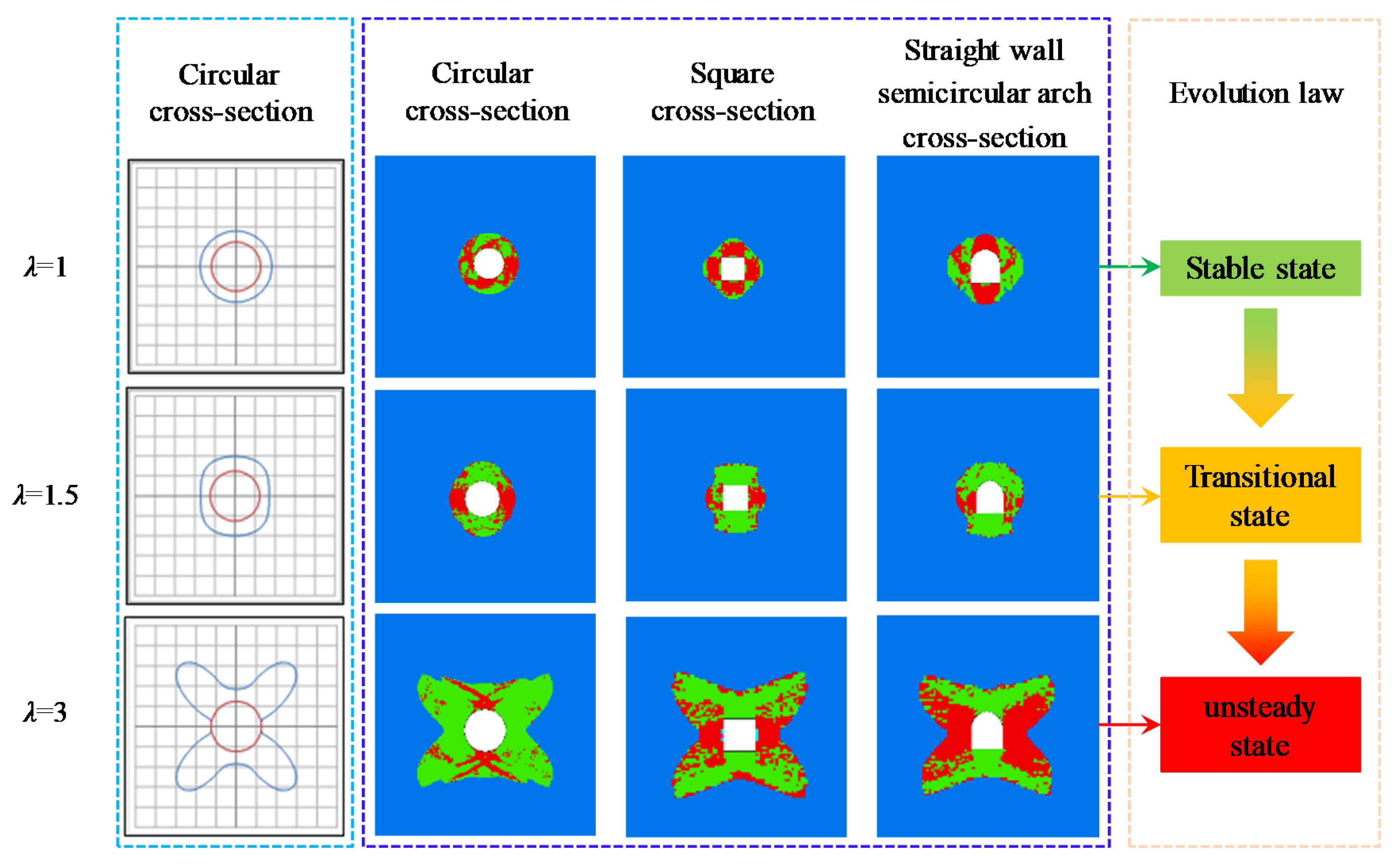
Matlab was used to calculate the plastic zone of the circular roadway using Equation (1), and FLAC3D was used to simulate the shapes of different roadway cross-sections, as shown in Figure 8. All the initial parameters in Figure 8 remain unchanged except stress state and roadway cross-section shape.
The evolution law of the plastic zone of the roadway under different stress states was obtained by theoretical calculation and numerical simulation. It can be seen from Figure 8 that the theoretical calculation is consistent with the numerical simulation results [38]. Under the condition of bidirectional isostatic stress, the plastic zone of the surrounding rock is circular, and the roadway is in a stable state. When there is little difference in pressure values between the two directions, the surrounding rock plastic zone of the roadway evolves into an approximate elliptic shape, and the roadway is in a transitional state. Subsequently, as the pressure ratio of the two directions continues to increase, the boundary of the plastic zone presents a butterfly-shaped distribution, and the roadway is in a state of instability. Different cross-section shapes of roadway have the same response to the same stress state, and there is little difference in the morphology and evolution law of the plastic zone under different cross-sections.

4. Numerical Simulation

FLAC3D is a simulation software based on three-dimensional fast Lagrange difference analysis. It can simulate stress characteristics of the three-dimensional structure of soil and rock, which play an increasingly important role in the field of geotechnical engineering [21,39]. To obtain the stress distribution law in front of the working face during mining, a large FLAC3D numerical model was established. The length, width, and height of the model were 500, 400, and 150 m, respectively. The grid before and after the MEWC was divided into 0.5 m, and the grid in other areas was divided into 1–5 m. The model fixed the lower boundary and the surrounding boundary, and the upper boundary compensated for the 2 MPa vertical stress of the overlying rock. The coefficient of horizontal pressure was 1.2 based on relevant geological data [33,40]. The model calculation was based on the Mohr–Coulomb criterion. The numerical calculation model is shown in Figure 9, and the rock mechanics parameters are shown in Table 1.

4.1. Evolution Law of Mining-Induced Stress during Final Mining

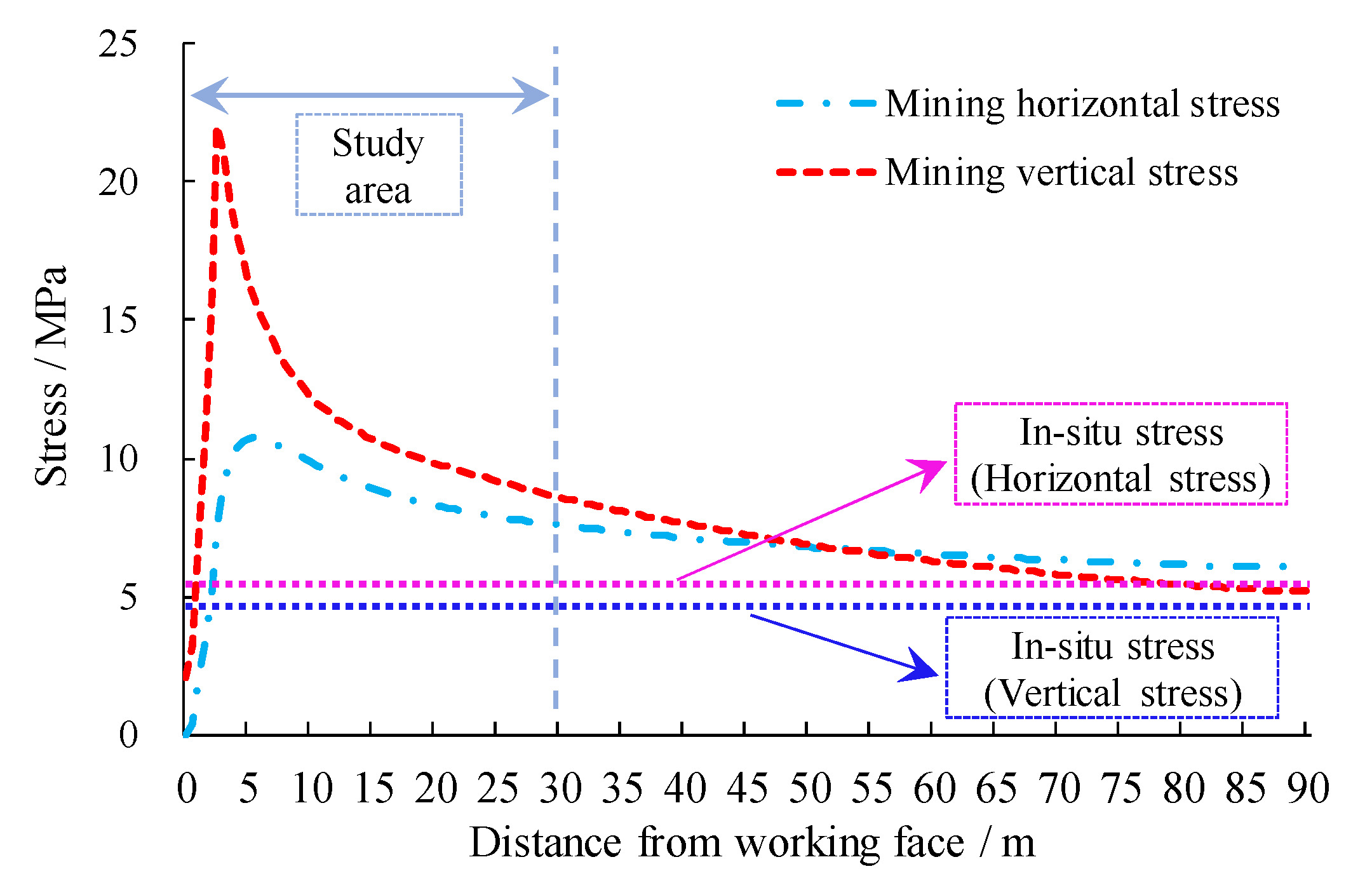
After the initial stress balance of the model, panel 22216 was excavated for 300 m. After the stress was re-balanced, the vertical and horizontal stresses in front of the working face were extracted. The results are shown in Figure 10.
It can be seen from Figure 10 that the vertical and horizontal stresses within 3 m of the working face are lower than the in situ stress. Then, the vertical stress increases sharply and reaches its peak at 4 m in front of the working face. The maximum vertical stress is 22 MPa, which is 4.73 times the in situ stress. Subsequently, the stress decreases, but the decline rate becomes smaller and smaller. The vertical stress at 30 m in front of the working face is 1.82 times the in situ stress, which is 8.45 MPa. The vertical stress at 50 m in front of the working face is 6.71 MPa, which is 1.44 times the in situ stress. The variation trend of horizontal stress is the same as that of the vertical stress, but the stress peak is much smaller than that of the vertical stress. The influence range of the mining stress on panel 22216 is greater than 100 m, but the violent influence range is 30 m.
According to the above analysis, the stress distribution in the final mining period was studied. When the working face is within 30 m of MEWC, the stress distribution is shown in Figure 11. When the working face is 30–20 m away from MEWC, a high-stress concentration occurs in the coal pillar between the working face and MEWC, and the stress is asymmetrical. The stress on the side close to the working face is larger (as shown in Figure 12). There are two stress peaks of vertical stress in the coal pillar between the working face and MEWC, while there was only one peak of the horizontal stress. When the working face is 10 m away from MEWC, the vertical and horizontal stresses in the coal pillar between the working face and MEWC further increase. The stress changes from asymmetric distribution to uniform and the vertical stress is still bimodal. When the working face is 5 m away from the MEWC, the vertical and horizontal stresses in the coal pillar between the working face and the MEWC decrease and present symmetrically distribution with a single peak. In the process of the working face gradually approaching the MEWC from 30 m away, the stress in 25 m coal pillar between the MEWC and AEWC gradually increases, but the distribution law is unchanged. Vertical stress is an asymmetrical bimodal distribution in the coal pillar from beginning to end, but the horizontal stress is asymmetrical and unimodal. The stress on the non-pillar side of the AEWC increases with the approach of the working face.

4.2. Evolution Law of the Plastic Zone during Final Mining

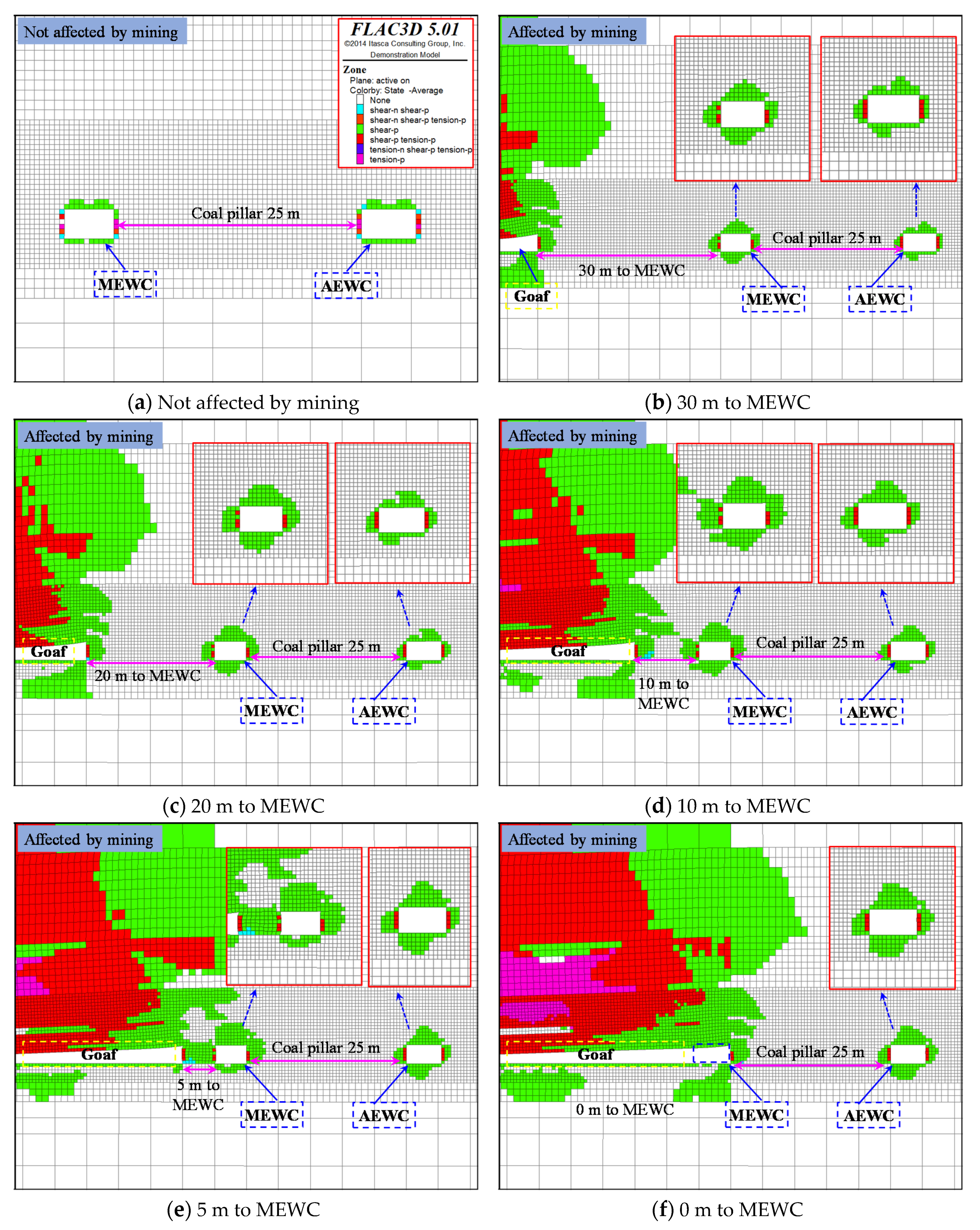
The above numerical model was used to calculate the plastic failure law of the EWCs in different periods, as shown in Figure 13.
Before the EWCs are affected by mining, their plastic zone is uniformly and symmetrically distributed, and the size of the plastic zone is only 1 m, as shown in Figure 13a. When the working face is 30 m away from MEWC, the MEWC is within the scope of working face’s violent influence, and the plastic zone of surrounding rock around the MEWC is expanded. The failure depth of the roof and rib of the MEWC is 2.0 m and 1.5–2.0 m, respectively. The distribution of the plastic zone is no longer in a symmetrical shape. This is mainly affected by the asymmetrically distributed stress. The AEWC is far from the working face and less affected by mining, so the plastic zone of surrounding rock is generally smaller than that of the MEWC, as shown in Figure 13b,c. With the advance of the working face, the size of the plastic zone of the EWCs increases gradually. When the working face is 10 m away from the MEWC, the stress in front of the working face is symmetrically distributed, so the plastic zone distribution of the MEWC evolves into an asymmetrical shape. In addition, due to the influence of huge abutment pressure, the coal body is damaged, and the plastic zone of goaf is connected to the plastic zone of the MEWC, as shown in Figure 13d. When the working face is only 5 m away from the MEWC, the coal pillar between them completely enters the plastic failure state, so the bearing capacity of the coal pillar decreases (Figure 11 and Figure 13e). At this time, the plastic zone of roof and ribs of the MEWC is greater than 3 m (the bolts lay in the plastic zone of surrounding rock), and the ribs and roof plastic zone of the AEWC are 1.5–2 m and 2.5 m, respectively. When the working face is pushed to the MEWC, the roof of the MEWC completely enters a plastic state and the rib plastic zone is greater than 3 m, the plastic zone of roof and ribs in the AEWC are 3 m and 2 m, respectively. The plastic zone of the AEWC is still within the support range of the bolts and cables.

5. Surrounding Rock Control Scheme and Application

5.1. EWC Support Technology during the Final Mining Period

According to numerical simulation, we know that the instability of the surrounding rock during the final mining period starts about 30 m before the connection. In the process of the working face approaching the MEWC, the peaks in the regional vertical stress fields on both sides of the AEWC increase by 4.73 MPa and 3.76 MPa (10.31 MPa→15.04 MPa, 8.27 MPa→12.03 MPa), respectively, while the peaks in the regional vertical stress fields on both sides of the MEWC increase by 14.35 MPa and 12.26 MPa (10.68 MPa→25.03 MPa, 10.92 MPa→23.18 MPa), respectively. The plastic zone of the MEWC changes more during the final mining period, while the plastic zone of the AEWC is always within the function range of the support body. After the working face is pushed to connect with the MEWC, the whole service cycle of the AEWC is about 2–3 weeks.
Based on the above analysis, we allow the AEWC to produce large deformations as long as the roof does not fall during the final mining period. Therefore, during the final mining period, the key point of stability control of the surrounding rock should focus on the MEWC to prevent partial roof collapse and wall caving during the process of withdrawal of the mining equipment.
(1)
Reinforcement support of anchor cable
The short length of the bolts limits the supporting scope during the final mining period. When the plastic zone of the surrounding rock around the MEWC is larger than the length of the bolt, the bolt cannot effectively control the displacement of the shallow surrounding rock, but also produces overall displacement within the shallow surrounding rock [15]. Therefore, the solid coal rib of the MEWC should be strengthened. In this way, the shallow failure of the surrounding rock can be anchored in the deep stable area to avoid wall collapsing.
With the working face gradually approaching the MEWC, the plastic zone of the roof gradually expands and finally completely fails, which leads to instability of the surrounding rock. Therefore, high-extension anchor cables should be strengthened before they are affected by mining, the roof rock strata should be combined as a common carrier, and the residual bearing capacity of the rock strata within the anchorage range should be improved while the roof deformation is allowed. This effectively prevents the failure of hydraulic supports caused by partial roof collapse [41,42]. The reinforcement support scheme of the MEWC is shown in Figure 14.
(2)
Support of buttress hydraulics
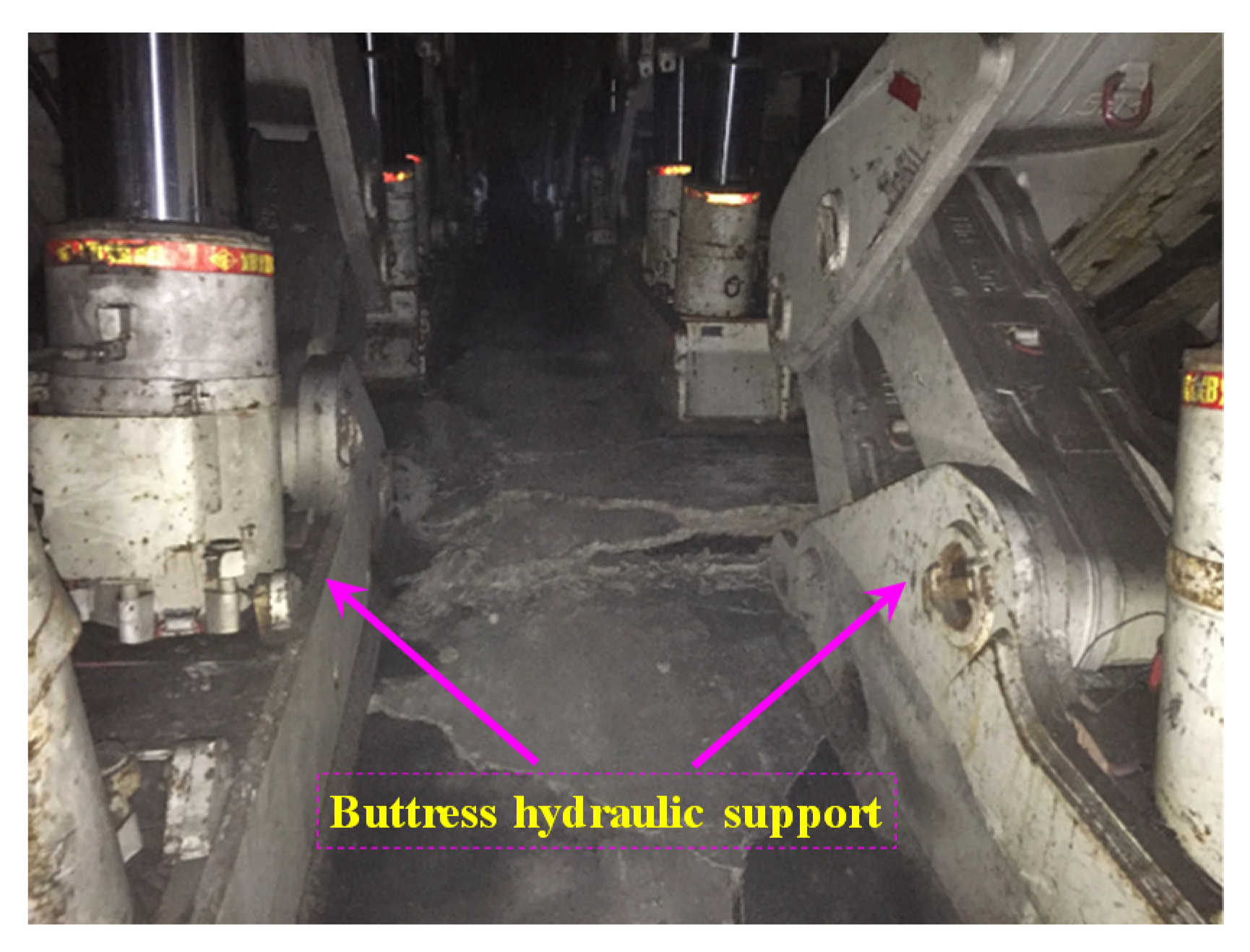
To avoid severe roof sag of the MEWC caused by severe mining pressure during the final mining period, buttress hydraulic supports are installed in the MEWC before it is affected by mining. The buttress hydraulic supports adopt an installation mode of double-row parallel, as shown in Figure 15. A pair of supports were also installed in the connection roadway near the MEWC. It is required that the distance between the working face and the MEWC should be greater than 100 m when the buttress hydraulic support installation is completed. In this way, support resistance can be provided in time to avoid large-scale separation failure of the surrounding rock that is affected by mining.

5.2. Field Monitoring of the MEWC

During the final mining period, anchor cables reinforcement and buttress hydraulic supports were adopted. The engineering practice proves that the EWCs are stable and the withdrawal of the working face is successful. During the withdrawal the roof did not fall and the walls did not cave in. Pressure monitoring during the final mining period is shown in Figure 16 and Figure 17 below.
(1)
Working resistance monitoring of buttress hydraulic supports
When the working face was 1 m away from the MEWC of 22116, the working resistance monitoring of the two-row buttress hydraulic supports are shown in Figure 16. From this, it can be concluded that the working resistance of buttress hydraulic supports near the working face are generally greater than that near the coal pillar. The average working resistance of buttress hydraulic supports close to the working face was 37.2 MPa, while close to the coal pillar it was 25.1 MPa. During the final mining period, the buttress hydraulic supports provided stable working resistance, no failure occurred in the MEWC, and the stability of EWCs was good.
(2)
Surface displacement of the roadway
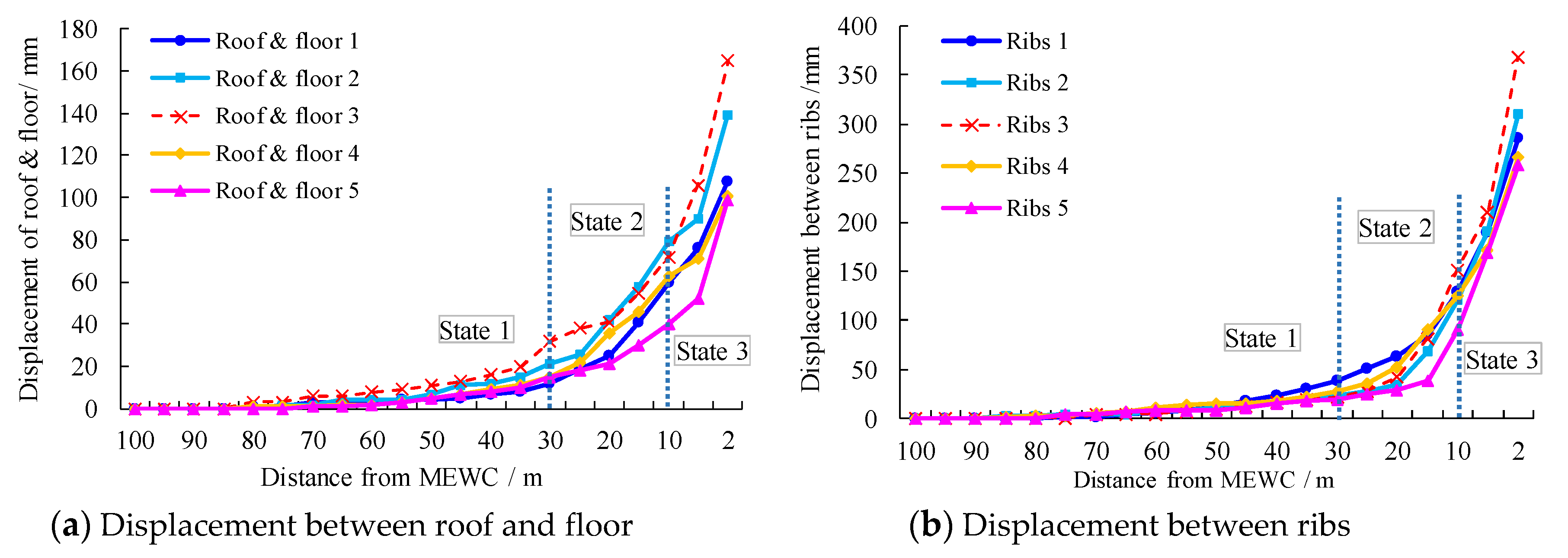
Five observation points were evenly arranged in the MEWC, and observation started when the working face was 100 m away from the MEWC. The monitoring data are shown in Figure 17. According to the figure, the deformation of the MEWC during the final mining period was divided into three stages. They were a stable stage (state 1), slow deformation stage (state 2), and severe deformation stage (state 3. In other words, if the distance between the working face and the MEWC is greater than 30 m, it is state 1; if the distance between the working face and the MEWC is 10–30 m, it is state 2; and if the distance between the working face and the MEWC is less than 10 m, it is state 3. According to the monitoring data, the average deformation ratio of the roof and floor is 15.5%, 35.8%, and 48.7%, in states 1, 2, and 3, respectively, and the average deformation ratio of ribs is 8.9%, 32.7%, and 58.4%, respectively. Although the MEWC had a large deformation during withdrawal, there was no roof fall or wall caving, and the roadway had good stability.

6. Discussion

With the continuous excavation of the working face, the abutment pressure in front of the working face is constantly moving forward, which is the moving abutment pressure. Compared with the reserved roadway, which is only affected by the fixed abutment pressure from the side of the goaf, the EWCs in front of the working face are affected by the moving abutment pressure during the final mining period. As a result, the stress distribution and the shape of plastic zone of the EWCs are constantly changing during the final mining period.
Based on the voussoir beam theory, this paper briefly analyzed the cause of the abutment pressure around goaf. The stress field of the surrounding rock under abutment pressure is non-uniformly distributed. Therefore, based on elastic mechanics, the formula of the roadway’s plastic zone under the influence of a non-uniform stress field was deduced by using the Mohr–Coulomb failure criterion. The theoretical formula calculation results are in good agreement with the FLAC3D calculation results. The numerical simulation results show that the formula has guiding significance for different cross-section shapes of roadways. The plastic zone evolution diagram of the roadway is shown in Figure 18. The failure of the surrounding rock under different stress states occurs within a mile.
We used FLAC3D to numerically simulate the evolution of the regional stress field and the distribution characteristics of the plastic zone around the EWCs during the final mining period. We found that the stress disturbance on the MEWC is more complicated. The stress on the goaf side of the MEWC gradually evolved from bimodal symmetrical distribution to bimodal asymmetrical distribution, then to bimodal symmetrical distribution, and finally to a unimodal symmetrical distribution. However, the stress on the other side that is close to the AEWC always presented a bimodal asymmetric distribution, only the stress value increased. The shape and size of the plastic zone of the EWCs also developed, and finally presented butterfly-shaped distribution. The results of the numerical simulation were highly consistent with the butterfly shaped plastic zone theory proposed by us. The surrounding rock stability control scheme based on this theory also effectively ensured the smooth progress of the project.
Butterfly-shaped plastic zone theory can better explain the large deformation of the surrounding rock, coal, and gas outburst, and rockburst in mining engineering. However, the limited accuracy of the detection equipment meant it was not possible to detect the actual shape and size of the plastic zone of the mine’s surrounding rock. In terms of roadway support, the author conducted some theoretical studies on the mechanisms of the anchor cable support. In roadway engineering, the anchor cable support will not play a significant role in the improvement of the surrounding rock plastic zone and the excavation stress field [16,43], as shown in Figure 19. However, the laboratory mechanism research of anchor cable support still needs further study.

7. Conclusions

1
The extraction of coal leads to a stress superposition of the surrounding rock around the goaf, and the maximum stress concentration coefficient can reach 3~5. Under such a non-uniform stress environment, the plastic zone of the surrounding rock is no longer a circular distribution but gradually evolves into a butterfly shape with the increase of the lateral pressure coefficient. The different cross-section shapes of the roadway do not affect the final plastic zone shape.
2
The stress environment of the MEWC is more complex than that of the AEWC. The stress peak value on the side close to the working face of the MEWC first increases and then decreases, and its distribution features are first asymmetric and then symmetric. Meanwhile, the stress on the side close to the coal pillar is always asymmetrical and the stress value keeps increasing. The stress distribution around the AEWC remains almost unchanged; the value increases only slightly.
3
When the MEWC is not affected by mining, the plastic zone around it is only 1 M and symmetrically distributed. With the advance of the working face, the EWC plastic zone gradually expands and presents an asymmetric distribution. Finally, the plastic zone depth of the MEWC is greater than the length of the supporting body, and the surrounding rock tends to be unstable.
4
After analyzing the damage characteristics of the EWCs during the final mining, the use characteristics of EWCs were further analyzed. The service cycle of the EWCs is short, only about one month. Therefore, we proposed a stability control scheme of the MEWC’s surrounding rock, i.e., the reinforcement technologies of anchor cables and buttress hydraulic supports. After the field application, there was no roof fall or wall caving, and the equipment withdrawal process was successful.

Author Contributions

Conceptualization, C.L. and X.L.; Methodology, C.L. and X.G.; Investigation, C.L. and X.L.; Writing, C.L. and X.G.; review and editing, N.M. All authors have read and agreed to the published version of the manuscript.

Funding

This work was partially supported by the National Natural Science Foundation of China (Grant No. 52004289) and the National Key Research and Development Program (Grant No. 2016YFC0600708).

Conflicts of Interest

The authors declare no conflict of interest.

References

  1. Qian, M.G.; Shi, P.W.; Xu, J.L. Mining Pressure and Strata Control; China University of Mining and Technology Press: Xuzhou, China, 2010. [Google Scholar]
  2. Wang, B.N. Mechanism of Surrounding Rock Deformation and Failure and Control. Method Research in Retracement Roadway; Xi’an University of Science and Technology: Xi’an, China, 2017. [Google Scholar]
  3. Ti, Z.Y.; Zhang, F.; Pan, J. Accident analysis of bracket and roof collapse before retracement under high face mining. Chin. J. Geol. Hazard. Control. 2019, 30, 78–83. [Google Scholar] [CrossRef]
  4. Diederichs, M.S.; Kaiser, P.K. Stability of large excavations in laminated hard rock masses: The voussoir analogue revisited. Int. J. Rock Mech. Min. 1999, 36, 97–117. [Google Scholar] [CrossRef]
  5. Shabanimashcool, M.; Li, C.C. Vertical stress changes in multi-seam mining under supercritical longwall panels. Int. J. Rock Mech. Min. 2013, 106, 39–47. [Google Scholar] [CrossRef]
  6. Ren, Y.F.; Ning, Y. Changing Feature of Advancing Abutment Pressure in Shallow Long Wall Working Face. J. China Coal Soc. 2014, 39, 38–42. [Google Scholar] [CrossRef]
  7. Zhang, W.L.; Qu, X.C.; Li, C.; Wu, Z. Fracture analysis of multi-hard roofs based on microseismic monitoring and control techniques for induced rock burst: A case study. Arab. J. Geosci. 2019, 12, 784. [Google Scholar] [CrossRef]
  8. Zhang, W.L.; Ma, N.; Ma, J.; Li, C.; Ren, J. Mechanism of Rock Burst Revealed by Numerical Simulation and Energy Calculation. Shock Vib. 2020, 2020, 8862849. [Google Scholar] [CrossRef]
  9. Cohen, T.; Masri, R.; Durban, D. Analysis of circular hole expansion with generalized yield criteria. Int. J. Solids Struct. 2009, 46, 3643–3650. [Google Scholar] [CrossRef] [Green Version]
  10. Kang, J.Z.; Shen, W.L.; Bai, J.B.; Yan, S.; Wang, X.Y.; Li, W.F.; Wang, R.F. Influence of abnormal stress under a residual bearing coal pillar on the stability of a mine entry. Int. J. Min. Sci. Technol. 2017, 27, 945–954. [Google Scholar] [CrossRef]
  11. Yang, R.S.; Zhu, Y.; Li, Y.L.; Li, W.Y.; Lin, H. Coal pillar size design and surrounding rock control techniques in deep longwall entry. Arab. J. Geosci. 2020, 13, 1–14. [Google Scholar] [CrossRef]
  12. Yang, K.; Gou, P.F. Research on Reasonable Width of Coal Pillars in High Strength Mining Roadway in Wantugou Mine. Geotech. Geol. Eng. 2020, 2020, 1–9. [Google Scholar] [CrossRef]
  13. Osgoui, R.R.; Unal, E. An empirical method for design of grouted bolts in rock tunnels based on the Geological Strength Index (GSI). Geotech. Geol. Eng. 2009, 107, 154–166. [Google Scholar] [CrossRef]
  14. Ghabraie, B.; Ren, G.; Zhang, X.Y.; Smith, J. Physical modelling of subsidence from sequential extraction of partially overlapping longwall panels and study of substrata movement characteristics. Int. J. Coal Geol. 2015, 140, 71–83. [Google Scholar] [CrossRef]
  15. Kang, H.P.; Li, J.Z.; Yang, J.H.; Gao, F.Q. Investigation on the Influence of abutment pressure on the stability of rock bolt reinforced roof strata through physical and numerical modeling. Rock Mech. Rock Eng. 2017, 50, 387–401. [Google Scholar] [CrossRef]
  16. Li, C.; Zhang, W.L.; Wang, N.; Hao, C. Roof stability control based on plastic zone evolution during mining. J. Min. Saf. Eng. 2019, 36, 753–761. [Google Scholar] [CrossRef]
  17. Ren, F.Q.; Zhu, C.; He, M.C. Moment tensor analysis of acoustic emissions for cracking mechanisms during schist strain burst. Rock Mech. Rock Eng. 2020, 53, 153–170. [Google Scholar] [CrossRef]
  18. Ma, N.J.; Li, J.; Zhao, Z.Q. Distribution of the deviatoric stress field and plastic zone in circular roadway surrounding rock. J. China U. Min. Techno. 2015, 44, 206–213. [Google Scholar] [CrossRef]
  19. Li, J.; Ma, N.J.; Ding, Z.W. Heterogeneous large deformation mechanism based on change of principal stress direction in deep gob side entry and control. J. Min. Saf. Eng. 2018, 35, 670–676. [Google Scholar] [CrossRef]
  20. Yan, H.; He, F.L.; Yang, T.; Li, L.Y.; Zhang, S.B.; Zhang, J.X. The mechanism of bedding separation in roof strata overlying a roadway within a thick coal seam: A case study from the Pingshuo Coalfield, China. Eng. Fail. Anal. 2015, 62, 75–92. [Google Scholar] [CrossRef]
  21. Molladavoodi, H.; Rahmati, M. Dilation angle variations in plastic zone around tunnels in rocks-constant or variable dilation parameter. J. Cent. South. Univ. 2018, 25, 2550–2566. [Google Scholar] [CrossRef]
  22. Wang, W.J.; Dong, E.Y.; Yuan, C. Boundary equation of plastic zone of circular roadway in non-axisymmetric stress and its application. J. China Coal Soc. 2019, 44, 105–114. [Google Scholar] [CrossRef]
  23. Chen, H.; Jiang, Y.D.; Deng, D.X.; Shao, M.M. Study on deformation characteristics and support optimization of weak surrounding rock in fault zone. J. Min. Sci. Technol. 2018, 3, 543–552. [Google Scholar] [CrossRef]
  24. Yang, J.; Gao, Y.B.; Liu, S.Q.; Peng, Y.H. Study on failure mechanism and control techniques of the preparation roadway induced by dynamic mining disturbance. J. Min. Sci. Technol. 2018, 3, 451–460. [Google Scholar] [CrossRef]
  25. Gao, X.C.; Luan, Y.C.; Hu, C.; Lu, W.; Sun, H. Study on bearing mechanism and coupling mechanism of steel arch-concrete composite structure of initial support system of large section tunnel. Geotech. Geol. Eng. 2019, 37, 4877–4887. [Google Scholar] [CrossRef]
  26. Pan, R.; Wang, Q.; Jiang, B.; Li, S.C. Model test on failure and control mechanism of surrounding rocks in tunnels with super large sections. Arab. J. Geosci. 2019, 12, 1–17. [Google Scholar] [CrossRef]
  27. Yang, H.Z.; Guo, Z.; Chen, D.; Wang, C.; Zhang, F.; Du, Z. Study on Reasonable Roadway Position of Working Face under Strip Coal Pillar in Rock Burst Mine. Shock Vib. 2020, 2020, 8832791. [Google Scholar] [CrossRef]
  28. Pellet, F.; Roosefid, M.; Deleruyelle, F. On the 3D numerical modelling of the time-dependent development of the damage zone around underground galleries during and after excavation. Tunn. Undergr. Sp. Tech. 2009, 24, 665–674. [Google Scholar] [CrossRef]
  29. Bai, Q.X.; Tu, S.H.; Wang, F.T. Field and numerical investigations of gateroad system failure induced by hard roofs in a longwall top coal caving face. Int. J. Coal Geol. 2017, 173, 176–199. [Google Scholar] [CrossRef]
  30. Jiang, L.S.; Wang, P.; Zhang, P.P. Numerical analysis of the effects induced by normal faults and dip angles on rock bursts. C. R. Mec. 2019, 345, 690–705. [Google Scholar] [CrossRef]
  31. Jia, H.S.; Wang, L.Y.; Fan, K.; Peng, B.; Pan, K. Control technology of soft rock floor in mining roadway with coal pillar protection: A case study. Energies 2019, 12, 3009. [Google Scholar] [CrossRef] [Green Version]
  32. Li, A.; Liu, Y.; Dai, F.; Liu, K.; Wei, M.D. Continuum analysis of the structurally controlled displacements for large-scale underground caverns in bedded rock masses. Tunn. Undergr. Sp. Tech. 2020, 97, 103288. [Google Scholar] [CrossRef]
  33. Yang, G.R. Study on the Roof Caving Prediction Principle and Method of the Hazard. Area at Starting Cut Lijiahao Mine; China University of Mining and Technology (Beijing): Beijing, China, 2013. [Google Scholar]
  34. Kaiser, P.K.; Yazici, S.; Maloney, S. Mining-induced stress change and consequences of stress path on excavation stability—A case study. Int. J. Rock Mech. Min. 2001, 38, 167–180. [Google Scholar] [CrossRef]
  35. Rezaei, M.; Hossaini, M.F.; Majdi, A. Development of a time-dependent energy model to calculate the mining-induced stress over gates and pillars. J. Rock. Mech. Geotech. 2015, 7, 306–317. [Google Scholar] [CrossRef]
  36. Zhao, Z.Q. Mechanism of Surrounding Rock Deformation and Failure and Control. Method Research in Large Deformation Mining Roadway; China University of Mining and Technology (Beijing): Beijing, China, 2014. [Google Scholar]
  37. Zhao, Z.Q.; Ma, N.J.; Liu, H.; Guo, X.F. A butterfly failure theory of rock mass around roadway and its application prospect. J. China Univ. Min. Technol. 2018, 47. [Google Scholar] [CrossRef]
  38. Guo, X.F.; Zhao, Z.Q.; Gao, X.; Wu, X.Y.; Ma, N.J. Analytical solutions for characteristic radii of circular roadway surrounding rock plastic zone and their application. Int. J. Min. Sci. Technol. 2019, 29, 263–272. [Google Scholar] [CrossRef]
  39. Liang, P.; Gao, Y.T. Numerical investigation on cracking behavior of granite with intersecting two-flaws: A flat-joint modeling method. Lat. Am. J. Solids Struct. 2020, 17, 1–14. [Google Scholar] [CrossRef]
  40. Liu, J. In-situ stress measurements and study on distribution characteristics of stress fields in underground coal mines in yitai mining area. J. China Coal Soc. 2011, 36, 562–566. [Google Scholar] [CrossRef]
  41. Jia, H.S.; Ma, N.J.; Zhu, K. Mechanism and control method of roof fall resulted from butterfly plastic zone penetration. J. China Coal Soc. 2016, 41, 1384–1392. [Google Scholar] [CrossRef]
  42. Lin, C.D.; Lu, S.L.; Shi, Y.W. Study on supporting effect of soft roof bolt in coal roadway. J. China Coal Soc. 2000, 25, 482–485. [Google Scholar] [CrossRef]
  43. Li, C.; Wu, Z.; Zhang, W.L.; Sun, Y.H.; Zhu, C.; Zhang, X.H. A case study on asymmetric deformation mechanism of the reserved roadway under mining influences and its control techniques. Geomech. Eng. 2020, 22, 449–460. [Google Scholar] [CrossRef]
Figure 1. Schematic diagram of the pre-excavation equipment withdrawal channels (EWCs). MEWC: main equipment withdrawal channel; AEWC: auxiliary equipment withdrawal channel.
Energies 13 06368 g001
Figure 2. EBZ135A integrated mechanized roadheader.
Energies 13 06368 g002
Figure 3. Support profile of the EWCs (mm).
Energies 13 06368 g003
Figure 4. Detection results of the MEWC roof structure (m).
Energies 13 06368 g004
Figure 5. Borehole imaging screenshot.
Energies 13 06368 g005
Figure 6. Abutment pressure model in front of the working face.
Energies 13 06368 g006
Figure 7. Mechanical model of the circular roadway.
Energies 13 06368 g007
Figure 8. Evolution of the rock failure patterns surrounding the roadway.
Energies 13 06368 g008
Figure 9. 3D view of the numerical model.
Energies 13 06368 g009
Figure 10. Mining stress distribution characteristics.
Energies 13 06368 g010
Figure 11. Law of stress evolution during final mining.
Energies 13 06368 g011
Figure 12. The vertical stress nephogram.
Energies 13 06368 g012
Figure 13. Evolution of the plastic zone.
Energies 13 06368 g013
Figure 14. Reinforcement support scheme.
Energies 13 06368 g014
Figure 15. Photos of buttress hydraulic supports on site.
Energies 13 06368 g015
Figure 16. Working resistance of buttress hydraulic supports.
Energies 13 06368 g016
Figure 17. The curve of displacement monitoring.
Energies 13 06368 g017
Figure 18. Relationship between mining stress and the plastic zone.
Energies 13 06368 g018
Figure 19. Vertical stress distribution of the roadway with and without support.
Energies 13 06368 g019
Table 1. Lithology and rock mechanics parameters.
LithologyDensity
(kg/m 3)
Bulk Modulus
/103 MPa
Shear Modulus
/10 3 MPa
Friction
Angle/(°)
Cohesion
/MPa
Tensile
Strength/MPa
Fuyan25003.181.6322.211.22
Sandy-mudstone 524003.681.8352.631.13
Siltstone 226002.921.9311.521.08
Fine-sandstone 325002.521.7342.531.17
Siltstone 126003.911.9301.941.13
2-2 upper-coal14001.890.6251.560.93
Sandy-mudstone 422002.761.6321.721.26
Mudstone23001.760.8271.440.86
2-2 middle-coal15001.890.6251.520.93
Sandy-mudstone 324003.812.2301.831.02
Fine-sandstone 224003.661.8281.761.15
Sandy-mudstone 225002.532.7322.111.21
Fine-sandstone 124003.681.8311.921.12
Sandy-mudstone 125002.531.7332.521.06
Publisher’s Note: MDPI stays neutral with regard to jurisdictional claims in published maps and institutional affiliations.