Article

In Situ Monitoring of Drying Process of Masonry Walls

by
Łukasz Cieślikiewicz
,
Piotr Łapka
* and
Radosław Mirowski
Institute of Heat Engineering, Faculty of Power and Aeronautical Engineering, Warsaw University of Technology, 21/25 Nowowiejska St., 00-665 Warsaw, Poland
*
Author to whom correspondence should be addressed.
Energies 2020, 13(23), 6190; https://doi.org/10.3390/en13236190
Submission received: 4 November 2020 / Revised: 17 November 2020 / Accepted: 18 November 2020 / Published: 25 November 2020

Abstract

:
The in situ hygro-thermal behavior of a wet masonry wall during its drying process is presented in this paper. The considered wall is a part of a basement of a historic building that was subjected to renovation works. The building is located in the City of Łowicz (Poland). The drying process was implemented by applying the thermo-injection method and a novel prototype of the drying device used for this method. The dedicated acquisition system was developed to in situ monitor parameters of the drying process. The air temperature and relative humidity in various locations in the basement, temperatures and moisture contents at several points of the wet wall as well as the electrical parameters of the drying device were registered. Based on variations of the monitored parameters, the hygro-thermal behavior of the wall during drying was studied. After 6 days of drying, the wall temperature in the drying zone was increased to approximately 40–55 °C, while the moisture content was reduced to the mean level of 3.76% vol. (2.35% wt.). These wall parameters allowed for effective impregnation of the wall with the hydrophobic silicone micro-emulsion, which created horizontal and vertical waterproofing. Moreover, the specific energy consumption during the drying process defined as energy consumption divided by the mean volumetric moisture content drop (MC) between the initial and final state in the wall and by the length of the dried wall section was estimated to be 11.08 kWh/MC%/m.

1. Introduction

In old and historical buildings, the problem of rising moisture (groundwater) in masonry walls is very common. The lack or incorrect implementation or worn out horizontal and vertical damp-proof insulation in the underground parts of buildings are the sources of the dampness problem. The excessive moisture in the masonry walls in the basement may results in severe damage, e.g., material degradation, dissolution of compounds, salt migration and crystallization, cracking and spalling. Moreover, the dampness may penetrate higher parts of buildings, which causes damage in plasters, facings or precious ornaments covering the walls. These effects are accompanied by serious deterioration of mechanical and hygro-thermal properties of the material of walls as well as sanitary conditions inside the building. Therefore, when excessive moisture is detected in the building due to capillary rising from the ground, retrofitting must be conducted. One of the methods of historic building renovation is drying damp masonry walls in the basement and ensuring new horizontal and vertical waterproofing. Other renovation activities should also be planned [1].
In order to correctly dry masonry walls, knowledge about the hygro-thermal phenomena in building elements and in the surrounding humid air is crucial. However, the transport of moisture in porous building structures is a very complex process which is influenced by many factors. The investigation of the moisture and temperature behavior during the drying of masonry walls may be helpful in understanding and properly designing this process. This is also very important for the efficiency optimization of the drying process, which is highly energy consuming.
Most of the research presented in the literature has been devoted to the problem of monitoring and analyzing the moisture content and moisture transfer in various elements of buildings, e.g., in masonry walls or floors, during different periods of their normal/standard use. In situ moisture monitoring is very important for both the diagnosis of building problems and the acquisition of knowledge on the moisture transport to predict building performance.
Several researches related to development and/or application of in situ monitoring techniques and systems for the investigation of moisture behavior in the different elements of buildings were identified. These systems were based on different techniques [2]. For example, Válek et al. [3] analyzed the drying behavior of laboratory models of masonry walls made of fired clay brick, sandstone and spongilite that were flooded. The following techniques were investigated: infrared thermography, complex resistivity, ground penetrating radar and ultrasonics. The measured moisture contents were compared with those obtained with the gravimetric method. Good qualitative matching of the results obtained, applying different non-destructive testing methods, was observed. Fidríková et al. [4] developed a new sensor principle for moisture monitoring in the masonry walls. This system was based on changes in the thermal conductivity of porous structures when they were filled with moist air, water or ice depending on the existing thermodynamic conditions in the building. The system was placed in the northern, southern and western masonry wall of St. Martin’s Cathedral tower in Bratislava and tested in situ. Zegowitz et al. [5] investigated drying process of different components and layers of the floor construction and walls. They built a large-scale laboratory tests site with four rooms, each with three types of masonry walls made of internally insulated clay bricks and a typical floor for intermediate storeys. Rooms were located within a climate simulator, and water damage was artificially simulated. A measuring system with more than 300 sensors for moisture content, relative humidity and temperature accompanied by thermography was applied to monitor the drying behavior. They demonstrated the advantages and disadvantages of the tested drying systems, i.e., underfloor drying equipment, infrared heating panels and lance wall drying system. Walker and Pavía [6] studied the in situ moisture behavior of a solid brick wall with different internal insulations of varying thermal and moisture characteristics. The measurements were carried out over a two-and-a-half-year period. They monitored the internal temperature and relative humidity near the internal interface between the insulation and solid brick wall. They found that the vapor permeability of the insulation had a great impact on the moisture behavior of walls. Rymarczyk et al. [7] proposed a system for the analysis of moisture content in walls, including historical buildings, which was based on a hybrid tomography, original measurement sensors and a solution of the inverse problems. This system was able to estimate moisture not only on the surface but also on the inside of the wall. Cieślikiewicz et al. [8] developed an experimental stand for the investigation of the drying process in a model of a brick wall (small scale). The stand was equipped with a precise platform balance to measure the total moisture content in the specimen as well as several time-domain reflectometry (TDR) probes to register the local variations of the volumetric moisture content and resistance temperature detectors (RTD) to measure the temperature changes in a test wall. They presented preliminary results of the monitoring of the drying process of a small wall. Hoła and Sadowski [9] developed the method of neural identification of the moisture content in saline brick walls in historic buildings. The method utilized artificial neural networks, which were trained on a set of data obtained using non-destructive methods and collected on a selected representative group of masonry historic buildings from different historical periods. The data set contained two parameters that described the moisture content assessed by the dielectric and microwave methods and three parameters that described the concentration of basic salts in the damp walls assessed by the semi-quantitative method and the mass moisture content estimated by the gravimetric method. The test that was carried out showed that it is possible to reliably identify the moisture content of saline brick walls using the proposed approach without the necessity of interference in the wall structure. Next, the method proposed in [9] was successfully validated by investigating the moisture content in two historic buildings other than those used for the learning and testing of the artificial neural networks [10]. Orr et al. [11] evaluated the performance of microwave sensors and radar for monitoring the moisture movement in the masonry walls subjected to wind-driven rain. Tests were carried out for two objects, i.e., the laboratory model of a granite wall and a tower constructed from sandstone, which were typical for Oxford in England and Edinburgh in Scotland, respectively. It was demonstrated that both measurement techniques are useful for monitoring the moisture in stone masonry systems. Recently, Hoła [12] proposed an original methodology of testing the moisture content of brick walls in buildings. The methodology was developed based on the investigation of many excessively wet buildings erected in various historical periods. It used various non-destructive methods for the measurements of moisture content in walls. The methodology was tested on a facility from the 14th century. It was concluded that it is important to not only determine the moisture content, but also to find its distribution along the length and height of individual walls. The heat and moisture behavior of the whole buildings, elements of the buildings and building materials was also investigated by applying numerical modeling. For example, Cabrera et al. [13] simulated two conventional tests used for the characterization of the hygro-thermal behavior of heritage elements to check the capacity and quality of the moisture transfer simulation with the new functions, i.e., with the hydraulic conductivity and diffusion resistance factor. These tests were carried out using a moisture transport module implemented in COMSOL Multiphysics. Belleghem et al. [14] developed a three-dimensional (3D) heat and mass transfer model which allowed for simultaneously accounting for both the convective conditions surrounding a porous material and the heat and moisture transport in the porous material. The model was implemented in the ANSYS Fluent software and was validated for the case of convective drying of a saturated ceramic brick. In [15], two models of heat and moisture transfer in building materials, i.e., the equilibrium and non-equilibrium one, have been proposed, and their accuracies were verified. As indicated, these models may be applied for analysis of hygro-thermal behavior during drying of masonry walls including historical buildings. However, to carry out reliable numerical simulations, detailed knowledge about hygro-thermal properties of building materials is crucial. Luckily, such data may be found in the literature [16,17].
The quoted investigations dealt mainly with moisture monitoring in buildings or with the simulation of hygro-thermal behavior of building elements under their normal/standard use. There is a lack of studies related to the analysis of the hygro-thermal behavior of the masonry wall during its drying in the real scale. Moreover, there is no in situ analysis of power consumption during the drying process of real masonry walls. These gaps in the knowledge are filled in this work.
The paper is organized as follows. First, descriptions of the renovated building, drying and waterproofing techniques as well as measurement system are given. Next, the results of monitoring of drying process are shown and discussed. Finally, the study is summarized.

2. Materials and Methods

2.1. Renovated Building

The building under consideration is shown in Figure 1. It is a former monastic custody located in the city of Łowicz in Poland, which was built at the end of the 18th century. Today, it is a rectory. The building belongs to a group of historic buildings located at the northern frontage of the Old Market Square in Łowicz. The facility is entered in the provincial register of monuments.
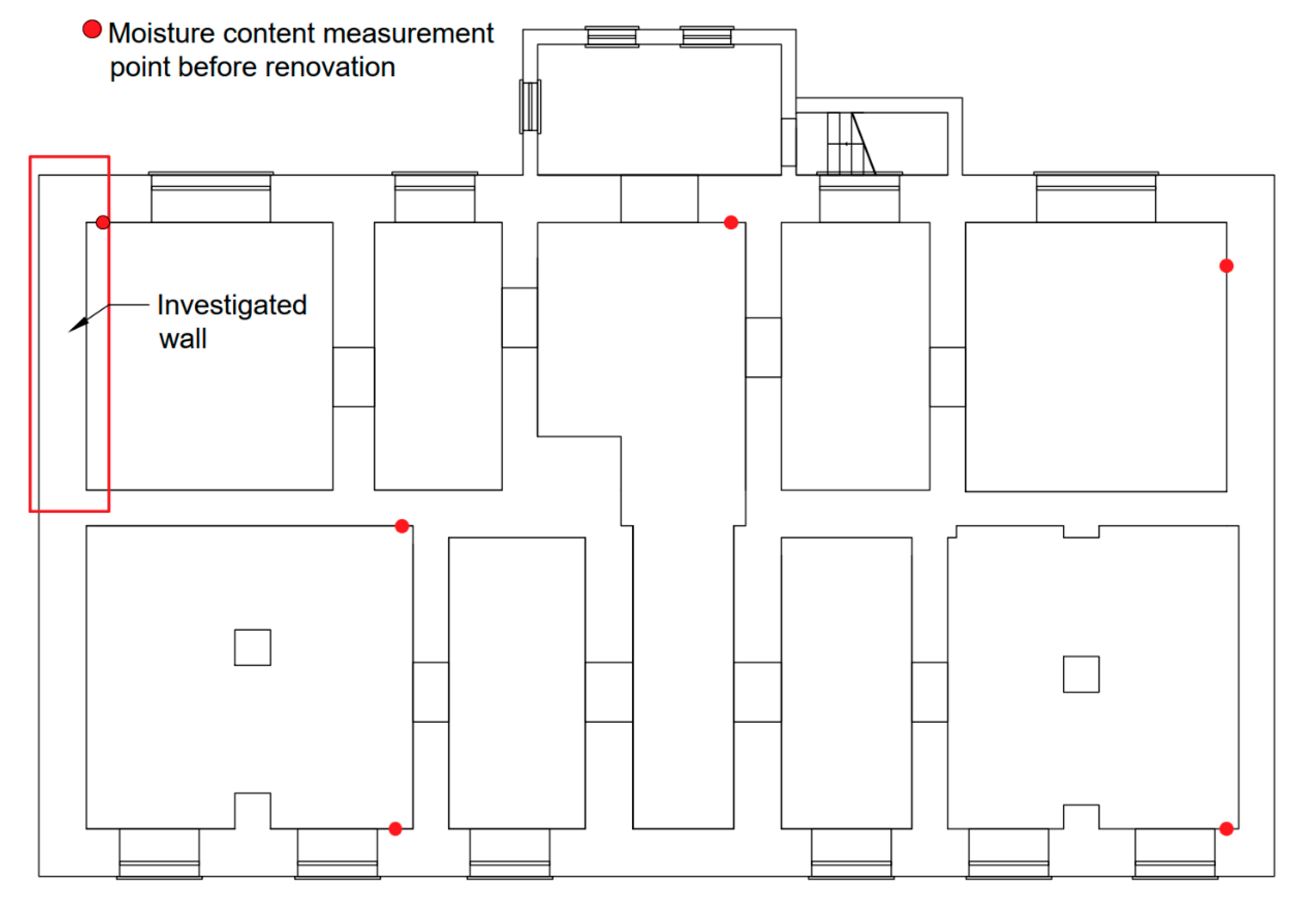
The building is made of red brick, has two floors with a high basement and is covered with a gable roof. The plan of the basement is shown in Figure 2. The masonry walls and the floor in the basement were also made of fired red bricks manufactured locally from local constituents. A lime-based joint was used. The thickness of the masonry walls in the basement varies from approximately 60 up to 80 cm. Moreover, the walls in the basement on the internal side are covered with lime-based plaster of the thickness approximately 2–3 cm (see Figure 3b with the wall structure). On the external side the walls are in the direct contact with the soil. Visual inspection of the building revealed the plaster degradation and salt crystallization sites, which were found both inside and outside the building. This means that the groundwater arose from the basement by capillary force action and evaporated at the internal and external side of the wall located above the ground. Nevertheless, before the renovation works, the moisture content in the masonry walls in the basement was measured by using the calcium carbide method (C-M Hydrometer by Gann). The measurements were carried out in six locations in the basement, which are presented in Figure 2. In each location, the holes were drilled approximately 10 cm above the basement floor, and the drilling residue from a depth of approximately 30–35 cm was analyzed. The measurements showed that the moisture content in the masonry walls was in the range of 5–11% wt. According to the building code, the level of moisture in the masonry walls was moderate to high. The recommended level is below 3% wt. The measurements show the necessity of drying masonry walls in the basement and ensuring horizontal and vertical waterproofing.
During the renovation, the building was subjected to several types of works. First of all, the masonry walls were dried and new waterproofing was ensured by using the thermo-injection method, which is described in the next subsection. Moreover, the old plaster was removed and the walls in the basement were covered with a special renovation plaster, which consists of three layers (i.e., Silten Renobase, Silten Renotop and Silten Renofine by Silten Terbud) of different properties. This lime-based plaster has a special composition and is characterized by hydrophobic properties, high porosity and high vapor permeability. Moreover, there are plans to remove the old floor and make a new one with thermal insulation from the ground.

2.2. Thermo-Injection Method for the Drying and Sealing of Masonry Walls

2.2.1. Method Description

The thermo-injection method [8,18,19,20] was used to carry out the renovation of the considered building. This method is classified as a convective method [8]. In this method, before the onset of drying, 20 mm holes are drilled in the wet wall in two staggered rows every 15 cm at a 30° angle from the horizon. The distribution of the drillings is presented in Figure 3a, while the cross-section of the upper drillings is presented in Figure 3b. The holes decrease the strength of the wall by approximately 5–10%. However, after drying and sealing, they are filled with special mortar (Silten Renoflow by Silten Terbud), injected into the holes using a membrane pump. This mortar has a special composition which prevents it from foaming and creating bubbles inside the holes. After this process, the strength of the wall is restored. Drying probes are placed in the upper drillings. These probes act as heaters and also supply fresh air close to the bottom of the hole. Air then flows out through the gap between the probe and hole to the surroundings. Next, through the probes and also by air, the wall is heated up and air that leaves the hole removes moisture from the wall. When the moisture content in the wall decreases bellow 3–4% wt. heating is stopped and a special hydrophobic silicone micro-emulsion SMK type (Silten Me by Silten Terbud) is immediately injected under elevated pressure to all holes. This process leads to the creation of the waterproof membrane, which prevents rewetting of the wall [18,19,20]. The silicone micro-emulsion in the aqueous solution has hydrophilic properties; therefore, it mixes well with water present in the building materials. After drying, it becomes hydrophobic. Moreover, the micro-emulsion does not react with the wall material. Based on the observation, it was found that the penetration depth is approximately 8–10 cm. Therefore, holes for injection are drilled in a staggered configuration with horizontal and vertical pitches as shown in Figure 3a and with the bottom approximately 5–10 cm from the external side of the wall as shown in Figure 3b. It should be noticed that the wall heating also improves the impregnation efficiency. The thermal energy accumulated in the hot wall increases the temperature of the micro-emulsion and reduces its viscosity during injection, which results in the deeper penetration into wall structure.
The thermo-injection method, even though it is an invasive method, is approved for use by historic preservation officers. It was successfully applied during the renovation of many historic and very precious buildings in Poland. The highland gate in Gdańsk, the Sejm building in Warsaw and Chopin’s birthplace in Żelazowa Wola are, among others, examples of the application of this method. This method has been used by the company Silten Terbud since the 1990s, and the waterproofing recreated in the first applications almost 20 year ago are still working well, effectively preventing damping in the walls. This proves that this method of waterproofing renovation is very durable.
The most important drawbacks of the thermo-injection method are the interference into the wall structure and the large consumption of energy for drying. However, the thermo-injection method is usually applied in the basement, where valuable plasters and ornaments are not present. Alternatively, the method may be applied on the external side; however, to do so, the foundations must be excavated, which increases the costs of works. The advantage of the method, compared to non-invasive methods, which are usually based on surface heating (e.g., convective, thermal radiative or microwave heating), is that it effectively dries and impregnates the wall through its whole thickness, and therefore, efficiently stops the capillary water rise. Moreover, in the case of microwave heating, there is the risk of a too high wall temperature increase or the occurrence of intensive water evaporation inside the wall. Chemically bonded water in building materials may also be removed. These effects might seriously deteriorate the wall structure. Microwaves are also dangerous for people. Such problems are not present in the thermo-injection method.

2.2.2. Drying Device Description

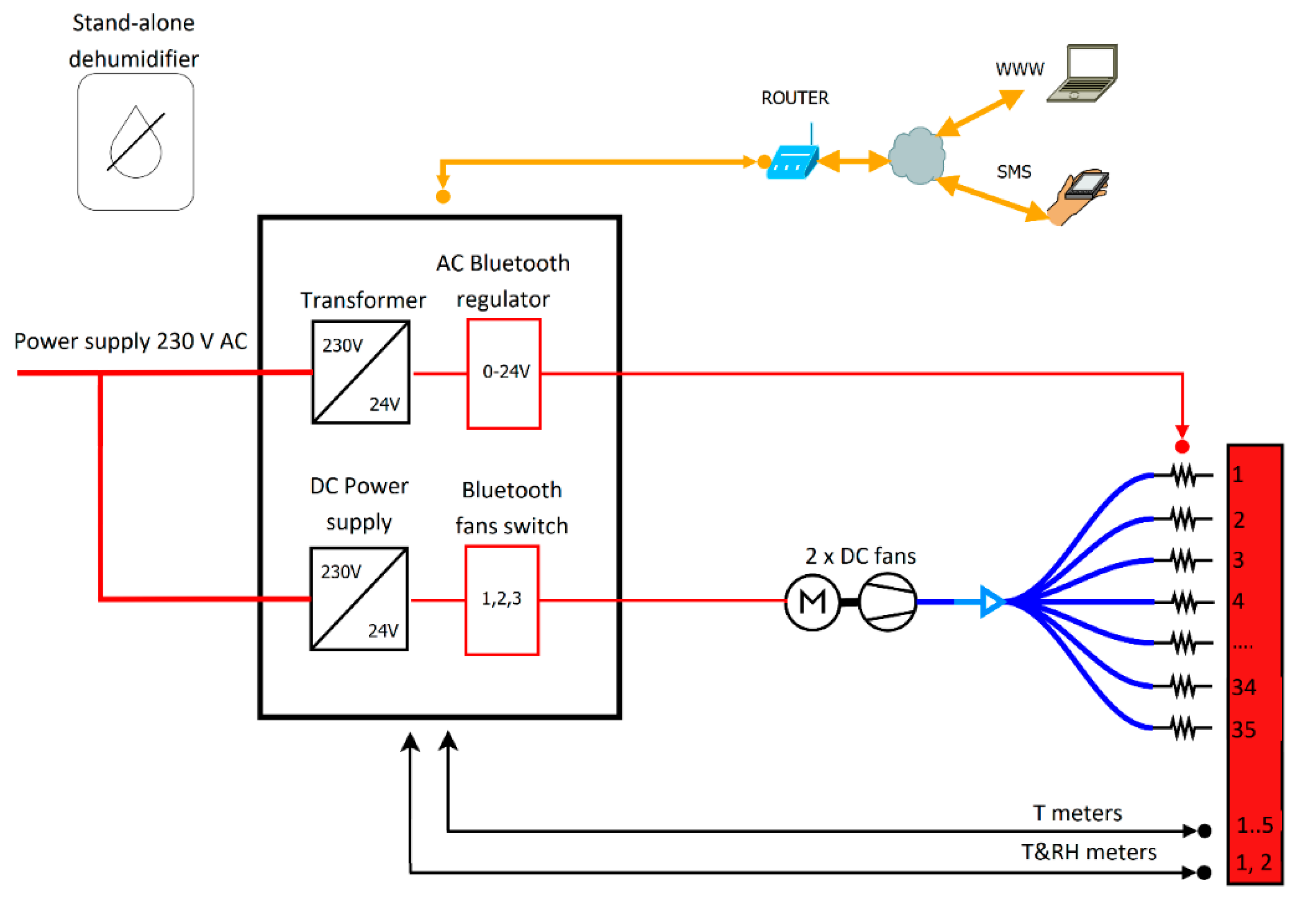
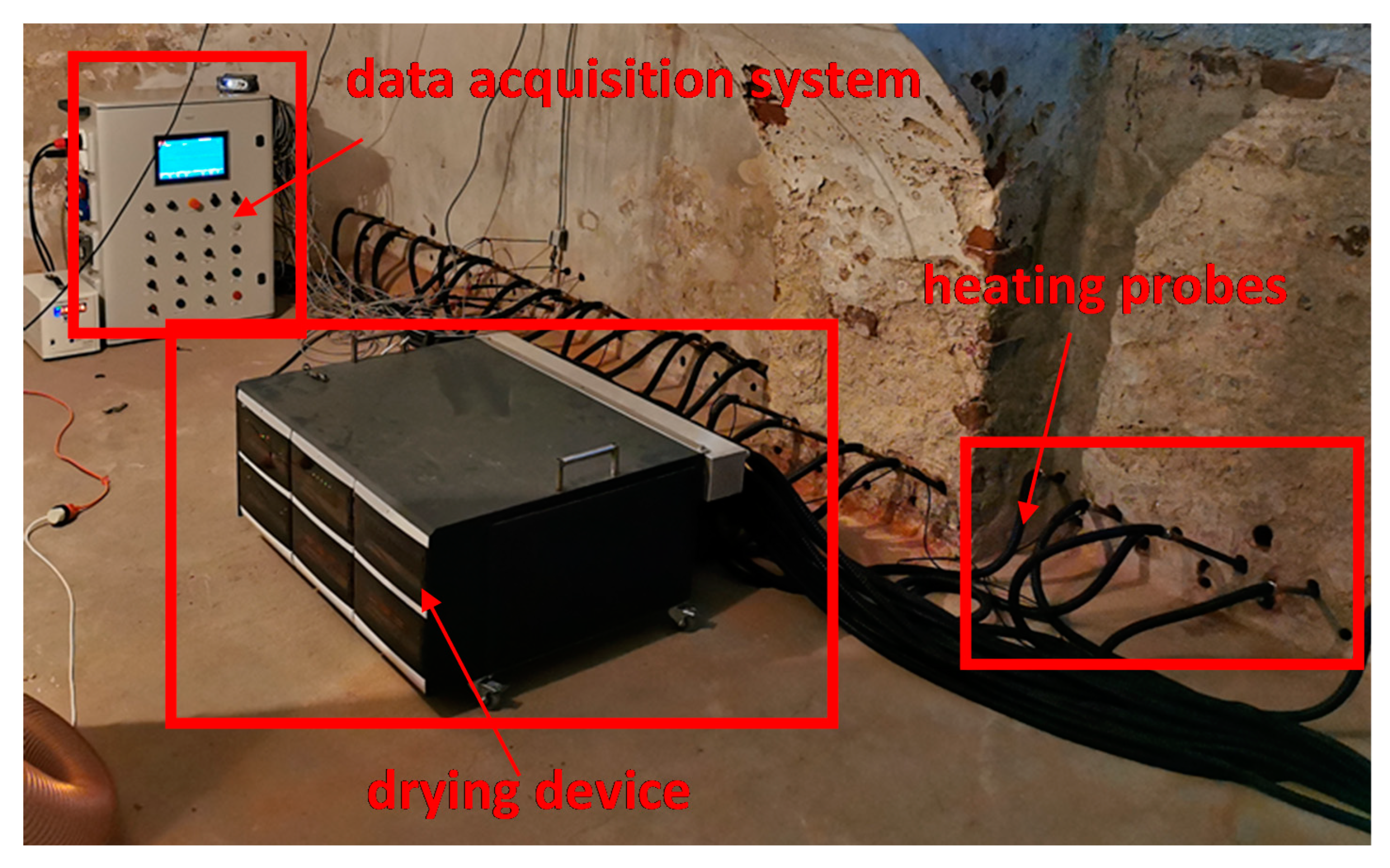
The prototype of the device used for drying of the wet wall was developed within the project DryWall (no. POIR.04.01.02-00-0099/16) founded by the National Centre for Research and Development (Poland). Simplified schematics of the device and a picture of the device and probes mounted to the wet wall as well as a picture of the data acquisition and control system are presented in Figure 4 and Figure 5, respectively. This device is designed to carry out the drying of 5 m of masonry wall at one time. In order to achieve this goal, the device is equipped with two DC 24 V fans providing air stream to 35 heating probes through a distribution collector and metal spiral hose with outer electric insulation. Fans are controlled using a Bluetooth switch that allows to set three fan speeds corresponding to the air velocities and flow rate at the exit from the probe, namely, 2.7, 3.1 and 3.8 m/s and 1.95, 2.25 and 2.75 m3/h, respectively. Heating probes are powered by 24 V AC and controlled by a Bluetooth proportional–integral–derivative (PID) regulator. Probes are made of brass tubes with a diameter and length of 16 mm and 50 cm, respectively. Brass tubes act as 40 watts electric heaters that generate heat, and as air ducts that lead air to the bottom of the drilled holes. For the automatic control and monitoring of the drying process, five resistive PT1000 temperature detectors (one per meter of wet wall) and two temperature and relative humidity sensors were installed in the wall (see Figure 3a). Heating probes were grouped in five sections containing seven probes. Each section is supplied by an individual transformer and may have different temperature control values. Each probe has a state signalization which allows for the detection of malfunction. Moreover, a standalone dehumidifier was used to reduce the humidity of air sucked up by the device.

2.3. Measurements Method

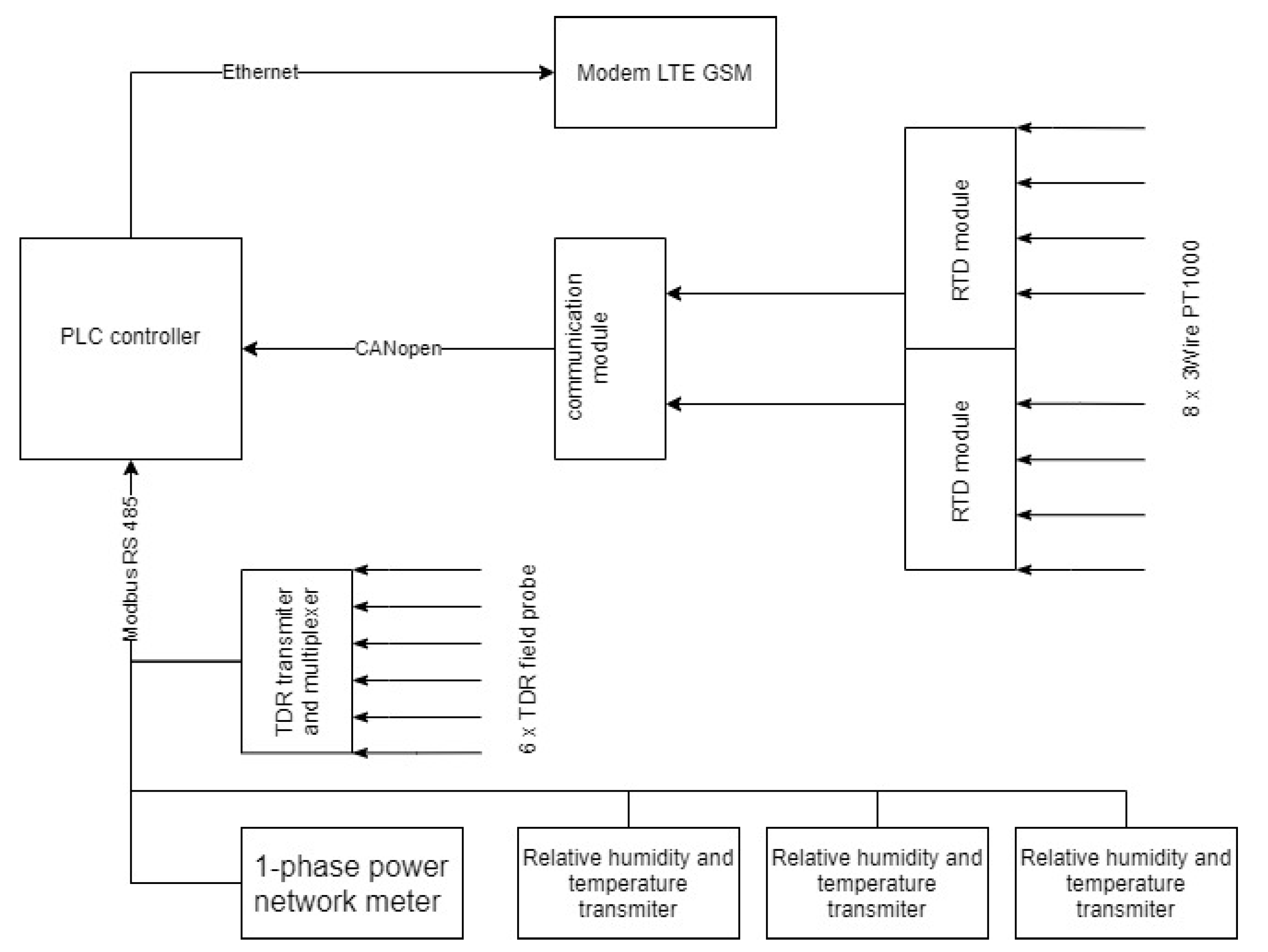
For investigating and monitoring the drying process, a dedicated data acquisition system was developed. The schematics of the system are presented in Figure 6. The main element of the system was the programmable logic controller (PLC) controller (XV 303 by Eaton Industries GmbH) equipped with a 10” screen. The PLC controller collected data from all sensors, saved them on the internal memory and allowed for remote contact via LTE GSM modem. The following sensors were used by the data acquisition system:
  • For air temperature and relative humidity measurements: three transducers (AR 252 by APAR) with an accuracy of ±0.3 °C for temperature and ±2% for relative humidity. The communication with the PLC controller was via the Modbus RS 485 protocol. Measurements were carried out in three locations, i.e., in the middle of dried room, approximately 0.5 m from the ceiling, close to the drying device inlet and close to the wet wall, approximately 10 cm from the floor.
  • For wall volumetric moisture content measurements: the time-domain reflectometry device (TDR/MUX/MPTS by E-TEST) with six field probes with a maximum error of ±2% for moisture content. The locations of the probes are presented in Figure 3a. The numbering of the probes starts from the right to left. Probes were made from two sharpened acid-resistant steel rods and PCV tube and were placed in slots of 20 mm diameter and 30 cm depth filled with drilling residue for easier installation. The communication with the PLC controller was via the Modbus RS 485 protocol.
  • For wall temperature measurements: six three-wire resistance temperature detectors were used with the A tolerance class, with the maximum acceptable error defined in standards lower than ±0.3 °C for the whole temperature range measured during investigation, connected through two analog input modules (XN-322-4AI-PTNI by Eaton Industries GmbH) and linked to the communication module (XN-312-GW-CAN by Eaton Industries GmbH). Stainless steel sheathed probes with a diameter of 4.5 mm were placed in 30 cm-deep slots in locations presented in Figure 3a. The numbering of the probes starts from the right to left. The communication with the PLC controller was via the CANopen protocol.
  • For electrical parameters measurements: the 1-phase power network meter (N27P by LUMEL) with 32/63 A measurement range was used. The meter allowed for the measurements of: current (basic error ±0.2%), voltage (basic error ±0.2%), frequency (basic error ±0.2%), active power (basic error ±0.5%), reactive power (basic error ±0.5%), apparent power (basic error ±0.5%), active energy (basic error ±0.5%) and reactive energy (basic error ±0.5%). Communication with the PLC controller was via the Modbus RS 485 protocol.
The whole system and sensors were checked for possible interaction. Test measurements were carried out for each sensor working separately and for all sensors working together. During these tests, the drying device was turned off and on. The only detected possible interference problem was between TDR probes. However, measurements applying these sensors were carried out in sequence, so the interferences were eliminated.

3. Results and Discussion

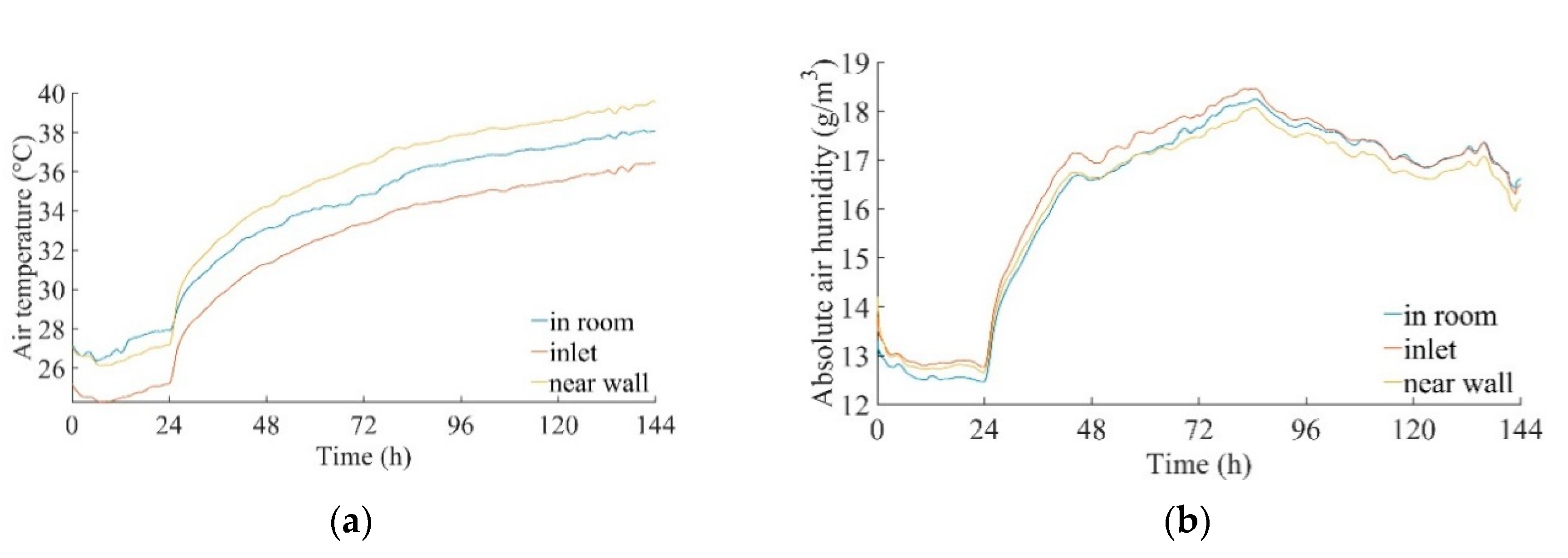
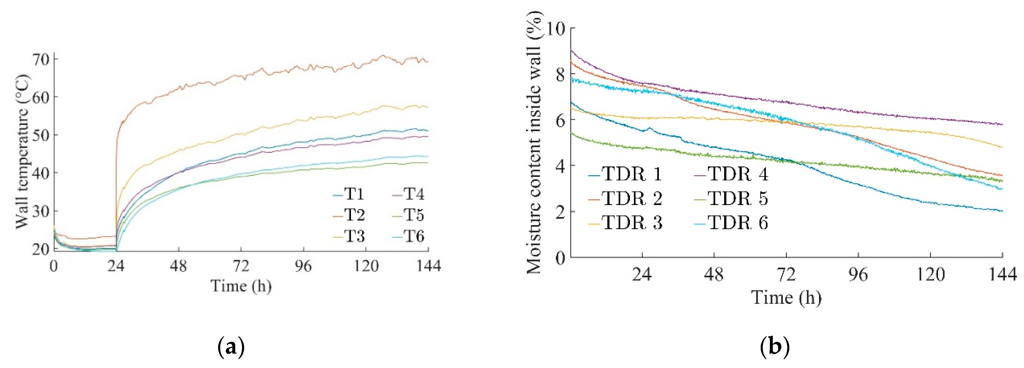
The drying process using the drying device and data acquisition and control system described above was carried out in the basement of the considered building. The renovation works were conducted in August 2020. In this paper, only the results of in situ monitoring of the process for one 5-m-long part of the external masonry wall are presented. The wall had a thickness of 80 cm and a structure shown in Figure 3b. For the other masonry walls, similar behavior was observed. The process begun without heating, with fans switched on and set at the second speed. This stage lasted 24 h and was characterized by quite stable air temperatures, presented in Figure 7a. The slight decrease of the absolute air humidity shown in Figure 7b was a combined effect of moisture gained from the wet wall and moisture captured by the dehumidifier. In the first stage of drying, moisture was removed mainly from the surface of the wall as well as surfaces of drillings and their surroundings. The temperature drop of the wall seen in Figure 8a in the first hours was connected to achieving the local saturation temperature of the wall.
The second period of drying started after 24 h when heating was turned on and the fan was operated without changes. This affected both the air and wall temperature, which started to increase—see Figure 7a and Figure 8a. Differences between temperature variations for different points shown in Figure 8a resulted from different distances from sensors to heating holes and differences in the wall structure—it was very difficult to precisely drill the holes for probes and sensors. The highest temperature observed for point T2 in Figure 8a was a result of an accidental connection during the drilling of slots for the drying probe and temperature sensor. This sensor showed a temperature that was very close to the temperature of the heating probe. As the process progressed, the wall temperature stabilized. Differences in the behavior of moisture content in the wall, presented in Figure 8b, were connected to the variation in the local content of the water in the wall as well as with the material which surrounded the slots. The TDRs 3–5 were in locations surrounded by a much higher amount of mortar than TDR 1, 2 and 6, which were in locations surrounded by ceramic brick. In the first stage of drying, the reduction of moisture content was rapid even without heating; after 24 h, additional heating was necessary to maintain the drying rate. Finally, after 144 h of drying, TDR probes 1–6 indicated a moisture content inside the wall of 2%, 3.6%, 4.8%, 5.9%, 3.4% and 3% vol., respectively.
Figure 9 presents the results of the infrared image of the surrounding of two heating slots for the end of the drying process. The surface temperature of the wall between the heating probes oscillated around approximately 43 °C, while the surface temperature close to the heating probes reached approximately 53 °C. The thermogram clearly shows the drying and heating area, which was a strip of approximately 12 cm width.
During the 6 days of the drying process, the drying device consumed 208.6 kWh of energy with a mean active power of 241 W and 1688 W for the drying stage without and with heaters, respectively. At the same time, a 3.77% vol. moisture content reduction was observed on average in the wall. The new parameter, i.e., the specific energy consumption, was introduced to express the relation between the energy consumption and the amount of moisture removed from the wall. The specific energy consumption during the drying process was defined as the energy consumption divided by the mean volumetric moisture content (MC) difference between the initial and final state in the wall and by the length of the dried wall section. For the considered wall, it was equal to 11.08 kWh/MC%/m. This value is considered as satisfactory. The reactive power consume by the device was capacitive, which was due to the installed DC power supplies. When heaters were turned on, the power factor was high, so the device did not need reactive power compensation. Detailed energy parameters measured during the drying process are shown in Table 1.
During the six days of the drying process, the moisture content of the wall decreased to a value allowing for effective infiltration of the wall by the hydrophobic silicone micro-emulsion, i.e., to a mean level of 3.76% vol. (2.35% wt.). The increased temperature of the wall not only facilitated moisture removal but also had a positive effect on the impregnation process, i.e., high wall temperature decreased the viscosity of the micro-emulsion, which encouraged its depth infiltration and generation of waterproof membrane.

4. Conclusions

In this paper, hygro-thermal behavior of the wet wall during its drying process was monitored in situ. The considered wall was part of the basement of a historical building which was renovated. The drying process was conducted by applying the thermo-injection method and the novel protype of the device to its implementation developed with the project DryWall. By applying the dedicated data acquisition system developed to in situ monitor parameters of the drying process, the following quantities were registered: the air temperature and relative humidity in various locations in the basement, temperatures and moisture contents in several points in the wet wall and electrical parameters of the drying device. The obtained results may be concluded as follows:
  • The drying process resulted in the increase of the drying zone temperature up to 40–55 °C depending on the distance from the heating probes. After six days of drying, the wall temperature attained stabilization.
  • The moisture was effectively removed from the wall. After six days of drying, the moisture content dropped to a mean level of 3.76% vol. (2.35% wt.), which is a value that allows effective impregnation of the wall with the hydrophobic silicone micro-emulsion. This fluid is used to create horizontal and vertical waterproofing in the wall. Moreover, the high temperature of the wall not only facilitated moisture removal, but also helped in the infiltration of the wall by the hydrophobic fluid.
  • The energy consumption during the process was equal to 208.6 kWh. This value included heating and working of fans. The new parameter, i.e., the specific energy consumption, was also defined to refer to the energy consumption to the amount of moisture removed from the wall. For the considered wall, it was equal to 11.08 kWh/MC%/m.

Author Contributions

Conceptualization, Ł.C. and P.Ł.; methodology, Ł.C., P.Ł. and R.M.; software, Ł.C. and R.M.; validation, Ł.C. and P.Ł.; formal analysis, Ł.C. and P.Ł.; data curation, Ł.C. and R.M.; investigation, Ł.C. and R.M.; writing—original draft preparation, Ł.C. and P.Ł.; writing—review and editing, P.Ł.; visualization, Ł.C. and R.M.; supervision, P.Ł.; project administration, P.Ł.; funding acquisition, P.Ł. All authors have read and agreed to the published version of the manuscript.

Funding

This work was supported by the European Union within the European Regional Development Fund under project no. POIR.04.01.02-00-0099/16 “Development of innovative technology of drying and moisture sealing of masonry walls, DryWall” granted by the National Centre for Research and Development (Poland).

Conflicts of Interest

The authors declare no conflict of interest.

References

  1. De Santoli, L.; Mancini, F.; Rossetti, S.; Nastasi, B. Energy and system renovation plan for Galleria Borghese, Rome. Energy Build. 2016, 129, 549–562. [Google Scholar] [CrossRef]
  2. Phillipson, M.C.; Baker, P.H.; Davies, M.; Ye, Z.; McNaughtan, A.; Galbraith, G.H.; McLean, R.C. Moisture measurement in building materials: An overview of current methods and new approaches. Build. Serv. Eng. Res. Technol. 2007, 28, 303–316. [Google Scholar] [CrossRef]
  3. Válek, J.; Kruschwitz, S.; Wöstmann, J.; Kind, T.; Valach, J.; Köpp, C.; Lesák, J. Nondestructive Investigation of Wet Building Material: Multimethodical Approach. J. Perform. Constr. Facil. 2010, 24, 462–472. [Google Scholar] [CrossRef]
  4. Fidríková, D.; Greif, V.; Dieška, P.; Štofanik, V.; Kubičár, L.; Vlčko, J. Monitoring of the temperature-moisture regime in St. Martin’s Cathedral tower in Bratislava. Environ. Earth Sci. 2013, 69, 1481–1489. [Google Scholar] [CrossRef]
  5. Zegowitz, A.; Renzl, A.; Hofbauer, W.; Meyer, J.; Kuenzel, H. Drying behaviour and microbial load after water damage. Struct. Surv. 2016, 34, 24–42. [Google Scholar] [CrossRef]
  6. Walker, R.; Pavía, S. Thermal and moisture monitoring of an internally insulated historic brick wall. Build. Environ. 2018, 133, 178–186. [Google Scholar] [CrossRef]
  7. Rymarczyk, T.; Sikora, J.; Tchórzewski, P. Implementation of electrical impedance tomography for analysis of building moisture conditions. COMPEL Int. J. Comput. Math. Electr. Electron. Eng. 2018, 37, 1837–1861. [Google Scholar] [CrossRef]
  8. Cieślikiewicz, Ł.; Łapka, P.; Mirowski, R.; Wasik, M.; Kubiś, M.; Pietrak, K.; Furmański, P.; Seredyński, M.; Wiśniewski, T. Development of the experimental stand for investigation of the drying process in moist walls. IOP Conf. Ser. Mater. Sci. Eng. 2019, 660, 012021. [Google Scholar] [CrossRef]
  9. Hoła, A.; Sadowski, Ł. A method of the neural identification of the moisture content in brick walls of historic buildings on the basis of non-destructive tests. Autom. Constr. 2019, 106, 102850. [Google Scholar] [CrossRef]
  10. Hoła, A.; Sadowski, Ł. Verification of a nondestructive method for assessing the humidity of saline brick walls in historical buildings. Appl. Sci. 2020, 10, 6926. [Google Scholar] [CrossRef]
  11. Orr, S.A.; Fusade, L.; Young, M.; Stelfox, D.; Leslie, A.; Curran, J.; Viles, H. Moisture monitoring of stone masonry: A comparison of microwave and radar on a granite wall and a sandstone tower. J. Cult. Herit. 2020, 41, 61–73. [Google Scholar] [CrossRef]
  12. Hoła, A. Methodology for the in situ testing of the moisture content of brick walls: An example of application. Arch. Civ. Mech. Eng. 2020, 20, 1–13. [Google Scholar] [CrossRef]
  13. Cabrera, V.; López-Vizcaíno, R.; Yustres, Á.; Ruiz, M.Á.; Torrero, E.; Navarro, V. A functional structure for state functions of moisture transfer in heritage building elements. J. Build. Eng. 2020, 29. [Google Scholar] [CrossRef]
  14. Van Belleghem, M.; Steeman, M.; Janssen, H.; Janssens, A.; De Paepe, M. Validation of a coupled heat, vapour and liquid moisture transport model for porous materials implemented in CFD. Build. Environ. 2014, 81, 340–353. [Google Scholar] [CrossRef] [Green Version]
  15. Seredyński, M.; Wasik, M.; Łapka, P.; Furmański, P.; Cieślikiewicz, Ł.; Pietrak, K.; Kubiś, M.; Wiśniewski, T.S.; Jaworski, M. Analysis of Non-Equilibrium and Equilibrium Models of Heat and Moisture Transfer in a Wet Porous Building Material. Energies 2020, 13, 214. [Google Scholar] [CrossRef] [Green Version]
  16. Berardi, U.; Tronchin, L.; Manfren, M.; Nastasi, B. On the effects of variation of thermal conductivity in buildings in the Italian construction sector. Energies 2018, 11, 872. [Google Scholar] [CrossRef] [Green Version]
  17. Kubiś, M.; Pietrak, K.; Cieślikiewicz, Ł.; Furmański, P.; Wasik, M.; Seredyński, M.; Wiśniewski, T.S.; Łapka, P. On the anisotropy of thermal conductivity in ceramic bricks. J. Build. Eng. 2020, 31. [Google Scholar] [CrossRef]
  18. Matuszewska, M.; Matuszewski, T. Method of Uniformly Heating Holes in a Masonry Wall during Drying Same and Protecting It against Absorption of Moisture as well as Heating Element Therefor. Polish Patent 184012, 3 October 1997. [Google Scholar]
  19. Matuszewski, T. Method for Drying and Protecting the Walls against Repeated Rising Damp. Polish Patent 219284, 30 September 2009. [Google Scholar]
  20. Matuszewski, T.; Olędzki, M. Method for Drying Walls and Protect Them from Moisture Afresh. Polish Patent 223771, 31 October 2012. [Google Scholar]
Figure 1. The renovated building.
Energies 13 06190 g001
Figure 2. Plan of the renovated basement with locations of the initial moisture content measurement points.
Energies 13 06190 g002
Figure 3. Schemas with locations of drilling holes and monitoring sensors: (a) Positions of the drilling holes and sensors in the wet masonry wall and (b) the cross-section of the masonry wall along the upper drilling hole with the wall structure (dimensions in mm).
Energies 13 06190 g003
Figure 4. Schematics of the drying device.
Energies 13 06190 g004
Figure 5. The drying device with probes mounted to a wet wall, as well as the data acquisition and control system, in the basement of the considered building in Łowicz.
Energies 13 06190 g005
Figure 6. Schematics of the data acquisition system.
Energies 13 06190 g006
Figure 7. Air parameters during the drying process. (a) Temperature, (b) absolute humidity.
Energies 13 06190 g007
Figure 8. Wet wall parameters. (a) Temperature and (b) volumetric moisture content.
Energies 13 06190 g008
Figure 9. Thermogram of two drying probes and their surrounding at end of drying process.
Energies 13 06190 g009
Table 1. Energy parameters during the drying process.
ParameterUnitValue
Specific energy consumptionkWh/MC%/m11.08
Mean moisture content reduction% vol. (% wt.)3.77 (2.35)
Energy consumptionkWh208.6
Mean active power without heatersW241
Mean apparent power without heatersVA405
Mean reactive power without heatersVAr−325
Mean power factor without heaters-0.595
Mean active power with heatersW1 688
Mean apparent power with heatersVA1 725
Mean reactive power with heatersVAr−356
Mean power factor with heaters-0.978
Publisher’s Note: MDPI stays neutral with regard to jurisdictional claims in published maps and institutional affiliations.