Article

Thermal Performance Analysis of the Charging/Discharging Process of a Shell and Horizontally Oriented Multi-Tube Latent Heat Storage System

Thermal Energy Storage Group, CREST, Loughborough University, Loughborough LE11 3TU, UK
*
Author to whom correspondence should be addressed.
Energies 2020, 13(23), 6193; https://doi.org/10.3390/en13236193
Submission received: 30 October 2020 / Revised: 17 November 2020 / Accepted: 23 November 2020 / Published: 25 November 2020
(This article belongs to the Section D: Energy Storage and Application)

Abstract

:
In this study, the thermal performance of latent heat thermal energy storage system (LHTESS) prototype to be used in a range of thermal systems (e.g., solar water heating systems, space heating/domestic hot water applications) is designed, fabricated, and experimentally investigated. The thermal store comprised a novel horizontally oriented multitube heat exchanger in a rectangular tank (forming the shell) filled with 37.8 kg of phase change material (PCM) RT62HC with water as the working fluid. The assessment of thermal performance during charging (melting) and discharging (solidification) was conducted under controlled several operational conditions comprising the heat transfer fluid (HTF) volume flow rates and inlet temperatures. The experimental investigations reported are focused on evaluating the transient PCM average temperature distribution at different heights within the storage unit, charging/discharging time, instantaneous transient charging/discharging power, and the total cumulative thermal energy stored/released. From the experimental results, it is noticed that both melting/solidification time significantly decreased with increase HTF volume flow rate and that changing the HTF inlet temperature shows large impacts on charging time compared to changing the HTF volume flow rate. During the discharging process, the maximum power output was initially 4.48 kW for HTF volume flow rate of 1.7 L/min, decreasing to 1.0 kW after 52.3 min with 2.67 kWh of heat delivered. Based on application heat demand characteristics, required power levels and heat demand can be fulfilled by employing several stores in parallel or series.

1. Introduction

Thermal energy storage (TES) may have a key part to play in supporting the achievement of the UK’s net emissions of greenhouse gases target and reduce the CO2 emissions in the UK domestic heating sector [1]. TES systems can enable collected low-grade heat (such as low-temperature industrial waste heat), to be used to meet both space heating and hot water demands in buildings. It can also help to reduce additional future strains on the UK electricity grid that could result from electricity demands resulting from increased use of heat pumps and other electricity-based heating technologies.
TES can provide a low-cost way to help increase the use of intermittent electrical production from renewable energy systems and heat from solar thermal technologies (that only generate heat during daytime, or only in summer) by enabling heat loads that are not concurrent with generation to be met. Thermal energy storage (i) enables intermittent energy supplies to be used to meet heat demands, (ii) can improve system efficiency, and (iii) expand opportunities for low carbon heating [2].
Depending on the material utilized as the storage medium, TES can be broadly divided into two groups, thermophysical and thermochemical, the former based on the temperature difference and/or latent heat due to phase change, and the latter on the reaction or sorption enthalpy [3,4].
For solar heating systems, adding phase change material (PCM) can significantly increase the thermal energy storage capacity [5]. Using PCMs can reduce the volume of the storage tank required compared to a conventional sensible heat storage system.
Despite the potential benefits for certain applications that PCMs can provide, many systems still use sensible heat storage and are yet to develop and utilize PCMs with an embedded HX (heat exchanger) for thermal energy storage. A carefully designed system is necessary to ensure heat transfer to and from the storage accounting for time restrictions imposed by both availability and demand for heat [6]. The HX should be designed such that it allows high energy storage density and rapid charging and discharging by providing high heat transfer rates for low-temperature differences to ameliorate the low thermal conductivity of most PCMs [7,8] while providing a cost-effective thermal storage system.
To date, a large number of studies have investigated different design configurations of PCM thermal energy storage systems to understand and evaluate the temperature distributions and heat transfer that takes place between the solid and liquid PCM at the phase transition front. These help to provide the required knowledge to determine the optimum store design which can achieve the highest effectiveness for each application. However, the design and optimization of a LHTESS for different applications is still incomplete and additional research is required.
PCM based HX systems come in many shapes and forms with different mechanisms used to enhance heat transfer, a selection of these are illustrated in Agyenim et al. [9] Systems similar to shell and tube HX have attracted much attention and can be classified into two main groups, shell and tube HXs consisting of a single tube or multiple tubes inside a store (shell) and the triple concentric tube HX [10].
Previous studies have focused mainly on operating and design parameters including HTF mass flow rate, HTF inlet temperature, the direction of HTF flow, the orientation of HX, number of tubes and arrangement in shell and tube HX, and the diameters of shell and tubes to optimize the charging and discharging processes.
A. Egea and J. García [11] experimentally tested the thermal performance of a solar-driven shell and tube thermal store using RT70HC as the PCM. The results show that natural convection plays a significant role in the charging process.
S. Pakalka et al. [12] experimentally assess and compare the operations of two PCM-based fin and tube copper HX to overcomes the low thermal conductivity of the PCM which causes long melting and solidification times.
M. Osman et al. [13] experimentally studied the capability of a multitube HX filled with a paraffin wax (Alex PW600) to serve as a heat storage store in solar domestic hot water heating systems. They recommend that according to the application and the available HTF inlet temperature, the HTF volume flow rate should be adjusted to meet the design requirements such as duration of discharge and to ensure that a useable HTF outlet temperature was achieved.
The effect of the eccentricity of the tube in HX design on melting and discharging characteristics of a paraffin PCM in a horizontal shell and tube type storage unit for different HTF inlet temperature is experimentally investigated by M.Y. Yazıcı et al. [14,15]. The experimental results show that the natural convection dominated area enlarged and that the melting rated increased substantially when the inner tube was moved downward from the center of the outer shell. However, the total solidification process is increasing with the increase of the eccentricity of the HTF tune either downward or upward from the center of the outer shell.
V. Saydam et al. [16] experimentally analyzed the thermal performance of a helical coil PCM-HX for TES using a Paraffin wax as heat storage material. The experimental results showed that the inlet temperature of the HTF has a greater influence on the melting time than the HTF volume flow rate. The charging time was shortened by 35% when the HTF inlet temperature was increased from 70 °C while increasing the HTF flow rate from 0.5 to 4.0 L/min reduced the charging time by up to 21%. However, the discharging time did not change considerably with HTF flow rates.
A numerical simulation carried out by S Riahi et al. [8] showed that adopting a periodic reversal of flow enhanced heat transfer performance in a shell and tube LHTESS, leading to a reduction in melting and solidification times by 10% and 12%, respectively.
The effect of geometric configuration on the thermal behavior of a vertical shell-and-tube LHTESS has been evaluated by S. Seddegh et al. [17]. Two cylindrical and conical systems were compared experimentally to illustrate the effects of natural convection on heat transfer in the PCM during melting and solidification. The results showed that due to natural convection, the liquid PCM accumulated at the upper part of the store. The conical design could effectively utilize natural convection by having a larger volume of PCM in the upper zone where convection dominates during melting. However, during the discharging process, the conical and vertical sided designs showed little difference in terms of the total discharging time and energy discharge at the given time for a range of operating conditions.
Z.N. Meng and P. Zhang [18] experimentally and numerically investigated the heat transfer performance and characteristics of a tube-in-tank LHTESS containing a composite PCM composed of paraffin and copper foam using different HTF inlet temperatures and flow velocities during the heat charging and discharging processes. The results show that increasing the HTF inlet flow velocities and increasing the temperature difference between the PCM and HTF increased the heat transfer rate and shortened the time required for charging and discharging.
M. Avci and M. Y. Yazici [19] experimentally investigated the melting and solidification characteristics of paraffin wax (P56-58) in a horizontal shell-in-tube LHTESS. The results showed that the molten PCM rises to the upper part of the thermal store as a result of natural convection in the liquid PCM, then extends radially leading to a radially asymmetric temperature field. During the discharging process, natural convection was observed initially to increase heat transfer, however, when the PCM started to solidify on the heat transfer surfaces the heat transfer rate decreased with conduction in the solid PCM layer providing the dominant contribution.
Recent numerical and experimental studies have reported a significant enhancement in horizontal shell-and-tube LHTESS performance. S. Seddegh et al. [20] numerically investigated the heat transfer characteristics in horizontal and vertical shell-and-tube LHTESS. The predictions made indicated that a horizontal energy storage system has better heat transfer performance than a vertical thermal energy storage system, in particular during part-load thermal energy charging. During the discharging process, the heat transfer performance does not exhibit any significant difference between the horizontal and vertical energy storage units as heat transfer by conduction dominates in both orientations.
Finally, the effect of inclination angle on the thermal performance of a shell-and-tube LHTESS was experimentally investigated by N. Kousha and L. Kalapala [21,22].The experiments showed that thermal storage systems orientation has a major influence on the melting phenomenon and the rate of melting is faster in the horizontally oriented system compared to that for other inclinations. However, solidification is unaffected by the orientation of the LHTESS.
From the literature, it is evident that there is a requirement for simple low-cost latent heat storage units for integration with a selection of thermal systems to increase system performance. The store design could be optimized for use with a solar thermal system with heat collected by solar panels, used to directly charge a PCM filled latent heat storage system, which would be discharged at a later time to meet heat loads. Another potential application is in conjunction with an air source heat pump, allowing the heat pump to be operated using low-cost off-peak electricity, charging the store which can subsequently be discharged at times of peak heat demand [23,24].
There are few studies that have evaluated the charging/discharging process in a horizontally oriented shell and multitube latent heat storage system. In this work, a series of experiments were conducted to study the effect of the HTF volume flow rate and inlet temperature on the melting/solidification of vegetable fatty acids (RT62HC) PCM and the density of thermal energy stored. The heat transfer in the thermal storage unit is assessed by measuring the PCM transient temporal temperature distributions throughout the store in vertical and horizontal planes and is valuable in developing and optimizing the future design of LHTESS.

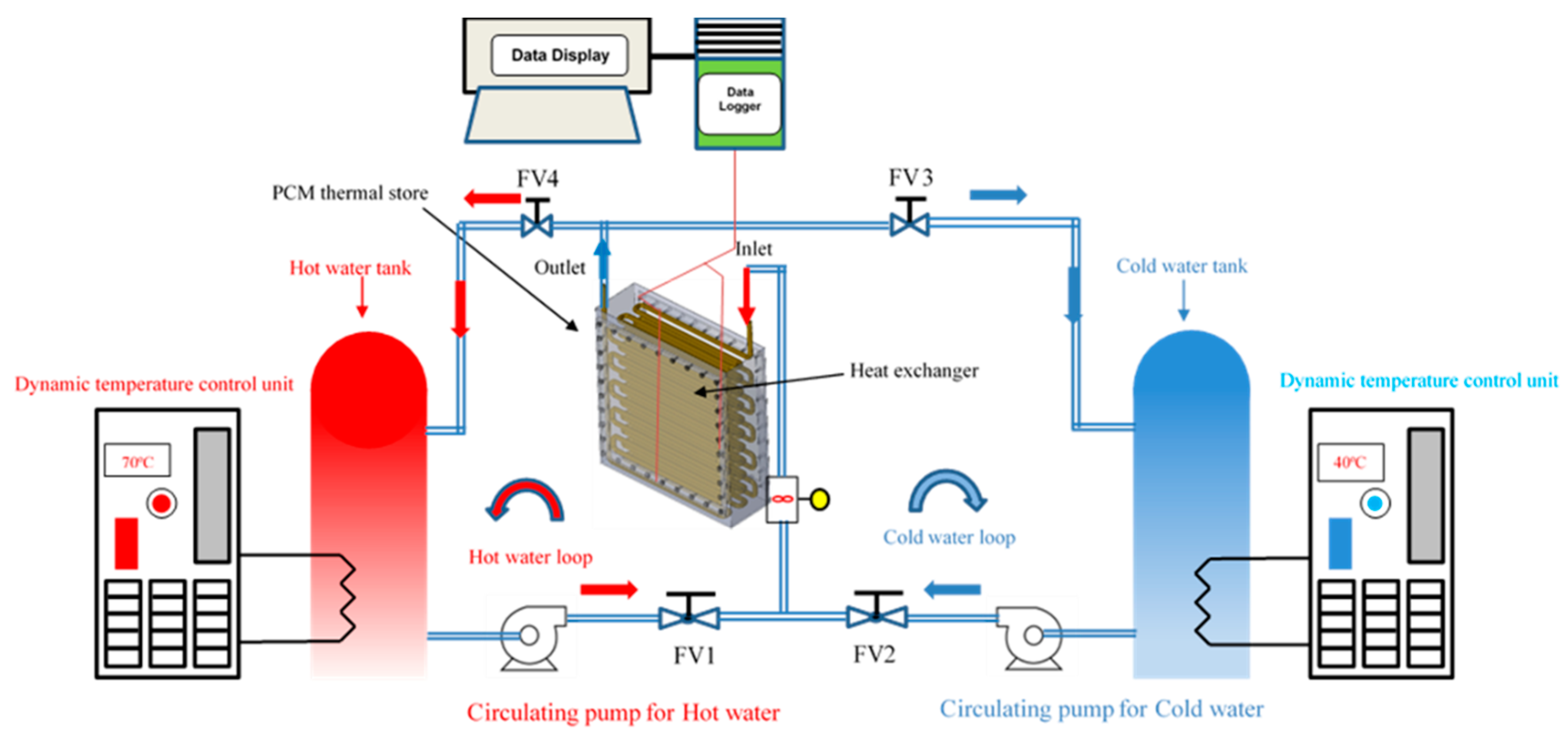
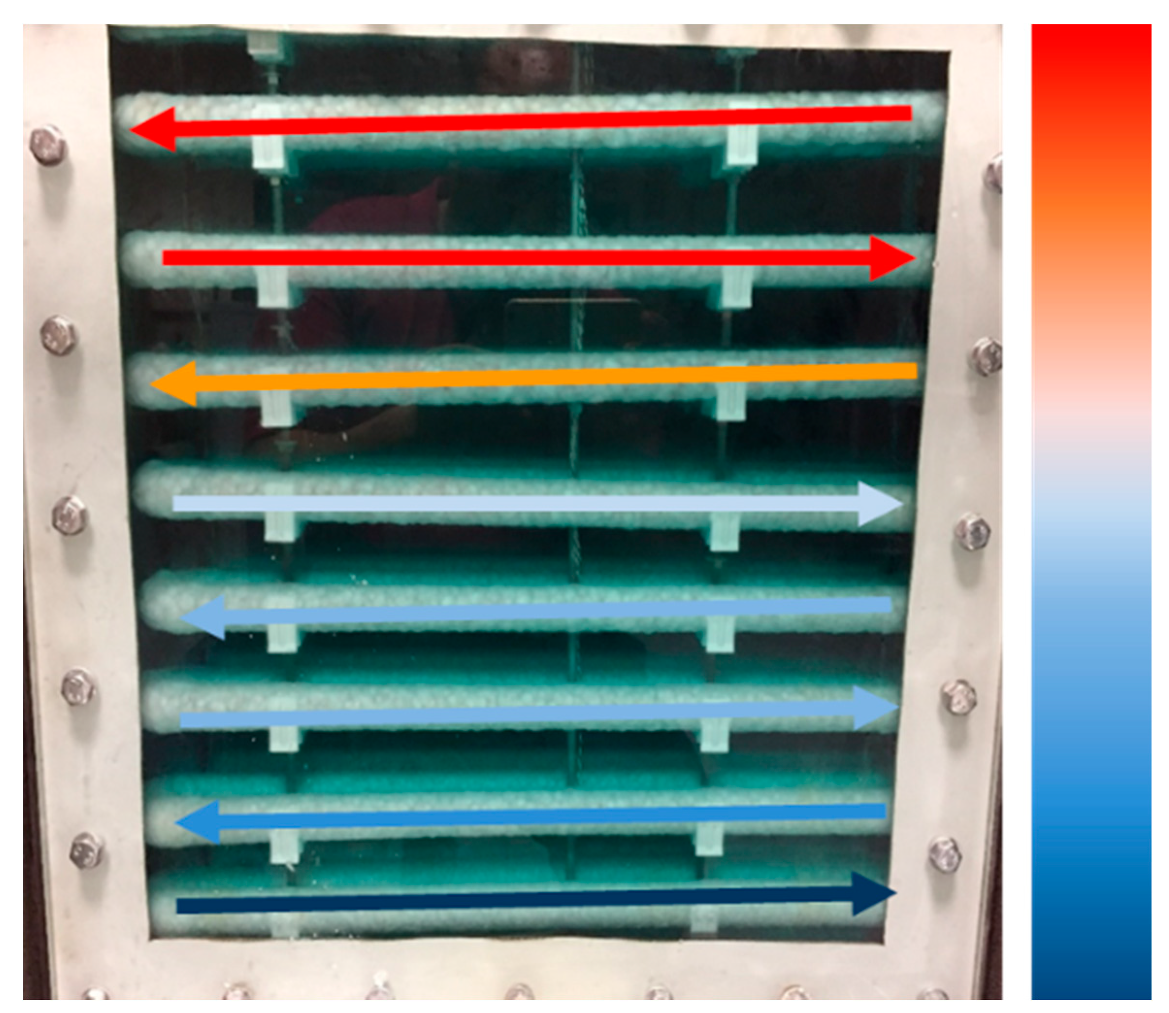
2. Experimental Setup

The experimental test program presented in this paper was performed at the Low-Temperature Lab-Scale Thermal Energy Storage Test Facility at Loughborough University [24,25]. A schematic diagram of the experimental system is presented in Figure 1.
The PCM storage unit was cuboid in shape with the external shell fabricated from 3 mm stainless steel sheet and has overall dimensions of 520 (length) × 560 (height) × 160 mm (width) providing a total volume of 46.5 L. The storage unit was fitted with a transparent glass observation window to observe the phase change process. The stainless-steel tank was surrounded with thermal insulation to prevent heat losses to ambient. The HX used in the present study was a horizontally oriented multipass copper tube HX with a total length of 27 m, fabricated from 15 mm OD, 1 mm wall thickness copper tube submerged in the PCM in the storage tank. The HX had 11 passes with nine turns on each pass, the HX inlet and outlet were both located at the top of the thermal store. FOAMGLAS® READY Board [26] of thickness 100 mm and thermal conductivity of 0.041 W/m K was used to provide thermal insulation on all exterior surfaces of the store.
A total number of 24 T-type thermocouple sensors (T1T24) (accuracy ± 0.5 °C) were mounted in the PCM storage unit as shown in Figure 2. The thermocouples were located on a 3D grid pattern at four vertical levels (referred to as lower position (1), central lower position (2), central upper position (3), and upper position (4)). The vertical spacing between each thermocouple in six zones (referred to as A, B, C, D, E, and F) was 100 mm as shown in Figure 2. The spatial distribution of the horizontal and vertical locations for the thermocouple probes were selected to provide a three-dimensional temperature distribution in the PCM store. Two Pt1000 sensors (with an error of ±0.2 °C) were located at the inlet and the outlet of the HX to measure the HTF temperature during the charging/discharging experiments.
Thermocouple sensor T25 was located at the base of the storage unit, near to the edge of the store and used to determine when the store was fully charged. Thermocouple sensor T26 was used to record the ambient laboratory temperature. The HTF volume flow rate was measured using a turbine pulse flow rate sensor (Gems™ FT-110 Series, Hall effect) [27].
The HTF volume flow rate and PCM temperature measurements were recorded using a data logger (Datataker DT85 [28]) and subsequently transferred to a computer for analysis. HTF temperatures and volume flow rate were registered during the charging/discharging process at five-second intervals.

2.1. Experimental Procedure

Before commencing the charging process, an initial conditioning process was required to obtain a uniform homogeneous temperature throughout the storage unit, at the desired initial conditions for the experiment (Tintial = 40 ± 1.0 °C). During this process, the HTF was circulated through the HX with the temperature maintained at the required set point temperature by the dynamic temperature control unit. Once the storage unit achieved the desired initial conditions, the valves were used to transfer the flow through the HX in the store, to water from the hot water storage tank for the charging process, with the desired water volume flow rate (measured by the flow meter) set using the valve FV-1 indicated in Figure 1.
The selected HTF inlet temperatures for charging experiments were 70, 75, and 80 °C to provide temperature differences of approximately 8, 13, and 18 °C between the inlet temperature of the HTF and the average melting temperature of the PCM. These values are representative of output temperatures from high-temperature air source heat pumps (HT-ASHP) that can be coupled with thermal energy storage [29] and solar water heating systems [30].
The HTF volume flow rate range (2.0–6.0 L/min) was selected to correspond to the range suggested for the Kingspan Thermomax HP evacuated tube solar collector (120 L/h to 480 L/h) [29].
The charging process was considered to be finished when thermocouple T25 measured temperatures above the PCM melt temperature (T25 = 70 °C), which indicated that all PCM in the store had melted. Once this temperature was reached, the discharging process commenced after setting the required flow rate and the desired discharge temperature. Valves FV-1 and FV-4 indicated in Figure 1 were closed, and valves FV-2 and FV-3 opened and set to maintain the required volume flow rate of cold water from the cold-water tank to the store. Data acquisition continued until the PCM temperature and outlet water temperature were the same, indicating discharging was complete.

2.2. Thermal Properties of RT62HC

In this study, the selection of the PCM was based on the temperatures available from the heat sources (solar thermal collector, high-temperature air source heat pumps) likely to be employed for space heating and domestic hot water applications. The required PCM melting temperature was determined to be in the range between 60 and 90 °C [31]. Based on this phase change temperature, the PCM container was filled with 37.8 kg of vegetable fatty acids RT62HC. This is a commercially available material (Rubitherm GmbH-Germany [32]). The thermophysical properties of RT62HC were obtained from the manufacturer’s datasheet [32] and are listed in Table 1.

2.3. Data Reduction

The time-varying thermal power input/output to/from the PCM, and the total heat input/release are calculated using Equations (1) and (2) [6,24].
Q ˙ i n p u t / o u t p u t = m ˙ H T F   C p ,   H T F   ( T i n ,   H T F T o u t ,   H T F )
Q c u m u l a t i v e = i = 0 i = n Δ t   m ˙ H T F     C p ,   H T F   ( T i n ,   H T F T o u t , H T F )
where m ˙ , C p ,   H T F   , T i n , H T F , and T o u t ,   H T F are the HTF mass flow rate, the temperature-dependent specific heat capacity of HTF evaluated at the average temperature of the inlet and outlet temperatures of the HTF, respectively.
The theoretical thermal energy stored in the store was evaluated accounting for both sensible and latent heat and calculated using Equation (3):
Q s t o r e d = m p c m   [ C p ,   p c m , s ( T m T i ) + Δ h m + C p , p c m ,   l ( T f T m ) ]
The average temperature of the PCM inside the full TES prototype was calculated at each measurement time using Equation (4):
P C M A v e _ t e m p = n = 1 n = 24 T n n
The Reynolds number (ReD) for the HTF flow was calculated using Equation (5).
R e D = 4 m ˙ π μ d   i n
where din is the HTF tube inner diameter and µ is the HTF dynamic viscosity.
Table 2 presents the calculated Reynolds numbers for the 12 charging/discharging experiments. Flow through a circular tube can be considered turbulent at Reynolds numbers larger than 2300, the flow regime is therefore expected to be turbulent for all experiments.
The ratio of sensible heat to latent heat, the Stefan number (Ste) [21,33] is defined by Equation (6).
S t e = C p   Δ T _   S t e Δ h m
where Cp and ΔT_Ste and ∆hm represent the sensible heat and latent heat content of the PCM, respectively. With ΔT_Ste = Tin, HTF − Tm for the charging process, and ΔT_Ste = TmTin, HTF for the discharging process. Table 3 presents Stefan number for each experimental test during charging/discharging process.
The storage efficiency of the LHTESS was calculated using Equations (7) and (8) from the total heat input to the store (during the charging process) or recovered from the store (during the discharging process) and the theoretical heat storage capacity.
η c h a r g i n g = H e a t s t o r e d H e a t i n p u t
η d i s c h a r g i n g = H e a t o u t p u t H e a t s t o r e d
where the theoretical heat storage capacity of the store was evaluated including both sensible and latent heat stored in the PCM.

2.4. Uncertainty Analysis

The overall percentage uncertainty of the calculated input/output power to/from the PCM can then be determined using Equation (9) [34].
Q ˙ i n p u t / o u t p u t Q ˙ i n p u t / o u t p u t ( m ˙ m ˙ ) 2 + ( T T ) 2
By considering the minimum/maximum HTF volume flow rate to be 1.7 and 6.0 L/min and minimum/maximum HTF inlet temperature to be 40 and 80 °C, the uncertainty in input/output power was calculated to be approximately 6%.

3. Results

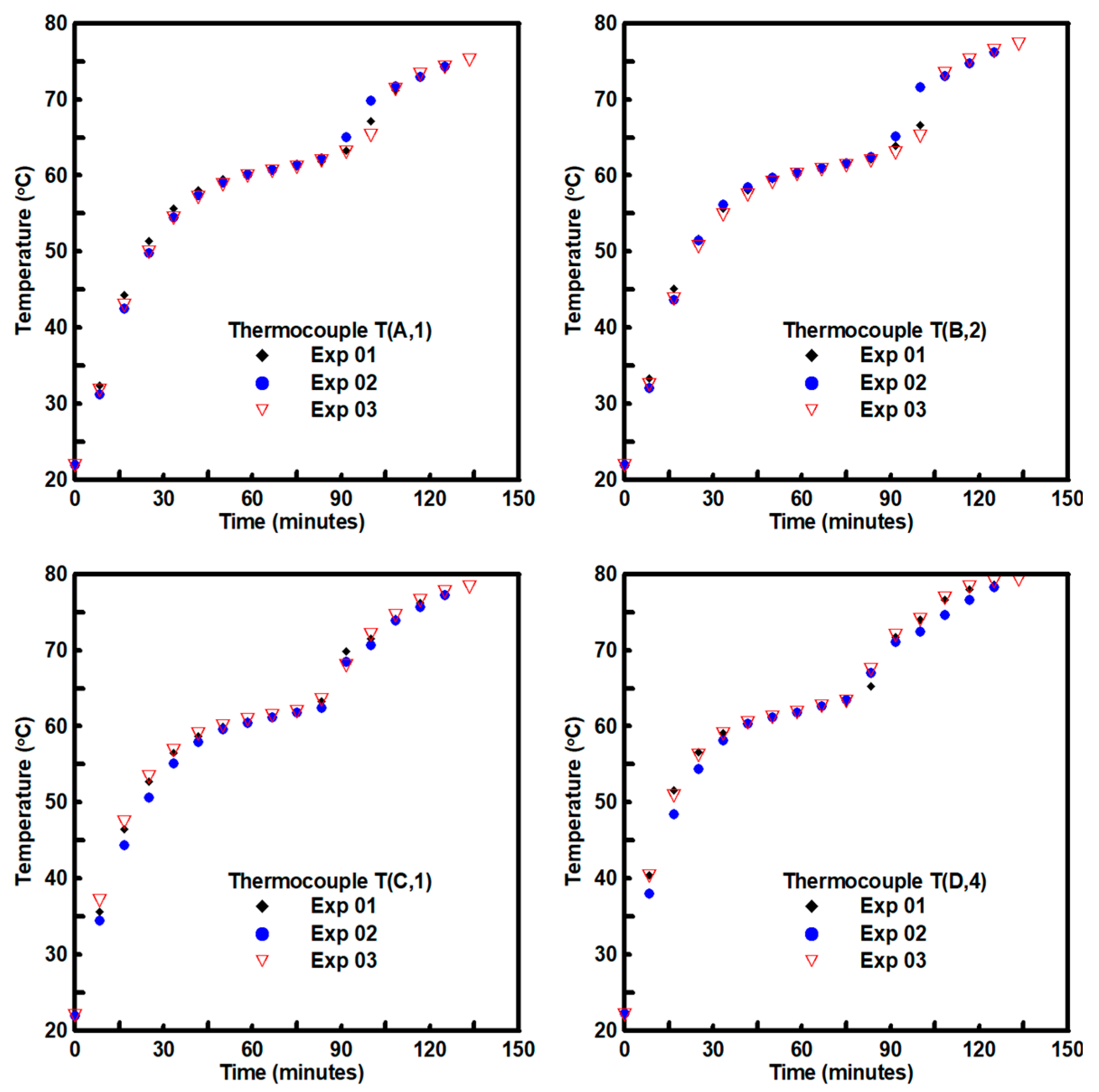
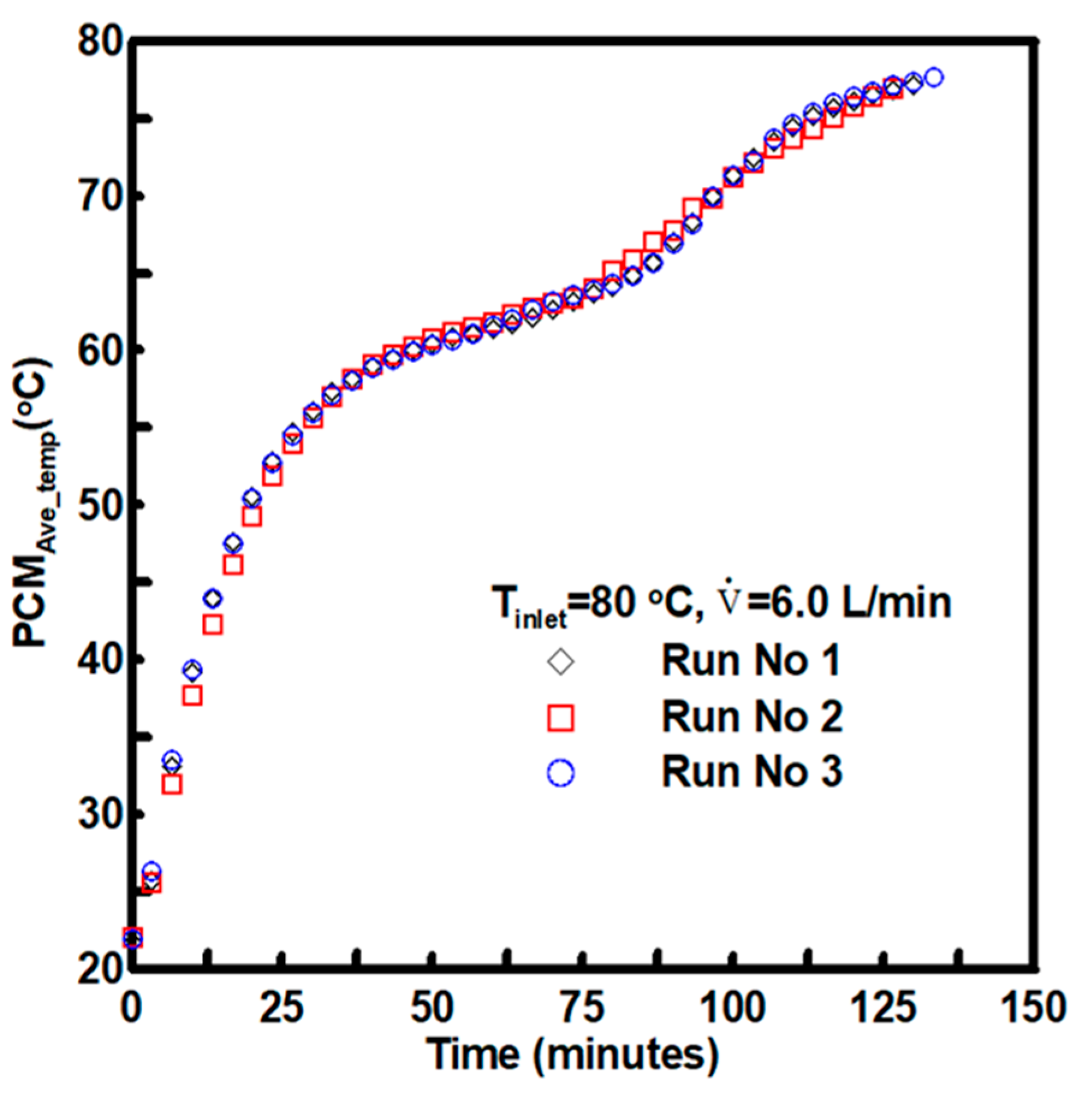
3.1. Experimental Reliability and Repeatability

Three store charging experiments were initially performed at HTF volume flow rate of 6.0 L/min and Tinlet = 80 °C to illustrate the reliability of experimental results.
From Figure 3 and Figure 4, it can be seen that the temporal temperatures variations by four thermocouples inside the PCM store [T (A,1), T (B,2), T (C,3), and T (D,4)] and the PCMAve_temp were nearly identical for each test. The experimental apparatus and procedure clearly produce repeatable results. Due to a marginal variation in PCM initial temperature and inlet HTF temperature.

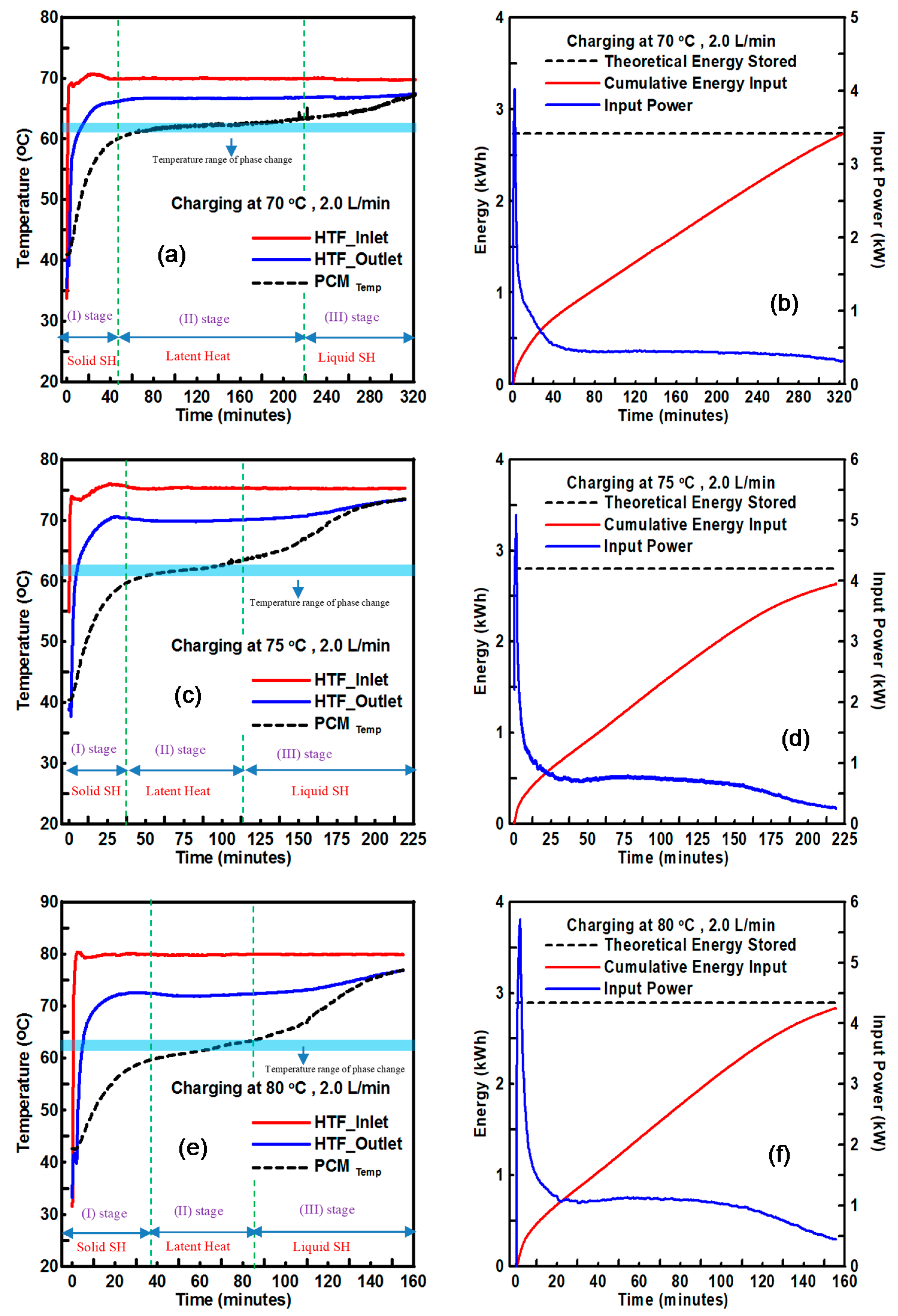
3.2. Charging Process

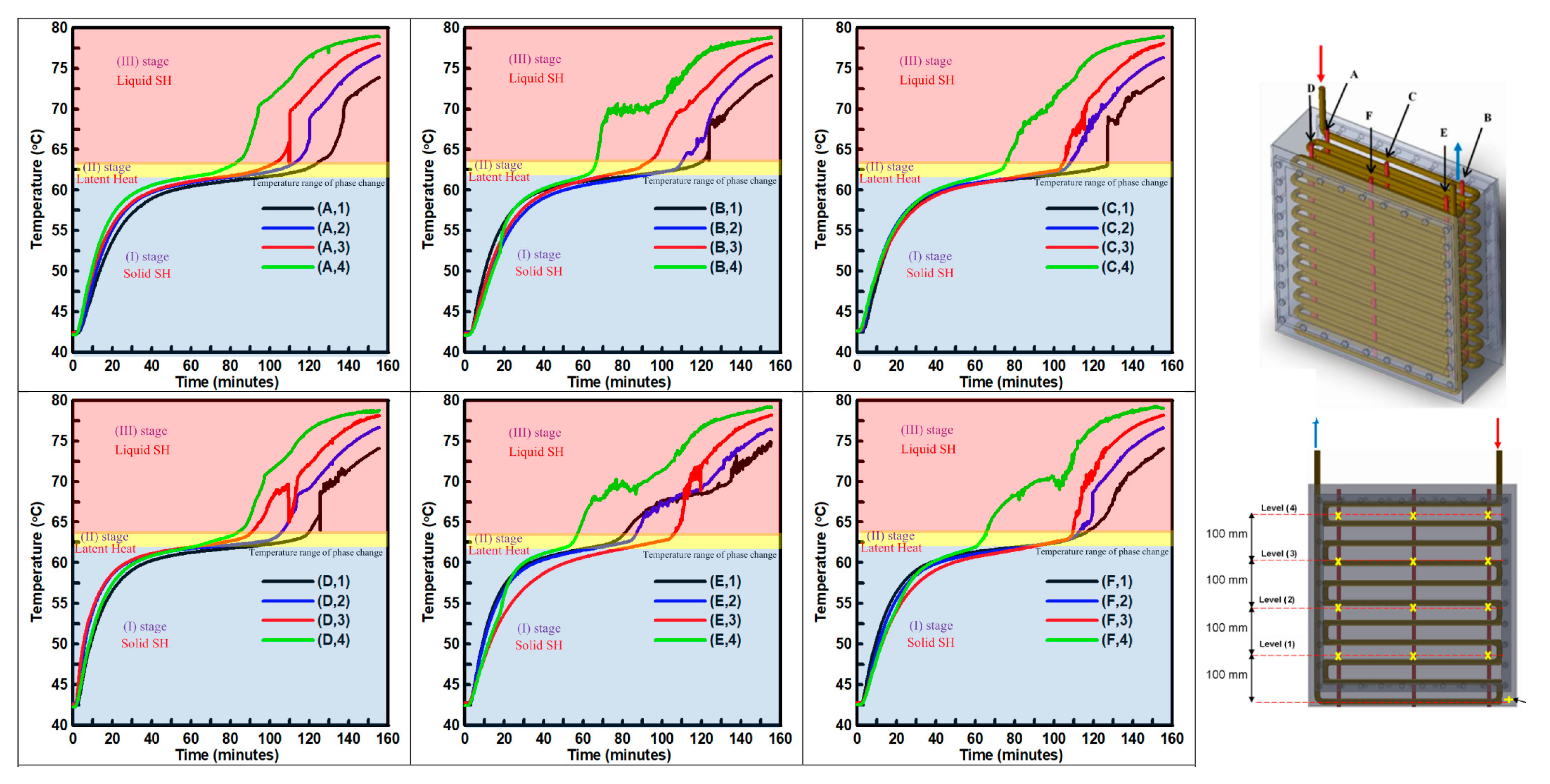
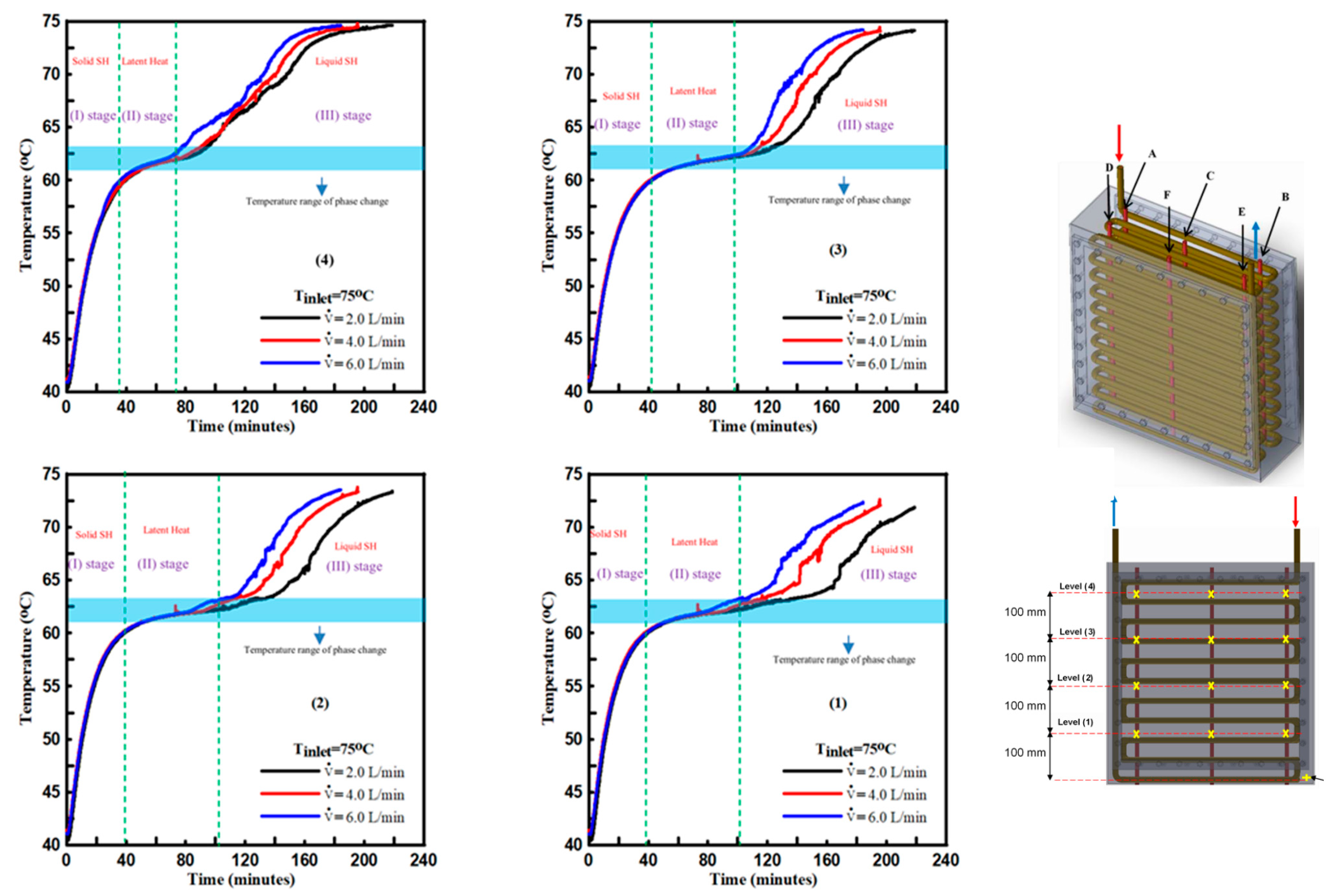
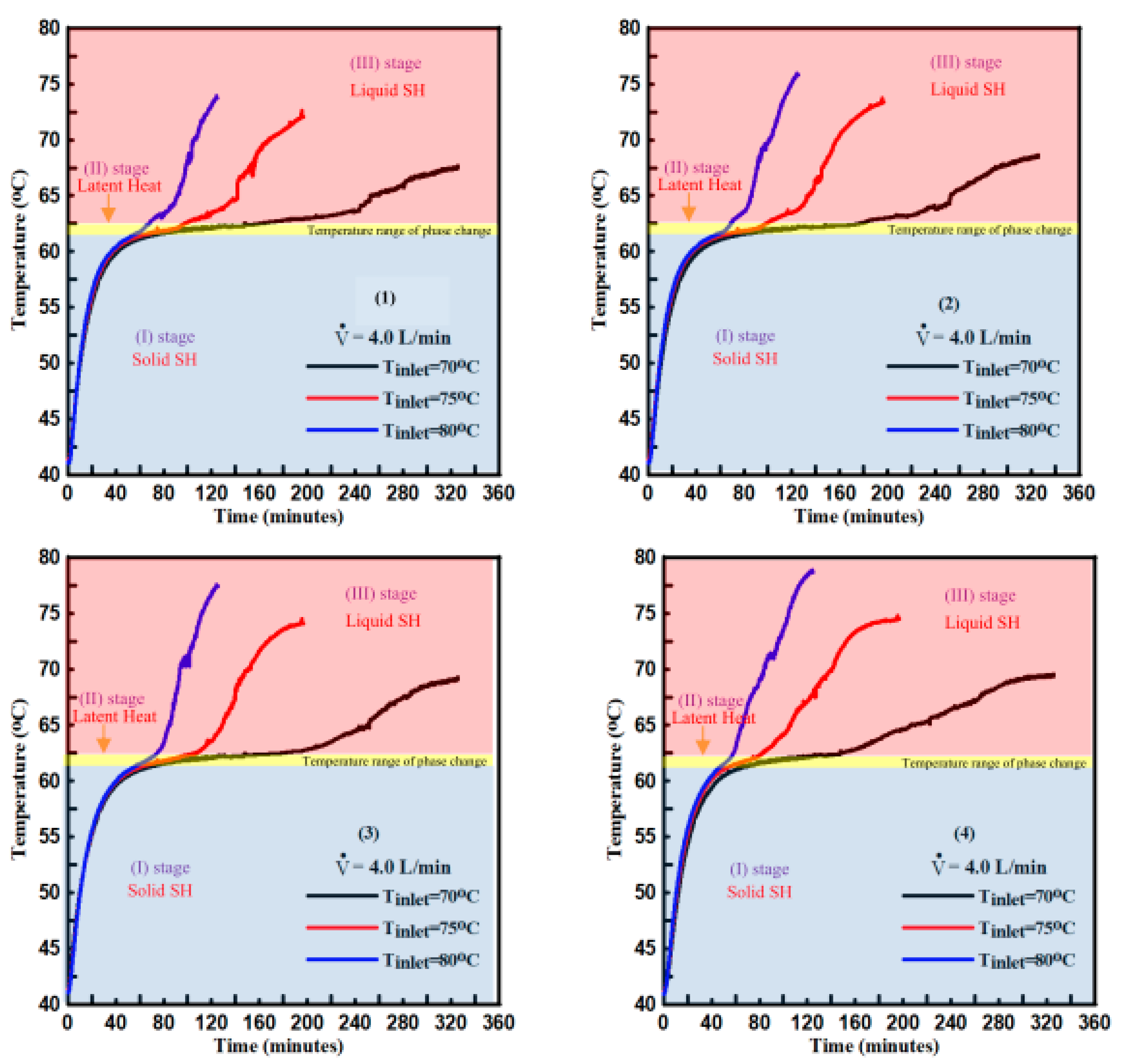
3.2.1. Zonal Temperature Evaluation during the Charging Process

The variation of PCM temperature with time in the LHTESS at four vertical positions in each of the six zones (A, B, C, D, E, and F) during the charging process are presented in Figure 5. The HTF supplied from the hot water storage tank at 80 °C was pumped through the HX in the LHTESS with a constant HTF volume flow rate of 2.0 L/min.
For the current thermal energy store configuration, it can be seen that the PCM temperature at different levels reaches the melting temperature at different times, the time needed for the PCM to melt for the lower level is longer than that of the upper ones, and a vertical temperature gradient in the liquid PCM is evident from the thermocouples in the upper level measuring higher temperatures than those in the lower-levels as a result of natural convection.
The charging process can be categorized into three stages [6,24,25,35]:
Stage (I) sensible heat storage in the solid PCM with heat transfer by conduction and the solid PCM temperature increases linearly. In this stage, there is no big difference among the temperature for various locations.
Stage (II) latent heat storage in the PCM during solid/liquid phase change with heat transfer by conduction in the solid PCM and conduction and convection in the liquid PCM. As the latent heat capacity of the PCM is much greater than the sensible heat capacity of the solid PCM, the rate of increase in PCM temperature reduces when the temperature approaches the phase change temperature.
Stage (III) sensible heat storage in the liquid PCM above the phase change temperature with heat transfer by conduction and natural convection. In this stage, the PCM temperature rises rapidly with heat transfer dominated by natural convection. The measured temperatures at every thermocouple location can be seen to diverge, with the effect of thermocouple height being evident.
The timing of the transitions between the stages varies according to the PCM zones location relative to the HTF temperature in the HX and the height within the store.

3.2.2. Effect of Operational Parameters

HTF Volume Flow Rate

A parametric analysis was performed to evaluate the effect of different HTF volume flow rate on the changing time was conducted with HTF volume flow rates of 2.0, 4.0, and 6.0 L/min. The system was charged using a fixed inlet temperature of 75 °C.
It can be seen from Figure 6a,c,e that during sensible heat storage in the solid PCM, the HTF outlet temperature initially rises rapidly, reaches a constant value during the latent heat storage stage, and then again increases towards the HTF inlet temperature, when the heat is being stored as sensible heat in the melted PCM.
Figure 6b,d,f present the evaluated transient charging input power for three tested HTF volume flow rates. At the start of the charging process, Tinlet was 75 °C, while Tout was close to the PCM initial temperature. The results show that the transient charging input power was high at the beginning of the experiment due to the considerable difference between measured Tin and Tout, this was, however, due to flushing of the cold HTF out of the HX. The transient charging input power then decreased sharply and reflects the heat transfer to storage. Towards the end of the charging process, the transient charging input power diminishes when the PCM is completely melted.
The total cumulative thermal energy stored for the three-charging process are presented in Figure 6b,d,f. The results show that the amount of thermal energy stored for this experiment was 2.85 ± 0.05 kWh and is closely aligned with the theoretical storage capacity of 2.85 kWh. The total charging time to charge the thermal store from an average temperature of 40–73 °C was 219 min for a volume flow rate of 2.0 L/min, 195 min for HTF volume flow rate 4.0 L/min, and 184 min for volume flow rate 6.0 L/min.
Figure 7 presents the time varying PCM average temperatures for four heights in the LHTESS for three different HTF volume flow rates. The measured PCM temperatures were averaged in the horizontal plane to allow comparison of temperatures in the vertical direction.
The first observation from this Figure is that in Stage (I) while charging at Tinlet of 75 °C, varying HTF volume flow rate does not enhance heat transfer in the initial stages of the charging process when conduction is the dominant mode of heat transfer in the PCM. The low thermal conductivity of the solid PCM provides high thermal resistance to heat transfer and thus limits the overall heat transfer rate [24,25].
As shown in Figure 7, the total charging time to charge the thermal store from an average temperature of 40–73 °C was 219 min for HTF volume flow rate of 2.0 L/min, 195 min for HTF volume flow rate 4.0 L/min, and 184 min for HTF volume flow rate 6.0 L/min.

HTF Inlet Temperature

The effect of varying HTF inlet temperature on the overall charging process was conducted at varied HTF of temperatures 70, 75, and 80 °C. The HTF volume flow rate was set constant to 2.0 L/min. As shown in Figure 8a–f the HTF inlet temperature has a significant impact on the LHTESS thermal performance with a significant increase in heat transfer rate observed when increasing the HTF inlet temperature [24,25,35]. The higher HTF inlet temperature provides a larger temperature difference between the PCM and the HTF. The pipe surface temperature rises more quickly transferring more heat to the PCM, which leads to faster melting at the beginning of the charging process.
The experimental results show that for a constant HTF volume flow rate of 2.0 L/min, increasing HTF inlet temperature from 70 to 75 °C and 80 °C decreased the total melting time by 32.6% and 52.3%, respectively. The increase in HTF inlet temperature leads to increased sensible stored heat after phase transition resulting in an increase in the overall heat stored.
Figure 9 shows the influence of HTF inlet temperature (a key parameter in determining the Stefan number) on the PCM average temperatures at four heights in the LHTESS during the charging process for a fixed HTF volume flow rate of 4.0 L/min. The experimental results show that during the first 60 min of the charging process, it can be observed that the variation of the PCM average temperatures with time follows similar trends due to the domination of conduction heat transfer.
Once the PCM temperature reaches the melting temperature, it is clear that the Stefan number has a significant impact on the phase transition rate. By increasing the Stefan number, the temperature difference between PCM and HTF increases which leads to a higher rate of heat transfer and a consequent increase in heat transfer to the PCM. By increasing the Stefan number, the melting rate increases with rapid phase transition from solid to liquid [36].
It can be concluded that the consequence of increasing the HTF inlet temperature is more significant compared to increasing the HTF volume flow rate, i.e., increasing the Stefan number has a larger effect than increasing the Reynolds number. For many applications, the maximum inlet temperature is however set by the process and may be restricted to lower values [6,35].

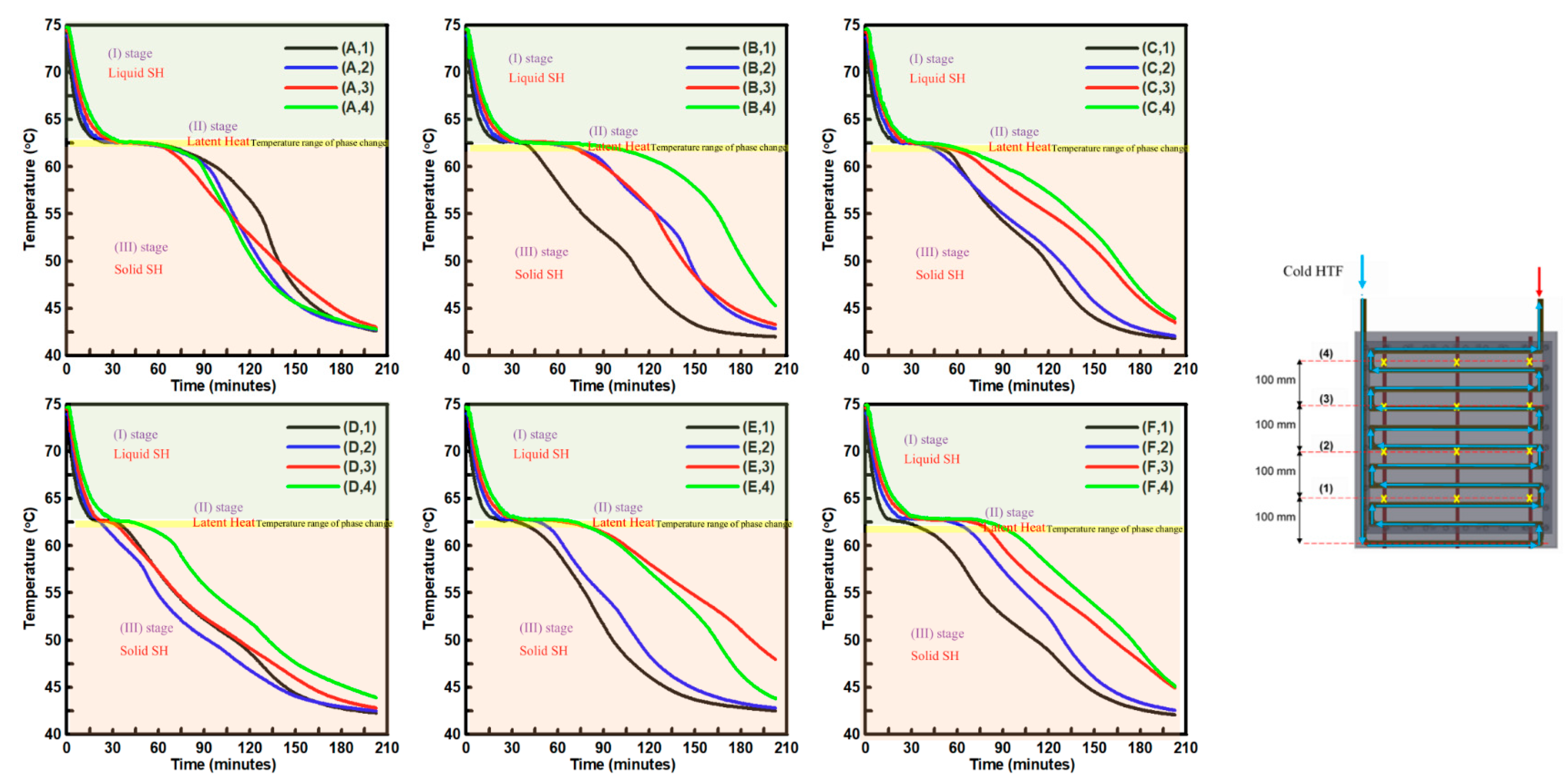
3.3. Discharging Process

In order to investigate the thermal performance of the LHTESS during the discharging process, low-temperature HTF is circulated through the multitube-HX to retrieve thermal energy from high-temperature liquid PCM in the LHTESS. A set of three discharge cycles were conducted at varied HTF volume flow rates of 1.7, 2.3, and 5.1 L/min. Whereas, HTF inlet temperature was set constant to 40 ± 1.0 °C. The PCM initial temperature in the LHTESS (ranging between 70 and 80 °C) was above the PCM melting temperature. During the discharging process, the HTF flow direction through the HX was reversed, so that the cold inlet HTF was pumped into the store from the bottom and hot HTF was discharged from the top.

Zonal Temperature Evaluation during the Discharging Process

Figure 10 presents the time-varying PCM temperatures measured in the LHTESS at four vertical positions in each of the six zones (A, B, C, D, E, and F) during the discharging process with a HTF volume flow rate of 2.3 L/min.
The discharging process can be divided into three stages [6,24,25,35]:
Stage (1) sensible heat extraction from the liquid PCM with heat transfer by both conduction and natural convection.
Stage (II) latent heat extraction with heat transfer by conduction and convection from the PCM leading to the liquid/solid phase change
Stage (III) sensible heat extraction from the solid PCM with heat transfer by conduction. Due to the initial large temperature difference between the liquid RT62HC in the LHTESS store and the cold HTF inlet temperature, sensible heat is extracted rapidly from the liquid PCM RT62HC and the PCM temperature falls to 62.5 °C. The rate of sensible thermal energy discharge from the liquid PCM to the HTF is almost constant with convection dominating the heat transfer process [34]. As shown in Figure 10, during the phase transition stage of the discharge process, the measured temperatures of RT62HC due to the high latent heat capacity were almost constant at 62.5 °C.
When that, PCM started to solidify, a thin layer of PCM (white solid) formed around the tubes of the HX and rapidly discharged a latent portion of thermal energy to the HTF as shown in Figure 11, increasing the thermal resistance and reducing heat transfer from the PCM to the HTF. The reduced rate of heat transfer resulted in a decrease in the rate of PCM phase change from liquid to solid, after solidification of PCM on the HX surface, conduction became the rate-determining heat transfer mechanism for heat removal from the thermal store.
Due to the greater temperature difference between the cold inlet HTF when it enters the store and the PCM in the store at the start of the HX, the rate of heat transfer from the PCM at level (1) is the highest, decreasing in subsequent levels as the HTF temperature increases.
From Figure 10 it can be seen that during the discharge process, in most zones the PCM is thermally stratified, a thermocline is formed with higher temperatures at the top of the store and colder temperatures at the base. During solidification due to the design of the HX, cold fluid entering at the base of the store and hot fluid leaving at the top, natural convection in the liquid PCM was negligible.
Figure 12 shows transient HTF inlet/outlet temperatures, transient PCM average temperature, transient output power, and the total accumulative thermal energy retrieved during the discharging process at varied HTF volume flow rates.
It is clear that the discharge process can also be categorized into three stages [36]. Stage (I), where when cold HTF flows into the LHTESS store and begins to remove the stored heat, at this stage the PCM average temperature decreases rapidly, also, it is observed at this stage, the temperature difference between HTF inlet and outlet water is high, meaning the heat transfer resistance between the PCM and HTF is low and indicates that proposed LHTESS store has high levels of heat exchange between the PCM and HTF which is helped by natural convection in the liquid RT62HC.
In stage (II), during which RT62HC has a stable temperature, a distinct temperature plateau can be seen, indicating the mushy phase change process, in which, the rate of heat exchange between the PCM and HTF is determined by the combined effects of natural-convection thermal conduction heat transfer [35].
In stage (III), the heat exchange rate is dominated by thermal conduction in the solid RT62HC, therefore, the heat transfer from the RT62HC to the HTF gradually decreases. During this stage, the temperature of RT62HC decreases rapidly and the temperature difference between the cold HTF inlet and outlet HTF temperature becomes smaller.
Since the initial PCM initial temperature in the store for the three discharge experiments were not the same being in the range of (70–80 °C), the effects on store discharging cannot be attributed completely to the HTF volume flow rate. However, an increase in HTF volume flow rate will increase the convective heat transfer coefficient within the HX, which will decrease the overall thermal resistance between the PCM and HTF. As seen in Figure 12, the initial rapid decline in HTF outlet temperature is due to flushing hot HTF out of the PCM-HX.
As shown in Figure 12, under constant HTF volume flow rate of 1.7 L/min, the maximum transient discharged power was 4.48 kW then after 52.3 min dropped to 1.0 kW. The calculated thermal energy retrieved from the store was 2.67 kWh and the discharge efficiency of LHTESS prototype is about 93.5%.
When the HTF volume flow rate increased to 2.3 L/min, the discharge power shows a similar trend to that observed for HTF volume flow rate of 1.7 L/min with a peak discharge power output of 5.11 kW with a total of 2.45 kWh of thermal energy discharged from the store with a discharge efficiency of LHTESS prototype of about 90%. For a high-volume flow rate of 5.1 L/min, the maximum power output starts at 8.85 kW and drops to 1.0 kW after 39 min. The amount of heat discharged from the store was 2.27 kWh and the discharge efficiency of LHTESS prototype is about 89%.
With natural convection not playing any significant role during the discharging process and conduction being the heat transfer mechanism determining overall heat transfer rate, it is clear that the HTF volume flow rate does not significantly change the total solidification times as heat transfer is limited by the thermal resistance of the solid PCM layer that forms on the outside the copper pipe. Due to the reduced rates of heat transfer that the solidification of PCM causes the difference between the inlet and outlet HTF temperature decreased and the amount of the energy recovered from the system was similar for all three flow rates, this is in agreement with the findings reported in the literature for several other thermal storage geometries [24,33,35,37,38].

4. Conclusions

An experimental laboratory prototype compact LHTESS using PCM RT62HC with a horizontally oriented multitube HX was built. The store’s thermal performance was evaluated to determine the extent which PCM-HX design would need to be improved to meet domestic hot water supply and space heating demands.
The major conclusions drawn from the experimental study for the store tested were as follows:
  • During the initial stages of the charging process, heat transfer by conduction is the domain mode in the PCM, as the liquid PCM fraction increases, the effect of natural convection was found to be significant.
  • The PCM at the top position of the store melts quickly as compared to central and bottom positions due to natural convection in the PCM and high-temperature liquid PCM rising due to buoyancy forces.
  • However, natural convection was found to be insignificant during the solidification process.
  • An increase in HTF volume flow rate during the charging/discharging process, has decreased both melting/solidification time with the reduction in time more prominent for melting than for solidification.
  • Changing the inlet temperature of the HTF has a greater effect on charging time when compared with the HTF volume flow rate for the range of temperatures and flow rates used.
  • At constant HTF inlet temperature of 70 °C the total melting time is decreased by 10.95% and 16.0% by increasing the HTF volume flow rate from 2.0 to 4.0 L/min and 6.0 L/min, respectively.
  • At a constant volume flow rate of 2.0 L/min, increasing HTF inlet temperature from 70 to 75 °C and 80 °C leads to reductions in total melting time by 32.6% and 52.3%.
  • The total amount of thermal energy heat retrieved from the LHTESS was around 2.47 kWh.
  • The outcomes of the present work provide a foundation for the design and optimization of similar storage design configurations.
  • By using a modular approach LHTESS can form a versatile scalable element for inclusion in larger-scale systems, for example, commercial building waste heat recovery in addition to domestic heating systems

Author Contributions

Conceptualization, M.F. and P.E.; methodology, M.F. and P.E.; formal analysis, M.F.; investigation, M.F. and P.E.; data curation, M.F.; writing—original draft preparation, M.F.; writing—review and editing, M.F. and P.E.; visualization, M.F.; supervision P.E.; project administration, P.E.; funding acquisition, P.E. All authors have read and agreed to the published version of the manuscript.

Funding

This research was funded by Engineering and Physical Sciences Research Council (EPSRC) through The Active Building Centre Research Programme (ABC RP) grant reference EP/V012053/1 and Small Smart Sustainable Systems for future Domestic Hot Water (4S-DHW) Grant reference EP/N021304/1.

Conflicts of Interest

The authors declare no conflict of interest.

References

  1. Pereira, J.; Cunha, D.; Eames, P.; da Cunha, J.P.; Eames, P. Compact latent heat storage decarbonisation potential for domestic hot water and space heating applications in the UK. Appl. Therm. Eng. 2018, 134, 396–406. [Google Scholar] [CrossRef]
  2. BEIS Evidence Gathering: Thermal Energy Storage (TES) Technologies; Department for Business, Energy and Industrial Strategy: London, UK, 2016.
  3. Ding, Y.; Li, Y.; Liu, C.; Sun, Z. Solar Electrical Energy Storage; Elsevier: Amsterdam, The Netherlands, 2015; ISBN 9780124095496. [Google Scholar]
  4. Fadl, M.; Eames, P. A comparative study of the effect of wall heat flux on melting and heat transfer characteristics in phase change material thermal energy stores arranged vertically and horizontally. In Proceedings of the 9th Edition of the International SOLARIS Conference; IOP Conference Series; Materials Science and Engineering (MSE): Chengdu, China, 2018. [Google Scholar]
  5. Huang, H.; Xiao, Y.; Lin, J.; Zhou, T.; Liu, Y.; Zhao, Q. Improvement of the efficiency of solar thermal energy storage systems by cascading a PCM unit with a water tank. J. Clean. Prod. 2020, 245, 118864. [Google Scholar] [CrossRef]
  6. Kabbara, M.; Groulx, D.; Joseph, A. Experimental investigations of a latent heat energy storage unit using finned tubes. Appl. Therm. Eng. 2016, 101, 601–611. [Google Scholar] [CrossRef]
  7. Saeed, R.M.; Schlegel, J.P.P.; Sawafta, R.; Kalra, V. Plate type heat exchanger for thermal energy storage and load shifting using phase change material. Energy Convers. Manag. 2019, 181, 120–132. [Google Scholar] [CrossRef]
  8. Riahi, S.; Saman, W.Y.; Bruno, F.; Belusko, M.; Tay, N.H.S. Impact of periodic flow reversal of heat transfer fluid on the melting and solidification processes in a latent heat shell and tube storage system. Appl. Energy 2017, 191, 276–286. [Google Scholar] [CrossRef]
  9. Agyenim, F.; Eames, P.; Smyth, M. Heat transfer enhancement in medium temperature thermal energy storage system using a multitube heat transfer array. Renew. Energy 2010, 35, 198–207. [Google Scholar] [CrossRef]
  10. Kalapala, L.; Devanuri, J.K. Influence of operational and design parameters on the performance of a PCM based heat exchanger for thermal energy storage—A review. J. Energy Storage 2018, 20, 497–519. [Google Scholar] [CrossRef]
  11. Egea, A.; Solano, J.P.; Pérez-García, J.; García, A. Solar-driven melting dynamics in a shell and tube thermal energy store: An experimental analysis. Renew. Energy 2020, 154, 1044–1052. [Google Scholar] [CrossRef]
  12. Pakalka, S.; Valančius, K.; Streckienė, G. Experimental comparison of the operation of PCM-based copper heat exchangers with different configurations. Appl. Therm. Eng. 2020, 172, 115138. [Google Scholar] [CrossRef]
  13. Osman, M.; Abokersh, M.H.; El-Baz, O.; Sharaf, O.; Mahmoud, N.; El-Morsi, M. Key performance indicators (KPIs): Assessing the process integration of a shell-and-tube latent heat storage unit. J. Clean. Prod. 2020, 256. [Google Scholar] [CrossRef]
  14. Yazici, M.Y.; Avci, M.; Aydin, O.; Akgun, M. On the effect of eccentricity of a horizontal tube-in-shell storage unit on solidification of a PCM. Appl. Therm. Eng. 2014, 64, 1–9. [Google Scholar] [CrossRef]
  15. Yusuf Yazici, M.; Avci, M.; Aydin, O.; Akgun, M. Effect of eccentricity on melting behavior of paraffin in a horizontal tube-in-shell storage unit: An experimental study. Sol. Energy 2014, 101, 291–298. [Google Scholar] [CrossRef]
  16. Saydam, V.; Parsazadeh, M.; Radeef, M.; Duan, X. Design and experimental analysis of a helical coil phase change heat exchanger for thermal energy storage. J. Energy Storage 2019, 21, 9–17. [Google Scholar] [CrossRef]
  17. Seddegh, S.; Tehrani, S.S.M.; Wang, X.; Cao, F.; Taylor, R.A. Comparison of heat transfer between cylindrical and conical vertical shell-and-tube latent heat thermal energy storage systems. Appl. Therm. Eng. 2018, 130, 1349–1362. [Google Scholar] [CrossRef]
  18. Meng, Z.N.; Zhang, P. Experimental and numerical investigation of a tube-in-tank latent thermal energy storage unit using composite PCM. Appl. Energy 2017, 190, 524–539. [Google Scholar] [CrossRef]
  19. Avci, M.; Yazici, M.Y. Experimental study of thermal energy storage characteristics of a paraffin in a horizontal tube-in-shell storage unit. Energy Convers. Manag. 2013, 73, 271–277. [Google Scholar] [CrossRef]
  20. Seddegh, S.; Wang, X.; Henderson, A.D. A comparative study of thermal behaviour of a horizontal and vertical shell-and-tube energy storage using phase change materials. Appl. Therm. Eng. 2016, 93, 348–358. [Google Scholar] [CrossRef]
  21. Kousha, N.; Hosseini, M.J.; Aligoodarz, M.R.; Pakrouh, R.; Bahrampoury, R. Effect of inclination angle on the performance of a shell and tube heat storage unit—An experimental study. Appl. Therm. Eng. 2017, 112, 1497–1509. [Google Scholar] [CrossRef]
  22. Kalapala, L.; Devanuri, J.K. Energy and exergy analyses of latent heat storage unit positioned at different orientations—An experimental study. Energy 2020, 194, 116924. [Google Scholar] [CrossRef]
  23. Ghani, F.; Waser, R.; O’Donovan, T.S.; Schuetz, P.; Zaglio, M.; Wortischek, J. Non-linear system identification of a latent heat thermal energy storage system. Appl. Therm. Eng. 2018, 134, 585–593. [Google Scholar] [CrossRef]
  24. Fadl, M.; Eames, P.C. An experimental investigation of the heat transfer and energy storage characteristics of a compact latent heat thermal energy storage system for domestic hot water applications. Energy 2019, 188, 116083. [Google Scholar] [CrossRef]
  25. Fadl, M.S.; Eames, P.C. An experimental investigation of the heat transfer and energy storage characteristics of a latent heat thermal energy storage system with a vertically-oriented multi-pass tube heat exchanger for domestic hot water applications. In Eurotherm Semin. #112 Adv. Therm. Energy Storage; 2019; Available online: https://repository.lboro.ac.uk/articles/An_experimental_investigation_of_the_heat_transfer_and_energy_storage_characteristics_of_a_latent_heat_thermal_energy_storage_system_with_a_vertically-oriented_multi-pass_tube_heat_exchanger_for_domestic_hot_water_applications/9549371 (accessed on 30 October 2020).
  26. T4+, F.® Foamglas ® t4+. Available online: https://www.foamglas.com/en-gb/products/fgbt4slabs (accessed on 9 December 2019).
  27. FT-110 Series TurboFlow; Turbine Electronic Flow Sensors. Available online: https://www.gemssensors.co.uk/flow/electronic-flow-sensors/turbo-flow/ft-110-series-flow-sensor (accessed on 14 December 2018).
  28. DataTaker-DT85 Data Logger. Available online: http://www.datataker.com/DT85.php (accessed on 2 February 2018).
  29. Le, K.X.; Huang, M.J.; Shah, N.; Wilson, C.; Artain, P.M.; Byrne, R.; Hewitt, N.J. High temperature air source heat pump coupled with thermal energy storage: Comparative performances and retrofit analysis. In Proceedings of the Energy Procedia; Elsevier Ltd.: Amsterdam, The Netherlands, 2019; Volume 158, pp. 3878–3885. [Google Scholar]
  30. Nallusamy, N.; Sampath, S.; Velraj, R. Experimental investigation on a combined sensible and latent heat storage system integrated with constant/varying (solar) heat sources. Renew. Energy 2007, 32, 1206–1227. [Google Scholar] [CrossRef]
  31. Kingspan Thermomax DF400 Evacuated Tube Collectors, Kingspan. Available online: https://www.kingspan.com/gb/en-gb/products/renewable-technologies/solar-thermal/solar-evacuated-tube-collectors/thermomax-hp400-evacuated-tube-collectors (accessed on 26 March 2019).
  32. Rubitherm GmbH. Available online: https://www.rubitherm.eu/ (accessed on 21 February 2018).
  33. Liu, C.; Groulx, D. Experimental study of the phase change heat transfer inside a horizontal cylindrical latent heat energy storage system. Int. J. Therm. Sci. 2014, 82, 100–110. [Google Scholar] [CrossRef]
  34. Anish, R.; Mariappan, V.; Joybari, M.M.; Abdulateef, A.M. Performance comparison of the thermal behavior of xylitol and erythritol in a double spiral coil latent heat storage system. Therm. Sci. Eng. Prog. 2020, 15, 100441. [Google Scholar] [CrossRef]
  35. Kabbara, M.; Groulx, D.; Joseph, A. A parametric experimental investigation of the heat transfer in a coil-in-tank latent heat energy storage system. Int. J. Therm. Sci. 2018, 130, 395–405. [Google Scholar] [CrossRef]
  36. Khan, Z.A.Z.; Khan, Z.A.Z. Experimental investigations of charging/melting cycles of paraffin in a novel shell and tube with longitudinal fins based heat storage design solution for domestic and industrial applications. Appl. Energy 2017, 206, 1158–1168. [Google Scholar] [CrossRef]
  37. Li, T.X.; Xu, J.X.; Wu, D.L.; He, F.; Wang, R.Z. High energy-density and power-density thermal storage prototype with hydrated salt for hot water and space heating. Appl. Energy 2019, 248, 406–414. [Google Scholar] [CrossRef]
  38. Murray, R.E.; Groulx, D. Experimental study of the phase change and energy characteristics inside a cylindrical latent heat energy storage system: Part 1 consecutive charging and discharging. Renew. Energy 2014, 62, 571–581. [Google Scholar] [CrossRef]
Figure 1. Schematic diagram of the Low-Temperature Lab-Scale Thermal Energy Storage Test Facility at Loughborough University [24].
Energies 13 06193 g001
Figure 2. Diagrams illustrating the design of the thermal energy storage unit. (A) Thermocouple location details within the storage unit, (B) 3D rendering of the LHTESS, (C) the realized system showing the observation window, (D) photograph of the whole thermal energy storage unit with insulation, (E) photograph of the HX prior to insertion, and (F) details of the HX dimensions.
Energies 13 06193 g002
Figure 3. Experimentally measured temperatures during charging process at four different thermocouple positions T (A,1), T (B,2), T (C,3), and T (D,4) for three different experiments (Tinlet = 80 °C and V · = 6.0 L/min).
Energies 13 06193 g003
Figure 4. Comparison of PCM average temperature for three experiments during the charging process (Tinlet = 80 °C and V · = 6.0 L/min).
Energies 13 06193 g004
Figure 5. Comparison of PCM measured temperatures during a charging process at all six zones. Tinlet = 80 °C and V · = 2.0 L/min.
Energies 13 06193 g005
Figure 6. Transient HTF inlet/outlet temperatures, PCM average temperature, input power, and accumulative thermal energy stored during the charging process at varied HTF flow rates of 2.0, 4.0, and 6.0 L/min and Tinlet = 75 °C.
Energies 13 06193 g006
Figure 7. Time-varying average temperatures of thermocouple measurements at the upper level (4), central upper level (3), central lower level (2), and lower level (1) during the charging process for three different HTF volume flow rates and Tinlet = 75 °C.
Energies 13 06193 g007
Figure 8. Transient HTF inlet/outlet temperatures, PCM average temperature, input power, and accumulative thermal energy stored during the charging process at varied HTF Tinlet = 70, 75, and 80 °C and V · = 2.0.
Energies 13 06193 g008
Figure 9. Average temperature variation with time for thermocouples located at the upper position (4), central upper position (3), central lower position (2), and lower position (1) during the charging process for three different HTF Tinlet, and V · = 40 L/min.
Energies 13 06193 g009
Figure 10. Measured PCM temperatures during a store discharge process at all six zones and four vertical positions within each zone. Tinlet = 40 °C and V · = 2.3 L/min.
Energies 13 06193 g010
Figure 11. A photograph showing the solidification of the PCM on the tubes in the LHTESS during the discharging process.
Energies 13 06193 g011
Figure 12. Transient HTF inlet/outlet temperatures, PCM average temperature, output power, and accumulative thermal energy retrieved during the discharging process at varied HTF volume flow rate of 1.7, 2.3, and 5.1 L/min and Tinlet = 40 °C.
Energies 13 06193 g012
Table 1. Thermophysical properties of paraffin wax RT62HC [32].
PropertyValueDimension
Melting temperature62–63°C
Congealing temperature62°C
Heat storage capacity, in a temperature range of 55 °C to 70 °C230kJ/kg
Density at 25 °C (solid)850kg/m3
Density at 80 °C (liquid)840kg/m3
Specific heat capacity (solid/liquid)2000J/(kg∙°C)
Thermal conductivity (solid/liquid)0.2W/(m∙°C)
Table 2. Calculated Reynolds number for flow rates and fluid temperatures used in charge and discharge conditions.
HTF Inlet Temperature (°C)Volume Flow Rate (L/min)ReD
Charging7027738
7528242
8028745
70415,477
75416,485
80417,490
70623,215
75624,727
80626,236
Discharging401.74138
402.35599
405.112,415
Table 3. Stefan number for different HTF inlet temperatures.
HTF Inlet Temperature (°C)Stefan Number (Ste)
Charging process700.077
750.128
800.178
Discharging process40 ± 1.00.225
Publisher’s Note: MDPI stays neutral with regard to jurisdictional claims in published maps and institutional affiliations.

