1. Introduction
Considering aviation drives the weight balance besides reliability and economic feasibility is an essential figure for the system design. A drive system in an aircraft, like in any other vehicle, comprises the electrical machine, the power electronics, and the cooling system. As electrical machines usually are composed of comparably heavy materials, as iron and copper, it is the ambition of the designer to increase the utilization of these materials to an optimized level. The levers are the saturation flux density of the iron lamination, which depends on material quality, and the current density as a design figure. Higher chosen current density results in lower copper weight and higher losses. Evidently, there is a functional dependency between losses, temperatures, and investment into the cooling system. That is the reason why an optimal current density must exist as a function of the cooling system design where the drive system weight reaches a minimum. This function is the aim of the research work presented here in an exemplary design study.
Assuming a single-aisle short-range aircraft (approx. 100 passengers per airplane PAX) in a standard tube and wing configuration with two drives in nacelles and an electric energy supply (battery, turbine-generator set, or fuel cell), a comprehensive study of the thermal dependencies in the drive and cooling system was conducted. In this study, an improved direct slot cooling of a permanent magnet excited electrical machine, as proposed in Reference [
1], in combination with an electrically isolating heat transfer fluid on polysiloxan basis [
2] is assumed for the cooling system, allowing very effective heat removal from the electrical machine. Regarding the power electronics, weight data and efficiencies for a two-level inverter are used. As cooler for heat rejection to the ambiance, a surface cooler is studied, which has a minimal contribution to the drag [
3]. The weight of pumps and piping is estimated based on commercial data. From the calculated losses and the temperatures in the components, the necessary size of the cooler and the system weight are calculated as a function of the current density, thus, enabling a weight balance of the drive system.
There has been a lot of detailed work carried out to study thermal aspects of the design of electrical machines for aviation and automotive applications. In Reference [
4], a direct liquid cooling is studied with stranded conductors wound around a steel tube, thus, forming a conductor. Cooling liquid is a standard water-glycol mixture. The additional losses, due to eddy currents in the steel tube, have to be added to the copper losses. In Reference [
5], an indirect slot cooling is proposed with cooling channels made in a rather complicated molding process with walls of a thin polyimide film, which is thermal closely coupled with the winding during impregnation. In Reference [
6], a process to mold these cooling channels forming a ring-tube construction for later insertion into the free spaces between two phases of a single tooth winding is proposed. Additional weight is saved because no water jacket is necessary in the housing. But due to tolerances in the winding, the thermal coupling of the cooling channel will be reduced by a thicker layer of impregnating resin. In Reference [
7], a conventional water jacket cooling system is optimized by better potting materials, while the power electronics components were integrated into the water jacket. This will require moderate coolant temperatures with respect to the thermal limits of the power electronics resulting in a larger and heavier heat exchanger. In Reference [
8], a heat pump is proposed to increase the temperature of an oil cooling system to achieve smaller and lighter coolers. The authors also realize the problems with the additional weight of the heat pump components, as also mentioned in Reference [
1]. Nevertheless, this may be an option in some special cases. In an overview paper, Reference [
9], the authors mention several cooling methods, such as heat pipe cooling, interwinding cooling, or intrawinding cooling. The direct slot cooling proposed here is an improved easy to manufacture variant of interwinding cooling. The papers [
10,
11] investigate oil spray cooling and air cooling of the electrical machine without closing the complete cooling loop. In Reference [
12], the properties of potted Litz wire and its influence on the temperature situation in the winding were studied theoretically and experimentally. These results have been used in the thermal simulations performed here.
A more system-oriented study is presented in Reference [
13]. The authors performed an exemplary study of a tilt-wing vertical takeoff and landing (VTOL), 15 PAX plane, with respect to the thermal management system. Ram air is used for cooling. A cross flow heat exchanger with a puller fan is provided. The calculations are focused on the heat exchanger design, neglecting further investigation on the influence of the design of the electrical machines. In Reference [
14], the electric on-board system of a more electric aircraft with conventional turbines, but many electrical auxiliary systems is studied. The focus is set here on a fuel cell, and the electrolyzer combination able to handle also regenerative power within the electrical system. In the comprehensive study [
15] a fully electric drive system of an AIRBUS size plane with superconducting machines and liquid hydrogen (LH2) cooling is analyzed. The electrical energy supply is provided by turbo generators fueled with LH2. The electrical motors drive a fan via a gearbox. The focus is set on the holistic modeling of the complete electrical system and its weight balance. This does not match with the conventional drive approach of the paper presented here, but it could be a module in an analog holistic approach of an all-electric aircraft with conventional drives. To the best of the authors’ knowledge, no study was found comprising an analysis of the complete conventional drive system.
2. Calculation Approaches
The scientific analysis of the electric propulsion drives is based on analytical and numerical models, which have been developed by the authors. The aim was to be able to examine a range of electric drive systems with a set of parameters. All calculation-models at this stage of our research represent normal conducting machines incorporating direct conductor cooling. Superconducting machines are subject to prospective research, which will be presented in further publications.
The challenge was to set up fast calculating analytical models to represent the electric motor with a liquid cooling system and to combine this with a FEM-model of the thermal situation in the machine slot to obtain systematic data of the drive-system, including machine weight, machine losses, cooling, heat release, and cooling system weight. Furthermore, an analytical thermal network for the motor has been developed, as shown in Reference [
5]. The results of these calculations show the range of the optimum system weight and yield information on machine losses.
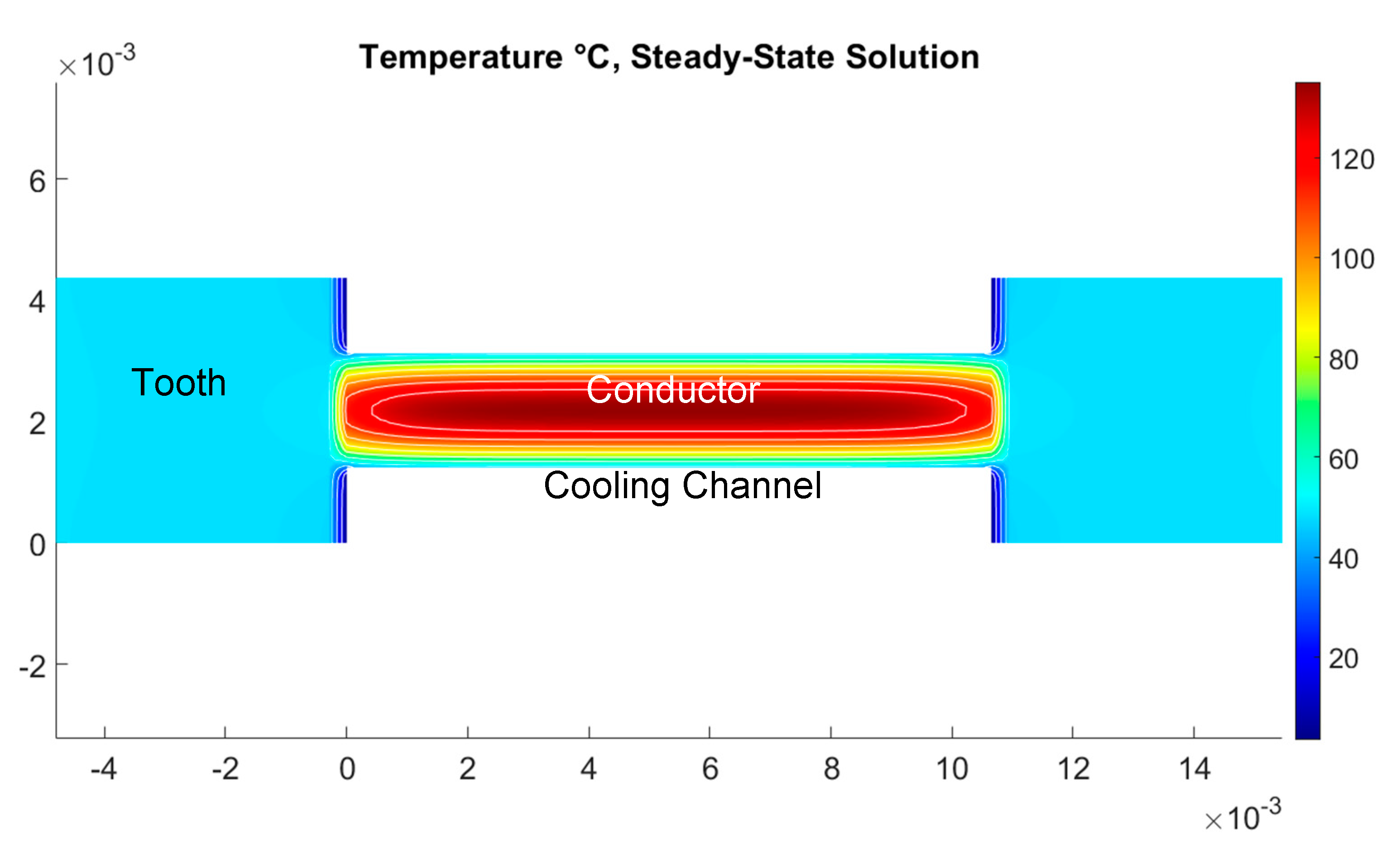
Figure 1 shows the cooling situation in the slot of the machine, which is represented by the model. The liquid is pumped through the stator-slots to remove the heat of the conductors as they are the major locations of heat generation. As to provide a technologically-feasible solution, a sealing has to be provided to the air-gap of the rotor bore.
The thermal situation inside the slot has been investigated by a 2D-FEM-model, which can also be employed for fast, automated calculations with varying geometry, as is shown in
Figure 2. The model represents a cross-section of the slot, including the current conductor in the center.
The cooling channels are embodied by the white areas above and below the conductor. Areas left and right of the conductor are part of the teeth in that area. The model includes slot insulation and conductor insulation, all end winding-losses are transferred to the conductor in the slot.
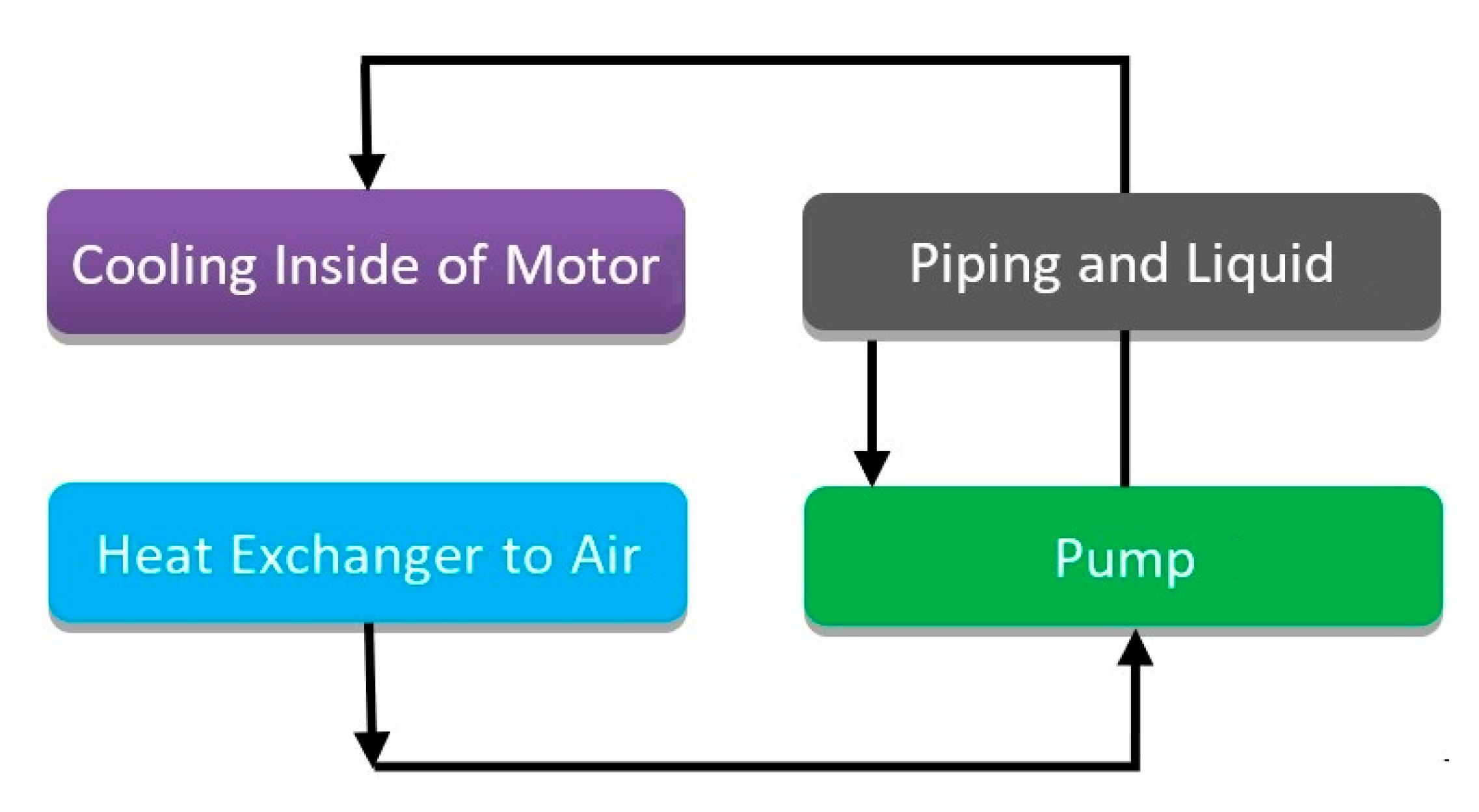
The object of the calculations is a drive system with forced fluid cooling, as depicted in
Figure 3. Motor and heat exchanger are connected by a fluid cycle, which is driven by a pump. The model considers height and speed-dependent environmental conditions.
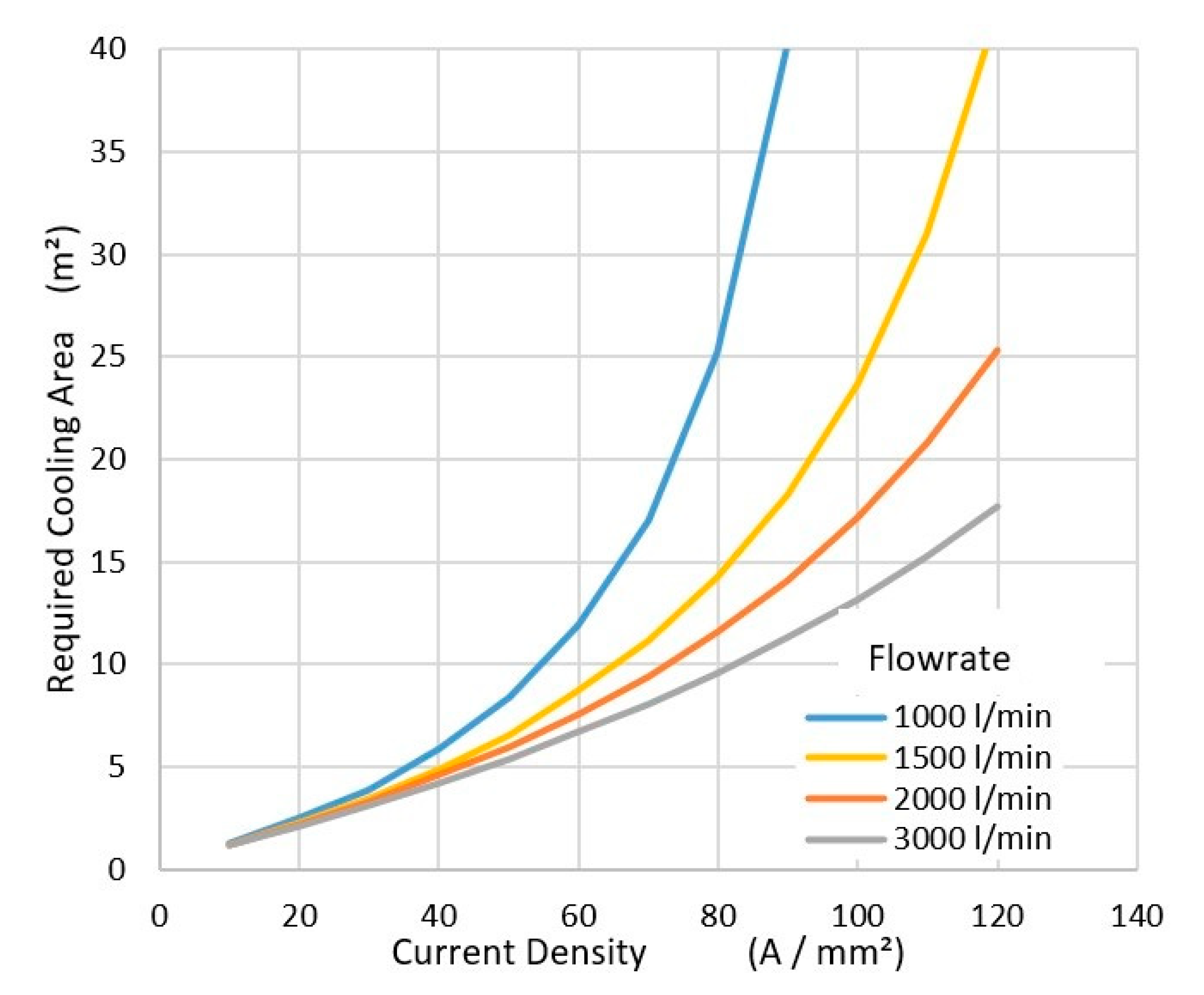
As the mathematical toolchain provides the possibility to simulate the whole liquid cooling cycle, several investigations can be performed. Of special interest are the heat exchangers in the cooling circuit. These are investigated in detail in chapter 7, but here some principal considerations shall be presented. In the example shown in
Figure 4, the aim was to calculate the required cooling area for a 2 MW electric machine fitted with copper conductors. A plane cooler without fins was assumed here. The diagram shows the impact of the flow-rate of the cooling fluid on the system. As the flow rate increases, the required cooling area decreases for given current density and losses. The reason for this is a smaller temperature drop in the cooling circuit, allowing a higher cooling medium temperature level, which results in a larger temperature-difference to the environment.
This is restricted by the permitted pressure in the system and the provided pump-power. By using fins, the required base-area for the cooler on the aircraft can be reduced further, but for the price of increased drag.
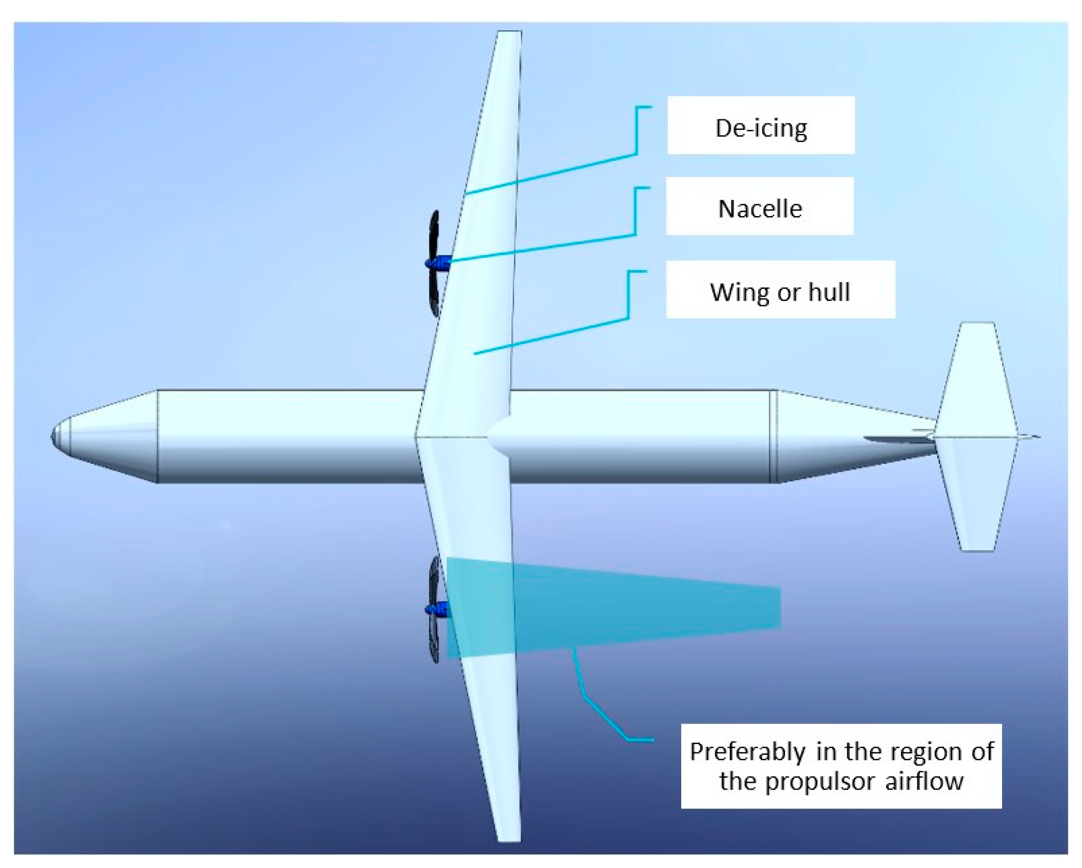
Another restriction is the heat transfer coefficient to the surrounding air. The dominating factor of this coefficient is the air-speed and the laminar to turbulent properties of the air boundary layer. To not complicate the results of this study too much, it was assumed that the cooler is integrated into the wing structure. An interesting alternative is to place the cooler in the fast-flowing air behind the propulsor and to assume that the surface enhances turbulent flow. This may result in another restriction: If the required areas exceed the available high-speed air areas, a splitting of the cooler is necessary, and a part of the cooler must be integrated into the wing or hull—this will be the subject of further studies.
For the location of the heat exchanger, several positions can be chosen, as shown in
Figure 5. If a surface cooler is chosen, the preferable regions are the wing surfaces or the propulsor airflow if the surface of the cooler fits the available size. A cooler using ram air and a puller fan can be placed anywhere into the hull of the plane or within the nacelles. But it has the disadvantage of increased drag—that is why surface coolers are investigated in this study.
3. Designing Load Case
As an example, for this study a single-aisle short-range airplane (100 PAX) in conventional wing tube configuration with two propellers or fan drives in nacelles, as depicted in
Figure 5, traveling at max. height of 6000 m is considered.
From a typical flight profile defined in the SE2A consortium (Excellence cluster Sustainable and Energy Efficient Aviation at TU Braunschweig), a maximum power demand of 2.1 MW was derived. Taking into account a propeller efficiency of 0.85 and an emergency power reserve of 90–100% (e.g., malfunction of one drive), a power rating of 2.2–2.3 MW for each drive was defined.
Usually, an airplane is designed for universal use in cold and warm environments. For the electrical drive system, take-off and climb flight in a warm tropical ambiance is the most critical load case. The system has to deliver maximum power at f. e. 40 °C. As can be seen from
Table 1, the ambient temperature decreases during climb flight, so the critical scenario was estimated as take-off at 60 m/s at 40 °C ambient temperature with both engines at full power.
As the thermal capacity of lightweight machines tends to be small, a steady-state operation at this load is assumed. However, the humidity of the ambient air, fortunately, has no influence on the performance of the electrical drive.
4. System Components
Electrical Machine
As the electrical machine has to drive a fluid flow engine in the form of a propeller or a fan, the torque-speed curve is a quadratic parable. A design for a wide field weakening range as, e.g., in automotive or railroad drives is not necessary. This simplifies the choice of the machine topology, and those promising a high utilization of the magnetic circuit with low weight are preferable. A very suitable design example is a synchronous machine with surface-mounted permanent magnets. This topology provides the air gap flux density with a minimal weight of permanent magnet material. A circumferential speed at a value of 150 m/s at 7000 rpm was chosen—allowing a lightweight design with a prestressed rotor carbon fiber banding of about 2.5 mm up to 3 mm with only a small decrease of the air gap flux density. An appropriate gearbox adaption to different purposes, such as a propeller or fan drive, is possible. The main data of the machine are given in
Table 2.
Further features to reduce the weight were the choice of a Fe-Co lamination (saturation flux density 2.4 T) and a direct slot cooling as proposed in reference [
1].
The winding topology is a double-layer distributed winding with a small content of harmonics. It is built as a potted Litz wire winding with the thermal values according to Reference [
12].
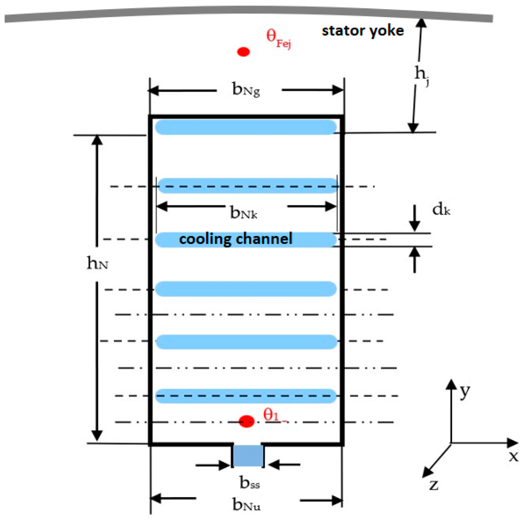
The cooling channels are simply produced during the impregnation process by removable inserts. This has the advantage that the cooling channels need no channel walls. As the cooling fluid is electrically insulating, no problems due to contact of fluid and wire are expected. The Litz wire winding requires rectangular slots, so that the teeth will be conical. Calculations by the authors of the heat transfer coefficients in the cooling channels with a polysiloxan cooling fluid showed that a hydraulic diameter of appr. 4 mm would be a good choice for the sizing of the cooling channels. Compared to reference [
1], the number of the cooling channels in the slot was increased from 2 to 6, while one cooling channel also works as an insulating phase separator in the center of the slot (
Figure 6). Due to the net slot width of 10.5 mm, a channel height of 2–3 mm is suitable.
As an air gap sleeve of non-conductive material is provided to separate the winding overhang spaces from the air gap, the slot opening also serves as a cooling channel. To allow an easy winding to process, the number of the cooling channels was adapted to the number of turns of the coils.
Due to the high voltage of the intermediate circuit, reinforced insulation of the slot liners and the phase insulation in the slot and in the winding overhang is necessary. Consequently, a slot filling factor of 50% only was calculated for the pure copper regions (without cooling channels).
The design process follows the standard routines for permanent magnet excited machines. Electric loading and flux density are kept constant to fulfill the requirements for power and voltage. A force density of appr. 60 kN/m2 was provided, which results in a little bit higher than the values of the usual permanent magnet machine designs. The design calculations were done by varying the current densities 15 A/mm2 ≤ S ≤ 45 A/mm2. They yield a medium depth design of the electrical machine with all necessary electrical and mechanical data from which here the dimensions and the weight were evaluated. During the design process, the short circuit current and the current at possible overload were reviewed to avoid demagnetization in the d-axis or edge demagnetization of the permanent magnets. To achieve this, the flux leakage of the slots was adjusted for each design.
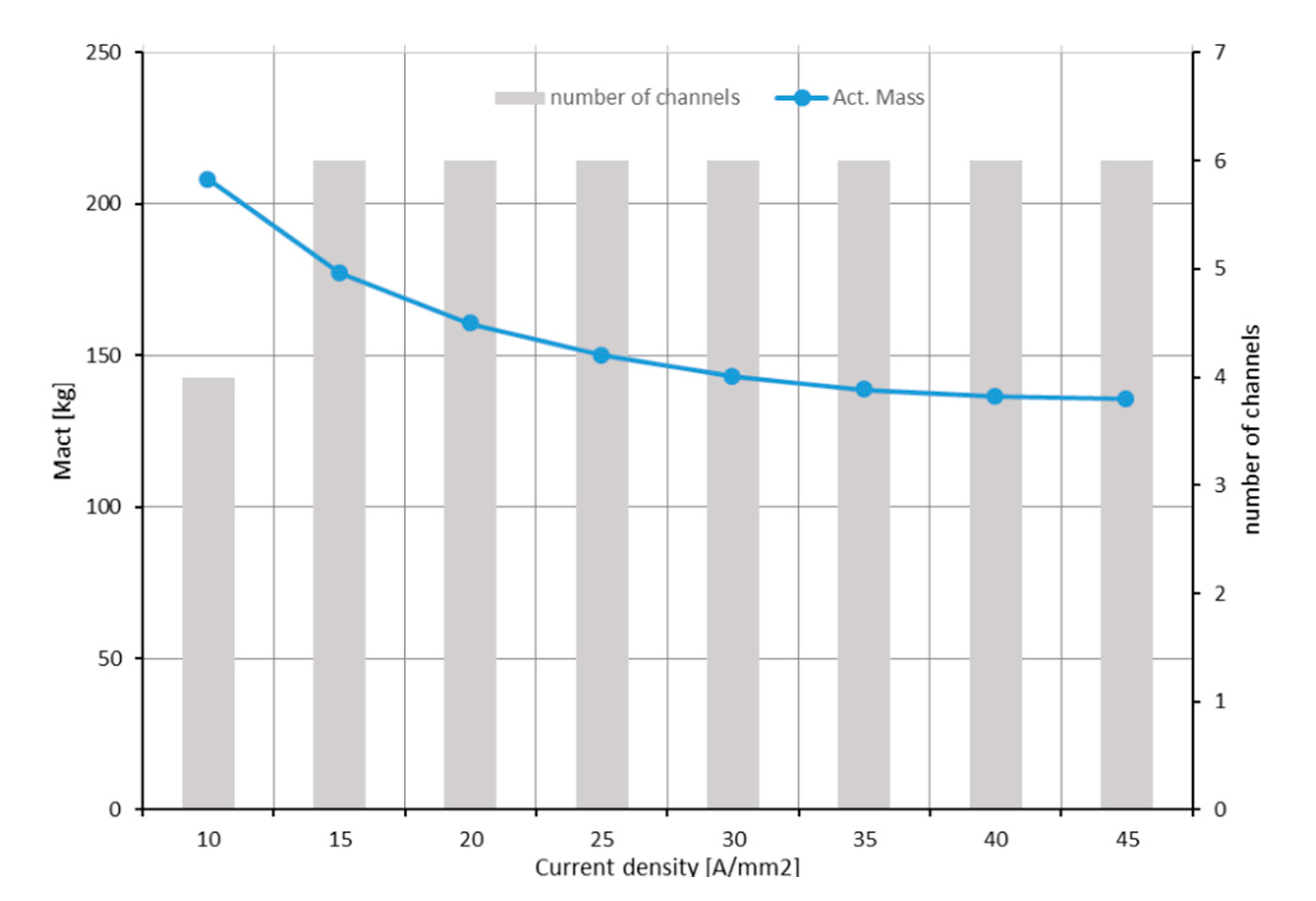
Figure 7 depicts the weight of the active parts and the number of cooling channels per slot as a function of the current density. While in all design calculations, current loading and flux density are kept constant with increasing current density, the copper weight is reduced, the slot height becomes smaller, and the weight of the teeth is reduced as well. As the weight of the yoke is only reduced because the teeth height becomes smaller, the weight function approaches a limit of appr. 95 kg at infinite current density, requiring an infinite efficient cooling system or at least superconductivity of the winding.
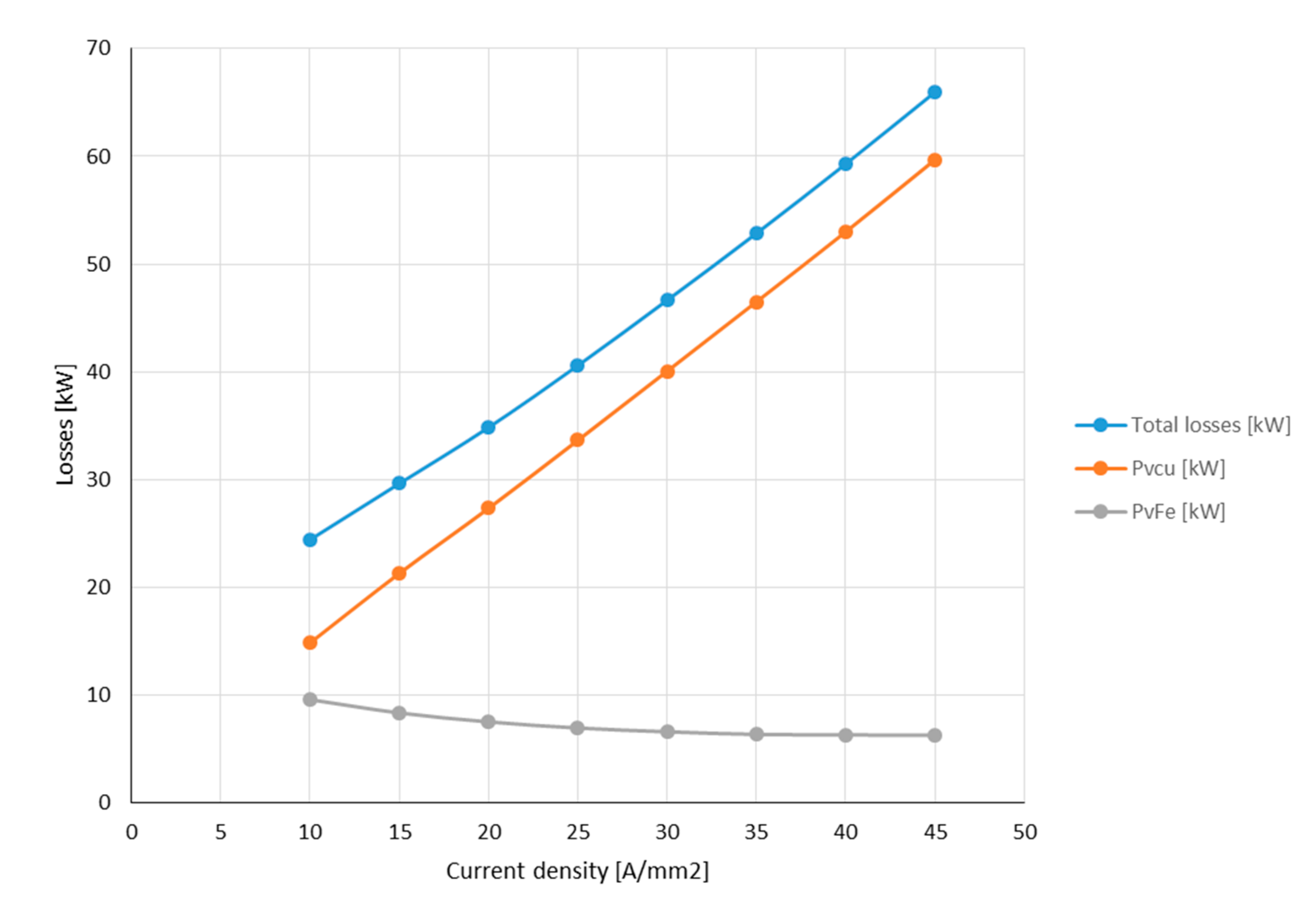
In this situation, there are no teeth at all, and on the inner surface of the yoke, a thin layer of current (a current sheet) remains. It is noteworthy that with higher current density, the degression of weight becomes smaller, while the copper losses increase linearly (
Figure 8). For example, the weight difference between 30 A/mm
2 and 40 A/mm
2 is approximately 5%, while the losses increase by 43%.
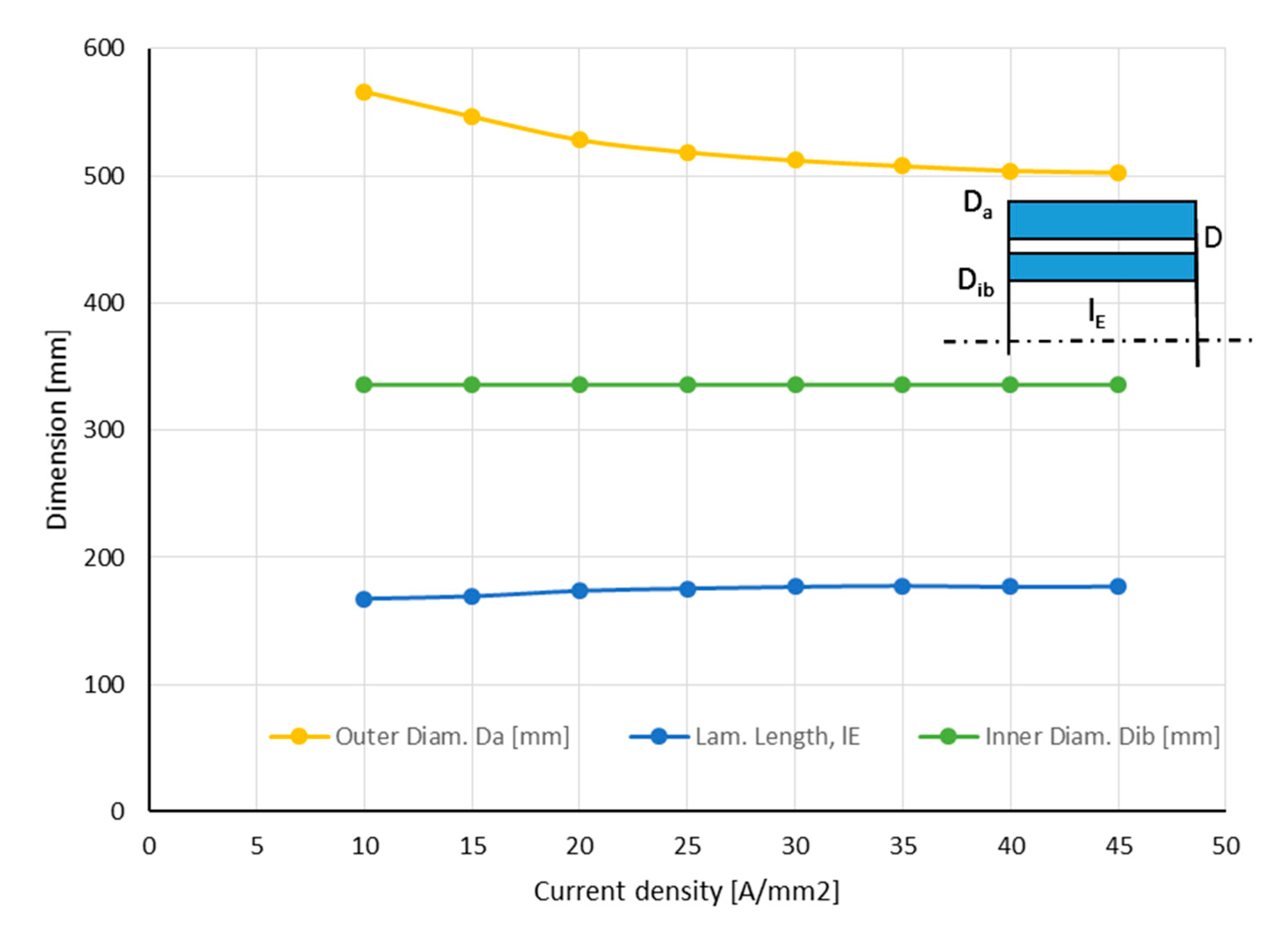
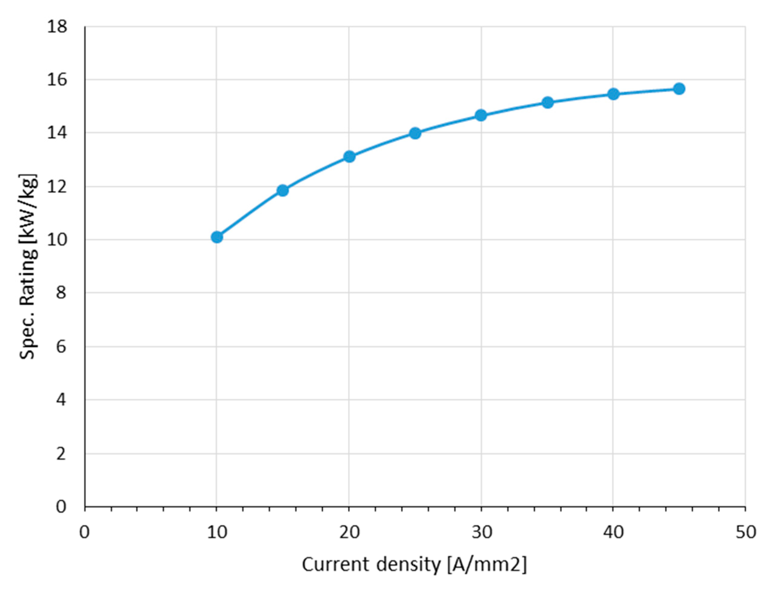
Reduction of the copper area reduces the copper volume by the same ratio as the current density is increased because we assume constant current. This gives a linear increase of the losses instead of the quadratic function usually expected with constant copper volume. The main dimensions of the lamination and the specific values of power density are given in
Figure 9 and
Figure 10.
Related to the active mass, the chosen design approach yields fairly good power by weight values. One has to keep in mind, that the drive weight, including power electronics, cooling system, and nacelle construction, will reduce these values significantly. A calculation of the housing weight depends very much on the design of the plane and is not the subject of this study.
5. Thermal Calculations
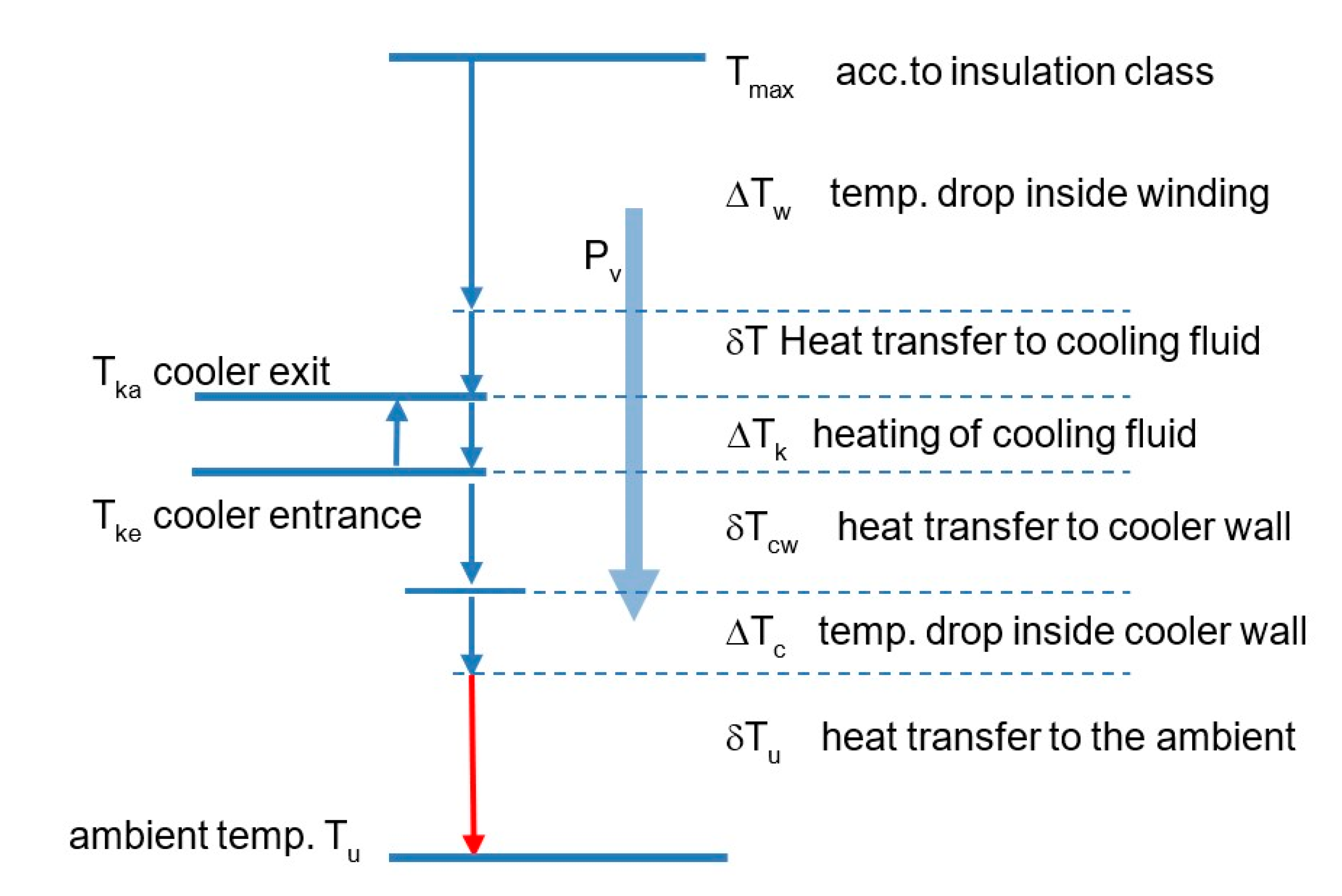
In general, the temperatures in the machine and inside the cooling system can vary only between two fixed boundaries: The maximum allowable temperature of the insulation (e.g., insulation class H with 180 °C, IEC 34, EN-DIN 60034) and the ambient temperature, here chosen to 40 °C. The difference between these boundaries splits up into the temperature drops inside the cooling system, according to
Figure 11.
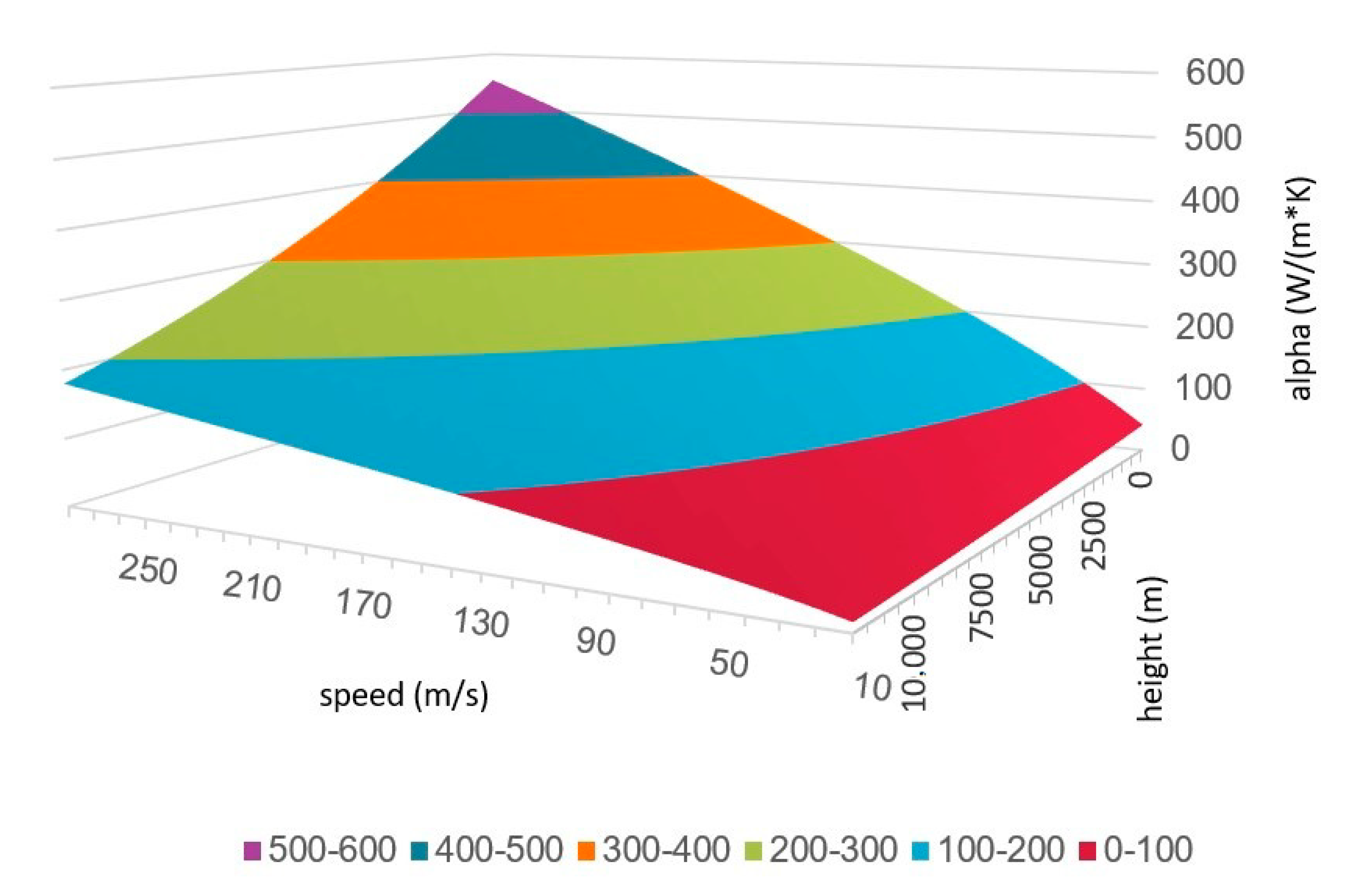
The preliminary calculation of the heat transfer coefficients from cooler to the ambiance (
Figure 12) shows comparatively small values, which increase with speed and decrease with height. For the anticipated worst-case scenario of a hot day take-off with 60 m/s (Ma = 0.2) this leads to large required cooler surfaces and corresponding weight, which is influenced by the losses of the machine and the value of δT
u.
Usually, the heating of the cooling fluid is small, due to its high thermal capacity. In steady-state conditions the cooling fluid is cooled down in the cooler by the same amount as it is heated in the machine, meaning the average temperature level of the cooling fluid is constant.
The temperature drop inside the cooler wall is negligibly small if a cooler structure with hollow fins or a thin-walled surface cooler is used as proposed in chapter 7.
The critical figure in this calculation is the temperature difference δTu available for the heat transfer to the ambiance. This determines the size and weight of the cooler. If the other temperature drops are too high, there remains only a small temperature gap for the heat transfer to the ambient resulting in a huge cooler surface and heavy cooler weight.
Temperature Drop within the Winding
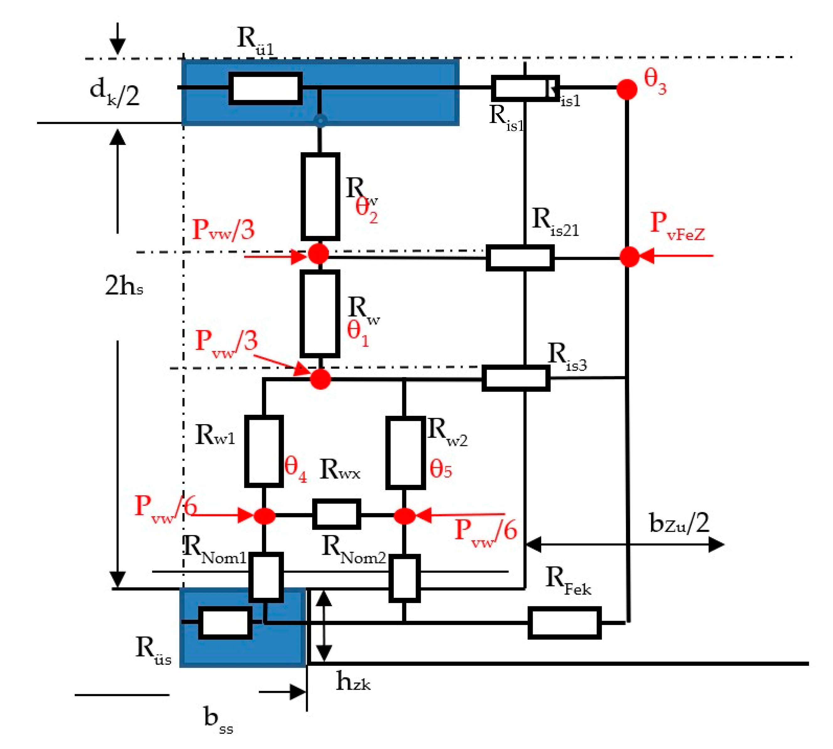
As the analytical loss calculation of the machine accounts only for classical copper losses, for all thermal calculations, the losses in the machine were increased by a flat amount of additional losses of an estimated 5 kW to have a more realistic scenario. The calculation of the temperature distribution in the winding was done with numerical methods and counter checked with an analytical thermal equivalent network (TEN). As the cooling channels can be seen as isothermal layers, the slot sections between the channels are decoupled as a first approximation. The critical section is the one at the slot opening. For the temperature check, it is sufficient to model this section, as depicted in
Figure 13, for a half section and a half tooth.
The thermal calculations are deliberately made for a steady-state situation. The thermal equivalent network can be expanded by the thermal capacities of the considered elements what in the steady-state condition is not necessary. The thermal behavior of the normal conducting system is an approximation of a P-T1 characteristic with a large time constant, which is easily controlled by the volume flow of the coolant. Therefore, there appears no risk of thermal instability.
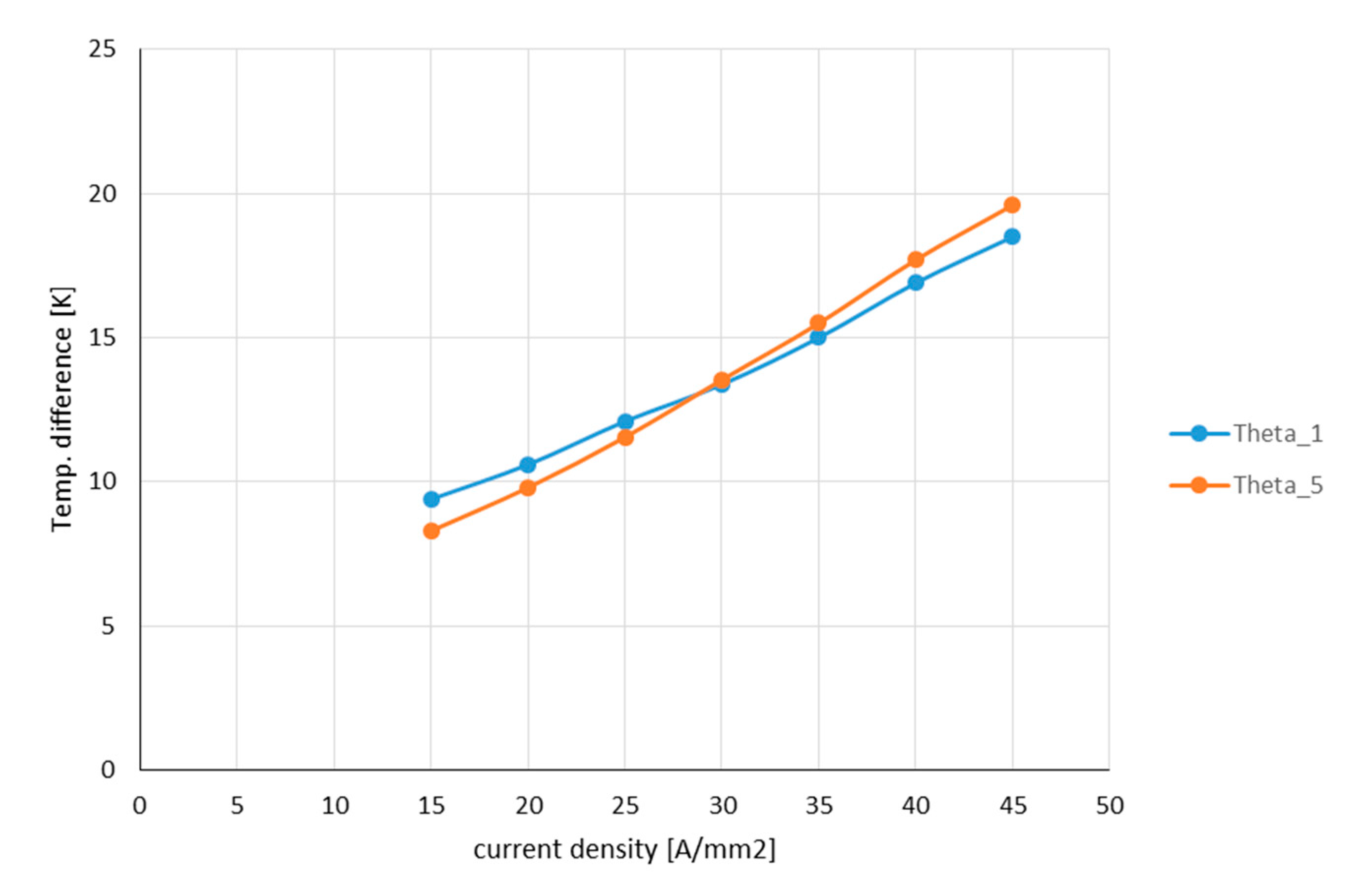
Figure 14 shows the temperature rise at the hot spots θ
1, θ
5 of the TEN. The temperature rise of θ
5 increases a little bit faster over the current density. The reason is an increase of the influence of the losses transferred over the tooth head to the slot opening channel.
For the critical region at the slot opening, the heat transfer coefficients of the cooling channel and slot opening will be different, due to their different dimensions and flow velocities. Therefore, both channels were treated separately. As the heat transfer coefficients in both channels are different, also different equivalent resistances R
ü1, R
üs in the analytical network occur. Consequently, the calculated temperature drops of
Figure 14 are related to the average cooling fluid temperature.
To consider the dependency of the thermal material parameters of the cooling fluid as density, viscosity, thermal conductivity, and heat capacity [
2] influencing mainly the Prandtl number Pr, these parameters were adapted iteratively to the calculated temperatures [
16,
17].
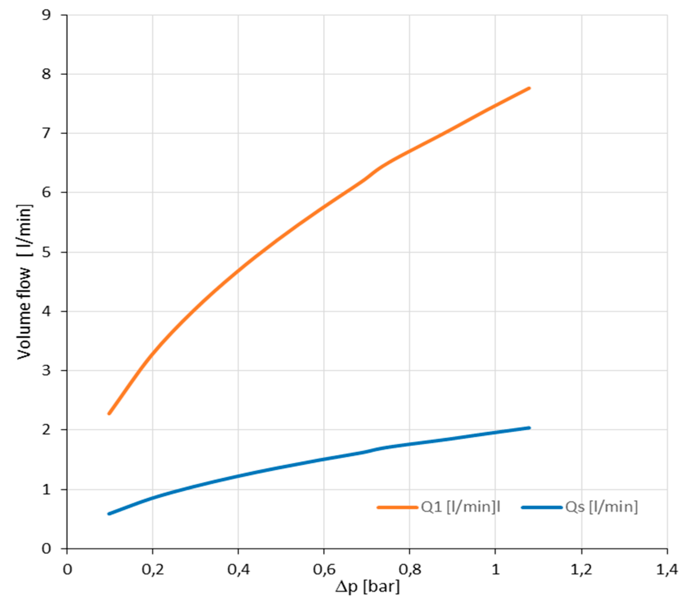
In this study, the pressure difference Δp over the lamination length was limited to a fixed value of 0.245 bar to keep the power consumption of the pump and the dimensions of the pipes within reasonable limits (
Figure 15). Further pressure drops occur in the winding overhang spaces, the piping, and the cooler, which all must be covered by the pressure developed by the pump.
The flow velocities were calculated from the pressure difference Δp over the parallel channels in the slots according to standard literature [
16]. The velocity inside a channel as a function of the prescribed pressure is
With ρw density of cooling fluid ζe, ζk, ζük flow resistance coefficients for the transition into the channel, channel friction, transition from the channel into free space with Ak, ANw channel area, and the area of the free flow inside the winding overhang space.
The heat transfer coefficients inside the channels were calculated with the flow data from the pressure calculation as Reynolds number Rey and Prandtl number Pr according to References [
16,
17]. Nusselts number for heat transfer inside a channel or tube is:
The correction factor k
1 refers to the different temperatures and Prandtl numbers inside the fluid and at the channel wall. In most cases, it is very close to 1. The coefficient of heat transfer is then
With λw thermal conductivity of the cooling fluid and dh hydraulic diameter of the channel.
The temperature drop of heat transfer follows
With Pvk the transferred power, πLkdh the heat transferring surface.
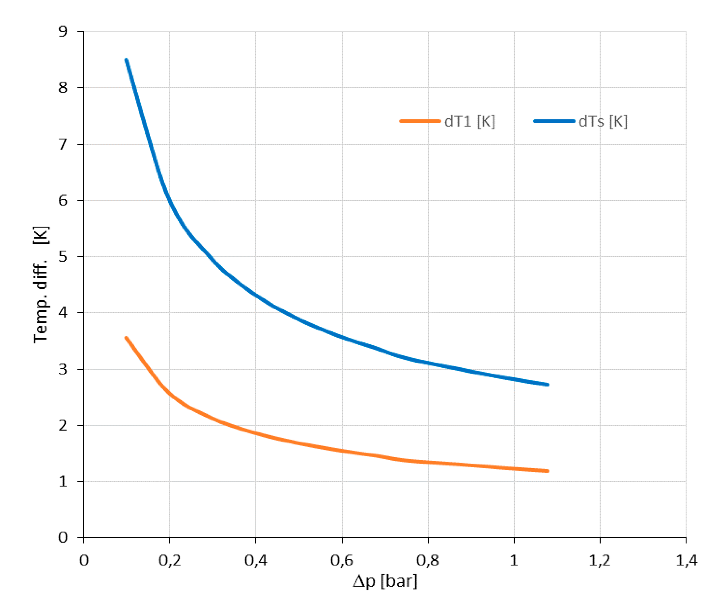
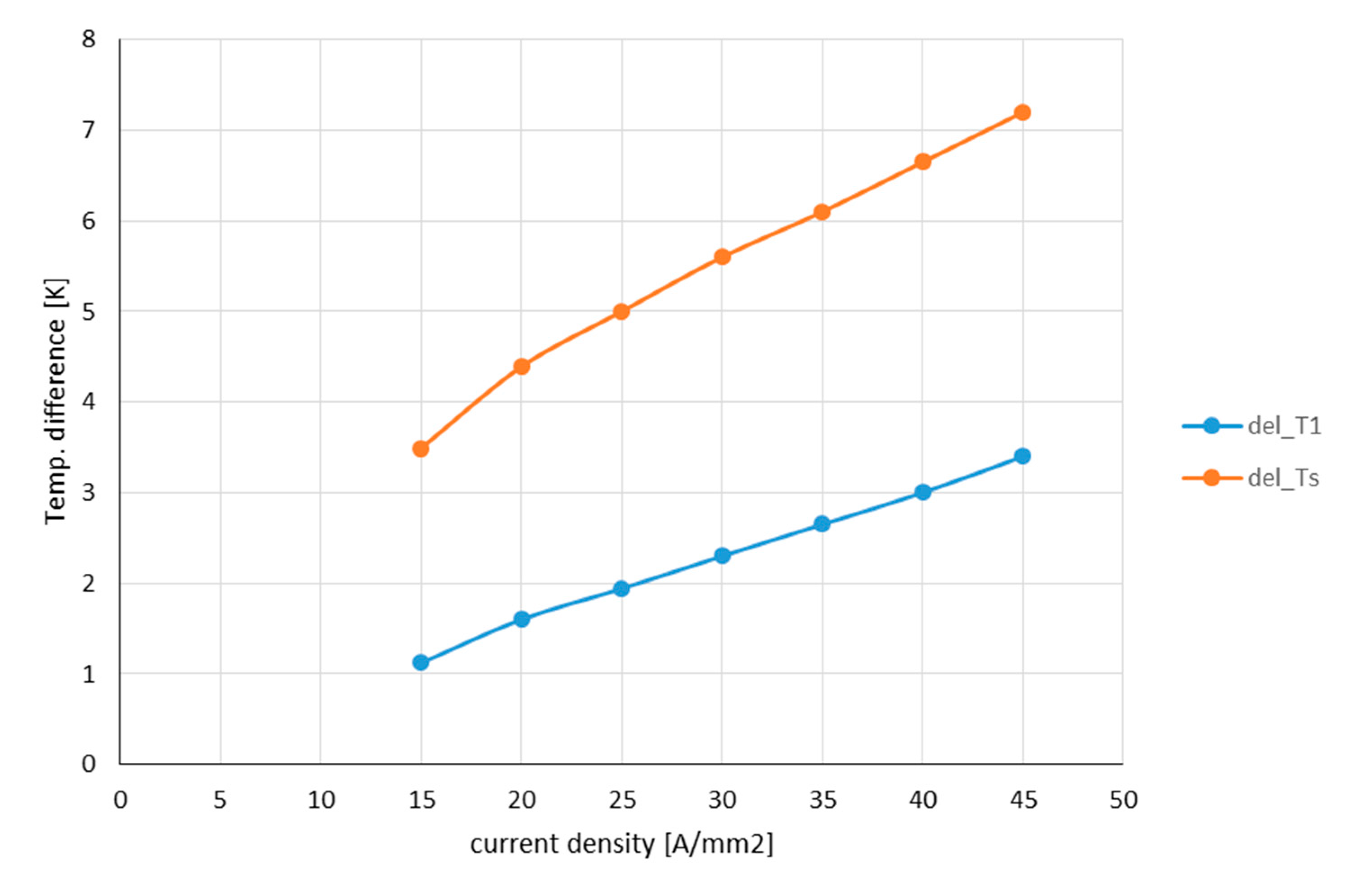
Figure 16 and
Figure 17 show typical functions of temperatures δT
w over the pressure difference of the cooling channels and the current density.
Due to the multichannel configuration, the temperatures of the heat transfer are acceptable even at higher current densities, although a moderate pressure drop has been chosen. From these values and the corresponding heat flows, thermal resistances (R
ü1, R
üs) were derived and iteratively introduced into the TEN of
Figure 13.
6. Inverter
The inverter is handled in this study as a black box. It is advantageous to provide a separate cooling circuit for the inverter, because pressure drops and required coolant flow are different to those of the machine, and a different temperature level is required for the effective cooling of the power electronic devices. An electrically isolating cooling fluid as Syltherm [
2] will contribute to a weight-saving construction. As the rated power is constant and independent from the current densities in the machine, the inverter contributes a constant weight to the system balance. Conventional water-cooling automotive inverters show a rating of 0.07 kg/kVA, but the development of high power density inverters is in progress, so no fixed figures can be given. The weight of the inverter depends in principle on the apparent power P
A and is dominated by the electronic power switches, the capacitor in the intermediate circuit, and the cooling system. The choice of the components depends on the blocking voltage and the maximum current. So the apparent power of a 3 phase inverter with output Voltage amplitude
and current amplitude
is usually used as an appropriate measure for the rating of the inverter.
Due to the different flux leakage in the current density-dependent machine design, the power factor varies between 0.771–0.824 with increasing current density, while the efficiency has an adverse tendency. Consequently, the apparent power variation is not significant. With a conservative estimation of a specific ratio of 0.03–0.04 kg/kVA the inverter will add appr. 100 kg weight to the system that represents the actual state of the art sufficiently. Even more optimistic figures in prototype applications down to 0.02 kg/kW are given in references [
18,
19], so the actual estimation is on the safe side.
7. Cooling Equipment
7.1. Surface Cooler
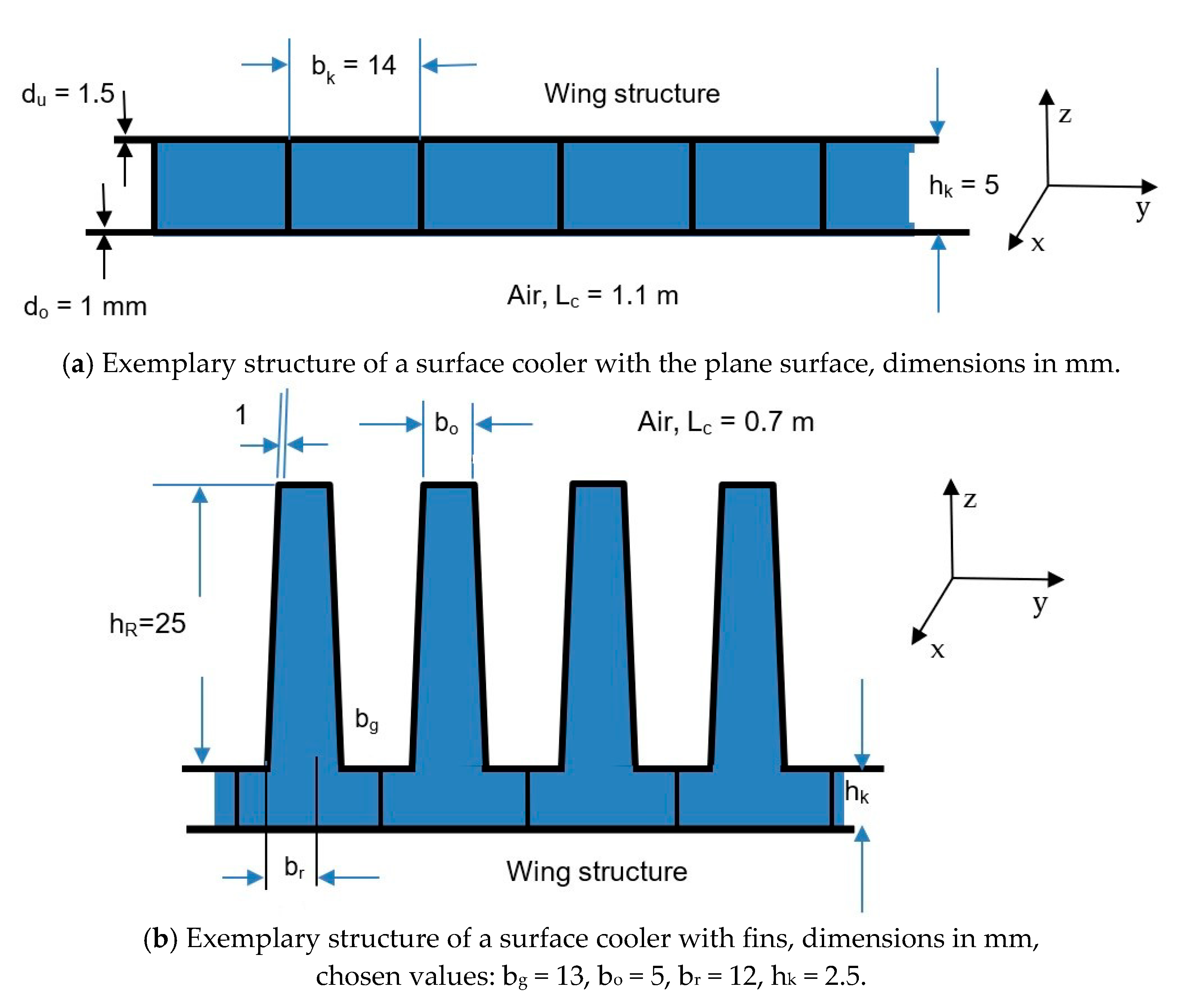
As a cooler surface heat exchanger is chosen. It has the advantage of minimal drag, and it is a passive device with no puller fan, which is energy consuming, adds additional weight, and has a certain failure probability. The construction can deploy a plane surface or a fin structure, as in
Figure 18a,b, both preferably integrated on the bottom side of the wing.
The cooling fluid passes through the channels in x-direction is indicated in
Figure 18a,b. The given dimensions also serve for the weight calculation. The outside air also flows in axial (x) direction over the surface of the cooler. For the mass balance, only the additional weight of the cooler is of interest what implies that only the additional material as upper folded sheet and separator sheets, as well as fluid filling count for the mass balance, and the lower sheet is part of the wing structure.
The heat exchanger with fins can also be integrated into the nacelle housing with the advantage of higher turbulence, and therefore, a smaller allowable surface. But for easier comparison, it was assumed that both coolers are an integral part of the wing.
In the cooler, two relevant temperature drops are dominant: Heat transfer from cooling fluid to the cooler outside wall and heat transfer from the cooler outside surface to the ambient air. A recursive calculation is necessary to adjust both to the chosen conditions. The temperature drop in the cooler walls is in the region of mK and neglectable compared with the other temperature differences. The calculations for the sizing of the cooler surface follows the usual design process with the average Nusselt number and average heat transfer coefficient. Here the results given in Reference [
20] were evaluated. While the finned cooler induces turbulent flow already at the upstream end, with a plane cooler first, a laminar flow develops with the transition to a turbulent flow along the cooler length x.
For the data assumed here, the transition to turbulence starts approximately at x = 110 mm, and full turbulent flow is achieved after x = 230 mm. As the Nusselt number and the heat transfer coefficients vary now along the cooler surface, average values were calculated by integration along the cooler length x. The average Nusselt number is given then in Reference [
18]:
Pr: Prandtl number
ReyL: Reynolds number for the full length Lc
Reyl: Reynolds number at the beginning of the transition
Reyu: Reynolds number were turbulent flow is achieved
The turbulent section of the cooler length (First term in Equation (6)) gives the highest contribution to the heat transfer, but the heat transfer coefficient drops also with the length of the turbulent region. That is why the calculation of the cooler weight shows a flat minimum at Lc = 0.7 m for the cooler with fins and Lc = 1.1 m for the plane cooler.
As the inside of the cooler is divided into a plurality of separate channels guiding the coolant flow through the cooler, the heat transfer can be calculated for each channel with the hydraulic diameter d
hc. It is assumed that the coolant flow in all channels is the same as what is achieved by little restrictions at the entrance of the channels. The pressure differences over the cooler channels and within the flow distribution devices were calculated using [
16,
17]. For a volume flow inside a cooling channel Equation (6) applies again.
The calculations were done for a constant volume flow of 1630 l/min of coolant, which requires different pressures for each cooler type. But adjusting of the pressure by a centrifugal pump is easy, and the pumping power is small compared with the losses. Nevertheless, the optimization of the volume flow depending on the thermal situation in the machine is a further component for the optimization of the system.
The material properties defining the Prandtl numbers as viscosity η
a, thermal capacity cp
a, and thermal conductivity λ
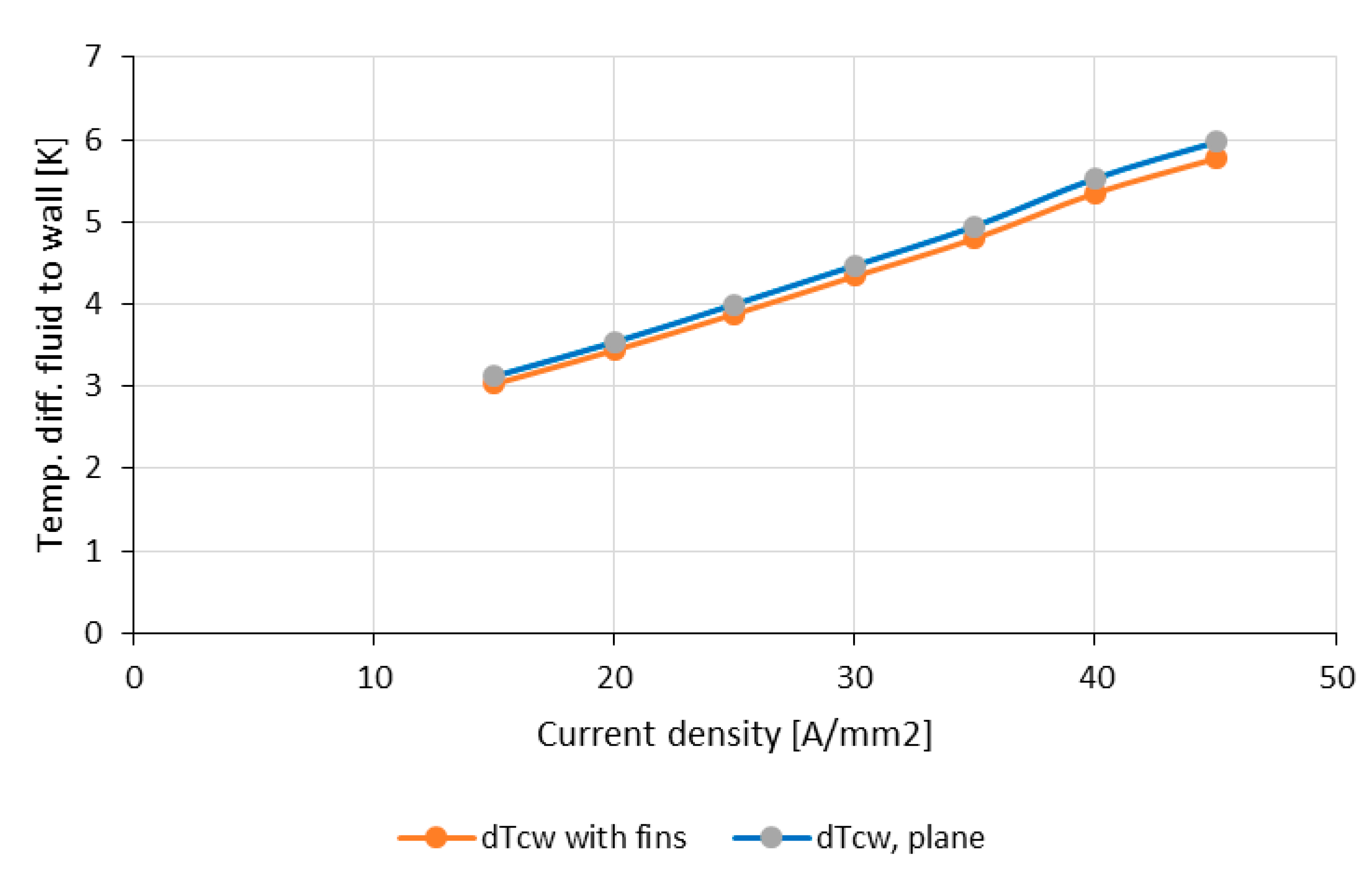
a of the ambient air were adjusted to the given temperature. From the heat transfer coefficient, the thermal power and the available temperature difference δT
u to the ambiance (compare
Figure 11) follows the size of the cooler and the number of required channels. With these values, the temperature drop from cooling fluid to the cooler wall can be recalculated, giving a new value for δT
u, and the calculation of the cooler size is restarted (
Figure 19). Usually, convergence is achieved after one or two recursive cycles.
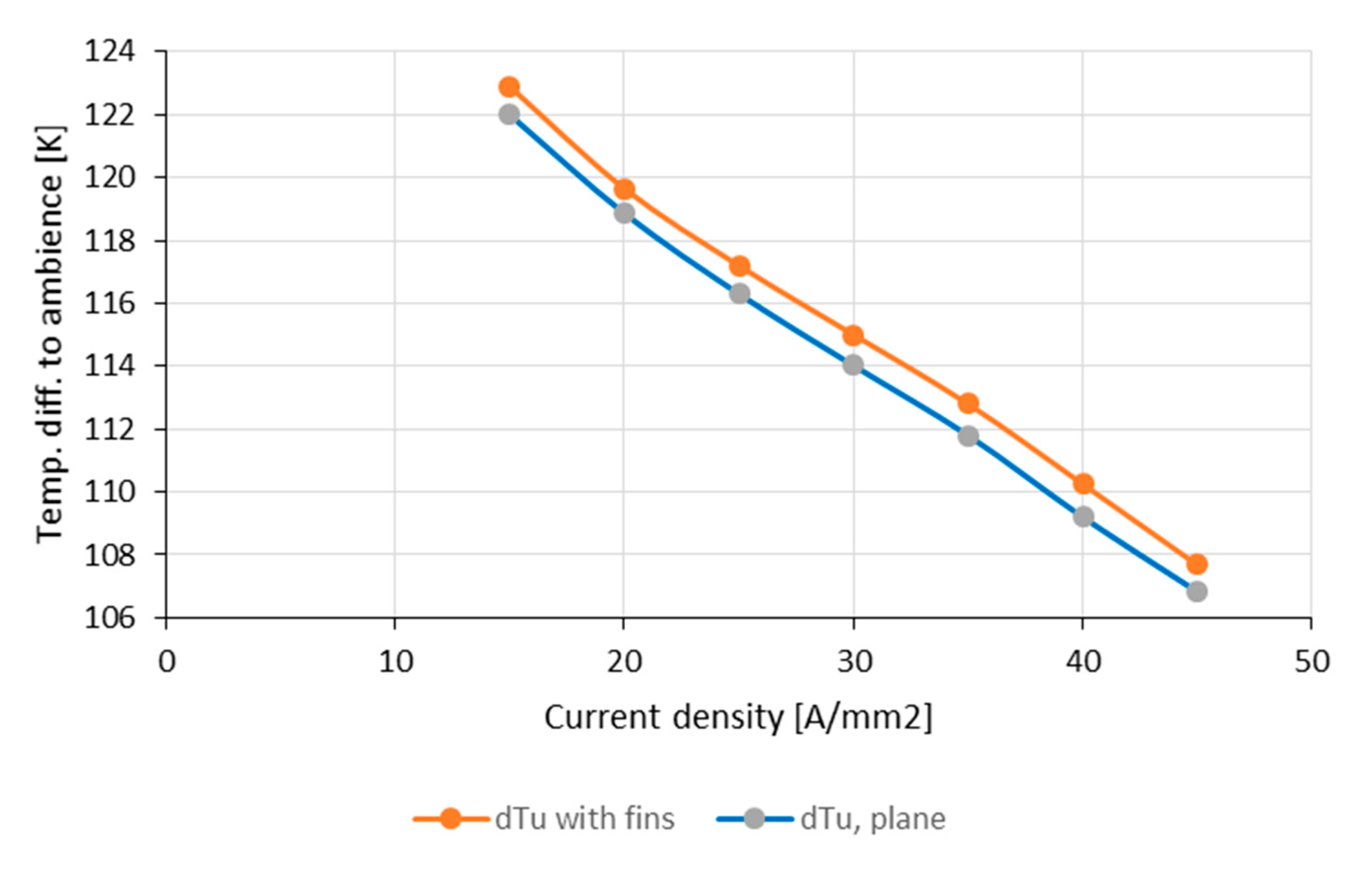
The small difference between the two temperatures comes from the different heat transfer coefficients, due to the smaller velocities of the fluid in the plane cooler. The temperature difference from cooler to the ambient air is nearly the same, as shown in
Figure 20.
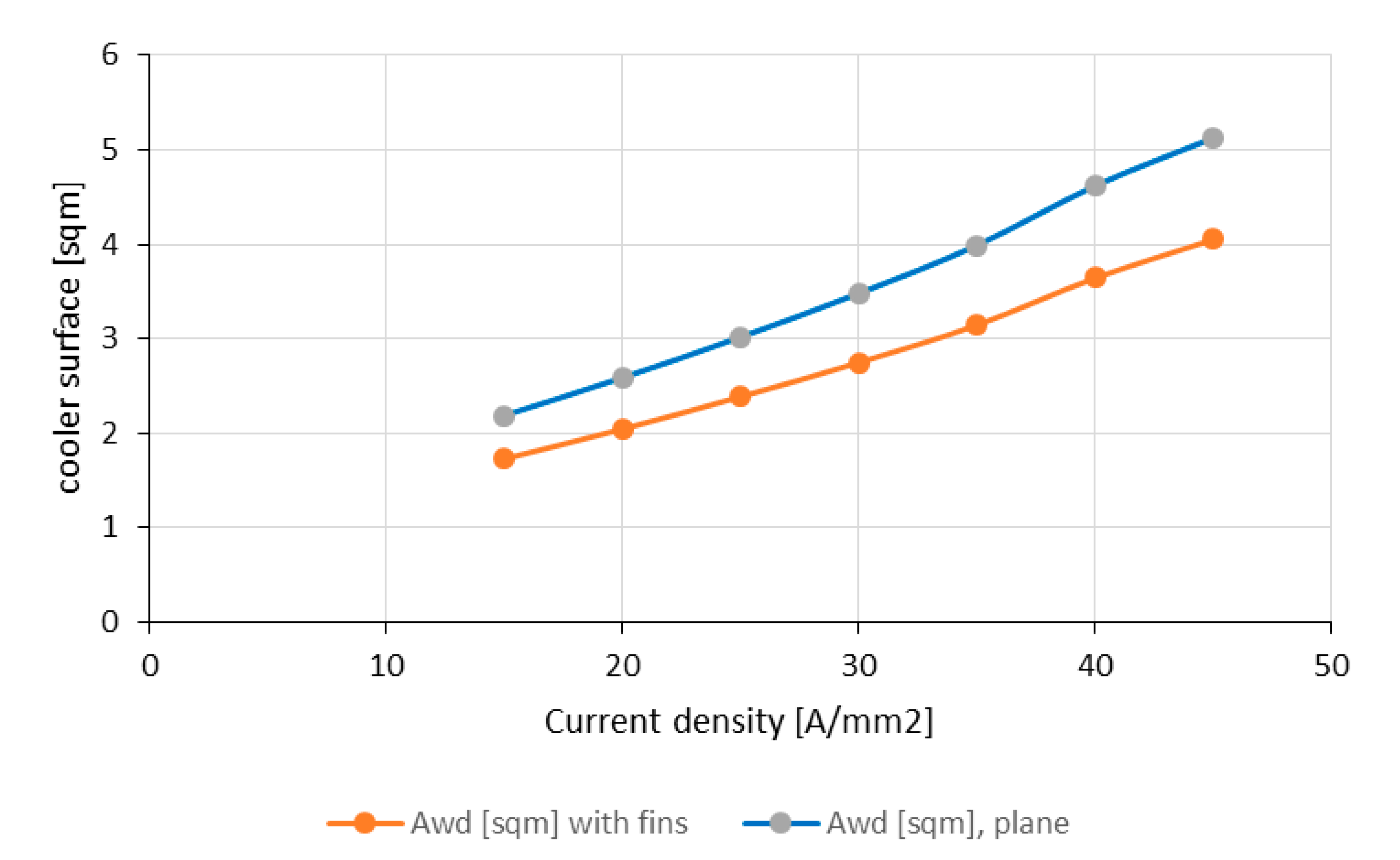
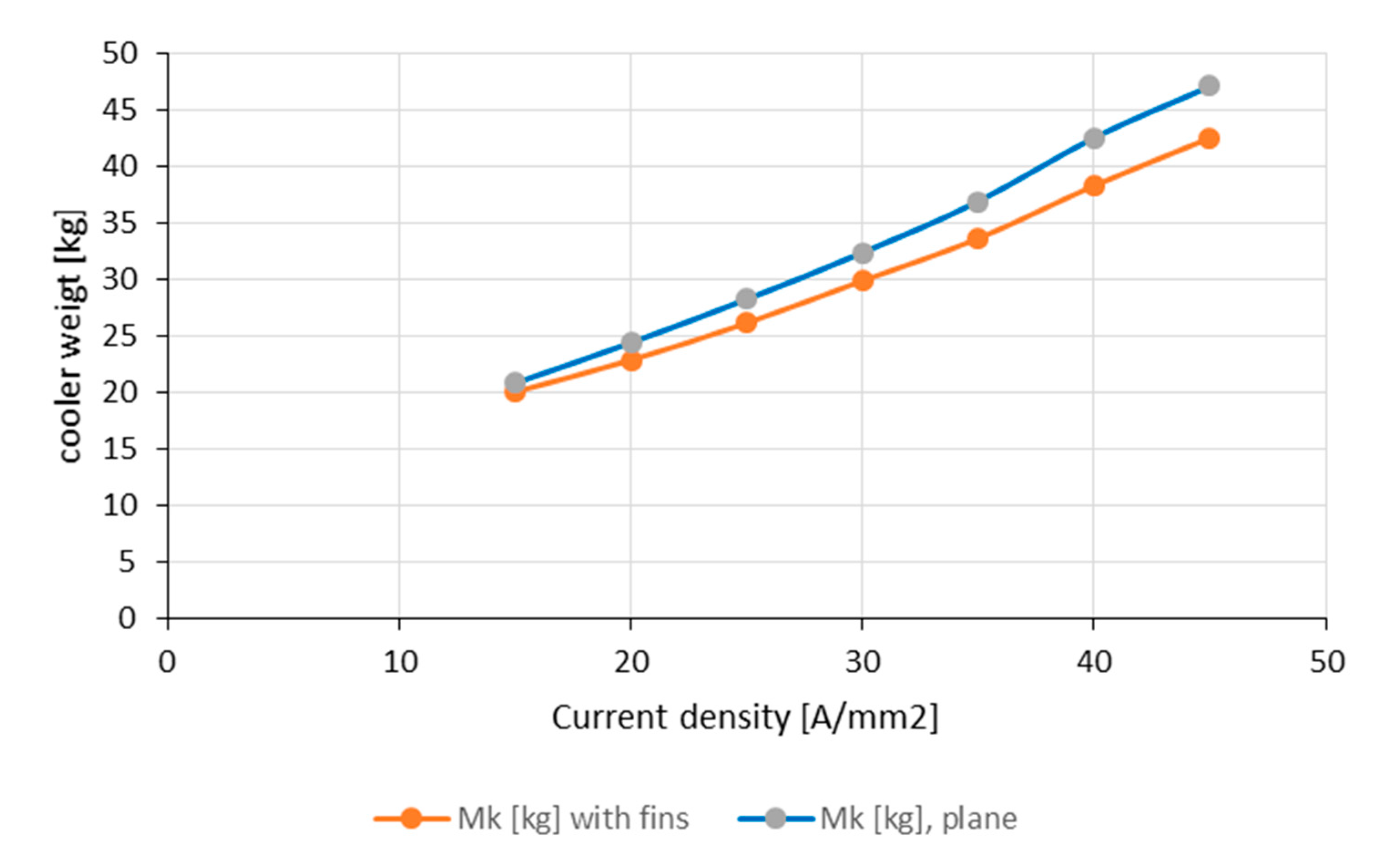
Consequently, both coolers should have the same active surface (
Figure 21). But as the heat transfer coefficients differ, the surface of the plane cooler is larger. This results in a larger weight of the plane cooler (
Figure 22), but the difference between both types is surprisingly not very impressive. Therefore, a plane and easy to manufacture cooler may be a viable alternative.
For the estimation of feasibility, the width of the cooler is an important figure. As the length of the cooler was fixed to 0.7 m and 1.1 m, respectively, the plane cooler requires a considerable that which follows directly from the surface (
Figure 21). While a width of 3 m at 30 A/mm
2 may be a feasible figure for a plane of the anticipated size, the feasibility of the higher values is questionable.
In contrast to this, a cooler with fins placed in the more turbulent propulsor airstream around the nacelle may have a higher depth than 0.7 m without the problems of reduced heat transfer as mentioned before. Moreover, the weight of the piping will be reduced because of the smaller distances.
7.2. Pump and Piping
A centrifugal pump was chosen to cover the pressure difference in the cooling system. This pressure difference depends on the pressure drops in the machine, the cooler, and the pipes with an unknown number of bends. With a pressure drop in the machine of 245 mbar, in the cooler of appr. 30–60 mbar, the overall pressure capacity of the pump was chosen to 800–1000 mbar to cover all eventualities. That yields a maximal power rating of 2–3 kW. Looking into the data sheets of suppliers of industrial centrifugal pumps [
21] shows that one pump can cover a wide range of volume flow and pressure differences by choice of appropriate feeding frequency and speed. That is why one pump can cover the whole range of pressure and volume flow discussed here and adds only a constant value to the weight balance. According to catalog data, the required width of the connecting pipes is DN = 80 mm on the pressure side and DN = 100 mm on the suction side.
An appropriate pump of these ratings weighs appr. 80–90 kg in industrial construction with cast iron 16 bar housing and standard IEC motor. Adoption to the requirements of aircraft operation with aluminum housing and impeller wheel and with a fluid-cooled motor will reduce the weight to appr. 20–30 kg.
The piping is the most unknown component in the system because the spatial distance between the electric machine and cooler depends on the construction of the whole aircraft and is not known yet. To include the contribution of pipes and flanges to the estimated weight balance, a piping of 10 m overall length was estimated. With aluminum pipes of 2.5 mm wall thickness, the weight balance is given in
Table 3:
This rough calculation shows the weight of the pipes is not neglectable and in the range of the pump weight. At this stage of the design considerations, a constant value for the piping independent of the losses is added to the weight balance.
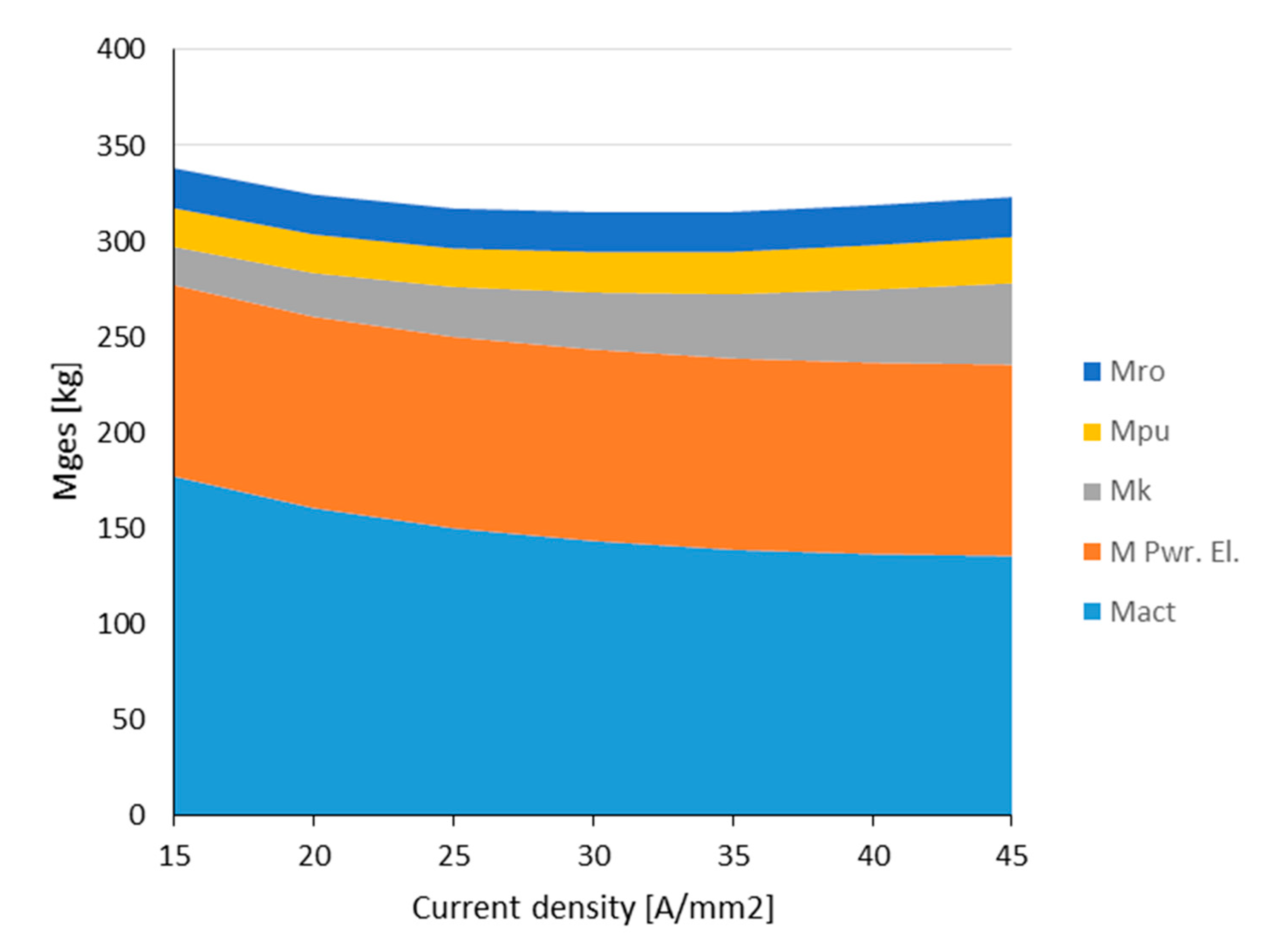
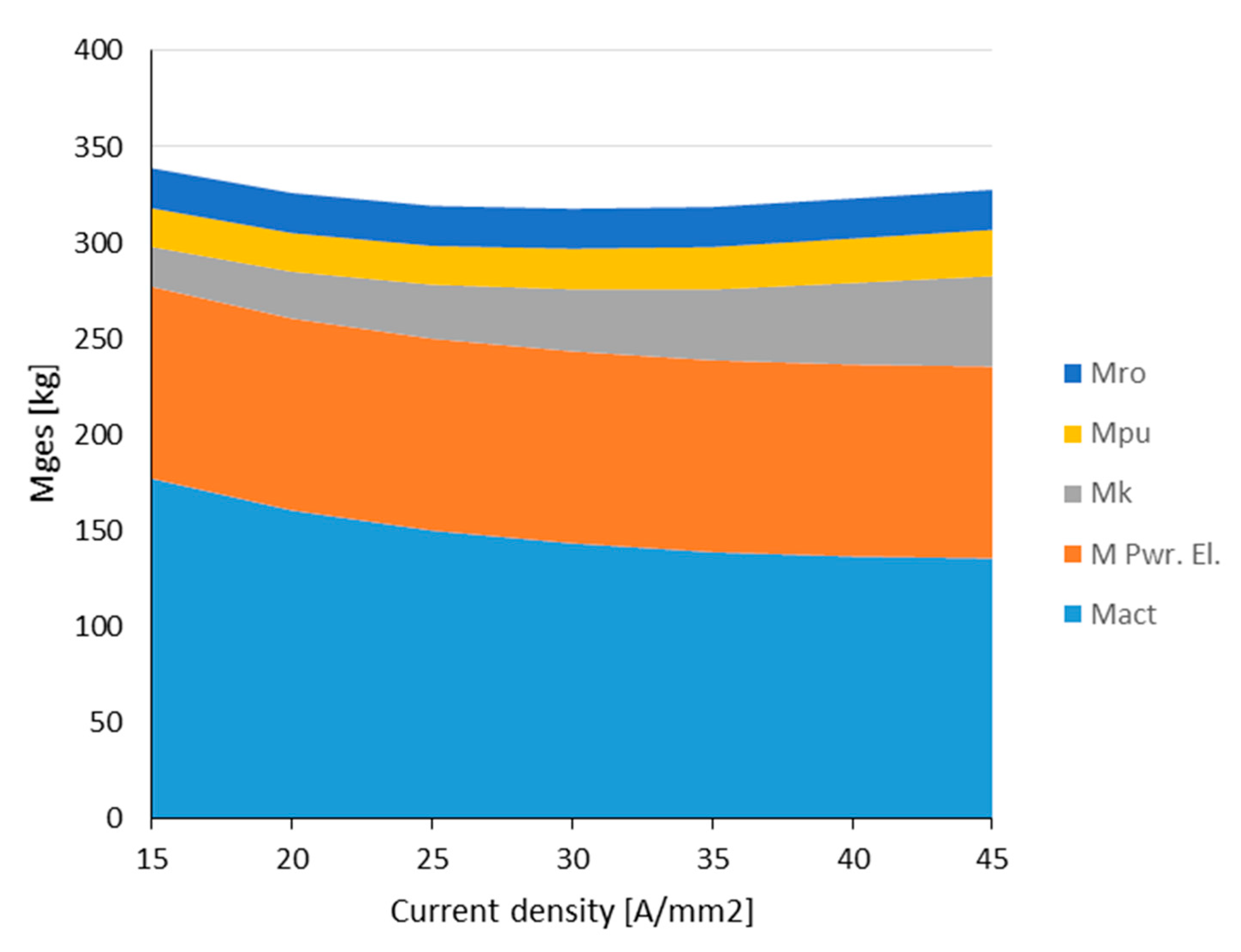
8. Weight Balance
The weight balance is established without any construction elements for nacelle or gears. It contains the weights of machine (M
act), power electronics (M
Pwr.El), cooler (M
k), pump, and piping (M
pu, M
ro).
Figure 23 shows it for a cooler with fins, and
Figure 24 refers to a plane surface cooler.
Both figures show a flat minimum between 30 and 35 A/mm2 current density. The system mass at these values is appr. 315–317.5 kg leading to a specific system weight of 6.6–6.7 kW/kg. While the weight of power electronics, pump, and piping are estimated as constant values in this calculation, the main influences come from the active weight of the machine and weight of the cooler.
9. Discussion and Conclusions
Although a lot of assumptions were necessary to conduct this exemplary study, it revealed some unambiguous conclusions and tendencies which are helpful for more specific design calculations.
Looking at the current density and the losses as important design parameters, the main influences on the weight balance of the drive result from the machine and the heat exchanger design. In the normal conducting machine with copper winding, the weight decreases with the current density following a hyperbolic function, while the losses increase nearly linear. Consequently, the gain of weight at high current densities becomes smaller, while the losses increase significantly. This strongly interlinked relationship has been systematically elaborated in this study.
To remove the losses with a lightweight cooling system, the key figure is the temperature difference between cooler surface and ambiance δTu, which reaches here a level of appr. 100–120 K. To keep this as high as possible, the other temperature drops in the cooling system should be kept at corresponding small values. This can be achieved by a multichannel direct slot cooling system. The machine weight minimum can be reached by designing and implementing a current density defined between 30 A/mm2 and 35 A/mm2. As was learned from separate calculations with only two cooling channels, this minimum will shift to current density values around 20 A/mm2, while the cooler size and weight increase exponentially.
The question of implementing a cooler with fins or a plane one is more a question of costs than of weight because the difference between both is small compared with the overall weight of the drive.
Of interest may be a reduction of the maximal temperature in the slot (class H implemented and machine calculation appropriate for class F, as often demanded in practice), to increase the lifetime of the insulation and to provide a safer overload capability. With the proposed design approach this has been calculated exemplarily for 30 A/mm2. It will reduce the overall losses by 6.7% and the temperature difference to the ambiance δTu to 90 °C. The cooler surface had to be increased by 22%, and the cooler weight increases only by 14%.
In addition to the considerations on the electric machine presented here, the power electronics and auxiliary units play a further essential role in optimizing the weight ratios in the overall system. The power electronics design depends on the apparent power rating, the voltage in the intermediate circuit, and the switching frequency, which adds a constant figure in the weight balance. The optimization of the weight of power electronic systems is a task for future research [
22]. These systems have to include a separate cooling system as well. Moreover, piping and pumps contribute a constant figure to the weight balance, but the amount of volume flow influences the temperature drops in the machine and the temperature difference to the ambiance. The pressure assumptions in this study were more on the cautious side. An optimization approach could be to adopt the volume flow and the power rating of the pump to the tolerable system pressure.
The study elaborated on the dependencies described by using an explicit design example. The approaches were presented in a generalized way, so that a transferability to machines with a similar stator design will be possible. For machine topologies with a different mode of operation or a substantially different performance class, the assumptions regarding thermal behavior are generally valid, whereby for new performance characteristics, corresponding model laws must be applied.
Author Contributions
Conceptualization, W.-R.C., M.H., J.H.; software, W.-R.C., J.H.; validation, W.-R.C., J.H.; investigation, J.H.; resources, M.H.; data curation, W.-R.C., J.H.; writing—original draft preparation, W.-R.C.; writing—review and editing, M.H.; visualization, W.-R.C., J.H.; supervision, M.H.; project administration, M.H.; funding acquisition, M.H. All authors have read and agreed to the published version of the manuscript.
Funding
We would like to acknowledge the funding by the Deutsche Forschungsgemeinschaft (DFG, German Research Foundation) under Germany´s Excellence Strategy—EXC 2163/1-Sustainable and Energy Efficient Aviation—Project-ID 390881007.
Acknowledgments
Furthermore, we acknowledge support by the Open Access Publication Funds of the Technische Universität Braunschweig.
Conflicts of Interest
The authors declare no conflict of interest.
References
- Canders, W.-R.; Hoffmann, J.; Henke, M. Cooling Technologies for High Power Density Electrical Machines for Aviation Applications. Energies 2019, 12, 4579. [Google Scholar] [CrossRef]
- Dow Corning Corporation. Syltherm HF: Heat Transfer Fluid, Product Technical Data; Dow Corning Corporation: Midland, MI, USA, 2019. [Google Scholar]
- Kellermann, H.; Habermann, A.L.; Hornung, M. Assessment of Aircraft Surface Heat Exchanger Potential. Aerospace 2020, 7, 1. [Google Scholar] [CrossRef]
- Lindh, P.; Petrov, I.; Pyrhönen, J.; Niemelä, M.; Immonen, P.; Scherman, E. Direct liquid cooling method verified with a permanent magnet traction motor in a bus. In Proceedings of the (ICEM) XIII International Conference on Electrical Machines, Alexandroupoli, Greece, 3–6 September 2018. [Google Scholar]
- Schiefer, M.; Doppelbauer, M. Indirect slot cooling for high power density machines with concentrated winding. In Proceedings of the IEMDC-IEEE International Electric Machines & Drives Conference, Coeur d’Alene, ID, USA, 10–13 May 2015. [Google Scholar]
- Langheck, A.; Reuter, S.; Saburow, O.; Maertens, R.; Wittemann, F.; Berg, L.; Doppelbauer, M. Numerical and experimental investigation of flow phenomena in rotating step-holes for direct-spray-cooled electric motors. In Proceedings of the EDPC—8th International Electric Drives Production Conference, Schweinfurt, Germany, 4–5 December 2018. [Google Scholar]
- McCluskey, F.P.; Sadoon, Y.; Yao, Z.; Camacho, A. Cooling for electric aircraft motors. In Proceedings of the ITherm—18th IEEE Intersociety Conference on Thermal and Thermomechanical Phenomena in Electronic Systems, Las Vegas, NV, USA, 28–31 May 2019. [Google Scholar]
- Maalouf, S.; Isikveren, A.; Dumoulin, P.; Tauveron, N.; Cotereau, N. High Temperature Heat Pump for Aircraft Engine Oil Cooling. Available online: https://www.researchgate.net/profile/Samer_Maalouf/publication/329191675_High_Temperature_Heat_Pump_for_Aircraft_Engne_Oil_Cooling/links/5bfc103a458515b41d0f7034/High-Temperature-Heat-Pump-for-Aircraft-Engine-Oil-Cooling (accessed on 21 September 2020).
- Deisenroth, D.C.; Ohadi, M. Thermal Management of High-Power Density Electric Motors for Electrification of Aviation and Beyond. Energies 2019, 12, 3594. [Google Scholar] [CrossRef]
- Christie, R.J.; Dubois, A.; Derlaga, J.M. Cooling of Electric Motors Used for Propulsion On SCEPTOR. Available online: https://ntrs.nasa.gov/archive/nasa/casi.ntrs.nasa.gov/20170004363.pdf (accessed on 21 September 2020).
- Davin, T.; Pelle, J.; Harmand, S.; Yu, R. Experimental Study of Oil Cooling Systems for Electric Motors. Available online: https://www.sciencedirect.com/science/article/abs/pii/S1359431114009314 (accessed on 21 September 2020).
- Woodworth, A.A.; Smith, A.; Sixel, W.; Edwards, R.; Jansen, R.; McCormick, S.; Robbie, M.; Szpak, G.; Naghipour, P.; Euy-Sik, S. Thermal Analysis of Pottet Litz Wire for High-Power Density Aerospace Electric Machines. In Proceedings of the AIAA Propulsion and Energy Forum, Indianapolis, IN, USA, 19–22 August 2019. [Google Scholar] [CrossRef]
- Chapman, J.W.; Schnulo, S.L.; Nitzsche, M.P. Development of a Thermal Management System for Electrified Aircraft, AIAA Scitech Forum. 2020. Available online: https://ntrs.nasa.gov/search.jsp?R=202000016202020-07-10T13:49:33+00.00Z (accessed on 21 September 2020).
- Morioka, M.; Takeuchi, M.; Oyori, H. Moving to an all-electric aircraft system. IHI Eng. Rev. 2014, 47, 33–39. [Google Scholar]
- Boll, M.; Corduan, M.; Biser, S.; Filipenko, M.; Pham, Q.; Schlachter, S.; Rostek, P.; Noe, M. A holistic system approach for short range passenger aircraft with cryogenic propulsion system. Supercond. Sci. Technol. 2020, 33, 44014. [Google Scholar] [CrossRef]
- Formulas and Calculation Programs for Plant Construction. Available online: www.schweizer-fn.de (accessed on 21 September 2020).
- Anton, F.; Siemens, A.G. Hybrid electric propulsion systems for aircrafts. In Proceedings of the Electric & Hybrid Aerospace Technology Symposium, Cologne, Germany, 8 November 2018. [Google Scholar]
- Yamaguchi, K. Design and evaluation of SiC-based high power density inverter, 70kW/liter, 50kW/kg. In Proceedings of the 2016 IEEE Applied Power Electronics Conference and Exposition (APEC), Long Beach, CA, USA, 20–24 March 2016; pp. 3075–3079. [Google Scholar] [CrossRef]
- Langmaack, N.; Tareilus, G.; Henke, M. SiC Drive Inverter using Intelligent Gate Drivers and Embedded Current Sensing. In Proceedings of the SIA Power Train & Electronics Confernce, Paris, France, 12–13 June 2019. [Google Scholar]
- Lienhard, J.H.; Jameel, A.L. Heat Transfer in Flat Plate Boundary layers: A Correlation for Laminar, Transitional, and Turbulent flow. J. Heat Transf. 2020, 142, 61805. [Google Scholar] [CrossRef]
- Grundfos Group. Available online: https://de.grundfos.com/products/find-product/cr.html (accessed on 21 September 2020).
- Schefer, H.; Fauth, L.; Kopp, T.H.; Mallwitz, R.; Friebe, J.; Kurrat, M. Discussion on Electric Power Supply Systems for All Electric Aircraft. IEEE Access 2020, 8, 84188–84216. [Google Scholar] [CrossRef]
Figure 1.
Direct conductor cooling principle.
Figure 1.
Direct conductor cooling principle.
Figure 2.
Finite Elemet-Model coupled to the analytical model, view in slot-direction.
Figure 2.
Finite Elemet-Model coupled to the analytical model, view in slot-direction.
Figure 3.
Calculated cooling system.
Figure 3.
Calculated cooling system.
Figure 4.
The cooling area on the outside of the plane depending on the current density and the flow-rate of the cooling circuit of the electrical machine, assuming a heat transfer coefficient fluid to a cooler wall of 180 W/(m·K).
Figure 4.
The cooling area on the outside of the plane depending on the current density and the flow-rate of the cooling circuit of the electrical machine, assuming a heat transfer coefficient fluid to a cooler wall of 180 W/(m·K).
Figure 5.
Potential heat-sink locations on an aircraft.
Figure 5.
Potential heat-sink locations on an aircraft.
Figure 6.
Arrangement of cooling channels in the slot.
Figure 6.
Arrangement of cooling channels in the slot.
Figure 7.
Weight of the active mass over current density.
Figure 7.
Weight of the active mass over current density.
Figure 8.
Copper and iron losses over current density.
Figure 8.
Copper and iron losses over current density.
Figure 9.
Main dimensions of the lamination with air gap diameter D = 417.3 mm, outer lamination diameter Da and inner rotor lamination diameter Dib, (circumferential speed vu = 150 m/s).
Figure 9.
Main dimensions of the lamination with air gap diameter D = 417.3 mm, outer lamination diameter Da and inner rotor lamination diameter Dib, (circumferential speed vu = 150 m/s).
Figure 10.
Specific weight of the active mass of the designed machines.
Figure 10.
Specific weight of the active mass of the designed machines.
Figure 11.
The temperature drops inside the cooling system.
Figure 11.
The temperature drops inside the cooling system.
Figure 12.
An example of calculated heat transfer coefficient α for a surface cooler to the ambiance of an aircraft depending on height and speed, turbulence on the whole surface is assumed.
Figure 12.
An example of calculated heat transfer coefficient α for a surface cooler to the ambiance of an aircraft depending on height and speed, turbulence on the whole surface is assumed.
Figure 13.
Thermal equivalent network of a half section of the winding at the slot opening.
Figure 13.
Thermal equivalent network of a half section of the winding at the slot opening.
Figure 14.
A temperature rise in the winding over current density calculated from the TEN, including heat transfer resistances and a temperature drop of heat transfer inside the cooling channels.
Figure 14.
A temperature rise in the winding over current density calculated from the TEN, including heat transfer resistances and a temperature drop of heat transfer inside the cooling channels.
Figure 15.
Volume flow of cooling fluid through a cooling channel Q1 and the slot opening Qs depending on the pressure drop over the lamination.
Figure 15.
Volume flow of cooling fluid through a cooling channel Q1 and the slot opening Qs depending on the pressure drop over the lamination.
Figure 16.
Temperature drop of heat transfer in cooling channel δT1 and slot opening δTs over pressure difference at 30 A/mm2 current density.
Figure 16.
Temperature drop of heat transfer in cooling channel δT1 and slot opening δTs over pressure difference at 30 A/mm2 current density.
Figure 17.
Temperature drop of heat transfer at cooling channel δT1 and slot openening δTs over current density at constant pressure (0.245 bar).
Figure 17.
Temperature drop of heat transfer at cooling channel δT1 and slot openening δTs over current density at constant pressure (0.245 bar).
Figure 18.
Structure of surface cooler.
Figure 18.
Structure of surface cooler.
Figure 19.
Temperature difference δTcw fluid to the cooler wall.
Figure 19.
Temperature difference δTcw fluid to the cooler wall.
Figure 20.
Remaining temperature difference between cooler and ambient air, hot day take-off, 40 °C.
Figure 20.
Remaining temperature difference between cooler and ambient air, hot day take-off, 40 °C.
Figure 21.
Effective surface Awd of cooler with fins and plane cooler.
Figure 21.
Effective surface Awd of cooler with fins and plane cooler.
Figure 22.
Cooler weight.
Figure 22.
Cooler weight.
Figure 23.
Mass balance of drive and cooling system with a finned surface cooler.
Figure 23.
Mass balance of drive and cooling system with a finned surface cooler.
Figure 24.
Mass balance of drive and cooling system with a plane surface cooler.
Figure 24.
Mass balance of drive and cooling system with a plane surface cooler.
Table 1.
Critical scenarios.
Table 1.
Critical scenarios.
| Scenario | Height | Temperature | Velocity | Power Demand |
|---|
| Start 1 | 0 | 288.15 K = 15 °C/40 °C | 100 km/h = 28 m/s | 0.91 MW |
| Start 2 | 0 | 288.15 K= 15 °C/40 °C | 216 km/h = 60 m/s
Take-off | 1.95 MW |
| Climb flight 1 | 1500 m | 278.4 K = 5.3 °C | 216 km/h = 60 m/s | 2.1 MW |
| Climb flight 2 | 2880 m | 269.4 K = −3.7 °C | 396 km/h = 110 m/s | 1.95 MW |
| Traveling flight | 6000 m | 249.15 K = −24 °C | 514.7 km/h = 143 m/s | 1.36 MW |
Table 2.
Performance data of the electrical machine.
Table 2.
Performance data of the electrical machine.
| Max. power | 2.1 MW | For 33 min during start and climb flight |
| Max. torque | 2865 Nm | No field weakening |
| Power at traveling speed and height | 1.36 MW | Continuous at 250 K = −23 °C |
| Max. speed | 7000 1/min,
Ω = 733 1/s | |
| Rotor circumfernetial speed | 150 m/s | |
| Number of pole pairs | 6 | |
| Max. feeding frequency | 700 Hz | Litz wire winding |
| Intermediate circuit voltage | 3 kV | Reinforced insulation |
| Phase voltage | 1280 V | |
Table 3.
Weight of pump and piping.
Table 3.
Weight of pump and piping.
| Pipe | Nominal Width | Da (mm) | M (kg) | Remark |
|---|
| 8 m | DN 80 | 85 | 14 | 2.5 mm Wall |
| 2 m | DN100 | 105 | 4.33 | Incl. Bends |
| Kompensators | DN 89/100 | | 2.7 | Rubber elements |
| Pump | | | 25 | |
| Sum: | | | 46 | |
| Publisher’s Note: MDPI stays neutral with regard to jurisdictional claims in published maps and institutional affiliations. |
© 2020 by the authors. Licensee MDPI, Basel, Switzerland. This article is an open access article distributed under the terms and conditions of the Creative Commons Attribution (CC BY) license (http://creativecommons.org/licenses/by/4.0/).


