Article

Model Based Control Method for Diesel Engine Combustion

State Key Laboratory of Engines, Tianjin University, Tianjin 300072, China
*
Author to whom correspondence should be addressed.
Energies 2020, 13(22), 6046; https://doi.org/10.3390/en13226046
Submission received: 29 September 2020 / Revised: 29 October 2020 / Accepted: 10 November 2020 / Published: 19 November 2020
(This article belongs to the Section A1: Smart Grids and Microgrids)

Abstract

:
With the increase of information processing speed, more and more engine optimization work can be processed automatically. The quick-response closed-loop control method is becoming an urgent demand for the combustion control of modern internal combustion engines. In this paper, artificial neural network (ANN) and polynomial functions are used to predict the emission and engine performance based on seven parameters extracted from the in-cylinder pressure trace information of over 3000 cases. Based on the prediction model, the optimal combustion parameters are found with two different intelligent algorithms, including genetical algorithm and fish swarm algorithm. The results show that combination of quadratic function with genetical algorithm is able to obtain the appropriate combustion control parameters. Both engine emissions and thermal efficiency can be virtually predicted in a much faster way, such that enables a promising way to achieve fast and reliable closed-loop combustion control.

1. Introduction

Most of the internal combustion engines still use a calibrated map for the control of in-cylinder combustion, which needs a lot of work. Combined with the fast development of advance combustion modes, flexible and transient control of in-cylinder combustion is becoming an urgent demand [1]. In order to realize closed-loop control of diesel combustion, the characteristics of in-cylinder combustion should be recognized, based on detected signal of combustion information.
Among all the control methods for partially premixed combustion, cylinder pressure-based combustion phase control is an essential technology for diesel combustion. According to the measurement of in-cylinder pressure, real-time combustion characteristics can be derived and analyzed [2]. The injection timing was proved to be strongly related to the center of combustion phase (CA50) at an early time [3]. Thus, with multiple-pulse fuel injection, the combustion phase and heat release rate can be controlled according to the feedback of in-cylinder pressure [4]. Fang et al. [5] realized multiple combustion modes control with multiple injections based on the cylinder pressure, which could achieve flexible heat release. By changing the exhaust gas recirculation (EGR) and air/fuel ratio, CA50 and maximum pressure rise rate of gas-diesel dual-fuel combustion can also be controlled [6]. Besides this, the optimal in-cylinder combustion can be obtained by adjusting the main injection timing, which was proved by Hu et al. [7] in a dieseline fueled flexible fuel engine. Combining control of EGR and injection timing, the combustion stability can be insured according to Yao et al. [8]. More recently, Willems et al. [9] investigated cylinder pressure-based control in a heavy-duty diesel engine with EGR. The relative error of the predicted NOx emission based on cylinder pressure is on the order of 12%. Several other scholars are approaching combustion phase control through various other methods. Thor et al. [10] estimated the combustion phase based on the measurements from the crankshaft torque sensor, which is convenient, but owing uncertainty to a wide range of working conditions. According to the reviews above, pressure-based engine combustion phase and emission control can be realized by estimating the major combustion parameters and predicting the engine emissions under the certain combustion parameter values. However, extracting the major combustion parameters which could describe the combustion process is still controversial. Thus, choosing the representative control variables is important for the closed-loop combustion.
Apart from picking the right combustion parameters, estimating the emissions and engine performance with these inputs is also important. Traditionally, the engine emissions can be estimated based on emission models considering chemical reactions, but it is time-consuming work. Some smart algorithms have been applied to this work in recent years. Network training was used by Jun et al. [11] to predict NOx emission with typical characteristics of a heat release curve. Also, Oguz et al. [12] applied three layers of ANN to estimate power, torque, and fuel consumption of a biofuel diesel engine. The result showed high accuracy. D’Ambrosio et al. [13] developed a semi-empirical model for the prediction of NOx emission according to the maximum burned gas temperature, air/fuel ratio, and other engine operating boundary conditions. The maximum temperature was found to be the most important factor that affects NOx formation. In addition, intelligent algorithms have also been applied to engine combustion and performance optimization. Verma et al. [14] applied genetical algorithm to search for the optimal injection timing and duration, in order to reduce both the emissions and specific fuel consumption. Alonso et al. [15] used both the ANN and genetical algorithm to optimize the engine combustion and operation to improve the fuel consumption at two steady state conditions, which proves to be a promising way for the flexible engine combustion optimization.
Combining the prediction model and smart optimization algorithm is a good idea for the closed-loop control of combustion; but it does not show large-scale impact, because of the limited combustion analysis data and its limitation on engine type. In this paper, seven combustion parameters are extracted, representing the basic characteristics of in-cylinder combustion. Prediction models are built and trained with over 3000 engine working data to study the relationship between combustion parameters and engine emissions and performance. Finally, based on the prediction model, intelligent algorithms, including genetical algorithm and fish swarm algorithm, are applied for the optimal combustion parameter in a wide range of engine working conditions. The basic structure of this paper is shown in Figure 1.

2. Description of Loop Control and Optimum Plan

Owing to the complexity of turbulent combustion and transient engine operation characteristics, the control of in-cylinder combustion is always a challenge for both the sensing system and control algorithm. For a given diesel engine with fixed combustion chamber and compression ratio, the combustion control is usually based on calibrated maps. In this case, the interpolation method is usually used for the transient control, which restricts the accuracy of the control system.
For the loop control method, the combustion parameters, such as CA50 and combustion duration, etc., were usually derived based on the in-cylinder pressure. The combustion duration is defined as CA90-CA10. CA10, CA50, and CA90 are the crank angles with 10%, 50%, and 90% fuel consumption, respectively, which are important parameters characterizing the combustion process [16]. Therefore, CA50 and combustion duration are included in the input parameters of the mode. The pressure and temperature change during the combustion process are the key points of describing the in-cylinder combustion, which can be represented by peak pressure, pressure rise rate, max combustion temperature, CA50, and combustion duration (Figure 2). A mathematical model was then built to reflect the relationships among in-cylinder combustion, engine emission, and performance. The emission prediction model (normally grey-box model) is shown in Figure 2. The engine performance parameters, such as thermal efficiency, were set as optimization objective. Optimal engine performance can be obtained by searching the optimal combustion control parameters through an intelligent optimization algorithm. Combined with immense quantities of engine experimental data for model validation and training, optimal combustion parameters can be obtained to guide the in-cylinder combustion control.

3. Mathematical Model for Engine Emission and Performance Predictions

In this part, two methods are introduced and used for predicting the engine emissions and performance. 
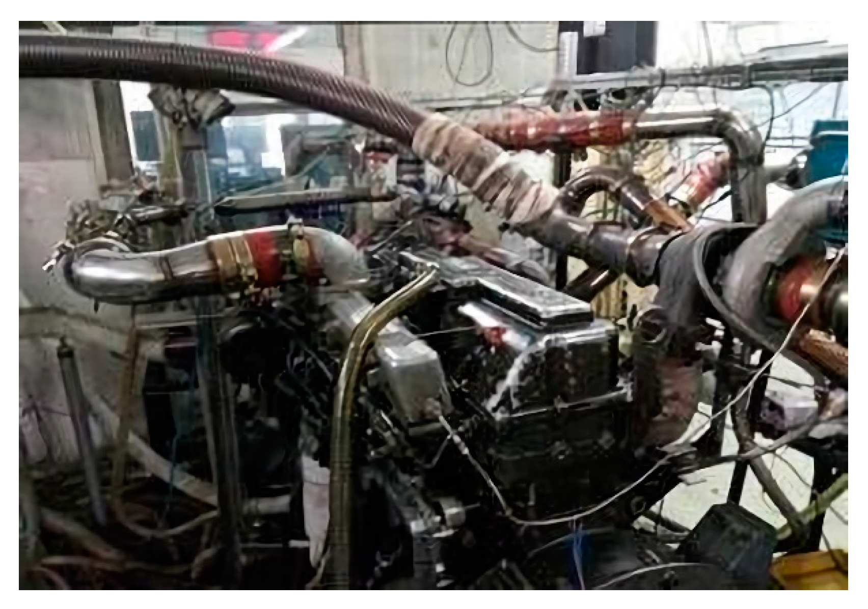
Figure 3 shows the test bench where the experiments data were collected. The experiments were conducted on the modified six-cylinder heavy-duty diesel engine. The sixth cylinder was separated from the other cylinders and was equipped with independent port and directfuel injection systems (DI) to intake temperature and pressure regulating systems, an EGR system, and so on. The engine specifications are shown in Table 1. Major physical properties of diesel used in experiments are shown in 
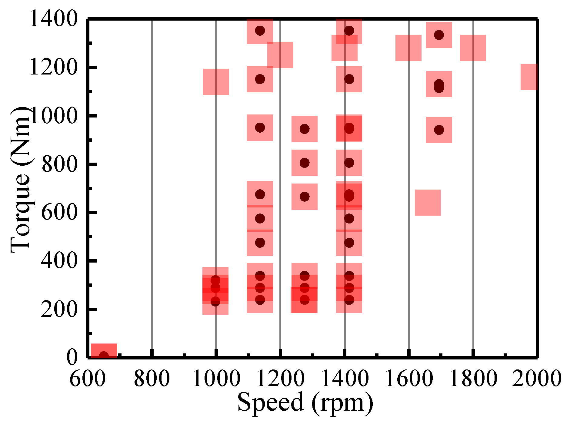
Table 2. Over 3000 experimental data shown in Figure 4 were tested in order to understand the engine performance under various operating conditions. About 2000 cases, marked as black dots, were used for model training, while the other 1000, shown in red squares, were kept for model validation. For each speed/load point in 
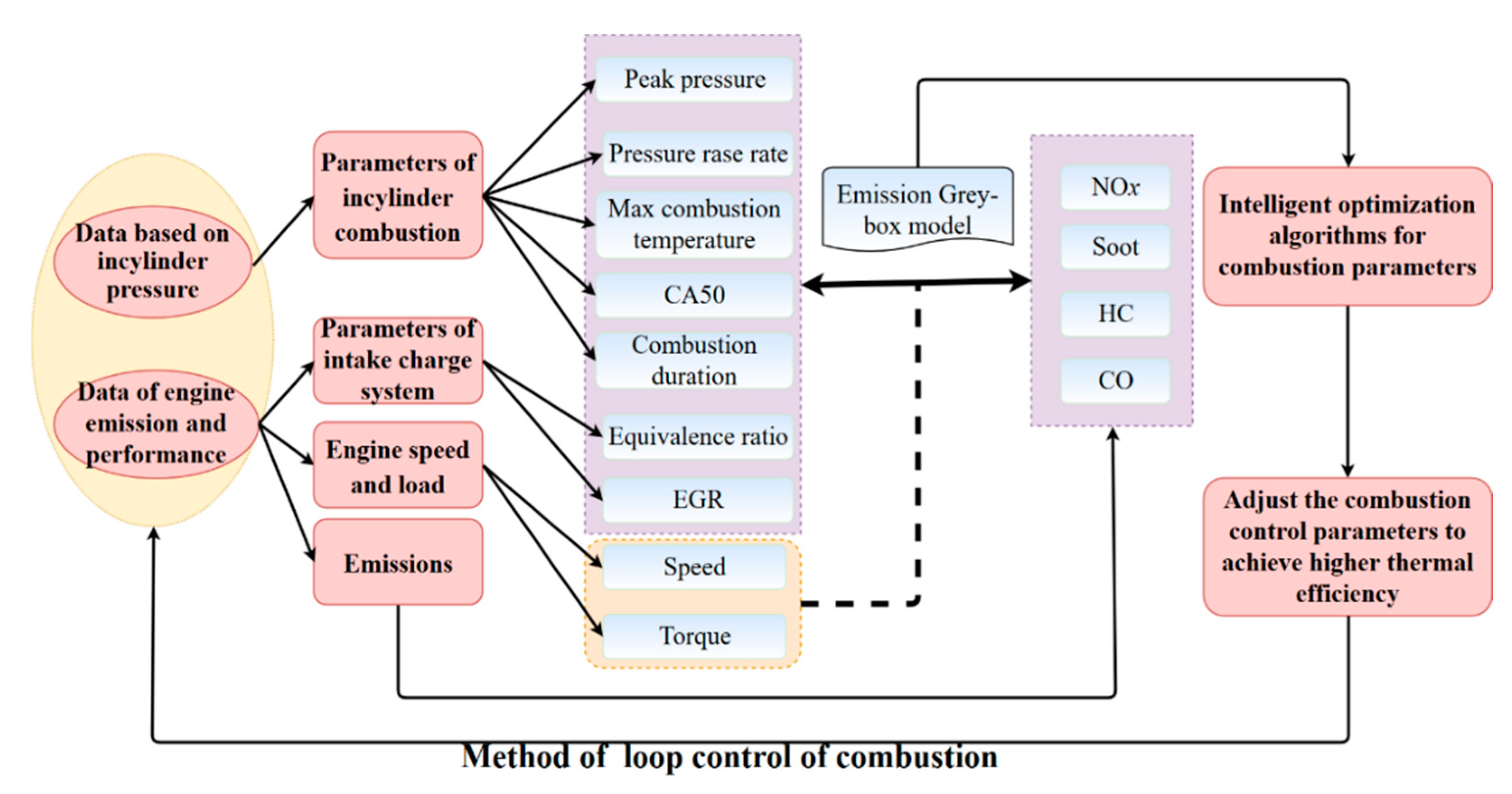
Figure 2, the injection timing, EGR, intake pressure, etc., are different, and a random choice of data was used for the model building/training. Seven parameters representing the combustion characteristics were calculated based on cylinder pressure, as shown in Figure 2. Firstly, sensitivity analysis was performed to study the influence of combustion parameters on emissions and engine thermal efficiency. Table 3 shows the sensitivity of combustion control parameters on engine performance and emissions. For the engine emissions, two combustion control parameters with the highest sensitivity are listed, which also greatly affect the engine performance. For example, EGR and the maximum combustion temperature are mostly sensitive to NOx in this engine under different operating conditions. Therefore, EGR can be an effective method for both combustion and NOx emission control. However, EGR also greatly affects CO, which means that, although massive EGR could restrain NOx, penalty in CO would also be observed. Thus, detailed understanding on the relationship between engine performance and combustion parameters is needed.

3.1. Engine Emission Model Based on Artificial Neural Networks (ANN)

Considering the nonlinear properties of the relationship between combustion parameters and engine performance, ANN is a promising tool to predict engine emissions and thermal efficiency. The typical combustion parameters are obtained based on the in-cylinder pressure. In this paper, a 10-layer ANN, which contains nine neurons in every hidden layer, is implemented and trained with engine test data in MATLAB. Figure 5 shows the prediction results with ANN method, in which the x-coordinate of cycle symbols represents experimental value, while the y-coordinate represents the predicted value. According to the difference between cycle dispersion and perfect fitting line (y = x), it can be seen that the 10-layer ANN is able to predict the NOx and engine thermal efficiency accurately. However, the model prediction is less accurate for soot and CO emissions, owing to their highly non-linear properties. In addition, other factors, such as spray and flow characteristics and combustion chamber geometry, would also affect the engine emission and performance. This increases the uncertainty of ANN prediction results.

3.2. Engine Emission Model Based on Polynomial Functions

Increasing the layers of ANN should be able to improve the prediction accuracy, however, longer calculation time is also needed, which makes it difficult to meet the quick response requirement within the control system. Another way to correlate the combustion parameters with engine performance is to build functions using a known type, such as the equation shown in Equation (1).
Y = f ( n , T o r q u e , , E G R , T m a x , ( d p d φ ) m a x , p m a x , C A 50 , C o m b s _ D u r a t i o n )
in which Y represents the engine outputs, such as HC, NOx emissions, etc. The input variables are the basic operating conditions and combustion parameters described in Figure 2. Therefore, the output can be calculated by the nine variables with a specific formula, 
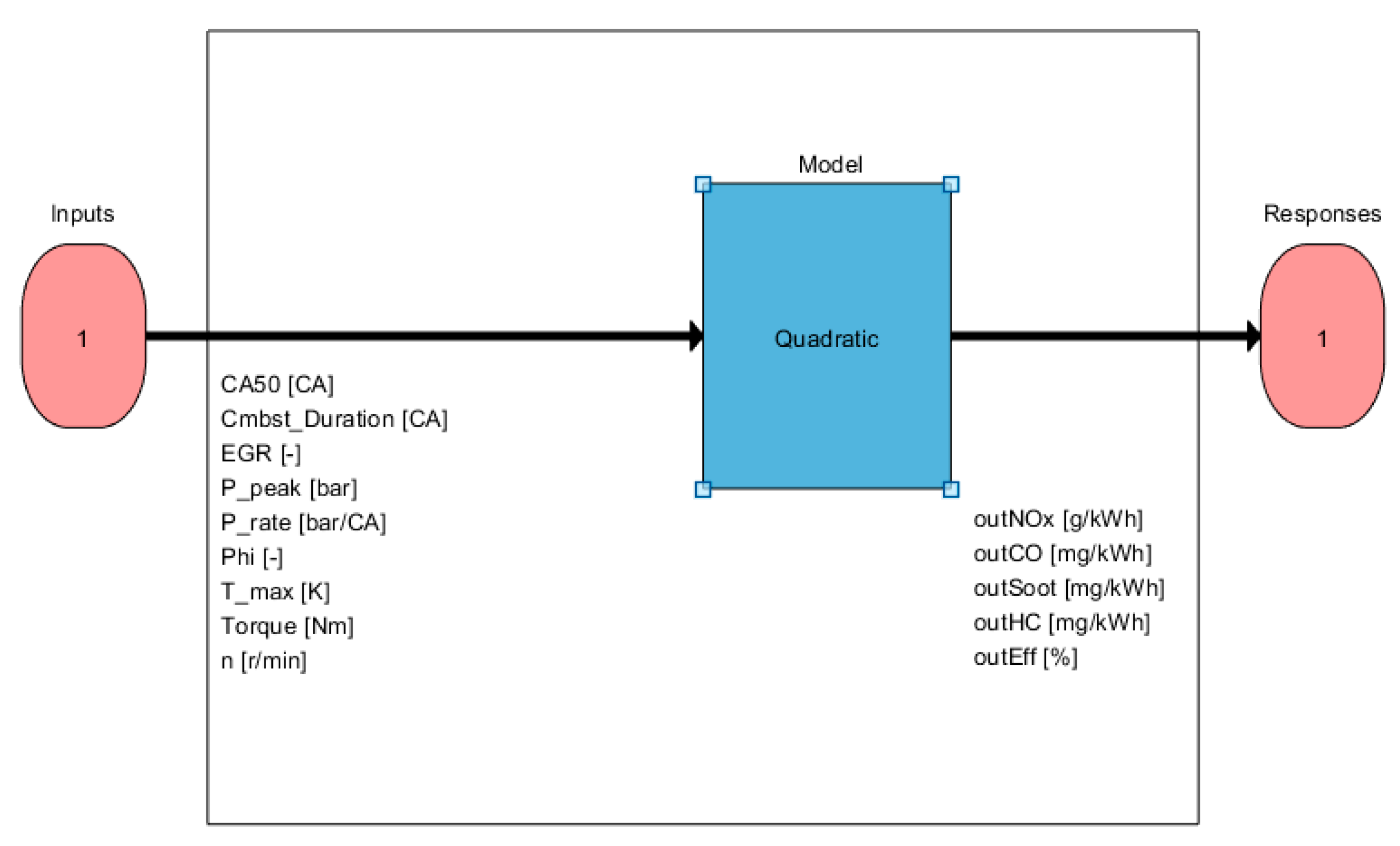
f. In this part, quadratic polynomials are applied, as presented in Equation (2).
y = a 0 + i = 1 n a i x i + i , j = 1 i j n a ij x i x j
With nine inputs, there would be 55 terms at most in Equation (2), considering the coupling effect of every two combustion parameters. A total of 2000 stable engine running cases were used to determine the fitting coefficients in Equation (2). This was conducted with MATLAB Mode-Based Calibration tools, and the model setup is shown in 
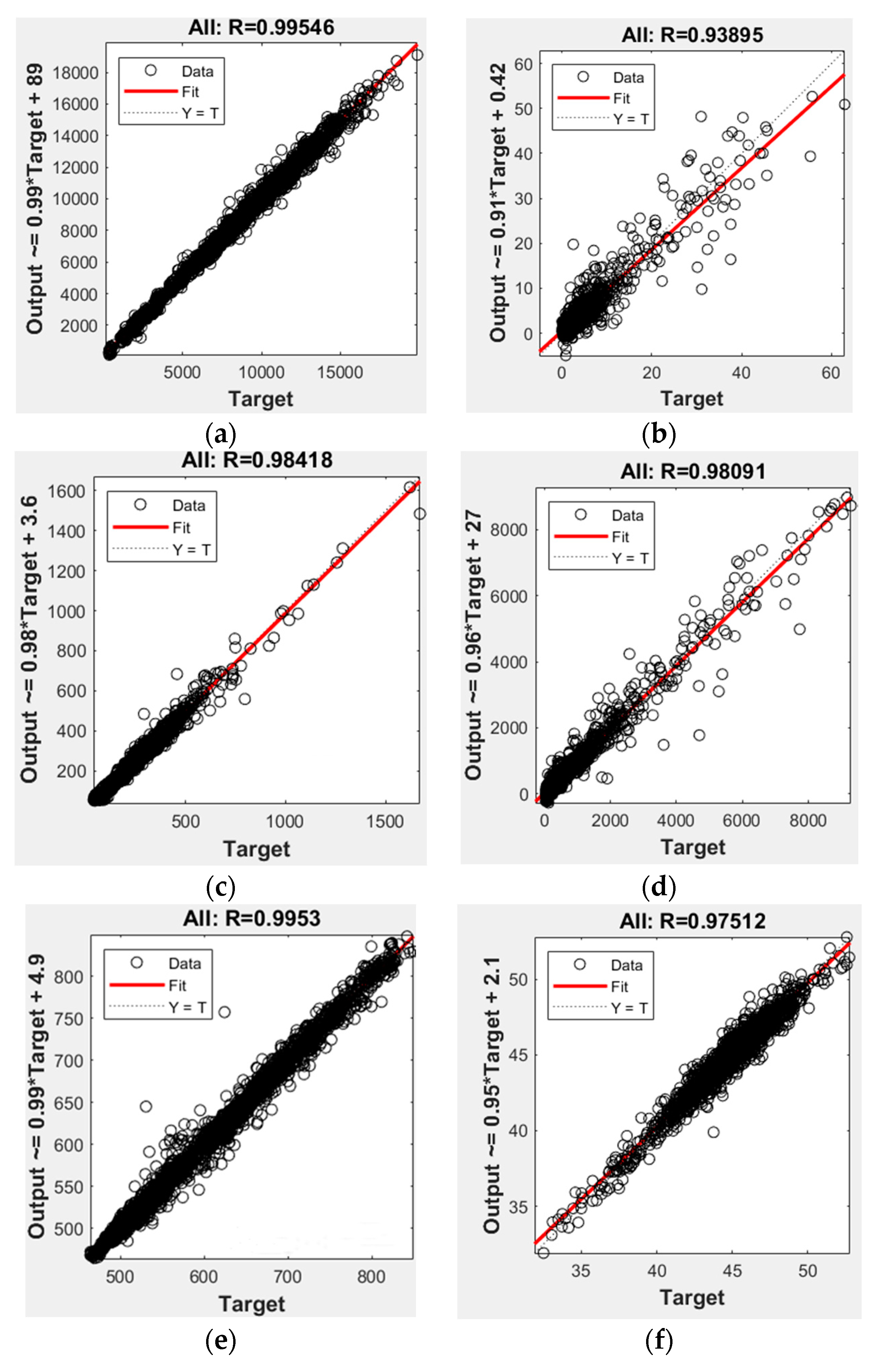
Figure 6. Trained by these stable engine operating data, detailed formulation of Equation (2), which could calculate emissions and engine performances, can be obtained. Equation (3) shows the equation for thermal efficiency calculation, and the prediction results are illustrated in Figure 7. It is found that the quadratic function could also provide reasonable prediction results under most operating conditions. Different from the ANN method, the effect of each combustion parameter can be analyzed with these quadratic functions directly by its partial derivatives. This means that this method is able to help making macroscopic optimization by showing the slope change of engine performance.
Thermal_efficiency = (−77.63 + 2.068*CA50 + 1.38*Combst_Duration − 115.34*Phi + 0.099*T_max + 0.019*n − 0.0166*CA50^2 − 0.0233*CA50*Combst_Duration + 3.016*CA50*EGR + 0.012*CA50*P_peak − 0.063*CA50*P_rate − 0.000642*CA50*T_max − 0.00076*CA50*Torque − 0.000308*CA50*n − 0.0195*Combst_Duration^2 + 0.569*Combst_Duration*Phi − 0.000451*Combst_Duration*T_max + 0.000465*Combst_Duration*Torque + 0.000267* Combst_Duration*n − 21.427*EGR^2 + 1.489*EGR*P_peak + 104.67*EGR*Phi − 0.0269*EGR*T_max − 0.149*EGR*Torque − 0.0406*EGR*n − 1.055*P_peak*Phi + 0.000252*P_peak*T_max + 8.42e-05*P_peak*Torque − 0.000156* P_peak*n +1.869*P_rate*Phi − 0.00103*P_rate* T_max + 0.0013*P_rate*Torque + 0.000832*P_rate*n − 0.0101*Phi* T_max + 0.105*Phi*Torque + 0.0518*Phi*n − 3.378e-5*T_max*Torque − 2.38e-05*T_max*n − 8.66e-06* Torque^2 + 1.016e-5*Torque*n)/100;
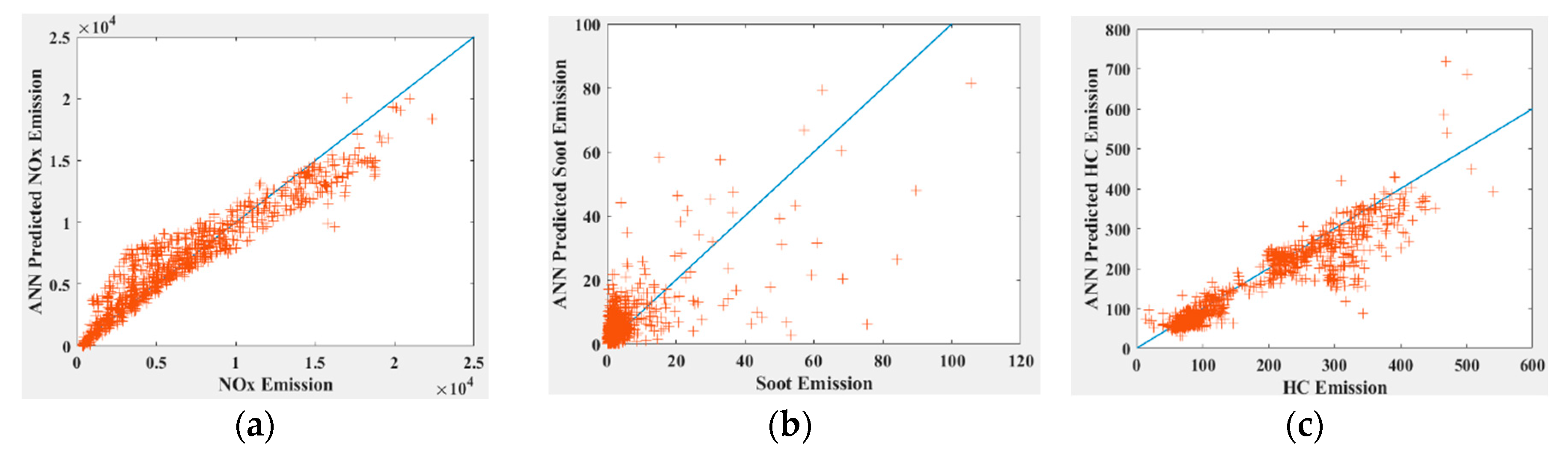
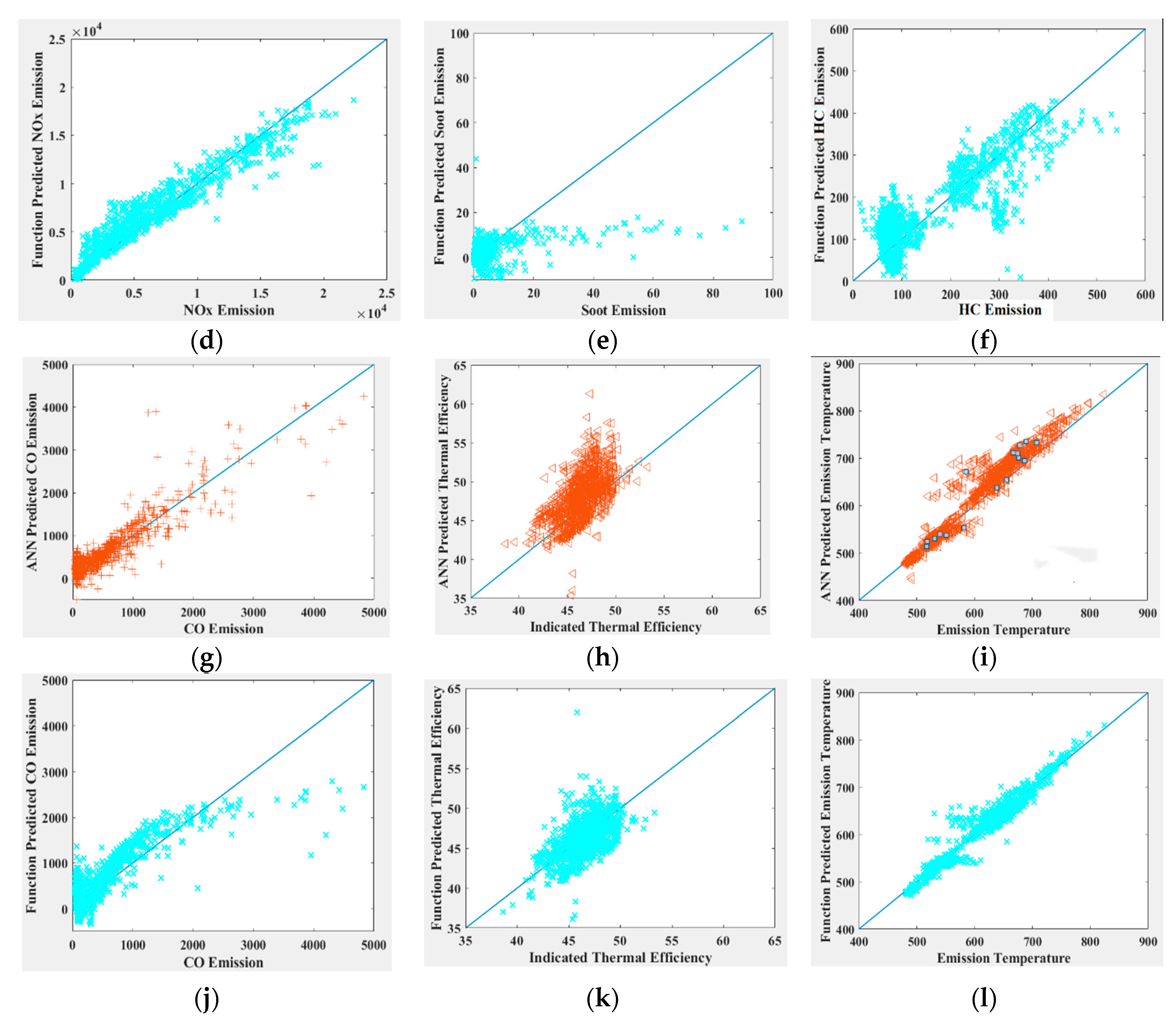
In order to compare the predictive capability of these two methods, another group of data, covering different and wider range of operating conditions, were used for the test and validation (Figure 4; red squares). As shown in Figure 8, the red marks represent the results of the ANN method, while the cyan marks are the results predicted by the quadratic function. In general, both methods show reasonable prediction results for emissions and performance at most conditions. However, combustion products and emissions with highly non-linear characteristics are still difficult to estimate, for example, soot. Besides this, ANN tends to show larger random errors for high value results, while quadratic function tends to underestimate the high value. Comparing the prediction results of NOx and other incomplete combustion products by quadratic function and ANN, the prediction accuracy of quadratic function is similar to that of ANN.

4. Intelligent Optimization Algorithms for Combustion Control Parameters

The relationship between engine performance and combustion parameters can be found to guide the development of optimal combustion control strategy. In this part, the genetic algorithm and fish swarm algorithm are used to find the optimal combustion parameters. The estimated thermal efficiency by the prediction model, which is called virtual thermal efficiency in the following parts, is regarded as the optimization objective. Considering the conversion efficiency of aftertreatment by estimating the exhaust temperature, the final emissions can also be predicted. The engine virtual thermal efficiency will be set as 10%, as long as the emission exceeds the regulation limits. The computing process of the final virtual thermal efficiency is plotted in Figure 9. During the optimization process, quadratic function is applied to calculate the engine emission and performance. The variation ranges of combustion control parameters are shown in Table 4 by analyzing the available engine experimental, and CA50 is calculated by the prediction model, based on the given range of combustion parameters.
Firstly, by applying genetic algorithm, the optimal combustion parameters were searched at 1400 r/min and 945 Nm condition, as shown in Figure 10. The maximum virtual thermal efficiency was obtained after about 50 iterations, and the final optimal combustion parameters are listed in Table 5. Theoretically, the engine thermal efficiency could reach the optimized value, as long as the combustion parameters are controlled to be close to the calculated value. In order to achieve optimal virtual thermal efficiency, the maximum in-cylinder combustion temperature needs to reach 2234 K, and the peak pressure should reach 145.76 bar. However, these two combustion parameters are strongly related to the in-cylinder flow and spray combustion process, and these processes are not only controlled by the overall equivalence ratio and fuel heat value, but also the turbulent intensity and the flame pulsation. This means that these two combustion parameters should be revised and updated, based on the experimental in-cylinder pressure in the real transient loop combustion control, to improve the predicting accuracy of the mathematical model.
Figure 11 shows the optimized results at all these operating conditions, covering engine speed from 1000 r/min to 1600 r/min and torque from 600 Nm to 1300 Nm. It can be seen in Figure 11a that overall lean combustion is beneficial to thermal efficiency improvement, mainly due to the higher specific heat ratio with air dilution. In addition, heat losses could also be reduced with increased heat capacity, owing to more fresh air. Figure 11b,c show the distribution of optimized combustion phase and EGR, respectively. It indicates that an early combustion with relatively higher EGR could be helpful for thermal efficiency improvement at low speed and low load conditions, while EGR rate should be reduced with retarded combustion phase under high speed and high load conditions. By adjusting these combustion control parameters, improvement in virtual thermal efficiency can be obtained, as shown in Figure 11d.
The fish swarm algorithm was also used to study the influence of algorithm on the final optimal prediction results. Figure 12 shows the optimal result with fish swarm algorithm under the same operating conditions (1400 r/min, 945 Nm). For this single case, the fish swarm algorithm took about 1 min to find a higher target value. The optimized combustion parameters are listed in Table 6. It is seen that major differences exist in peak pressure and maximum combustion temperature between these two algorithms, which also affects the pressure rise rate. These combustion parameters also need to be updated with real-time in-cylinder pressure measurement. Considering the optimization process, the genetical algorithm would give more stable results, owing to its fast searching capability for local optimum.
Figure 13 shows the calculated optimal results with fish swarm algorithm. Again, it is observed that overall lean combustion is beneficial for thermal efficiency improvement, as shown in Figure 13a. However, one noticeable difference is that the result with fish swarm algorithm indicating higher EGR should be adopted only at low load conditions (Figure 13c). With the increase of engine speed and load, the combustion phase advances at some cases while retards at other cases (Figure 13b). This can be explained by the random effect of combustion control parameters and the characteristics of fish swarm algorithm. On the one hand, as a complex multiobjective optimization problem, the ideally global optimal combustion parameters might not exist. A small error in peak pressure could lead to completely different optimization direction. On the other hand, excessively searching for the global optimal combustion parameters would result in unrealistic value.
Comparing the results in Figure 11d and Figure 13d, it is seen that the genetic algorithm performs better than the fish swarm algorithm in searching for optimal combustion control parameters. With reasonable amendment, an emission prediction model coupled with a genetic algorithm can be an option for combustion loop control.

5. Conclusions

The innovation of this paper is the introduction of the ANN and AI method to establish the prediction model of engine emissions and performance through combustion characteristic parameters, and the performance and emission of engine are optimized under different operating conditions. Finally, combined with some transient experimental data, the control scheme of the model in the actual engine is explored, and the corresponding control strategy is proposed, which has high value in practice. Several major conclusions can be drawn, as follows:
(1)
In order to construct a feasible model for combustion control, seven major combustion parameters are extracted, to represent the combustion characteristics of a diesel engine, based on measured in-cylinder pressure. It is seen that both the ANN and quadratic functions can reasonably well reproduce the engine performance and emissions over wide operating conditions. However, more effort should be expended on the prediction of non-linear emissions, such as soot.
(2)
CA50 is the main combustion parameter which defines the combustion heat release center. Compared to the traditional ANN method, optimal CA50 can be firstly determined with quadratic functions, and the other combustion parameters can be optimized with AI, which proved to be a more realistic way for model-based combustion control. Based on this rule, a multiobjective function is proposed to optimize engine emissions and thermal efficiency.
(3)
Two intelligent optimization algorithms are applied to search the optimal combustion parameters. The genetical algorithm shows more stable results and faster convergence than the fish swarm algorithm. With AI, the optimal combustion parameters can be identified and estimated much faster, and the results can be further used for the adjusting of combustion strategy.
Further research exists in achieving the optimal combustion process by adjusting combustion boundary conditions. In addition, more transient data will be used to assess the capability and stability of this combined loop control method.

Author Contributions

Conceptualization, H.W. and T.M.; methodology, T.M.; software, T.M.; validation, X.Z. and T.M.; formal analysis, Z.Z.; investigation, H.W., X.Z. and T.M.; resources, Z.Z.; writing—original draft preparation, T.M.; writing—review and editing, X.Z.; supervision, M.Y. All authors have read and agreed to the published version of the manuscript.

Funding

This work was supported by the foundation of National Key R&D Program of China (2017YFB0103501) and the National Natural Science Fund of China (NSFC) through the Projects of 51876140.

Conflicts of Interest

The authors declare that there are no conflict of interest.

Nomenclature

ANNArtificial neural networkP_ratePressure rise rate
CA50Combustion phasing defined by the Crank Angle of 50% accumulative heat releasePhiEquivalence ratio
EGRExhaust gas recirculationT_maxMax combustion temperature
Combs-DurationCombustion durationoutEffIndicated thermal efficiency
pmax/P_peakPeak pressurePMParticulate matter
DIDirect injection

References

  1. Saracino, R.; Gaballo, M.R.; Mannal, S.; Motz, S.; Carlucci, A.; Benegiamo, M. Cylinder Pressure-Based Closed Loop Combustion Control: A Valid Support to Fulfill Current and Future Requirements of Diesel Powertrain Systems; SAE Technical Paper: Warrendale, PA, USA, 2015. [Google Scholar]
  2. Spessa, E.; D’Ambrosio, S.; Iemmolo, D.; Mancarella, A.; Vitolo, R.; Hardy, G. Steady-State and Transient Operations of a Euro VI 3.0 L HD Diesel Engine with Innovative Model-Based and Pressure-Based Combustion Control Techniques. SAE Int. J. Eng. 2017, 10, 1080–1092. [Google Scholar] [CrossRef]
  3. Schnorbus, T.; Pischinger, S.; Körfer, T.; Lamping, M.; Tomazic, D.; Tatur, M. Diesel Combustion Control with Closed-Loop Control of the Injection Strategy; SAE Technical Paper: Warrendale, PA, USA, 2008. [Google Scholar]
  4. Haskara, I.; Wang, Y.Y. Cylinder pressure-based combustion controls for advanced diesel combustion with multiple-pulse fuel injection. IEEE Trans. Control Syst. Technol. 2012, 21, 2143–2155. [Google Scholar] [CrossRef]
  5. Fang, C.; Ouyang, M.; Tunestal, P.; Yang, F.; Yang, X. Closed-loop combustion phase control for multiple combustion modes by multiple injections in a compression ignition engine fueled by gasoline-diesel mixture. Appl. Energy 2018, 231, 816–825. [Google Scholar] [CrossRef]
  6. Ott, T.; Zurbriggen, F.; Onder, C.; Guzzella, L. Cylinder individual feedback control of combustion in a dual fuel engine. IFAC Proc. Vol. 2013, 46, 600–605. [Google Scholar] [CrossRef]
  7. Hu, Y.; Zhou, T.; Yao, C.; Yang, F.; Wang, J.; Ouyang, M.; Huang, H. Accommodation Closed-loop Control of Dieseline Fueled Flexible Fuel Engine Based on In-cylinder Pressure Sensor. IFAC-PapersOnLine 2016, 49, 202–209. [Google Scholar] [CrossRef]
  8. Yao, C.; Hu, Y.; Zhou, T.; Yang, F.; Ouyang, M.; Huang, H. Combustion Stability Control of Dieseline PPCI Based on In-Cylinder Pressure Signals. IFAC-PapersOnLine 2016, 49, 333–339. [Google Scholar] [CrossRef]
  9. Willems, F.; Doosje, E.; Engels, F.; Seykens, X. Cylinder Pressure-Based Control in Heavy-Duty Egr Diesel Engines Using a Virtual Heat Release and Emission Sensor; SAE Technical Paper: Warrendale, PA, USA, 2010. [Google Scholar]
  10. Thor, M.; Egardt, B.; McKelvey, T.; Andersson, I. Closed-loop diesel engine combustion phasing control based on crankshaft torque measurements. Control Eng. Pract. 2014, 33, 115–124. [Google Scholar] [CrossRef]
  11. Jun, W.; Yi, T.; Yi-lin, W. Extract of Combustion Characteristic Information and Its Feedback Establishing in Diesel Engine. In Proceedings of the 2017 4th International Conference on Information Science and Control Engineering (ICISCE), Changsha, China, 21–23 July 2017; IEEE: Piscataway, NJ, USA, 2017; pp. 321–325. [Google Scholar]
  12. Oğuz, H.; Sarıtas, I.; Baydan, H.E. Prediction of diesel engine performance using biofuels with artificial neural network. Expert Syst. Appl. 2010, 37, 6579–6586. [Google Scholar] [CrossRef]
  13. d’Ambrosio, S.; Finesso, R.; Fu, L.; Mittica, A.; Spessa, E. A control-oriented real-time semi-empirical model for the prediction of NOx emissions in diesel engines. Appl. Energy 2014, 130, 265–279. [Google Scholar] [CrossRef]
  14. Verma, R.; Lakshminiarayanan, P.A. A case study on the application of a genetic algorithm for optimization of engine parameters. Proc. Inst. Mech. Eng. Part D J. Automob. Eng. 2006, 220, 471–479. [Google Scholar] [CrossRef]
  15. Alonso, J.M.; Alvarruiz, F.; Desantes, J.M.; Hernández, L.; Hernández, V.; Molto, G. Combining neural networks and genetic algorithms to predict and reduce diesel engine emissions. IEEE Trans. Evol. Comput. 2007, 11, 46–55. [Google Scholar] [CrossRef]
  16. Liu, H.; Ma, X.; Li, B.; Chen, L.; Wang, Z.; Wang, J. Combustion and emission characteristics of a direct injection diesel engine fueled with biodiesel and PODE/biodiesel fuel blends. Fuel 2017, 209, 62–68. [Google Scholar] [CrossRef]
Figure 1. Structure of this paper.
Energies 13 06046 g001
Figure 2. Diagram of combustion loop control algorithm.
Energies 13 06046 g002
Figure 3. Test bench.
Energies 13 06046 g003
Figure 4. Driving cycles of all testing data.
Energies 13 06046 g004
Figure 5. (a) NOx (b) Soot (c) HC (d) CO (e) Exhaust gas temperature (f) Thermal efficiency. Results of prediction based on artificial neural network (ANN).
Energies 13 06046 g005
Figure 6. Model setup in Mode-Based Calibration tools.
Energies 13 06046 g006
Figure 7. Results of prediction of virtual thermal efficiency based on quadratic function.
Energies 13 06046 g007
Figure 8. (a) NOx (b) Soot (c) HC (d) NOx (e) Soot (f) HC (g) CO (h) Thermal efficiency (i) Exhaust gas temperature (j) CO (k) Thermal efficiency (l) Exhaust gas temperature. Comparison of prediction ability between ANN and polynomial function.
Energies 13 06046 g008aEnergies 13 06046 g008b
Figure 9. Framework of virtual thermal efficiency calculation.
Energies 13 06046 g009
Figure 10. Optimizing process of genetic algorithm.
Energies 13 06046 g010
Figure 11. (a) Phi (b) CA50 (c) EGR (d) Virtual thermal efficiency. Optimizing results based on the genetic algorithm.
Energies 13 06046 g011
Figure 12. Optimizing process of fish swarm algorithm.
Energies 13 06046 g012
Figure 13. (a) Phi (b) CA50 (c) EGR (d) Virtual thermal efficiency. Optimal results based on fish swarm algorithm.
Energies 13 06046 g013
Table 1. Engine specifications.
Engine displacement8.42 L
Bore/stroke113 mm × 140 mm
Compression ratio16.8
Fuel injector8 holes, injection cone angle 148°, nozzle diameter 0.163 mm
Rated power/speed243 kW/2200 rpm
Rated torque/speed1350 Nm/(1100–1700 rpm)
Table 2. Major physical properties of diesel.
Molecule FormulaBoiling Point (°C)Density (g/cm3@25 °C)Cetane NumberLow Heating Value (MJ/kg)Kinetic Viscosity (MPa s)
C12–C15190–3400.8345142.63.24
Table 3. Sensitivity of combustion control parameters.
Most Sensitive Combustion Variable
Thermal efficiencyCombustion duration, CA50
SootEquivalence ratio, Combustion duration
NOxEGR, Max combustion temperature
HCMax combustion temperature, Peak pressure
COCombustion duration, EGR
Exhaust gas temperatureMax combustion temperature, Equivalence ratio
Table 4. The variation range of combustion control parameters.
Range of Variation
Equivalence ratio[0.28, 1.03]
EGR[0.004, 0.5]
Max combustion temperature (K)[1350, 2700]
Peak pressure (MPa)[5, 17.3]
Pressure rise rate (MPa/CA)[0.19, 1.18]
Combustion duration (CA)[6.5, 39.5]
Table 5. Optimized combustion control parameters.
Equivalence RatioEGRMaximum Combustion Temperature (K)Peak Pressure (bar)Pressure Rise Rate (bar/°CA)Combustion Duration (°CA)CA50 (°CA ATDC)
0.650.36552234.2145.768.0528.538.75
Table 6. Optimized combustion parameter.
Equivalence RatioEGRMaximum Combustion Temperature (K)Peak Pressure (bar)Pressure Rise Rate (bar/°CA)Combustion Duration (°CA)CA50 (°CA ATDC)
0.490.3632068.2167.8611.5322.048.84
Publisher’s Note: MDPI stays neutral with regard to jurisdictional claims in published maps and institutional affiliations.

